highly efficient igfc hybrid power systems employing ...aes.mines.edu/publications/journals/braun et...
TRANSCRIPT

R. J. BraunEngineering Division,
Colorado School of Mines,
Golden, CO 80401
S. Kameswaran
J. Yamanis
E. Sun
United Technologies Research Center,
East Hartford, CT 06108
Highly Efficient IGFC HybridPower Systems EmployingBottoming Organic RankineCycles With Optional CarbonCaptureThis study examines the performance of a solid oxide fuel cell- (SOFC-) based integratedgasification power plant concept at the utility scale (>100 MW). The primary system con-cept evaluated was a pressurized �150 MW SOFC hybrid power system integrated withan entrained-flow, dry-fed, oxygen-blown, slagging coal gasifier and a combined cycle inthe form of a gas turbine and an organic Rankine cycle (ORC) power generator. The ana-lyzed concepts include carbon capture via oxy-combustion followed by water knockoutand gas compression to pipeline-ready CO2 sequestration conditions. The results of thestudy indicate that hybrid SOFC systems could achieve electric efficiencies approaching66% [lower heating value (LHV)] when operating fueled by coal-derived clean syngasand without carbon dioxide capture. The system concept integrates SOFCs with the low-pressure turbine spool of a 50 MW Pratt & Whitney FT8-3 TwinPak gas turbine set anda scaled-up, water-cooled 20 MW version of the Pratt & Whitney (P&W) PureCycleORC product line (approximately 260 kW). It was also found that a system efficiency per-formance of about 48% (LHV) is obtained when the system includes entrained-flow gasif-ier and carbon capture using oxygen combustion. In order to integrate the P&W FT8into the SOFC system, the high-pressure turbine spool is removed which substantiallylowers the FT8 capital cost and increases the expected life of the gas turbine engine. Theimpact of integrating an ORC bottoming cycle was found to be significant and can add asmuch as 8 percentage points of efficiency to the system. For sake of comparison, the per-formance of a higher temperature P&W ORC power system was also investigated. Use ofa steam power cycle, in lieu of an ORC, could increase net plant efficiency by another4%, however, operating costs are potentially much lower with ORCs than steam powercycles. Additionally, the use of cathode gas recycle is strongly relevant to efficiency per-formance when integrating with bottoming cycles. A parameter sensitivity analysis of thesystem revealed that SOFC power density is strongly influenced by design cell voltage,fuel utilization, and amount of anode recycle. To maximize the power output of the modi-fied FT8, SOFC fuel utilization should be lower than 70%. Cathode side design parame-ters, such as pressure drop and temperature rise were observed to only mildly affectefficiency and power density. [DOI: 10.1115/1.4004374]
1 Introduction
Solid oxide fuel cells (SOFCs) are considered to be a key tech-nology for high-efficiency, zero-emission fossil power plants ofthe future. In particular, the accelerating development activity ofSOFCs under the auspices of the U.S. DOE Solid State EnergyConversion Alliance (SECA) program is focused on utilizingSOFCs as building blocks for large-scale integrated coal-gasification power plants. When SOFCs are fueled from coal syn-gas and combined with gas turbines, an ultra-high efficiencyhybrid system can be obtained. A steam Rankine bottoming cycle(SRC) can also be integrated to further enhance efficiency andpower production and carbon dioxide capture and sequestration(CCS) is necessary to achieve near-zero emission levels. It hasbeen estimated that an integrated gasification fuel cell (IGFC)power plant with CCS can achieve an efficiency advantage of
nearly 24 percentage points over a comparable integrated gasifica-tion combined cycle plant with CCS [1].
There are numerous challenges in integrating the many sub-systems that comprise an IGFC power plant. Achieving robustoperability and control and a flexible operating envelope in a cost-effective manner are significant concerns for hybrid power systems,especially those involving numerous unproven technologies. Tech-nical challenges include gasifier-fuel cell integration, fuel cell-gasturbine integration, power block integration with carbon capturehardware, and system control. Gasifier-fuel cell integration is sub-ject to the very narrow operating envelope of SOFC technologyestablished by both tolerance to anode fuel gas impurities, and cell-stack temperature and pressure control. Excursions of reactant gastemperatures, pressures, and compositions from design conditionscan lead to cell cracking, carbon deposition, anode oxidation, andaccelerated cell degradation (reduced lifetime). Fuel cell-gas tur-bine integration is subject to the same SOFC operating constraintsas gasifier integration and is further hampered by several controlchallenges that involve compressor surge, shaft overspeed, and celloverheating [2]. Detailed examination of the integration challenges
Contributed by the International Gas Turbine Institute (IGTI) for publication inthe JOURNAL OF ENGINEERING FOR GAS TURBINES AND POWER. Manuscript received June18, 2010; final manuscript received May 18, 2011; published online December 14,2011. Assoc. Editor: Paolo Chiesa.
Journal of Engineering for Gas Turbines and Power FEBRUARY 2012, Vol. 134 / 021801-1Copyright VC 2012 by ASME
Downloaded 14 Dec 2011 to 138.67.11.94. Redistribution subject to ASME license or copyright; see http://www.asme.org/terms/Terms_Use.cfm

is beyond the scope of this paper, but the interested reader isreferred to several literature studies on the topic [2–9].
Despite the numerous technical challenges that need to be over-come, both the efficiency performance and the economics of“mature” IGFC systems are promising. Recent economic assess-ments of large-scale (>100 MW) integrated gasification combinedcycle (IGCC) plants employing entrained-flow gasifiers and F-class syngas turbines have estimated total plant capital costs atabout $1800/kW1 (in 2007$) using commercially available tech-nologies without carbon capture [1,10]. It is estimated that captur-ing carbon dioxide in these plants adds another 30% to the totalplant capital cost [1]. In contrast, the cost of an IGFC plant thatemploys catalytic gasifier technology and carbon capture has beenestimated to reduce the plant capital cost by 30% (i.e., �$1670/kW) while offering an efficiency advantage of nearly 24 percent-age points over its IGCC/CCS counterpart [1]. Such cost and per-formance advantages make IGFC/CCS systems very attractive;however, considering the substantial technical challenges of real-izing these performance expectations, continued exploration ofsystem integration concepts is warranted.
The objectives of the present work are to (1) quantify IGFC sys-tem performance using commercial coal gasifier, gas turbine, andorganic Rankine cycle (ORC) technologies, (2) perform a sensitiv-ity study of system performance due to variations in SOFC powerblock design parameters, and (3) identify additional areas for sys-tem design and performance improvements.
There are several prior theoretical research efforts in the openliterature that have examined integrating SOFCs with coal gasifi-cation and power generation cycles. In particular, Lobachyovand Richter evaluated integrating an indirectly heated fluidized-bed coal gasifier with gas turbine and SOFC [11]. Efficienciesexceeding 60%-LHV were reported with generic gas turbine andobsolete monolithic SOFC technologies and no carbon capture.Kivisaari et al., [12] examined integration of an entrained-flowgasifier with either molten carbonate or solid oxide fuel celltechnology for combined heat and power (CHP). In this study,integration with power cycles was not performed nor was CO2
capture of interest. Similarly, Ghosh and De carried out a studyon employing entrained-flow gasification with SOFCs; however,gas and steam turbine integration for CHP were also incorpo-rated [13]. Verma et al., [14] performed an analysis on IGFCsystems inclusive of a steam cycle, ion transport membrane, andcarbon capture technologies. SOFC parameter and system con-ceptual design variations were studied and efficiencies as high as50%-HHV were reported. More recently, Romano et al., exam-ined an IGFC system operating with an oxygen-blown,entrained-flow Shell gasifier [15]. The study details the integra-tion of gasifier and power block islands, but does not offer car-bon capture and sequestration. A sensitivity analysis of SOFCpressure and fuel and oxidant utilizations is given. Results of a7–11 percentage point efficiency gain over advanced IGCC sys-tems are reported. Liese reported on an IGFC system perform-ance with pre- and post-SOFC carbon capture for a hybridsystem employing a Conoco-Philips gasifier and a bottomingsteam Rankine cycle [16]. The focus of this study was on theimpact of various carbon capture methods. IGFC studies thatemploy low-temperature catalytic gasification have also beenmade [17,18]. These studies show even more promising effi-ciency performance potential of IGFC hybrid systems in part dueto the methane content of gasifier syngas and the associated ben-efit to the SOFC power block. In terms of SOFC-ORC hybridsystems, Verda performed an integration study with a natural gasfueled commercial-scale tubular SOFC system of about 100 kWand a 30 kW ORC system [19]. Results point to a 5.6% effi-ciency improvement from the addition of the bottoming ORCsystem.
2 Methodology
The focus of the present work is on the performance assessmentassociated with the system integration of gas turbine and Rankinecycle hardware with that of the SOFC power block and presumeschallenges associated with gasifier-SOFC/GT integration andoverall system control have been overcome. In this paper, weexamine the expected performance of an IGFC power plant whenthe SOFC power section is integrated with modified and/orscaled-up commercial gas turbine and ORC power generationtechnology. A schematic overview of the main process steps of acoal-based IGFC hybrid system with ORC and post-combustionCO2 capture is given in Fig. 1. The first step of the IGFC systemis production of a syngas through gasification of the coal feed-stock. The coal is fed into the high-pressure gasifier using nitrogenas an inert pressurizing agent that is supplied from the air separa-tion unit. Syngas cleanup and cooling occur next before admit-tance into the SOFC power block. In one sense, the IGFC systemis very similar to its more conventional integrated gasificationcombined cycle (IGCC) counterpart in that the SOFC serves as acombustor that also produces electric power. Thus, the compres-sor of the gas turbine supplies air to the SOFC unit and the heatgain of the cathode air from the SOFC processes is returned to theturbine. The depleted anode tail-gas is kept separate from thecathode gases and is sent to the oxycombustor where the remain-ing fuel gas is combusted. Thermal energy is recovered from bothgas turbine and oxycombustor exhaust gases via the ORC bottom-ing cycle. Carbon dioxide is separated in the final stage of theplant process as shown in Fig. 1. While an ORC bottoming cycleoffers lower efficiency than a conventional steam cycle given theavailability of the relatively high temperature heat sources in theIGFC system, there are potential cost benefits associated withintegration of an ORC system that merit further exploration of itspotential use. Further discussion is given in the subsequent sectionof this paper.
Integrated coal-gasification fuel cell power plant concepts havebeen investigated using modeling and simulation. The plant con-cepts evaluated feature entrained-flow gasifiers integrated withplanar SOFC technology, Pratt & Whitney gas turbines, carboncapture via oxy-combustion of the anode tail-gas, and waste heatrecovery through organic Rankine cycle systems. Physics-basedcomponent models and diagnostic tools previously developed atUTC facilitate fast prototyping of innovative fuel cell, turbine,and combined heat and power system configurations. The currentsystem-level models have been generated employing zero-dimensional thermodynamic component models.
A viable system configuration was first established and sizingof the SOFC power block was derived from matching of reactantflows to the P&W FT8 gas turbine requirements. Design parame-ters were then varied to gauge performance sensitivity. Key pa-rameters and the ranges explored are summarized in Table 1.Bounds for the range were constrained by hardware performancecharacteristics, such as maximum SOFC outlet temperature, orflow and compressor pressure ratios for the gas turbine spool.
3 Technologies
System technologies employed in the integrated gasificationfuel cell power plant concept designs are briefly described below.
3.1 Coal Gasifier. The gasifier employed in the IGFC systemanalysis is a dry-fed oxygen-blown, entrained-flow slagging gasif-ier representative of Shell gasifier technology. It was assumed thatthe cold-gas gasifier efficiency (defined as LHV syngas out overLHV coal feed in) was 82% [20]. In this study, the focus was oneffective integration of the prime movers, and thus gasifier andsyngas cleanup sub-systems were not integrated with the SOFC-combined cycle power block. All steam generation needs for thegasifier and gas cleanup unit operations are generated by syngasprocess cooling needs, which can exceed the thermal energy
1This cost reflects an overnight installed capital cost that can be 50% lower thanactual turn-key plant cost.
021801-2 / Vol. 134, FEBRUARY 2012 Transactions of the ASME
Downloaded 14 Dec 2011 to 138.67.11.94. Redistribution subject to ASME license or copyright; see http://www.asme.org/terms/Terms_Use.cfm

required for steam generation by as much as 250%. Thus, whilesuch integration considerations are not a focus of the currentstudy, auxiliary power requirements in the gasifier and cleanupoperations could easily be met with expanders or larger ORCcapacity. The excess process heat that is available could beemployed to drive an ORC or SRC system and produce additionalpower thereby, increasing system efficiency. The potential reduc-tion in system efficiency is estimated2 at 1–2 percentage pointsfrom lack of tight thermal integration with power block and syn-gas production and cleanup unit operations, making the perform-ance predictions given in the forthcoming sections moreconservative.
3.2 SOFC Technology. The solid oxide fuel cell stack isbased on planar cell technology that achieves performance levelsconsistent with DOE SECA performance targets, such as powerdensity and cathode temperature rise. The “high performance”cell technology is based on a porous nickel yttria-stabilizedzirconia (YSZ) anode support, a dense YSZ electrolyte membrane(�10 lm) and a porous strontium-doped lanthanum cobalt ferrite(LSCF) cathode electrode. The cell and the balance-of-stack com-ponents are optimized for 40 000 h durability. The stack powersection is assumed to operate at low (3 kPa) pressure drops onboth the anode and cathode gas streams in order to minimize para-
sitic power loss. The stack design and the stack arrangement forMW-scale power plants can be tailored to operate under near am-bient (�1.0 bar) or elevated pressures (�5 bar). The anode-supported SOFC technology employed in this study typicallyoperates in the 750–775 �C range with a maximum cathodeoutlet temperature of 850 �C, and with a cell power density of0.45 W/cm2 on syngas.
3.3 Gas Turbine. The gas turbine technology utilized in thisstudy is based on the Pratt & Whitney FT8 Twin PAC 50 MWpower system. It is comprised of two-single 25 MW, 37%-LHVefficiency (on natural gas) systems coupled to a single generator.The FT8 POWERPAC single-engine 25 MW gas turbine fromPratt & Whitney Power Systems is a 3600-rpm machine employedfor 60 Hz electric power generation and has demonstrated opera-tion in combined cycle (GT/steam Rankine cycle).
Figure 2 shows a simplified schematic of an aeroderivative gasturbine power generator. The engine is mainly comprised of alow-pressure compressor, high-pressure spool (compressor, tur-bine, and shaft), low-pressure turbine, power turbine, and synchro-nous 60 Hz generator. The low-pressure compressor typicallydevelops a pressure ratio of 4.5, but can go as high as 5.2 bar. Thehigh-pressure spool employs a concentric shaft and includes high-pressure compressor, diffuser, combustor, and high-pressure tur-bine components. The high-pressure spool operates at a speedgreater than the low-pressure spool and the operating pressure ofthe combustor is typically on the order of 18–19 bar. As the SOFCdesign operating pressure is 5 bar, removal of the high-pressure
Table 1 Parameters for system-level sensitivity study
Parameter Range
System operating pressure 3–5 barNominal SOFC operating temperature 775 �C (fixed)Allowable cathode air temperature rise 75–150 �CSOFC cathode pressure drop 2–10 kPaSOFC fuel utilization 66–86%SOFC average single cell voltage 0.68–0.79 V/cell
Fig. 2 Simplified schematic diagram of PW FT8-series gas tur-bine power generator
Fig. 1 Schematic overview of coal-based IGFC hybrid system with ORC and post-combustionCO2 capture
2The estimation is made by taking the 250% excess process thermal energy andgenerating power through either ORC or SRC power cycles at the efficienciesemployed in this analysis.
Journal of Engineering for Gas Turbines and Power FEBRUARY 2012, Vol. 134 / 021801-3
Downloaded 14 Dec 2011 to 138.67.11.94. Redistribution subject to ASME license or copyright; see http://www.asme.org/terms/Terms_Use.cfm

spool of turbine when integrating with the SOFC is required. Oneof the challenges in matching a gas turbine power generator withan IG-SOFC topping plant is in the potential flow mismatchbetween compressor and expander due to the use of the low-calorific coal syngas in the system. When the SOFC capacity isselected to match the design flow rate and pressure ratio (PR) ofthe low-pressure compressor (LPC) section of the FT8 gas turbineproduct line, the mass flow delivered to the low-pressure turbine(LPT) section is too large for the unit. Another challenge is thatsince the high-pressure spool has been removed, the required inletpressure to the low-pressure turbine is 2 bar higher than the outletpressure available from the low-pressure compressor. Thus, re-moval of the high pressure spool presents an off-design aerody-namic inlet condition, even in cases where the compressor andturbine flowrates are properly matched. If the mismatch in eitherflow and pressure ratio are large enough, significant speed differ-ences between turbine and compressor may exist which then ne-cessitate the addition of a gearbox or other workaround solution.Matching the SOFC exhaust gas flow to the maximum LPT flowcapacity was considered to be the best approach as it avoided theneed to vent compressor air flow to the surroundings, while theoff-design flow delivered to the LP compressor still enabled ahigh-efficiency operating point to be achieved.
A high-level engineering design change analysis was carriedout by P&W to assess both the number and magnitude of changesrequired to modify an FT8-3 generator for integration with a pres-surized IG-SOFC power plant. Removal of the high-pressurespool necessitates consideration of lubrication systems, secondaryair systems management (bleed streams), exhaust and inlet volutedesigns, engine rotor dynamics, and engine gearbox/startup modi-fications. Overall, changes to the existing FT8-3 engine design areconsidered to be significantly simpler and more cost-effectivethan either making design changes to a different product line or inbeginning a new turbine development program. Additionally, FT8design changes are estimated to result in a 40% reduction in capi-tal cost on the engine itself and a 10–15% overall capital costreduction of the gas generator when considering the supportinghardware, sub-system, and parts count reduction. Other synergies,such as a reduction in turbine maintenance and an increase inengine life, are also anticipated due to the design changes outlinedabove.
3.4 Organic Rankine Cycle. The ORC technology to beintegrated at the utility-scale is based on modular designs that donot have a strong pressure-flow coupling with the topping systems(i.e., syngas production, SOFC, and GT) due to thermal integra-tion via indirect transfer heat exchangers. ORCs are similar tosteam Rankine cycle systems in that they consist of turbine, con-denser (air-cooled or water-cooled), pump, and evaporator com-ponents, yet they differ in the type of working fluid employed,which is usually an organic fluid such as a refrigerant whose spe-cific type depends on the temperature of the heat source. Theselection of an ORC system (versus a steam power cycle) is gen-erally driven by the better match of power capacity and turbinedesign with low-temperature heat sources. While ORC power sys-tems demonstrate lower efficiency than steam cycles, they mayoffer economic benefits that offset their performance disadvant-age. ORC systems are typically modular, closed systems withflanged connections. The economic merit of an ORC power sys-tem is primarily associated with its comparatively lower installa-tion and operating costs than the more conventional steamRankine cycle system. Lower operating costs for ORCs are in partdue to the packaged nature of the system, their capability forremote unattended operation, and the lack of water treatment sys-tems typically required for steam Rankine cycles. Ultimately, adetailed plant economic analysis is required to properly assess thenet benefits of ORC technology at this scale, but such an effort isoutside the scope of this work. Importantly, one aspect of thisstudy is to simply quantify the performance potential of ORC inte-
grated IGFC systems and compare them with a more conventionalsteam Rankine cycle configuration.
ORC technology can be scaled in capacity to match the wasteheat exhaust from the SOFC and SOFC-GT subsystems. TwoORC technologies are examined in this study: (1) a scaled-up ver-sion of the 200 kW water-cooled, UTC PureCycleTM ORC prod-uct line and (2) the P&W Turboden HRS (high-electric efficiencyunits) product. PureCycle power scale-up is based on both increas-ing the size (>10�) of an individual unit and combining units inparallel. The PureCycle system achieves a thermal efficiency of14% from lower-temperature (<150 �C) heat sources and is basedon an off-the-shelf Carrier compressor and the Carrier 19XR5chiller. The turbine is combined with a high speed permanentmagnet (PM) or traditional synchronous generator to convert themechanical energy into electric energy. A high speed PM genera-tor requires an ac/ac power electronic converter to connect to the60 Hz electric grid. Heat rejection is accomplished with a coolingtower fed by the circulating water system. The efficiency of thewater-cooled ORC system can be improved to 20%-LHV with asystem design currently being targeted for development at UTC.The extent of the development for such a system to be integratedwithin the current IG-SOFC power plant concept requires heatexchanger redesign, optimal refrigerant selection, and expanderimpeller changes. In comparison, the Turboden HRS system canoperate from heat sources as high as 500 �C and achieves net elec-tric efficiencies exceeding 23% (LHV) for commercial systems inthe 2.2 MW power range [21]. Power modules from Turboden areavailable up to 7 MW, thus three modules are envisioned for thepresent study. Both P&W PureCycle and Turboden systems areincluded the analysis, although the efficiency advantage of theTurboden is clear.
4 Modeling Approach
The component modeling effort draws upon the large library offuel cell and combined heat and power (CHP) proprietary modelsdeveloped by the United Technologies Research Center (UTRC)and its sister division, UTC Power. This library has been devel-oped using the commercially available general process modellingsystem (gPROMS) software. The gPROMS software is an equation-oriented modeling system typically used within the process indus-try for building, validating, and executing first-principle modelswithin a flowsheeting framework [22]. The software employsuser-specified ODE and DAE simultaneous equation solvers toenable process modeling, simulation, parameter estimation, andoptimization. It can be employed for either dynamic or steady-state modeling efforts. Steady-state modeling and simulation hasbeen performed in this study.
4.1 Gasifier and Syngas Cleanup. Gasifier and syngascleanup are not explicitly modeled but simply serve as boundaryconditions to the system study. Gasifier and cleanup efficiency areassumed to be 82% from coal feed inlet to clean syngas outlet (seeFig. 5). Syngas composition entering the power block is approxi-mated as 61% CO, 33.7% H2, 2% CO2, 0.3% H2O, 2.0% N2, and1% Ar on a molar basis with sub-ppmv levels of H2S, COS, mer-cury, ammonia, and chlorides. This composition is consistent withShell gasifier technology operating near 1375 �C and 40 bar withmolar feed ratios such that O/CþH2O/C� 1.1 [10,20]. The oxy-combustor requires a pure O2 stream that is supplied by the ASUat a marginal electrical energy cost of 0.285 kWh/kg O2 as esti-mated from the literature [23–26].
Catalytic gasification technology is the focus of several DOE-sponsored IGFC studies (e.g., Ref. [18]) as it can generate meth-ane molar concentrations as high as 20% in the syngas which pro-vides enhanced thermal management for the SOFC stack due tointernal reforming. However, given the sparse performance andoperating information for catalytic gasification, the more provenShell gasifier technology was selected for these integrationstudies.
021801-4 / Vol. 134, FEBRUARY 2012 Transactions of the ASME
Downloaded 14 Dec 2011 to 138.67.11.94. Redistribution subject to ASME license or copyright; see http://www.asme.org/terms/Terms_Use.cfm

4.2 SOFC System Modeling. The SOFC stack model isbased on a lumped, single-node thermodynamic representationthat accounts for internal reforming and water-gas shift equilib-rium, electrochemical polarizations and the associated heat gener-ation, mass transfer via cell reactions, and overall energy balanceswithin a single-cell repeat unit. Reactant gas supply is assumed tobe uniformly distributed among the cells within the cell-stack andamong the channels within each repeat unit. Thus, single-cell per-formance is extrapolated to produce SOFC stack performance.This representation can be readily constructed as quantities suchas stack voltage and stack power are scaled versions of single-cellvoltage and power. Thus, a single-cell model forms the heart ofstack system model. A coflow reactant gas configuration is envi-sioned for the SOFC stack as little to no methane is present in thecoal syngas and thus, internal reforming is not active with the an-ode compartment.
Figure 3 depicts the architecture of a single-cell model wherethe DT across the cathode is typically specified, and Tcell and Pcell
are the temperature and pressure at which all of the electrochemis-try functions are evaluated. The model is comprised of three com-partments – the anode, the cathode, and the electrolyte. Massbalances are written individually for the anode and the cathodecompartments taking into account that the consumption of H2 inthe anode and O2 in the cathode is governed by Faraday’s law andis proportional to the current density. As given in the figure, _Ni isthe molar flow of species i, xi is the molar fraction of species i, Tis temperature, DT is temperature rise, and superscripts “a” and“c” refer to anode and cathode compartments, respectively. It isassumed that hydrocarbons and carbon monoxide are not electro-chemically active but are consumed rather through reforming andwater-gas shift (WGS) reactions. For coal syngases, H2 and COdominate the anode feed gas composition and thus, the CO isshifted via WGS reactions to CO2 and the produced H2 then is theonly participant in electrochemical oxidation at the triple-phaseboundary. It is assumed that the WGS and reforming reactions areat equilibrium in the anode. Provision is made in the mass balanceequations to account for compounds consumed/produced due tothe WGS, reforming, and electrochemical reactions. Quantitiessuch as fuel utilization and O2-stoichiometry are calculated fromthe mass-balance equation framework.
An overall system energy balance is implemented as a part ofthe model. The total enthalpy-flow into the system has two com-ponents: the anode inlet flow and the cathode inlet flow. Similarly,the enthalpy-flow out of the system has the anode outlet and cath-ode outlet flow components. The lumped system produces power
and rejects thermal energy to both the surroundings and the cath-ode cooling air stream.
The electrochemistry equations that describe the electrolytecompartment in the model are shown below:
Vref ¼ �DG
2Fþ RTcell
2Fln
PH2
PH2O
ffiffiffiffiffiffiffiffiffiffiffiffiffiffiffiffiffiPO2ðbarÞ
p� �(1)
Rohm ¼LETcell
Aohm
expEact�ohm
RTcell
� �(2)
Vact ¼RT
2Fsinh�1 J
Aact
expEact
RTcell
� �� �(3)
V ¼ Vref � Rohm J � Vact (4)
where, Vref is the open circuit voltage, Rohm is the ohmic resist-ance (primarily due to electrolyte), LE is the electrolyte thickness,Vact represents the activation losses, V is the cell voltage, J is thecurrent density, Tcell is the temperature of the cell, and PH2
, PH2O,and PO2
are the partial pressures of hydrogen, water, and oxygen,respectively, taken at the tail-gas outlet. All other quantities inEqs. (1)–(4) are model parameters that were initially tuned to berepresentative of near-term anode-supported planar SOFC tech-nology [27]. These other model parameters include Aact, a chargetransfer coefficient parameter and activation energies (Eact-ohm
and Eact). Cell power density was increased by V-I slope adjust-ment to obtain performance that was consistent with SECA targetsof 0.45 W/cm2 on syngas. Concentration polarization is neglectedin this model as (i) the electrochemical model with the parametersgiven above provided sufficient fidelity to reproduce V-I curvesfrom developers data and (ii) the voltage-current response isdominated by the transfer of electrons through the cell trilayer andacross the material interfaces at low- and mid-range current den-sities of anode-supported SOFCs [28]. The cell operating condi-tions in the following analyses are far away from the high currentregion that is dominated by diffusion limitations in the porous an-ode. The resulting model-generated single-cell V-j (voltage-current density) curve is depicted in Fig. 4.
4.3 Gas Turbine Modeling. An integral part of the systemcomponent models are the performance maps for the P&W FT8-3gas turbine. Conventional turbine and compressor performancemaps typically involve speed as one of the inputs, and the outputs
Fig. 3 SOFC stack model overview
Journal of Engineering for Gas Turbines and Power FEBRUARY 2012, Vol. 134 / 021801-5
Downloaded 14 Dec 2011 to 138.67.11.94. Redistribution subject to ASME license or copyright; see http://www.asme.org/terms/Terms_Use.cfm

include quantities such as pressure ratio and efficiency. As speedis more of a design variable and is not of interest as far as systemstudies are concerned, the functional input/output format of theperformance map was reversed. The LPC inputs consist of themass flow through a compressor, and the pressure ratio (PR) asso-ciated with the compressor. The conditions for the inlet air arefixed at 15 �C and 1 atm pressure. Given these two inputs, the per-formance maps predict the compressor efficiency from whichquantities, such as power required for compression and compres-sor outlet temperature can be obtained using simple thermody-namic calculations. Based on tests with residuals obtained usingdifferent polynomial functions, the following functional form wasdeemed most suitable:
gLPC ¼X2
i¼0
X2
j¼0
aaiþjPRð Þi Mass Flowð Þj (5)
The advantage of the above functional form is that the process ofobtaining the polynomial coefficients can be cast as a linear-least-squares optimization problem, which is easily solved using MS-Excel’s SOLVER tool.
In the case of the LPT, the operational speed can be adjusted soas to maintain a constant efficiency of 91.8%, but at the cost ofaltering the expansion pressure ratio (PR) with different inlet condi-tions. Thus, the expansion pressure ratio of the LPT is defined as afunction of the inlet temperature. If the inlet stream conditions(mass flow, temperature and pressure) are specified, then efficiencyand pressure ratio can be calculated, which in turn can be used tocalculate the outlet stream properties and the power obtained fromthe expansion process. In the case of the power turbine (PT), theoutlet pressure is fixed at 1.016 atm and the inlet pressure is deter-mined by the outlet pressure of the LPT. The PT efficiency isobserved to be a function of inlet temperature (in K) and pressure(in atm). The functional form for the efficiency curve is given by
gPT ¼X4
i¼0
aiPiin
! X3
i¼0
biTin
1000
� �i !(6)
The above functional form was chosen after several trials with differ-ent functional forms. The optimization problem in this case is anonlinear-least squares problem, which was also solved using MS-Excel’s SOLVER tool. Given the inlet pressure and temperature theperformance map predicts the PT efficiency from which quantitiessuch as power obtained from the expansion process and PT outlet tem-perature can be obtained using simple thermodynamic calculations.
4.4 Bottoming Rankine Cycle (ORC or SRC) Modeling.The work in this paper does not explicitly model ORC and steamturbine systems, but assumes that the available thermal energyfrom various process streams in the plant can be used to producepower at a specified thermal efficiency. Performance modeling ofthe ORC system is derived from the UTC PureCycle water-cooledproduct line which at the 200 kW-scale achieves a thermal effi-ciency of 14%. When scaling up to 20 MW, and employing ahigher source temperature for heat addition to the cycle, changesto the PureCycle ORC system design are necessary. After a pre-liminary engineering analysis of such changes, it is estimated thata 20% efficiency performance is achievable with a redesign of thePureCycle system that moves to higher system temperatures andpressures in conjunction with changes to the generator speed andapproaches to the associated bearing and gear lubrication. Ahigher temperature ORC system was also examined via the Pratt& Whitney TurboDen ORC product line. Net efficiency perform-ance for heat recovery from turbine exhaust ranges from 23.3 to23.6% [29]. Finally, to facilitate a comparison between ORC andSRC systems, a 30-MW class steam turbine cycle is evaluatedusing an estimated net thermal efficiency of 31% based on severalliterature references [16,30,31]. A simple model that sums all heatadditions and employs an overall thermal efficiency is used toestimate power production according to the relation_WORC ¼ gORC
Pj
_Qin; j.
4.5 Definition of Performance Metrics. System perform-ance metrics used throughout the subsequent sections of the sys-tems analysis are defined in the following equations. Efficiencybases with and without CO2 capture and sequestration are alsoprovided:
gcoal ¼_Wsys;net
_mcoal � LHVcoal
¼ gsyngas � ggasifier (7)
ggasifier ¼_msyngas � LHVsyngas
_mcoalLHVcoal
(8)
gsyngas ¼_Wsys;net
_msyngas � LHVsyngas
(9)
gcoal;CO2¼
_Wsys;net
_mcoal � LHVcoal þ _Esep þ _WCO2
(10)
Fig. 4 SOFC V-j model performance characteristic
021801-6 / Vol. 134, FEBRUARY 2012 Transactions of the ASME
Downloaded 14 Dec 2011 to 138.67.11.94. Redistribution subject to ASME license or copyright; see http://www.asme.org/terms/Terms_Use.cfm

gORC ¼_WORC
_QORC;in
(11)
_Wsys;net ¼ _WSOFC þ _WFT8;net þ _WORC þX
i
_Wexp;i
� _Wblower � _WCO2� _Esep � _EASU
(12)
where _Wsys;net is the net ac electric power derived from the IGFCpower plant including SOFC ( _WSOFC), gas turbine ( _WFT8;net), syn-gas expanders ( _Wexp), and ORC power subsystems ( _WORC). _Esep isthe energy spent in supplying cooling water for water knockoutand regeneration of water sorbents, _WCO2
is the compression workrequired to raise the captured CO2 to pipeline sequestration-readyconditions (150 bar). _Wblower is the power required by the cathoderecycle blower. _EASU is the electric power required to operate theair separation unit. _QORC;in is the net thermal energy addition tothe ORC system. LHVsyngas is the lower heating value of the gasif-ier syngas downstream of gas cleanup and cooling.
5 IGFC System Concept Design and Analysis
Initial studies of IGFC plant concepts established the DC powerrating of the SOFC power block near 115 MW and focused onintegrating the SOFC power section with the P&W FT8 gas tur-bine and a scaled-up version of the PureCycle organic rankinecycle waste heat power generator. The resulting system concept ispresented in Fig. 5. A pure oxygen stream is supplied from thegasifier air-separation plant to the oxycombustor which oxidizesthe anode tail-gas, thereby producing only CO2, H2O, and a smallamount of N2. The anode tail-gas is not mixed with the cathodeexhaust gas stream and thereby, makes the process for CO2 sepa-ration and capture a simple one through the use of a condenser toknock-out the water vapor present in the stream. The system alsoemploys hot cathode gas recycle. The power plant concept is pro-jected to have a capacity of 149 MW at 51.4%-LHV (48.1%-HHV) efficiency without CO2 capture and compression costs and
139 MW at �48%-LHV efficiency with CO2 capture tosequestration-ready pipeline conditions [32].
The incoming system air at station (1) is compressed to the sys-tem pressure ratio of 5.2 using the LPC from the modified P&WFT8 engine. The LPC has a well-defined performance map wherethe efficiency is a function of the mass flow rate of air through thesystem and the compressor PR. The conditions (flow, temperatureand pressure) of stream (2) are such that when mixed with thecathode recirculation stream (6), the conditions of the resultingstream (3) meet the inlet requirements of the cathode compart-ment of the SOFC stack. Part of the stack cathode exhaust streamis re-circulated (5) with a high-temperature cathode recycleblower. The balance of the flow (7) receives thermal energy trans-ferred from the oxygen burner outlet stream. Burner product gasestransfer heat to the cathode exhaust in a high-temperature heatexchanger. The constraint on the heat-exchanger is that it shouldmaintain a pinch temperature of at least 15 �C and at the sametime ensure that the outlet temperature of stream (8) is as close to950 �C, which is the maximum allowable LPT inlet temperature.The modified FT8 TwinPak requires a flow split for the two setsof parallel turbines (not shown). As described previously, eachturbine set is comprised of a low-pressure turbine whose expan-sion pressure ratio is on the order of 2.5, a power turbine whoseoutlet pressure is close to atmospheric pressure (�1.01 bar), andsynchronous 60 Hz electric generator. The thermal energy accom-panying the turbine exhaust gases (9) is transferred to the bottom-ing ORC heat engine via a heat recovery refrigerant economizer/evaporator before being vented out as exhaust gas at a temperatureof 100 �C (10).
Raw coal is fed to the entrained-flow gasifier plant where it ismixed with oxygen at a molar O2/C ratio of 0.48 and steam at anH2O/C ratio of 0.10. The composition of the H2/CO-rich syngasexiting the gasifier is generated using equilibrium at the gasifieroperating temperature of 1375 �C and 40 bar. After quench cool-ing, scrubbing, and cleanup, the high-pressure syngas (34 bar) isexpanded in a turbine generating over 3 MW of power. The ex-pander outlet gas (13) is supplied to the SOFC power block at
Fig. 5 Hybrid IGFC plant concept flowsheet depicting gasifier, SOFC, GT-ORC, and CC&S subsystems
Journal of Engineering for Gas Turbines and Power FEBRUARY 2012, Vol. 134 / 021801-7
Downloaded 14 Dec 2011 to 138.67.11.94. Redistribution subject to ASME license or copyright; see http://www.asme.org/terms/Terms_Use.cfm
elevated pressure (�11 bar) and temperature (60 �C). In the fuelpreheater, the fuel-gas is preheated to a temperature (14) suchthat, when mixed with the re-circulated anode exhaust stream(17), its temperature matches the temperature and pressure of thestack anode inlet (15) while maintaining a steam-to-carbon ratioof 0.5 to minimize the potential carbon deposition and soot forma-tion within the stack manifolding and anode gas channels. Withthis level of recycle, the resulting oxygen-to-carbon and hydro-gen-to-carbon ratios of the anode inlet gas are well-below thethreshold for carbon formation at 725 �C based on calculations forC–H–O equilibrium using ternery diagrams (cf. Refs. [16,33]). Itis further envisioned that piping for the anode feed gas will bemade from zinc-free, copper-lined alloys or alumina-coated stain-less steels to essentially eliminate catalytically activated (carbonforming) nucleation sites on piping inner surfaces. The syngassupply pressure is sufficiently high to drive the gas ejector to pro-vide the anode exhaust gas recycle flow. The supply pressure tothe gas ejector has been conservatively estimated by simulation ofa gas ejector operating with an ejector efficiency3 of 20% as wellas confirmation checks with Ref. [34]. The required gas ejectorsupply pressure then establishes the minimum outlet pressure ofthe syngas expander. While a portion of the anode tail-gas is re-circulated, the thermal energy accompanying the balance of theflow (18) is used to preheat the coal syngas in the fuel preheater.
The residual fuel in the anode tail-gas stream is then burned in theoxygen combustor using O2 supplied by the “oversized” ASU.
In order to ensure complete combustion in the oxycombustor,excess oxygen is supplied such that there is a molar concentrationof 0.1% O2 in the product gas. This relatively low value of excessoxygen has been selected in part to meet DOE guidelines for non-condensables in CO2 sequestration pipelines and to minimizeASU parasitic power. In contrast, some studies supply excess oxy-gen such that a concentration of 1% O2 is obtained in the combus-tion products [18]. While the low value of excess oxygen requiredis optimistic, the impact of this value (in the range of 0.1 to 1%)on overall plant efficiency is negligible (less than 0.1%). The useof pure oxygen in the combustor can generate gas temperatureshigher than 1500 �C depending on the amount of fuel utilizationand presents material and durability issues in combustor design.The present concept is to employ an actively-cooled burner tubewhich would limit combustor temperatures to 1100 �C. Heat rejec-tion from the burner tube would then be transferred to the ORCunit in a separate heat exchanger. (Another alternative is torecycle cooler oxy-combustion product gases back to the burnerinlet using a gas ejector driven by the anode tail-gas.) The oxy-combustor combustion gases are then expanded down to 2 bar,producing nearly 8.4 MW of additional power. The inlet gas tem-perature of the LPT can be as high as 950 �C. To take advantageof this capability, a regenerative heat exchanger is shown in Fig. 5to boost the cathode tail-gas temperature from 825 �C to almost880 �C with the goal of making it as close to 950 �C as possible.This heat exchanger has severe temperature requirements and isenvisioned to be a rotating, ceramic core regenerative-type heatexchanger currently being developed for 300 kW microturbines in
Table 2 Performance summary for hybrid IGFC system
Bottoming Cycle Type
PureCycle ORC TurboDen ORC SRC
Fuel InRaw Coal, MW (LHV) 290 290 290Syngas,a MW (LHV) 238 238 238
Power (MW)SOFC, MWAC 111GT 21.8Rankine Bottoming Cycle (ORC or SRC) 19.3 22.7 29.9Oxycombustor Expander 8.37SynGas Expander 3.08
ASU O2 and N2 supply �11.9CO2 compression �10.0Absorbent regen. and misc. CC&S power �0.5Recycle Blower �2.4
Net Power on syngas 156.3 159.7 167.0Net Power on syngas with CC&S 145.8 149.2 156.5Net Power on coal 149.3 152.6 159.9Net Power on coal with CC&S 138.8 142.1 149.4
Efficiencies (%)Gasifier 82.0Recycle blower 50.0Dc/Ac Inverter 96.5Expanders 88.0FT-8 LPC 84.0FT-8 LPT 91.8FT-8 PT 85.8ORC or SRC (net) 20.0 23.5 31.0CO2 Compression 82.0
System Performance (%-LHV)Net Efficiency on syngas 65.7 67.1 70.2Net Efficiency on syngas with CC&S 61.3 62.7 65.7Net Efficiency on coal 51.5 52.6 55.1Net Efficiency on coal with CC&S 47.8 49.0 51.5
aSyngas refers to the coal gasifier outlet and is not a plant input.
3Ejector efficiency is defined as gejector ¼_V2_V1
P2 �ln P3=P2ð ÞP1�P3ð Þ , where _V is the volumetric
flow rate and P is the static pressure at the denoted location in the ejector. The sub-scripts 1, 2, and 3 refer to the primary driving flow (fresh air), the secondary flow(recycle), and the mixed flow at the ejector outlet, respectively.
021801-8 / Vol. 134, FEBRUARY 2012 Transactions of the ASME
Downloaded 14 Dec 2011 to 138.67.11.94. Redistribution subject to ASME license or copyright; see http://www.asme.org/terms/Terms_Use.cfm

distributed generation applications [35]. Finally, the remainingthermal energy associated with the burner outlet stream at station(22) is transferred to the ORC in a lower-temperature heatexchanger (750–800 �C) made from high-grade stainless steel or ahigh-temperature alloy. This oxygen combustor product gasstream contains mostly CO2 and H2O. After condensing out thewater with a combination of cooling and a conventional water ab-sorbent (e.g., triethylene glycol mixture or lithium-chloride solu-tion), 90% of the CO2 is compressed to 150 bar (2200 psig) andpiped to a sequestration location (28), with the remaining 10%vented to the atmosphere. Thus, the ORC has three primary heataddition sources: (i) thermal energy transfer from the water-cooledoxygen combustor tube, (ii) the hot exhaust gas from the power tur-bine, and (iii) the high-temperature heat exchanger located betweenstations (23) and (24). The arrangement of heat exchangers shownin the ORC of Fig. 5 is not intended to be representative of anactual heat exchanger network integration scheme.
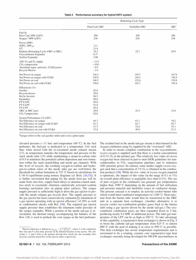
Table 2 summarizes the hybrid system performance includingthe overall impact to the system when accounting for the energyrequirements of carbon capture and storage. CCS in this paperincludes CO2 separation via water knockout and a conventionalwater absorbent, and CO2 compression to pipeline sequestrationconditions of 150 bar [32]. Energy requirements for regenerationof the water sorbent and pumping of the coolant flow for the waterknockout heat exchanger are unknown, but assumed to be 5% ofthe CO2 compression power for the purposes of this study. The
power plant generates 156 MW of net ac power, where the rede-signed FT8 and the scaled-up UTC Power PureCycle sub-systemscontributing nearly 20 MW each. The SOFC operates nominallyat 775 �C with an average cell voltage of 0.75 V, a fuel utilizationof 80%, a power density of 0.45 W/cm2, a 100 �C temperature riseacross both the anode and the cathode, and a 2.5 kPa pressuredrop across the cathode. The SOFC power block provides about68% of the total gross power from the plant, the gas turbine andscaled-up ORC systems supply approximately 13 and 12%,respectively, and the gas expanders about 7%. The compressionof CO2 using intercooled compression stages each at 82% isen-tropic efficiency [24] to sequestration-ready pressure levelsrequires about 10 MW of power. The LPC, LPT, and PT operateat 84.0, 91.8, and 85.8% isentropic efficiencies, respectively. Therecycle blower operates at 50% efficiency (52.6% isentropic) andconsumes about 2.4 MW of power for a cathode recycle ratio of4.6 and a cathode recycle loop pressure rise requirement of 3 kPa.Efficiencies reported in Table 2 are total efficiencies, that is, theyinclude motor and mechanical inefficiencies. Thus, in the case ofthe FT8 turbines and CO2 compressor, the mechanical efficiencyis approximated to nearly 100%.
The net system efficiency of the power plant employing themodified PureCycle ORC bottoming cycle is 65.7% (LHV) whenoperating from clean syngas supplied at the fuel preheater inlet,and 51.5% on raw coal (i.e., accounting for the inefficiency in thegasifier). Syngas-based system performance includes the power
Fig. 6 Effect of cell voltage on system parameters associated with the hybridIGFC system
Journal of Engineering for Gas Turbines and Power FEBRUARY 2012, Vol. 134 / 021801-9
Downloaded 14 Dec 2011 to 138.67.11.94. Redistribution subject to ASME license or copyright; see http://www.asme.org/terms/Terms_Use.cfm

generated from the oxycombustor expander, but not the syngasexpander, and includes the power required to supply O2 to theoxycombustor (1.7 MW). The total system performance afterincluding the energy requirements for CCS reduces the net systemefficiency to 61.3 and 47.8% when based on clean syngas and rawcoal feedstocks, respectively. The use of the P&W ORC Turbo-Den product line offers a bottoming cycle efficiency improvementof 3.5% and increases the net efficiency of the system on syngasto 67.1% and to 49.0% on coal with CCS. These IGFC plantsusing ORC bottoming cycles with CCS amount to 14.0 and 15.2percentage point improvements in efficiency, respectively, overconventional IGCC/CCS power plant performance (estimated at�33.8%-LHV in Ref. [1].).
The high-grade thermal energy that is available for input intothe ORC subsystem suggests that a steam-based rankine powersubsystem is also viable. Indeed, while the purpose of this studywas to investigate the performance with primarily ORC systems, asteam turbine plant potentially offers even higher efficiencydepending on the boiler pressure and superheat temperaturesachievable. Assuming a simple rankine cycle net efficiency of31%, the IGFC system efficiency on coal could produce about10.6 MW of additional power and increase net system efficiencyby 3.7-percentage points to 55.1% (51.5% with CCS).
5.1 IGFC Parameter Sensitivity Study. Having establishedthe baseline performance, select system parameters were varied
and the sensitivity of these parameters to the baseline IGFC sys-tem was evaluated. Cell voltage, fuel utilization, system pressureratio, anode S/C ratio, cathode-side pressure drop, and stack DTwere the system parameters varied. The dc power from the stackwas fixed at 115 MW throughout this study. Given a cell planformand a fixed number of cells per stack, the number of stacks is thencalculated based on design voltage, and overall power setting.This provides an estimate of fuel cell power density. Figures 6–11present trends in system performance metrics such as efficiency,number of stacks required, total power from the gas turbine sys-tem, power obtained from the PureCycle ORC unit, and recycleblower parasitic power as functions of the different parameters.Importantly, in order to separate out the gasifier efficiency consid-erations, the efficiency reported in the following analyses is thenet system efficiency from syngas without CCS penalties.
Figure 6 illustrates the effect of cell voltage on system effi-ciency, power density (as reflected by the number of cell-stacks),and parasitic power in the system. An increase in voltage resultsin lower blower parasitic power, as well as, as a reduction in totalpower produced by the FT8 and PureCycle ORC systems. Reduc-tions in power output from the bottoming cycles occur becauseincreasing cell voltage translates into increasing cell-stack effi-ciency, and correspondingly lower quantities of waste heat in theproduct gas. It is interesting to observe that stack power density isnearly halved by an increase in cell voltage of only 100 mV. Suchhigh sensitivity of power density to changes in cell voltage is
Fig. 7 Effect of fuel utilization on system parameters associated with the hybridIGFC system
021801-10 / Vol. 134, FEBRUARY 2012 Transactions of the ASME
Downloaded 14 Dec 2011 to 138.67.11.94. Redistribution subject to ASME license or copyright; see http://www.asme.org/terms/Terms_Use.cfm

explained by the cell V-j performance characteristic previouslygiven in Fig. 4. For example, at 0.7 V, the single-cell power den-sity is approximately 0.53 W/cm2. At 0.8 V, the power density isabout 0.27 W/cm2. Thus, while high-performance, high powerdensity cell-stacks can be cheaper and more efficient, the shallowslope of their V-j characteristic is such that small changes in volt-age result in large changes in operating current.
The effect of fuel utilization on performance is shown in Fig. 7.At a prescribed cell voltage, system efficiency is correlated withfuel utilization as is ORC power production. The increase in netsystem efficiency is off-set by reductions in FT8 and ORC powerproduction. The power density of the SOFC is also lowered withincreasing fuel utilization as revealed in the figure by the increas-ing number of SOFC stacks required. Interestingly, net powerfrom the FT8 gas turbine system reaches a maximum at a fuel uti-lization of 70%. Further increases in gas turbine power productionwith decreasing fuel utilization are constrained by turbine inlettemperature limits. Increases in SOFC fuel utilization lower theenergy available in the tail-gas and thereby, lower the power out-put of the FT8. The bottoming ORC power output is directly cor-related with fuel utilization and as expected, decreases withincreasing fuel utilization due to lower available thermal energyassociated with the burner outlet stream.
Operating the power plant system at elevated pressure is veryimportant to achieving SOFC power density goals of 0.45 W/cm2,as Fig. 8 shows. Net system efficiency also benefits substantially
(�3.5 percentage points) when increasing the system pressurefrom 3 to 5.2 bar operation. The cathode recycle blower powerparasitic decreases substantially (�43%) in response to increasesin system operating pressure due to reductions in hot gas densityand hence, volume flow rate. However, the primary factors thatenable higher system efficiency from increasing the system pres-sure arise from higher efficiency SOFC and FT8 gas turbine oper-ation. Higher efficiency SOFC operation in response to elevatedpressure is well-documented (e.g., Ref. [36]). The FT8 producessome 57% more net power by design point allowing the LPT shaftpower to increase incrementally more than the increase in theLPC power consumption.
The presence of carbon monoxide (CO) in the dry coal-gasstream delivered to the power plant requires consideration of cok-ing formation side reactions within piping runs and hardware. Inparticular, as noted by Probstein and Hicks [33], fuel gas mixtureswith O/C ratios of 1.0 and H/C ratios of 2 are likely to form car-bon in the temperature range between 625–925 �C. The Bou-douard coking mechanism can be inhibited and/or controlled withsteam injection. The approach taken in the system design effortsto limit the potential for undesirable coke formation is centered ona two-pronged strategy where (1) fuel gas piping is lined withcopper or oxide layers that minimize nucleation sites for coke for-mation and (2) injecting steam (albeit at a lower steam-to-carbonratio) into the fuel syngas stream via an ejector and anode gasrecycle. Since the coal fuel gas provided by the gasifier is
Fig. 8 Effect of system pressure ratio on system parameters associated with thehybrid IGFC system
Journal of Engineering for Gas Turbines and Power FEBRUARY 2012, Vol. 134 / 021801-11
Downloaded 14 Dec 2011 to 138.67.11.94. Redistribution subject to ASME license or copyright; see http://www.asme.org/terms/Terms_Use.cfm

significantly pressurized, the ejector can be effectively driven toprovide the desired recycle flows.
Figure 9 relates the effect of steam-to-carbon (SC) ratio on sys-tem performance. Note again that as with the previous analyses,the design cell voltage has been fixed in this parameter variation.One of the main effects of increasing SC ratios is the reduction inSOFC power density due to dilution of the anode gas feed andhence, a lowering of the Nernst potential. This dramaticallyincreases the number of fuel cell stacks required to deliver 115MW of power. The overall system efficiency is also correlatedwith the amount of anode recycle (and hence, SC). Interestingly,the increase in SC ratio produces an increase in system efficiencyeven though the bottoming cycle power production is reduced.The root of this performance change is related to an increase ineffective system fuel utilization. In this analysis, the per-pass (orin-cell) fuel utilization was held constant at 80%. The increase inrecycle actually increases the overall system fuel utilization. Thus,the system efficiency trends with increasing SC are not unlikethose of increasing per pass fuel utilization within the SOFC(although the concavity of the plots is different).
Figures 10 and 11 depict the sensitivity of cathode side pressuredrop and temperature rise on system performance, respectively.While the recycle blower parasitic power appears to be stronglyinfluenced by cathode loop pressure drop, it is actually a relativelymild effect when considering pressurized gas flows and the per-
centage of net power production from the plant. There is a muchstronger system-level efficiency effect associated with cathodepressure drop in near-ambient pressure SOFC systems (i.e., 1.0 to1.1 bar). Cathode temperature rise has a direct influence on SOFCpower density due to increases in per pass oxidant utilization asFig. 11 shows, but the system efficiency and net power productionfrom the ORC are only mildly affected. The net FT8 power pro-duction is slightly decreased due to the reduction in mass flowthrough the unit. While cathode temperature rise can provide sub-stantial blower parasitic power reductions, greater system effi-ciency advantages can be obtained with increases in celltemperature [37].
6 Summary
Overall, while efficiency is reasonably correlated to fuel utili-zation, system pressure and anode S/C ratio, the number ofstacks required to achieve 115 MW from the SOFC system issensitive to each of these parameters. An optimal selection of pa-rameters is possible if cost data are available. This has not beenattempted in the current study, and will be considered in futurestudies.
Given that the parametric analyses did not include the gasifiertechnology and performance, system integration advantages maybe overlooked. In general, by fixing the SOFC stack power, the
Fig. 9 Effect of anode S/C ratio on system parameters
021801-12 / Vol. 134, FEBRUARY 2012 Transactions of the ASME
Downloaded 14 Dec 2011 to 138.67.11.94. Redistribution subject to ASME license or copyright; see http://www.asme.org/terms/Terms_Use.cfm

results and trends of the study are constrained by the interactionsbetween SOFC stack, gas turbine, and ORC subsystems. For exam-ple, an increase in SOFC efficiency via design operating cell volt-age increase, results in a decrease of reactant gas flows to the gasturbine and thereby lowering its output power. Alternatively, ena-bling the means for fixing gas turbine flow via either supplementalsyngas firing or utilizing nitrogen available from the ASU couldprovide improved net system performance. Additional considera-tions include (1) integrating the FT8 low-pressure compressor withthe ASU, (2) syngas firing to maintain FT8 gas turbine inlet temper-ature as close to 950 �C as possible subject to 90% carbon captureconstraints, (3) recuperation of syngas cleanup cooling loads to theORC unit, and (4) examination of catalytic gasification technologywhich has as much as a 10 percentage point cold-gas efficiencyadvantage over entrained-flow gasification systems.
Nevetheless, the present study does reveal that entrained-flowgasifiers with oxycombustion system configurations can indeedlead to high power plant efficiencies. It also quantifies the effect ofSOFC pressurization in the 3–5 bar range on system performance.It is worthwhile to note that these results have been obtained byusing actual FT8 performance maps and SOFC performance basedon near-term planar technology. In this study, a parametric sensitiv-ity study was conducted on a given system configuration. It is notclear if the proposed system is the best possible design. However,the combined effect of selecting more “optimal” SOFC stack oper-ating parameters, such as increasing cell voltage to 0.8V, cathodetemperature rise to 150 �C, and decreasing per pass cell utilization
(while maintaining overall fuel utilization) is expected to increasesystem performance by 3 percentage points or more.
7 Conclusions
This study detailed the performance of a 100 MW-scale IGFChybrid power plant that integrated a pressurized SOFC powerblock with the low-pressure turbine spool of the Pratt & WhitneyFT8-3 gas turbine and either a scaled-up, water-cooled version ofthe P&W PureCycle ORC or the larger P&W TurboDen productlines. The basic system concept included carbon capture via oxy-combustion followed by water knockout and CO2 compression topipeline ready CO2 sequestration conditions. Performance resultswere reported that indicate hybrid SOFC systems could achieveelectric efficiencies of 49% including CCS and as high as 67%when operating off a clean syngas and venting the CO2 to theatmosphere. The impact of integrating an ORC bottoming cyclewas found to add as much as 8 percentage points of efficiency tothe system. Use of a steam power cycle, in lieu of the ORC, couldincrease net plant efficiency by another 3.7%. Additionally, thestrategic use of gas expanders is particularly advantageous to off-set carbon capture compression requirements or air separation unitparasitic power requirements.
A study of system performance sensitivity to a variation inSOFC design parameters revealed the strongest influences aredesign cell voltage, SOFC fuel utilization, and system pressure.The net system efficiency can vary by as much as 3 percentage
Fig. 10 Effect of cathode-side pressure drop on system parameters
Journal of Engineering for Gas Turbines and Power FEBRUARY 2012, Vol. 134 / 021801-13
Downloaded 14 Dec 2011 to 138.67.11.94. Redistribution subject to ASME license or copyright; see http://www.asme.org/terms/Terms_Use.cfm

points over the range studied for changes to any of these parame-ters. Anode tail gas recycle ratio and cathode side design parame-ters, such as pressure drop and temperature rise, only mildly affectsystem efficiency; however, increasing the recycle ratio of anodetail-gas has the negative effect of decreasing SOFC power densityand hence, increasing the number of cell-stacks required. Depend-ing on power density, two to three thousand SOFC stacks arerequired to generate 115 MW of dc power. Technoeconomic anal-ysis could identify optimal stack design parameters.
It was also noted that additional analyses related to changes inthe system design, such as ASU integration with the gas turbine orcatalytic gasification could substantially improve the system per-formance beyond what is reported herein.
Acknowledgment
The authors would like to thank Pamela McNary, Bruce Wen-dus, and Joe Hilmon at Pratt & Whitney for their assistance ingenerating performance maps and engineering modifications tothe FT8-3 gas turbine power system, and Lili Zhang at UnitedTechnologies Research Center for her helpful information onP&W PureCycle performance characteristics. This paper was pre-pared with the support of the U.S. Department of Energy, underAward Nos. DE-FC26-02NT41246 and DE-NT0005202. How-ever, any opinions, finding, conclusions, or recommendationsexpressed herein are those of the authors and do not necessarilyreflect the views of the DOE.
References[1] Klara, J. M., 2009, “The Potential of Advanced Technologies to Reduce Carbon
Capture Costs in Future IGCC Power Plants,” Energy Procedia, 1, 3827–3834.[2] Santin, M., Traverso, A., and Massardo, A., 2008, “Technological Aspects of
Gas Turbine and Fuel Cell Hybrid Systems for Aircraft: A Review,” The Aero-naut. J., 112(1134), pp. 459–467.
[3] Costamagna, P., Magistri, L., and Massardo, A., 2001, “Design and Part-LoadPerformance of a Hybrid System Based on a Solid Oxide Fuel Cell Reactor anda Micro Gas Turbine,” J. Power Sources, 96, 352–368.
[4] Roberts, R., Brouwer, J., Jabbari, F., Junker, T., and Ghezel-Ayagh, H., 2006,“Control Design of an Atmospheric Solid Oxide Fuel Cell/Gas Turbine HybridSystem: Variable Versus Fixed Speeed Gas Turbine Operation,” J. Power Sources,161, 484–491.
[5] Traverso, A., Massardo, A., Roberts, R., Brouwer, J., and Samuelsen, S., 2007,“Gas Turbine Assessment for Air Management of Pressurized SOFC/GTHybrid Systems,” ASME J. Fuel Cell Sci. Technol., 4, 373–383.
[6] Ferrari, M., 2011, “Solid Oxide Fuel Cell Hybrid System: Control Strategy forStand-Alone Configurations,” J. Power Sources, 196, 2682–2690.
[7] Yang, J. S., Sohn, J. L., and Ro, J., 2007, “Performance Characteristics of aSolid Oxide Fuel Cell/Gas Turbine Hybrid System With Various Part-LoadControl Modes,” J. Power Sources, 166, 155–164.
[8] Mueller, F., Gaynor, R., Auld, A., Brouwer, J., Jabbari, F., and Samuelsen, G.,2008, “Synergistic Integration of a Gas Turbine and Solid Oxide Fuel Cell forImproved Transient Capability,” J. Power Sources, 176, 229–239.
[9] Tucker, D. Lawson, L., and Gemmen, R., 2005, “Characterisation of Air FlowManagement and Control in a Fuel Cell Turbine Hybrid Power System UsingHardware Simulation,” ASME Paper No. PWR2005-50127.
[10] Research and Development Solutions, LLC, 2007, “Cost and PerformanceBaseline for Fossil Energy Plants,” Final Report, U.S. DOE, National EnergyTechnology Laboratory, DOE/NETL-2007/1281, August, Vol. 1.
[11] Lobachyov, K., and Richter, H. J., 1996, “Combined Cycle Gas Turbine PowerPlant With Coal Gasification and Solid Oxide Fuel Cell,” J. Energy Res. Tech-nol., 118, 285–292.
Fig. 11 Effect of stack DT on various system parameters in the hybrid IGFCsystem
021801-14 / Vol. 134, FEBRUARY 2012 Transactions of the ASME
Downloaded 14 Dec 2011 to 138.67.11.94. Redistribution subject to ASME license or copyright; see http://www.asme.org/terms/Terms_Use.cfm

[12] Kivisaari., T., Bjornbom, P., Sylwan, C., Jacquinot, B., Jansen, D., and deGroot, A., 2004, Chem. Eng. J., 100, 167–180.
[13] Ghosh, S., and De, S., 2006, “Energy Analysis of a Cogeneration Plant UsingCoal Gasification and Solid Oxide Fuel Cell,” Energy, 3, 345–363.
[14] Verma, A., Rao, A. D., and Samuelsen, G.S., 2006, “Sensitivity Analysis of a Vision21 Coal Based Zero Emission Power Plant,” J. Power Sources, 158, 417–427.
[15] Romano, M., Campanari, S., Spallina, V., and Lozza, G., 2009, “SOFC-BasedHybrid Cycle Integrated With a Coal Gasification Plant,” ASME Paper No.GT2009-59551.
[16] Liese, E., 2010, “Comparison of Preanode and Postanode Carbon DioxideSeparation for IGFC Systems,” ASME J. Eng. Gas Turbines Power, 132,061703.
[17] Siefert, N., Shekhawat, D., and Kalapos, T., 2010, “Integrating Catalytic CoalGasifiers With Solid Oxide Fuel Cells,” ASME Paper No. FC2010-33206.
[18] Gerdes, K., Grol, E., Keairns, D., and Newby, R., 2009, “Integrated GasificationFuel Cell Performance and Cost Assessment,” Report No. DOE/NETL-2009/1361, March, National Energy Technology Laboratory, Morgantown, WV.
[19] Verda, V., 2008, “Solid Oxide Fuel Cell System Configurations for DistributedGeneration,” ASME J. Fuel Cell Sci. Technol., 5, 041001.
[20] Shelton, W., and Lyons, J., 2000, “Shell Gasifier IGCC Base Cases,” PED-IGCC-98-002, revised, prepared by EG&G for the U.S. Department of Energy, Office ofFossil Energy, National Energy Technology Laboratory, Morgantown, WV.
[21] Pratt & Whitney Power Systems, 2010, “Organic Rankine Cycle Technology,”product brochure, PS-S0022.01.10, available from www.pw.utc.com
[22] Process Systems Enterprise, Ltd., 2009, http://www.psenterprise.com/gproms/index.html, as accessed on 11/2015/2006.
[23] Simbeck, D. R., Korens, N., Biasca, F. E., Vejtasa, S., and Dickenson, R. L.,1993, “Coal Gasification Guidebook: Status, Applications, and Technologies,”Electric Power Research Institute Final Report No. TR-102034, Palo Alto, CA.
[24] Chiesa, P., Consonni, S., Kreutz, T., and Williams, R., 2005, Int. J. HydrogenEnergy, 30, 747–767.
[25] West Virginia University Chemical Engineering Department, 2009, “Large-ScaleProcess Design Projects: Air Separation Into Oxygen, Nitrogen and Argon,” http://www.che.cemr.wvu.edu/publications/projects/large_proj/air.PDF, accessed June 1.
[26] American Water Works Association, 1997, Water Treatment Plant Design, 3rded., American Society of Civil Engineers/McGraw Hill, New York.
[27] USDE, 2008, Proceedings of the 9th Annual Solid State Energy ConversionAlliance (SECA) Workshop, U.S. Department of Energy, National EnergyTechnology Laboratory, August 5–7.
[28] Williford, R. E., Chick, L. A., Maupin, G. D., Simner, S. P., and Stevenson,J.W., 2003, J. Electrochem. Soc., 150(8), A1067–A1072.
[29] Pratt & Whitney Power Systems, 2010, “Organic Rankine Cycle Technology,”Product Brochure (PS-S0022.01.10), www.pw.utc.com
[30] GE Power, 2008, “GE Combined Cycle Product Line and Performance,” GEPower Product and Services Website Information, Publication document No.GER3574g.
[31] Farmer, R., ed., 2006, Gas Turbine World Handbook, Pequot, Southport, CT.[32] U.S. DOE, 2005, “Carbon Capture and Sequestration Systems Analysis Guide-
lines,” Office of Fossil Energy, NETL, April.[33] Probstein, R. F., and Hicks, R.E., 2006, Synthetic Fuels, Dover, Mineola, NY.[34] Marsano, F., Magistri, L., and Massardo, A., 2004, “Ejector Performance Influ-
ence on a Solid Oxide Fuel Cell Anodic Recirculation System,” J. Power Sour-ces, 129, 216–228.
[35] Wilson, D. G., 2003, “Regenerative Heat Exchangers for Microturbines, and anImproved Type,” Proceedings of the ASME Turbo Expo 2003, June 16–19,Atlanta, Georgia.
[36] EG&G Technical Services, Inc., 2004, Fuel Cell Handbook, 7th ed., preparedfor the U.S. DOE Office of Fossil Energy, National Energy Technology Labora-tory, Morgantown, WV.
[37] Braun, R. J., 2010, “Techno-Economic Optimal Design of Solid Oxide FuelCell Systems for Micro-Combined Heat and Power Applications in the U.S.,”ASME J. Fuel Cell Sci. Technol. 7, p. 031018.
Journal of Engineering for Gas Turbines and Power FEBRUARY 2012, Vol. 134 / 021801-15
Downloaded 14 Dec 2011 to 138.67.11.94. Redistribution subject to ASME license or copyright; see http://www.asme.org/terms/Terms_Use.cfm