hino trucks body mounting manual - hino.com.co · kcaa201a purpose this manual is provided to body...
TRANSCRIPT

HINO TRUCKS
COMMON to all HinoTruck series
Body Mounting Manual
KC-AA201A

KC-AA201A
No part of this manual may be reproduced or transmitted in any form without the express written permission of Hino Motors, Ltd. © 2012, Hino Motors, Ltd. All rights reserved. Printed in Japan.
3-1-1, HINO-DAI, HINO-SHI, TOKYO, 191-8660 JAPAN
2012 - 12
KC-AA201A
Purpose
This manual is provided to Body and Equipment Manufacturers, including inter-mediate and/or final stage manufacturers (hereinafter collectively referred to as Body and Equipment Manufacturers), to provide :
• Technical instructions for Hino truck chassis with cab for mounting of bodies and alterations of chassis.
• An aid to Body and Equipment Manufacturers for producing safe vehicles under their own discretion and responsibility.
• Other general advice for installation, modification or alteration. when Body and Equipment Manufacturers install any body or other equipment or device on Hino truck chassis with cab (hereinafter collectively referred to as Hino Chassis), or modify or alter a Hino Chassis.
Important
This manual contains the instructions commonly applicable to all Hino truck models.
Peculiar instructions as chassis layout drawings, chassis mass, precautions etc. for each model, are given separately in the peculiar body mounting manuals for each vehicle model (hereinafter collectively referred to as the "Manual for each model").
Therefore, this manual should be used together with the Manual for each model series.(Details of construction of Hino's Body Mounting Manual are mentioned at the last part of this chapter.)
• The Manuals for each model is available at authorized Hino distributor.• For more information on mounting bodies and equipment or on chassis modifications,
refer to the appropriate workshop manuals, parts catalogs, maintenance guides and owner's or driver's manual.
• The information in this manual is accurate to the best of Hino's Knowledge at the time of going to press. Hino reserves the right to modify any and all information without notice and without obligation.
• Should more detailed data or information be needed, please contact authorized Hino distributor.
ABOUT THIS MANUAL
KC-AA201A
Warning
• It is the responsibility of the Body and Equipment Manufacturers or the Modification companies to make sure that the completed vehicle with body and equipment, or after modification, conforms to all applicable laws and regulations of the country in which the vehicle is to be used (e. g. regulations on lighting, tilt, overall size, axle load, external noise control etc.).
• This manual does not guarantee the safety of a Hino chassis which has been installed, modified, or altered by Body and Equipment Manufacturers.
• This manual does not affect that the ultimate responsibility for the manufacture and mounting of the body, installation, modification or alteration on a Hino Chassis devolves upon the Body and Equipment Manufacturer.
• Each individual Body and Equipment Manufacturer has the sole responsibility for the design, functions, materials and work concerning the body and equipment.
• Hino Motors, Ltd. does not assume any liability whatsoever for any injury to persons or damage to property caused as a result of the utilization of this manual.
ABOUT THIS MANUAL
KC-AA201A
ABOUT THIS MANUAL
HINO TRUCKS
COMMON to all HinoTruck series
Body Mounting Manual
KC-AA201A
HINO 500 SERIES
Body Mounting Manual
FD8JMODEL
KK-FD201
TRUCK CHASSISTRUCK CHASSIS
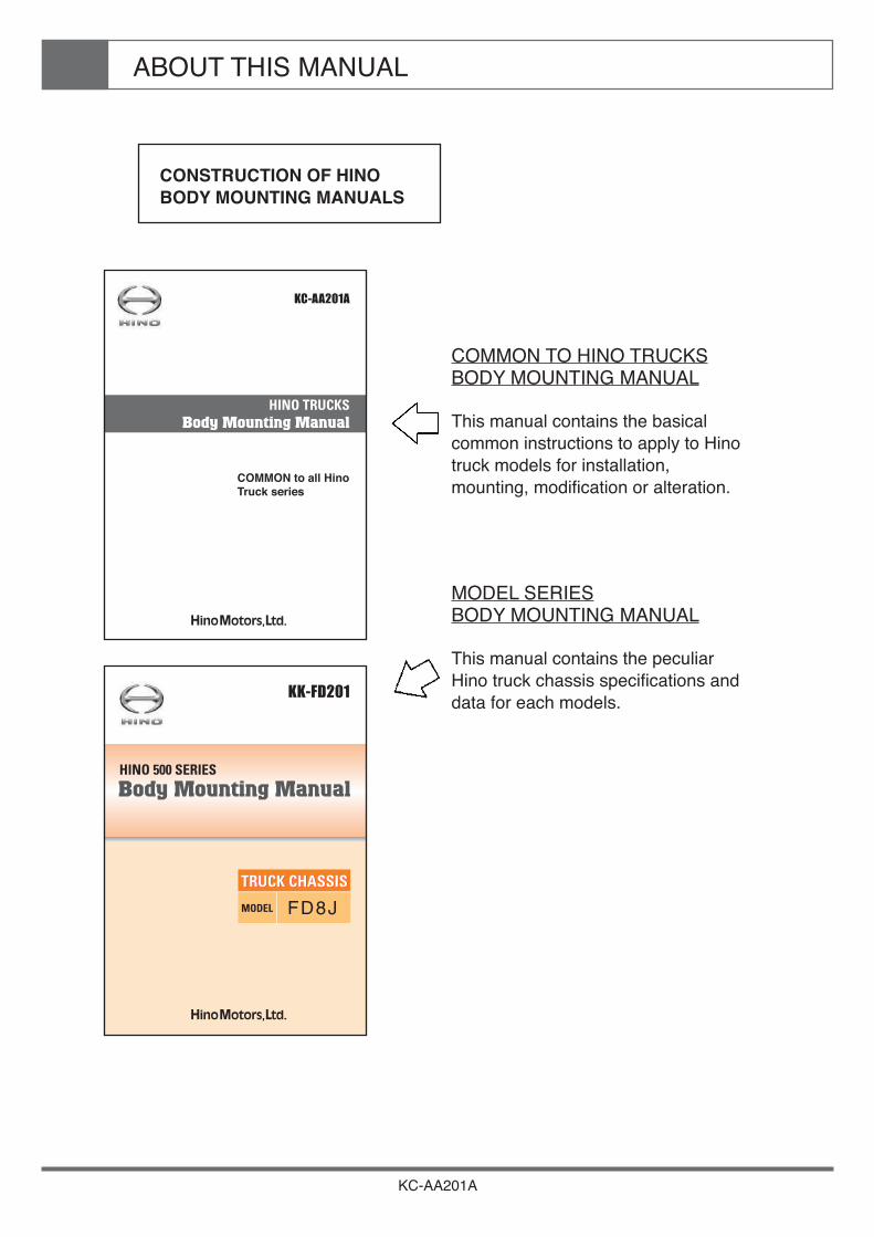
COMMON TO HINO TRUCKSBODY MOUNTING MANUAL
This manual contains the basical common instructions to apply to Hino truck models for installation, mounting, modification or alteration.
MODEL SERIESBODY MOUNTING MANUAL
This manual contains the peculiar Hino truck chassis specifications and data for each models.
CONSTRUCTION OF HINO BODY MOUNTING MANUALS

KC-AA201A
1. GENERAL PRECAUTIONS
2. CHASSIS FRAME
3. ENGINE AND ENGINE COMPARTMENT
4. PROPELLER SHAFT
5. BRAKE & HYDRAULIC PIPING
6. FUEL TANK
7. ELECTRICAL SYSTEM
8. EXHAUST SYSTEM
9. BATTERY
10. SUSPENSION AND TIRE
11. SPARE TIRE CARRIER
12. BODY & EQUIPMENT MOUNTING
13. BODY & EQUIPMENT CONTROLS
14. PAINTING
15. VEHICLE INSPECTION & PROTECTION
CONTENTS

KC-AA201A
Chapter 1GENERAL PRECAUTIONS
1. GENERAL PRECAUTIONS ••••••••••••••••••••••••••••••••••• 2 2. MOUNTING PRECAUTIONS ••••••••••••••••••••••••••••••••• 4 3. BODY DESIGN AND CONSTRUCTION •••••••••••••••••••• 8 4. NEVER MODIFY SAFETY PARTS •••••••••••••••••••••••••• 24 5. CLEARANCES •••••••••••••••••••••••••••••••••••••••••••••••••• 28 6. FIRE SHIELD ••••••••••••••••••••••••••••••••••••••••••••••••••••• 39 7. ACCESSIBILITY FOR MAINTENANCE •••••••••••••••••••• 40 8. APPROACH AND DEPARTURE ANGLES •••••••••••••••• 41 9. EXTERNAL NOISE CONTROL PARTS •••••••••••••••••••• 42 10. AVOIDING DAMAGE TO CHASSIS ••••••••••••••••••••••••• 43 11. LEAF ADDITIONS •••••••••••••••••••••••••••••••••••••••••••••• 43 12. SHIPMENT •••••••••••••••••••••••••••••••••••••••••••••••••••••••• 43 13. TOWING VEHICLES •••••••••••••••••••••••••••••••••••••••••••• 43 14. COMPLYING WITH LAWS AND REGULATIONS •••••••• 43 15. PREPARATION OF OPERATION MANUAL AND/OR
MAINTENANCE & INSPECTION ••••••••••••••••••••••••• 44 16. ESTABLISHING AFTER-SALE SERVICE SYSTEM ••••• 44 17. TRACTOR VEHICLE ••••••••••••••••••••••••••••••••••••••••••• 45
GENERAL PRECAUTIONS1
KC-AA201A 1
This section describes general precautions that must be taken when mounting a standard body or equipment or when making alterations to the chassis.
Improper mounting of a body or equipment or improper alterations may cause unforeseen faults in the vehicle and lead to serious accidents.
If you intend to mount a body or equipment, or make alterations to the chassis of a HINO vehicle, be sure to observe the precautions described in this section.

GENERAL PRECAUTIONS1
KC-AA201A 2
1. GENERAL PRECAUTIONS
Before Mounting and Alterations
The base vehicle has been proved for laws and regulations, performance, and safety, becoming a well-rounded vehicle. Pay particular attention not to impair its functions by mounting and alterations.
Thoroughly review the mounting and alteration methods and the modification to be made to the standard parts through alteration, and verify the result of the review to see if there is no technical and safety problems.
Laws and regulations related to the mounting and alterations place the minimum restrictions. In making alterations to vehicle, care should be taken to design and fabricate them in such a manner as to satisfy various related law and regulations with an ample allowance.
Be sure that the materials used for mounting or alterations sufficiently meet the legal requirements, the performance and safety standards, and that the resulting vehicle should be as light weight as possible.
No difference in weight between right and left wheels should occur due to the mounting or alterations.
The materials and parts involved in the mounting or alteration work should be designed and fabricated to facilitate the inspection and maintenance of chassis parts after they are mounted on the vehicles.
Forward field of view must not be restricted by mounting or alterations.
During Mounting and Alterations
Be sure that the work not to damage the chassis or impair its functions.
When removing and reinstalling chassis components, be sure to follow the procedures described in the Workshop Manual issued by Hino Product Support Division.
All mounting job should be conducted in a manner avoiding local concentration of the load on the chassis frame. In order to distribute the load over the frames, all the wheels should be located on the same plane without distorting the frame.
Never make any modification (welding, padding, machining, heating, etc.) to the component parts of the important safety parts (accelerator, steering, brake, suspension, etc.)

GENERAL PRECAUTIONS1
KC-AA201A 3
After Mounting and Alterations
Check to see whether the materials or parts used for such work are produced as designed and satisfy predetermined performance requirements and functions, and also whether they contain no defects.
If the handling, maintenance, and service methods change due to mounting and alterations, prepare the Instruction Manual and attach it to the completed vehicle.
Prepare Instruction Manuals, Service Guides, and so on about the handling and maintenance, service of the rear body or equipment as well as the inspection interval and attach them to the completed vehicle.
Pay every attention to the after-sales service system for the mounted body and alteration parts. Workshop Manuals of Hino chassis are optionally available from your local Hino Distributor.

GENERAL PRECAUTIONS1
KC-AA201A 4
2. MOUNTING PRECAUTIONS
Requests to Body and Equipment Manufacturers
Pay extra attention to safety of products in the design, fabrication, and inspection phases.
Design ensuring safety All products must be proven for safety and equipped with safety devices as required. (Specifically, the parts that may come into contact with the human body must be provided with this measure.) The “industry-standard levels and safety of other products” should also be taken into account.
Fabrication conforming to drawings Quality of the fabricated products should conform to the instructions given in the drawings. (Prevention of wrong parts, missing parts, and assembly defects.)
Final inspection Conduct final inspection for all products and prepare Inspection Records.
Storage and management of drawings, documents, and Inspection Records. Set up the rules for storing the drawings, documents, and inspection Records concerning a. to c. and make them understood.
Prepare substantial Instruction Manuals and WARNING labels
Instruction Manual Describe the effects of improper handling and usage upon the customer body and vehicle to details as Precautions.
Warning Labels Describe safety notes on labels as briefly as possible and affix them at appropriate positions.
Precautions to Follow when Studying and designing body and Equipment
When studying and designing the installation of body and equipment, note the following ;
Observe the safety regulations, inspection standards, and other standards concerning the vehicle.
If there are self-imposed control rules set up by the Automobile Manufacturer’s Association, Vehicle Body Industrial Association, and so on, follow them.
Pay extra attention to vehicle safety and prevention of accidents.
GENERAL PRECAUTIONS1
KC-AA201A 5
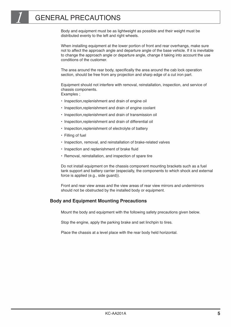
Body and equipment must be as lightweight as possible and their weight must be distributed evenly to the left and right wheels.
When installing equipment at the lower portion of front and rear overhangs, make sure not to affect the approach angle and departure angle of the base vehicle. If it is inevitable to change the approach angle or departure angle, change it taking into account the use conditions of the customer.
The area around the rear body, specifically the area around the cab lock operation section, should be free from any projection and sharp edge of a cut iron part.
Equipment should not interfere with removal, reinstallation, inspection, and service of chassis components. Examples ;• Inspection,replenishment and drain of engine oil• Inspection,replenishment and drain of engine coolant• Inspection,replenishment and drain of transmission oil• Inspection,replenishment and drain of differential oil• Inspection,replenishment of electrolyte of battery• Filling of fuel• Inspection, removal, and reinstallation of brake-related valves• Inspection and replenishment of brake fluid• Removal, reinstallation, and inspection of spare tire
Do not install equipment on the chassis component mounting brackets such as a fuel tank support and battery carrier (especially, the components to which shock and external force is applied (e.g., side guard)).
Front and rear view areas and the view areas of rear view mirrors and undermirrors should not be obstructed by the installed body or equipment.
Body and Equipment Mounting Precautions
Mount the body and equipment with the following safety precautions given below.
Stop the engine, apply the parking brake and set linchpin to tires.
Place the chassis at a level place with the rear body held horizontal.
GENERAL PRECAUTIONS1
KC-AA201A 6
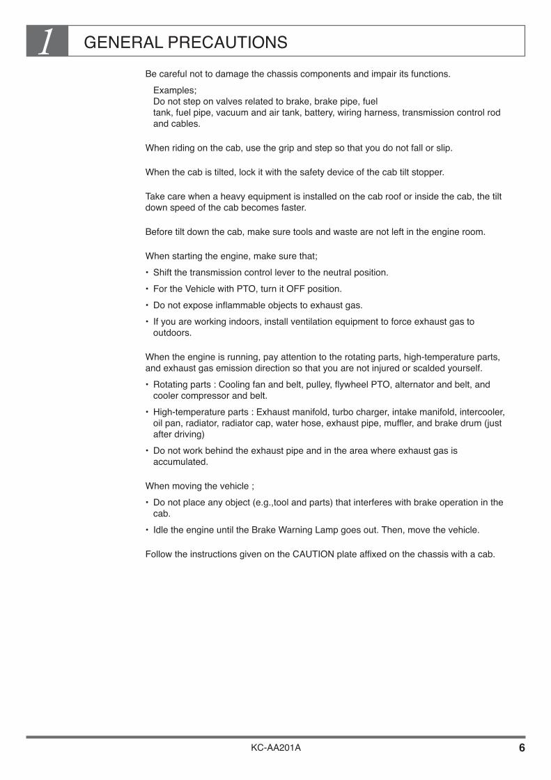
Be careful not to damage the chassis components and impair its functions. Examples;
Do not step on valves related to brake, brake pipe, fuel tank, fuel pipe, vacuum and air tank, battery, wiring harness, transmission control rod and cables.
When riding on the cab, use the grip and step so that you do not fall or slip.
When the cab is tilted, lock it with the safety device of the cab tilt stopper.
Take care when a heavy equipment is installed on the cab roof or inside the cab, the tilt down speed of the cab becomes faster.
Before tilt down the cab, make sure tools and waste are not left in the engine room.
When starting the engine, make sure that;• Shift the transmission control lever to the neutral position.• For the Vehicle with PTO, turn it OFF position.• Do not expose inflammable objects to exhaust gas.• If you are working indoors, install ventilation equipment to force exhaust gas to
outdoors.
When the engine is running, pay attention to the rotating parts, high-temperature parts, and exhaust gas emission direction so that you are not injured or scalded yourself.• Rotating parts : Cooling fan and belt, pulley, flywheel PTO, alternator and belt, and
cooler compressor and belt.• High-temperature parts : Exhaust manifold, turbo charger, intake manifold, intercooler,
oil pan, radiator, radiator cap, water hose, exhaust pipe, muffler, and brake drum (just after driving)
• Do not work behind the exhaust pipe and in the area where exhaust gas is accumulated.
When moving the vehicle ;• Do not place any object (e.g.,tool and parts) that interferes with brake operation in the
cab.• Idle the engine until the Brake Warning Lamp goes out. Then, move the vehicle.
Follow the instructions given on the CAUTION plate affixed on the chassis with a cab.

GENERAL PRECAUTIONS1
KC-AA201A 7
When reinstalling wheels, be sure to tighten wheel nuts to the specified tightening torque.• However, the tightening torque differs from one vehicle type to another depending upon
the quantity, diameter, tightening method (i. e. ISO, SAE or JIS TYPE) of the stud bolts in use.
• Therefore, read your Owner's or Workshop Manual carefully and securely tighten the wheel nuts.
About Headlamp Aiming Adjustment
The vehicle posture changes after installation of body and equipment. Carry out headlamp aiming adjustment. (For the adjustment procedure, refer to the Owner’s or Workshop Manual.)
About Fog Lamp, etc. Aiming Adjustment
When a vehicle is equipped with a body and other equipment, the vehicle posture tends to change. Therefore, adjust, if necessary, the aiming of fog lamps, back-up lamps, etc. Particularly, in such countries where restrictions are imposed due to road regulation, carry out the said adjustment so that the requirements can be satisfied.
About LSV Adjustment
The vehicle posture and ground clearance change after installation of body and equipment. Adjust the LSV. However, LSVs are fitted on some models while they are not on some others. Also, the adjustment is not required on some versions. Be sure to make the said adjustment if necessary by referring to your Owner's or Workshop Manual.
Precautions for Adjusting the Tire Air Pressure
When the chassis with cab is delivered, the tire air pressure is reduced to absorb the shocks and vibrations caused during transportation by road. After completion of mounting, adjust the tire air pressure. (For the correct air pressure, refer to the Owner's or Workshop Manual. )

GENERAL PRECAUTIONS1
KC-AA201A 8
3. BODY DESIGN AND CONSTRUCTION
ENSURING TOTAL VEHICLE QUALITY
The final quality of a vehicle depends not only on the chassis manufacturer but also on the body manufacturer. Accordingly, body manufacturers should pay attention to the following aspects of body design and construction.
GENERAL PRECAUTIONS1
KC-AA201A 9
Mass and Dimensions
When designing or constructing a body, make sure that;• the total mass of the vehicle is within the permissible axle capacity, tire capacity and
gross vehicle mass (GVM).• the front axle load satisfies the minimum ratio of gross vehicle mass.• the height of the center of gravity from the ground after body mounting is within the
specified limit.• the vehicle mass is evenly distributed between left and right wheels.• the overall width of the vehicle is within the specified limit.• the dimensions and mass of the vehicle comply with local regulations.
The specified values for the above items are given under “1.Vehicle summary—Chassis Specifications” in the Hino Body Mounting Manual for the respective model series. For your reference, example of the chassis specifications to be given in the Body Mounting Manual for the respective model series is described in the next page.

GENERAL PRECAUTIONS1
KC-AA201A 10
Example : VEHICLE SUMMARY
CHASSIS SPECIFICATIONS
NOTE• Permissible axle and GVM capacities must not exceed the values
listed in the above table.
• The front axle load must exceed 30% of the gross vehicle mass under full loaded condition.
• The height of center of gravity from ground on the unloaded vehicle with body mounted should be 1.21 m or less.
• Weight distribution on the left and right wheels should be balanced.
• Both front axle and rear axle loads must not exceed the permissible load based on the tire load capacity according to the tire standards in your country.
GH1JJKA
4,280
JIS GROSS
ISO NET
JIS GROSS
ISO NET
STD
OPT
STD
STD
1,915
1,840
16,500
6,000
10,500
J08C-F
150kW {204PS} at 2,900r/min
546N·m {55.7kgf·m} at 1,500r/min
10.00-20-16PR
10.00R20-16PR
20 X 7.00T-offset 162mm
200
12V-234kC {65A·h} -2
24V-50A
Less than 2,460
Item Chassis model
Wheel base (mm)
Tread
Max.GVM Capacity
Front
Rear
Engine
Model
Max. Output
Max. Torque
Height of center of gravity
Tire and Disc
Tire
Disc
Fuel tank
Battery
Alternator
Recommended maximum body width
Permissibleaxle capacity
Chassis mass on STD specifications
(including water, oil and full fuel)
(mm)
(L)
(m)
(kg)
(kg)
Front
Rear (kg)
(kg)
Total (kg)
Front
Rear (kg)
(kg)
(kg)
4,970
3,045
1,925
0.830

GENERAL PRECAUTIONS1
KC-AA201A 11
Formulae for Calculation (For Single Vehicle)
When calculating• gross vehicle mass• body load center (offset), and• height of center of gravity from ground for chassis with body mounted, use the formulae
described in this section.
Gross Vehicle Mass (GVM)
What is Gross Vehicle Mass (GVM) ;

GENERAL PRECAUTIONS1
KC-AA201A 12
Basic Formulae for Mass Distribution
The distribution of mass on front and rear axles is calculated as follows;
For one unit of load
For multiple units of load
GENERAL PRECAUTIONS1
KC-AA201A 13
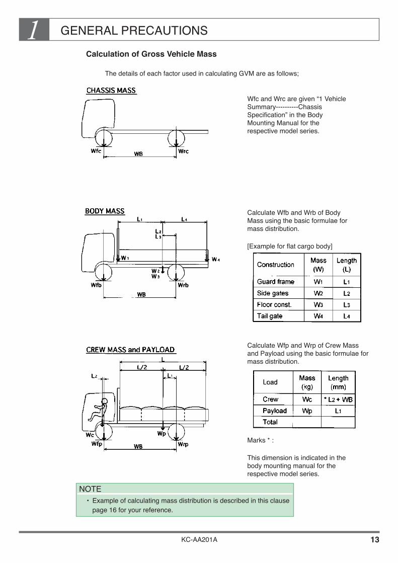
Calculation of Gross Vehicle Mass
The details of each factor used in calculating GVM are as follows;
Wfc and Wrc are given “1 Vehicle Summary----------Chassis Specification” in the Body Mounting Manual for the respective model series.
Calculate Wfb and Wrb of Body Mass using the basic formulae for mass distribution.
[Example for flat cargo body]
Calculate Wfp and Wrp of Crew Mass and Payload using the basic formulae for mass distribution.
Marks * :
This dimension is indicated in the body mounting manual for the respective model series.
NOTE• Example of calculating mass distribution is described in this clause
page 16 for your reference.

GENERAL PRECAUTIONS1
KC-AA201A 14
Theoretical Calculation of Body Load Center (Offset)
Calculation of carrying capacity (CC)
CC = GVMR – (Chassis mass + Crews mass) = Body mass + Payload
For a Model GH1JJKA Cargo Truck (kg)
Calculation of carrying capacity load center
As carrying capacity load center is fixed, mountable body length can be calculated.
L = 2,265 x 2 = 4,530 mm
Actual body offset is determined by the body length required by customer and maximum permissible rear-overhang length.

GENERAL PRECAUTIONS1
KC-AA201A 15
Mass Distribution on Front Axle (When loaded)
This means the percentage of vehicle total mass applied on front axle.
Limit : Front axle mass Distribution ≥ 30%
(For instance 4x2, 4x4 or 8x4 vehicle)
The mass distribution on front axle has also a major impact on the steering and handling of the vehicle. Therefore on safety during running, make sure that the minimum 30% of vehicle total mass applied on front axle.
NOTEDesired value for each type of vehicle as described following table.
Front Axle Mass
Gross Vehicle Massx 100 ≥ 30%
4 x 2
MASS DISTRIBUTION ON FRONTAXLE (WHEN LOADED / UNIT : %)DRIVE ( : DRIVE AXLE)
4 x 4 30
20
8 x 4
6 x 2
6 x 4
6 x 6

GENERAL PRECAUTIONS1
KC-AA201A 16
Example of Calculation of Mass Distribution
Calculating mass distribution for a Model GH1JJKA cargo truck (body length 5,200 mm).
UNIT : mm
Calculation of Gross Vehicle Mass and Gross Axle Mass
UNIT : kg
Mass distribution on front axle
GENERAL PRECAUTIONS1
KC-AA201A 17
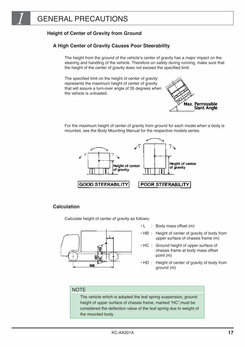
Height of Center of Gravity from Ground
A High Center of Gravity Causes Poor Steerability
The height from the ground of the vehicle’s center of gravity has a major impact on the steering and handling of the vehicle. Therefore on safety during running, make sure that the height of the center of gravity does not exceed the specified limit.
The specified limit on the height of center of gravity represents the maximum height of center of gravity that will assure a turn-over angle of 35 degrees when the vehicle is unloaded.
For the maximum height of center of gravity from ground for each model when a body is mounted, see the Body Mounting Manual for the respective models series.
Calculation
Calculate height of center of gravity as follows;• L : Body mass offset (m)• HB : Height of center of gravity of body from
upper surface of chassis frame (m)• HC : Ground height of upper surface of
chassis frame at body mass offset point (m)
• HD : Height of center of gravity of body from ground (m)
NOTE The vehicle which is adopted the leaf spring suspension, ground
height of upper surface of chassis frame, marked “HC”,must be considered the deflection value of the leaf spring due to weight of the mounted body.

GENERAL PRECAUTIONS1
KC-AA201A 18
Calculate body mass offset (L) in meters.
Calculate height of center of gravity of body from upper surface of chassis frame (HB). Calculate HB in meters according to the following example; (Model GH1JJKA truck with dry van body. )
GENERAL PRECAUTIONS1
KC-AA201A 19
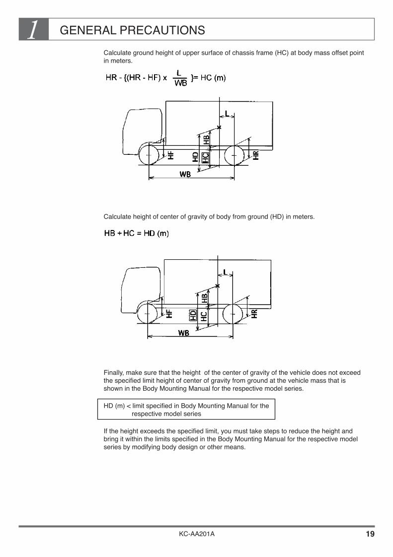
Calculate ground height of upper surface of chassis frame (HC) at body mass offset point in meters.
Calculate height of center of gravity of body from ground (HD) in meters.
Finally, make sure that the height of the center of gravity of the vehicle does not exceed the specified limit height of center of gravity from ground at the vehicle mass that is shown in the Body Mounting Manual for the respective model series.
HD (m) < limit specified in Body Mounting Manual for the respective model series
If the height exceeds the specified limit, you must take steps to reduce the height and bring it within the limits specified in the Body Mounting Manual for the respective model series by modifying body design or other means.
GENERAL PRECAUTIONS1
KC-AA201A 20
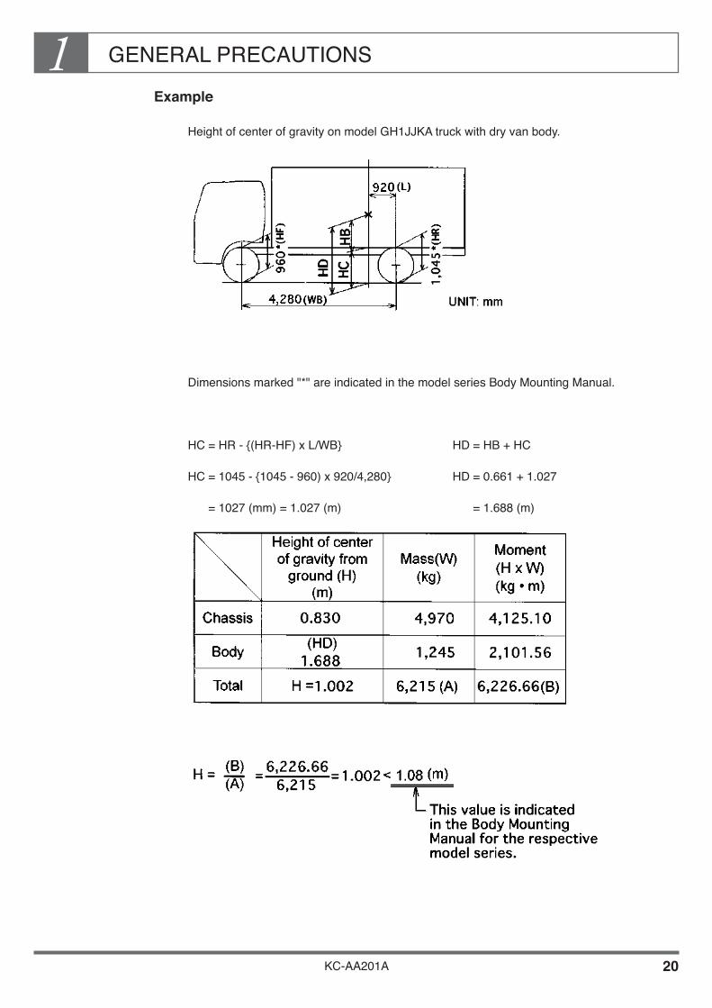
Example
Height of center of gravity on model GH1JJKA truck with dry van body.
Dimensions marked "*" are indicated in the model series Body Mounting Manual.
HC = HR - {(HR-HF) x L/WB} HD = HB + HC
HC = 1045 - {1045 - 960) x 920/4,280} HD = 0.661 + 1.027
= 1027 (mm) = 1.027 (m) = 1.688 (m)

GENERAL PRECAUTIONS1
KC-AA201A 21
Dimensions
It is the responsibility of the body and equipment manufacturer to ensure that the dimensions of the completed vehicle conform to the regulations of the country in which the vehicle is to be operated. When designing a body or equipment, in addition to observing the maximum height for the center of gravity of the completed vehicle, you should also observe the maximum rear body or equipment width specified in the body mounting manual for the respective model series. Outline of vehicle's dimensions are described as follows;
GENERAL PRECAUTIONS1
KC-AA201A 22
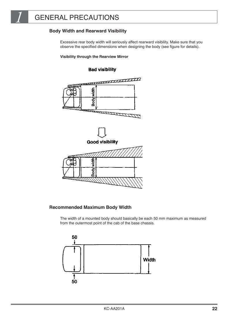
Body Width and Rearward Visibility
Excessive rear body width will seriously affect rearward visibility. Make sure that you observe the specified dimensions when designing the body (see figure for details).
Visibility through the Rearview Mirror
Recommended Maximum Body Width
The width of a mounted body should basically be each 50 mm maximum as measured from the outermost point of the cab of the base chassis.

GENERAL PRECAUTIONS1
KC-AA201A 23
Rear Over Hang
The rear overhang means the distance from the center of rear axle to the rear end of the vehicle and it is determined by wheelbase length. Please see the limitation of its extension length below.

GENERAL PRECAUTIONS1
KC-AA201A 24
4. NEVER MODIFY SAFETY PARTS
Never modify and never heat safety parts relating to the front axle, steering system or brake component, etc. Modifying or heating these parts may affect their strength and is highly dangerous. The parts of the chassis relating to the body mounting which must not be modified are as shown in the figures below.
Front Axle

GENERAL PRECAUTIONS1
KC-AA201A 25
Steering System
Brake System

GENERAL PRECAUTIONS1
KC-AA201A 26
Springs
FRONT
REAR
REAR (AIR SUSPENSION)
GENERAL PRECAUTIONS1
KC-AA201A 27
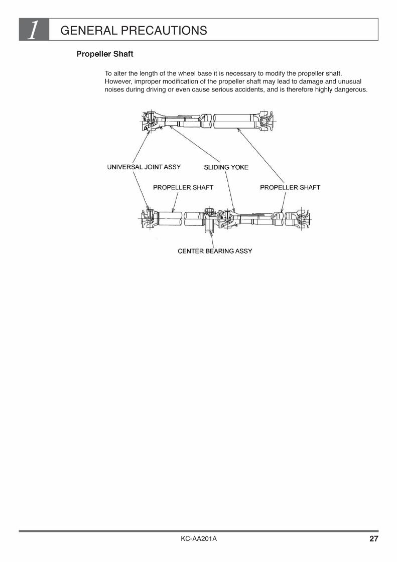
Propeller Shaft
To alter the length of the wheel base it is necessary to modify the propeller shaft. However, improper modification of the propeller shaft may lead to damage and unusual noises during driving or even cause serious accidents, and is therefore highly dangerous.

GENERAL PRECAUTIONS1
KC-AA201A 28
5. CLEARANCES
Clearance Between Chassis Parts and Body or Equipment
To prevent contact with chassis parts that vibrate or rotate during driving, be sure to allow adequate clearance between chassis parts and the body or equipment. Also be sure to allow sufficient space to allow easy filling, maintenance and repair work.
Engine, Clutch and Transmission
Clearance of Peripheral Parts with the Body
Observe the following clearances between the peripheral parts of the engine, clutch and transmission, and the mounted body or equipment.
GENERAL PRECAUTIONS1
KC-AA201A 29
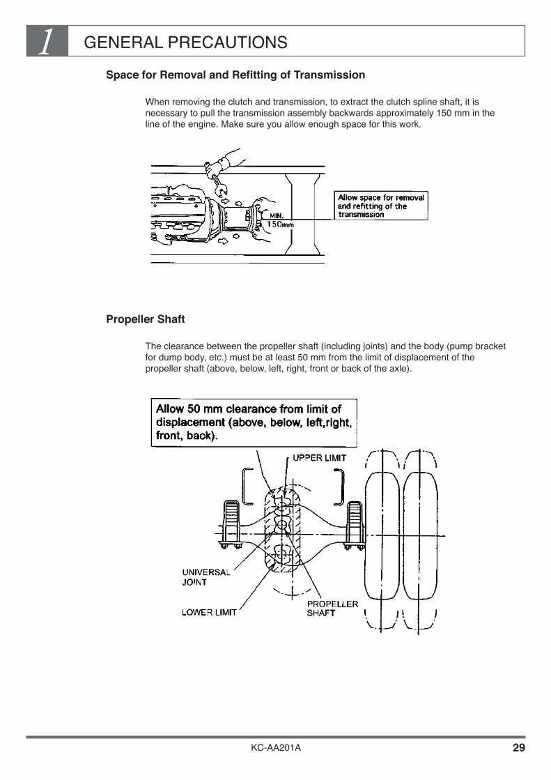
Space for Removal and Refitting of Transmission
When removing the clutch and transmission, to extract the clutch spline shaft, it is necessary to pull the transmission assembly backwards approximately 150 mm in the line of the engine. Make sure you allow enough space for this work.
Propeller Shaft
The clearance between the propeller shaft (including joints) and the body (pump bracket for dump body, etc.) must be at least 50 mm from the limit of displacement of the propeller shaft (above, below, left, right, front or back of the axle).

GENERAL PRECAUTIONS1
KC-AA201A 30
Rear Axle
Clearance when Rubber Bumper Contacting
The clearance between the rear axle (including the brake hose, torque rods and ABS harness, etc. which is located on the rear axle) and the mounted body or equipment must be at least 50 mm from the limit of displacement of the rear axle, so that the axle does not touch the mounted body or equipment nor even contact the rubber bumper.• For details of range of axle movement, see the Body Mounting Manual for the
respective model series.
Single rear axle
Tandem rear axle
*
*
**
*
*
*
Upper limit
Front
Torque rod Torque rod
Air hose for interaxle differential
When contacting metal When contacting metal
* ** *
Rear rear axleRear front axle
Rea
r ax
le d
atum
line
*
Service brake hose
GENERAL PRECAUTIONS1
KC-AA201A 31
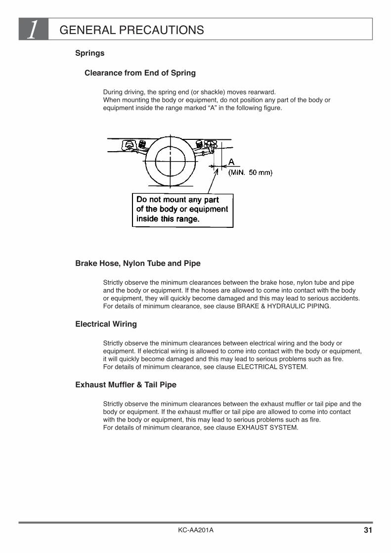
Springs
Clearance from End of Spring
During driving, the spring end (or shackle) moves rearward. When mounting the body or equipment, do not position any part of the body or equipment inside the range marked “A” in the following figure.
Brake Hose, Nylon Tube and Pipe
Strictly observe the minimum clearances between the brake hose, nylon tube and pipe and the body or equipment. If the hoses are allowed to come into contact with the body or equipment, they will quickly become damaged and this may lead to serious accidents. For details of minimum clearance, see clause BRAKE & HYDRAULIC PIPING.
Electrical Wiring
Strictly observe the minimum clearances between electrical wiring and the body or equipment. If electrical wiring is allowed to come into contact with the body or equipment, it will quickly become damaged and this may lead to serious problems such as fire. For details of minimum clearance, see clause ELECTRICAL SYSTEM.
Exhaust Muffler & Tail Pipe
Strictly observe the minimum clearances between the exhaust muffler or tail pipe and the body or equipment. If the exhaust muffler or tail pipe are allowed to come into contact with the body or equipment, this may lead to serious problems such as fire. For details of minimum clearance, see clause EXHAUST SYSTEM.
GENERAL PRECAUTIONS1
KC-AA201A 32
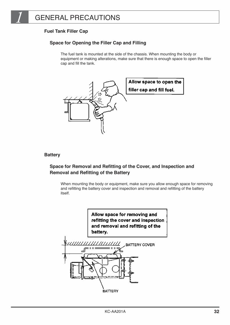
Fuel Tank Filler Cap
Space for Opening the Filler Cap and Filling
The fuel tank is mounted at the side of the chassis. When mounting the body or equipment or making alterations, make sure that there is enough space to open the filler cap and fill the tank.
Battery
Space for Removal and Refitting of the Cover, and Inspection and Removal and Refitting of the Battery
When mounting the body or equipment, make sure you allow enough space for removing and refitting the battery cover and inspection and removal and refitting of the battery itself.

GENERAL PRECAUTIONS1
KC-AA201A 33
Brake Booster
Space for inspection, topping up, and air bleeding
In the air-over type brakes used in medium and large-sized vehicles, the brake booster has a fluid reservoir. When mounting the body or equipment, make sure you allow space for inspecting and topping up the brake fluid, and bleeding air from the brake booster.
Air Drier
Space for inspection and replacement work
The air drier (in full-air or air-over type brakes) contains a desiccant, which must be inspected and replaced at regular intervals. This job involves removing and remounting the air drier. Make sure you allow space for removing and remounting the air drier.
GENERAL PRECAUTIONS1
KC-AA201A 34
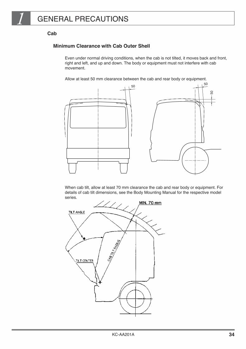
Cab
Minimum Clearance with Cab Outer Shell
Even under normal driving conditions, when the cab is not tilted, it moves back and front, right and left, and up and down. The body or equipment must not interfere with cab movement.
Allow at least 50 mm clearance between the cab and rear body or equipment.
When cab tilt, allow at least 70 mm clearance the cab and rear body or equipment. For details of cab tilt dimensions, see the Body Mounting Manual for the respective model series.
50
50
50

GENERAL PRECAUTIONS1
KC-AA201A 35
Minimum Clearance with Cab Rear End
The rear part of the cab contains the cab lock mechanism and the tilt mechanism, as well as the engine cylinder block or other various equipment. When mounting the body or equipment, allow at least the minimum clearance between the rear end of the cab and the front end of the rear body or equipment, to avoid obstructing the operation and maintenance of these mechanisms or various equipment.
For details of cab back dimensions, see the Body Mounting Manual for the respective model series.

GENERAL PRECAUTIONS1
KC-AA201A 36
Minimum Clearance with Engine Air Intake Port
The engine air intake port is located at the rear of the cab. Be sure to maintain the proper clearance so as not to obstruct the air intake. The drawings below apply to the Heavy-duty truck series only. For details of relevant model, see the Body Mounting Manual for the respective model series.
*
*
FRONT
*
FR
ON
T A
XLE
DA
TU
M L
INE
CH
AS
SIS
CE
NT
ER
LIN
E
UPPER SURFACE OFCAHSSIS FRAME
AIR INTAKE PORTUNIT : mm
50
FR
ON
T E
ND
OF
SU
PE
RS
TR
UC
TU
RE
(C
AN
VA
S, E
TC
.)
RIGHT
BACK OF CAB RIGHT SIDE OF CAB
GENERAL PRECAUTIONS1
KC-AA201A 37
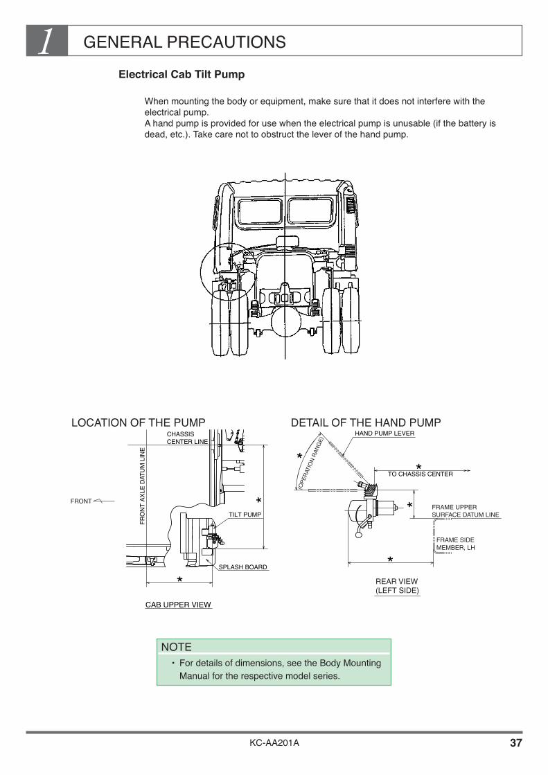
Electrical Cab Tilt Pump
When mounting the body or equipment, make sure that it does not interfere with the electrical pump. A hand pump is provided for use when the electrical pump is unusable (if the battery is dead, etc.). Take care not to obstruct the lever of the hand pump.
LOCATION OF THE PUMP DETAIL OF THE HAND PUMP
NOTE• For details of dimensions, see the Body Mounting
Manual for the respective model series.
*
*
TO CHASSIS CENTER
*(O
PE
RAT
ION
RA
NG
E)
FRAME UPPERSURFACE DATUM LINE
FRAME SIDEMEMBER, LH
REAR VIEW(LEFT SIDE)
HAND PUMP LEVER
*
*
*
FRONT
FR
ON
T A
XLE
DAT
UM
LIN
E
CHASSISCENTER LINE
TILT PUMP
SPLASH BOARD
CAB UPPER VIEW
GENERAL PRECAUTIONS1
KC-AA201A 38
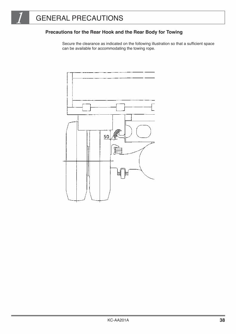
Precautions for the Rear Hook and the Rear Body for Towing
Secure the clearance as indicated on the following illustration so that a sufficient space can be available for accommodating the towing rope.
GENERAL PRECAUTIONS1
KC-AA201A 39
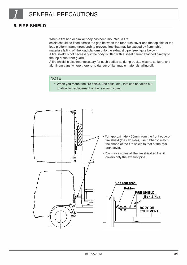
6. FIRE SHIELD
When a flat bed or similar body has been mounted, a fire shield should be fitted across the gap between the rear arch cover and the top side of the load platform frame (front end) to prevent fires that may be caused by flammable materials falling off the load platform onto the exhaust pipe (see figure below). A fire shield is not necessary if the body is fitted with a sheet carrier attached directly to the top of the front guard. A fire shield is also not necessary for such bodies as dump trucks, mixers, tankers, and aluminum vans, where there is no danger of flammable materials falling off.
NOTE• When you mount the fire shield, use bolts, etc., that can be taken out
to allow for replacement of the rear arch cover.
• For approximately 50mm from the front edge of fire shield (the cab side), use rubber to match the shape of the fire shield to that of the rear arch cover.
• You may also install the fire shield so that it covers only the exhaust pipe.

GENERAL PRECAUTIONS1
KC-AA201A 40
7. ACCESSIBILITY FOR MAINTENANCE
When mounting a body or equipment, make sure you allow room for inspection and lubrication of chassis components.
Chassis Parts Requiring Inspection and Lubrication.

GENERAL PRECAUTIONS1
KC-AA201A 41
8. APPROACH AND DEPARTURE ANGLES
If you intend to mount parts of the body at a relatively low position in the front or rear overhang, make the approach angle and departure angle equal to or greater than the chassis standard angle. If, for unavoidable reasons, you must make these angles smaller than the chassis standard, make sure to allow for operating conditions when deciding the ground height of mounted parts of the body or equipment.

GENERAL PRECAUTIONS1
KC-AA201A 42
9. EXTERNAL NOISE CONTROL PARTS
Precautions for Handling Parts
External noise control parts [sound-insulating materials (covers, rubber), sound-absorbing materials, a muffler and tail pipe] are fitted to meet regulations in the country in which the vehicle is to be used. When carrying out modifications, observe the following precautions:• The specifications of each parts are determined in accordance with external noise
control regulations. Do not remove or alter the parts in any way.• If you must temporarily detach any external noise control parts, handle it carefully in
order to avoid deforming or damaging it, and make sure you refit the parts in its original position when you have finished the body mounting or alteration work. If any external noise reduction parts is distorted or damaged, replace it with a new genuine part. Never use a repaired parts.
• For details of noise control parts, see the Body Mounting Manual for the respective model series.

GENERAL PRECAUTIONS1
KC-AA201A 43
10. AVOIDING DAMAGE TO CHASSIS
When mounting the body or equipment, be careful not to damage the chassis or interfere with its functions. For example, do not stand on brake component (ex. ABS modulator, LSV), brake pipes and hoses, fuel pipes and hoses, battery and wiring harness, T/M control rods or cables, and etc.
11. LEAF ADDITIONS
Leaves should not be added to leaf springs beyond the number of leaves which have been prepared as an option as this may lead to snags in the steering system at the front and unusual propeller shaft noise.
12. SHIPMENT
After mounting the body or equipment, make sure that there is no body vibration, noise or other abnormalities before shipping the vehicle. (Perform a thorough shipping inspection.)
Brake, steering and suspension systems are all important safety components. If any of these components have had to be temporarily removed to allow for body mounting or alterations, make sure that they are refitted exactly as before and verify their operation before shipping the vehicle. (Be sure to perform a thorough shipping inspection.)
13. TOWING VEHICLES
If you must tow a vehicle, be sure to remove the propeller shaft before towing. (This is not necessary when moving vehicles inside a factory during body mounting or alterations.)
14. COMPLYING WITH LAWS AND REGULATIONS
The completed vehicle with body or equipment fitted must comply with the vehicle laws and regulations of the country in which it is used and tolerance limits for axle capacity, weight distribution on front axle and height of the center of gravity must not be exceeded.

GENERAL PRECAUTIONS1
KC-AA201A 44
15. PREPARATION OF OPERATION MANUAL AND/OR MAINTENANCE & INSPECTION
Manual and Their Installation on Vehicles
In the event that the body mounting or alterations cause a change in the procedure for operation, maintenance, inspection or adjustment of the standard vehicle, an operation manual should be prepared and installed on the vehicle.
An operation manual and/or a maintenance & inspection manual specifying the procedure for the operation, maintenance, inspection and adjustment including inspection intervals of the particular mounting or alterations should be prepared and installed in the vehicle.
16. ESTABLISHING AFTER-SALE SERVICE SYSTEM
Take adequate care to establish an after-sale service system for the parts mounted or altered.
GENERAL PRECAUTIONS1
KC-AA201A 45
17. TRACTOR VEHICLE
Introduction
In recent years, HINO tractors are often delivered without coupling device to provide flexibility for connection in the country of destination. You will find below important points to take into account when installing a 5th wheel.
CONTENTS
Mass and dimension Kinds and features of couplers Trailer brake system Trailer electrical wiring Precaution to take when calculating a load
on the 5th wheel and a coupler offset Front fitting radius and rear fitting radius Tractor posture after connecting the trailer Prevention of interference between the tractor
and the trailer How to install the coupler (for reference)

GENERAL PRECAUTIONS1
KC-AA201A 46
Mass and Dimensions
Formulae for Calculation ( Tractor Vehicle) When Calculating
gross combination mass
coupler offset,
body mass and
load center (coupler offset), use the formulae described in this section.
Gross Combination Mass (GCM)
What is Gross Combination Mass (GCM) ;

GENERAL PRECAUTIONS1
KC-AA201A 47
Basic Formulae for Mass Distribution (Tractor Vehicle)
The distribution of mass for tractor on each axles is calculated as follows ;
W4 (5th wheel load) =
W1c (Trailer rear axle) = (W1 + W2 + W3) - W4
W2c (Tractor front axle) =
W3c (Tractor rear axle) = (W4 + W5) - W2c
NOTE• Example of basic calculating for one unit load and multiple units load
mass distribution on front and rear axles is described in this clause page 12.
(W1 x L1) + (W2 x L2) - (W3 x L3)L4
(W4 x L6) + (W5 x L5)WB

GENERAL PRECAUTIONS1
KC-AA201A 48
Calculation of Gross Combination Mass
The details of each factor used in calculating GCM are as follows;
CHASSIS MASS (TRACTOR)
Wfc and Wrc are given “1 Vehicle Summary ----------Chassis Specification” in the Body Mounting Manual for the respective model series.
TRAILER MASS
Calculate Wft and Wrt of Trailer Mass using the basic formulae for mass distribution.
ConstructionGuard frameLanding gear
Tool boxSide gates
Floor const.Trailer frameTrailer axle (front)
Trailer axle (rear)Tail gate
Mass (W)
W1
W2
W3
W4
W5
W6
W7
W8
W9
L1
L2
L3
L4
L5
L6
L7
L8
L9
Length (L)
[Example for Cargo Trailer ]
GENERAL PRECAUTIONS1
KC-AA201A 49
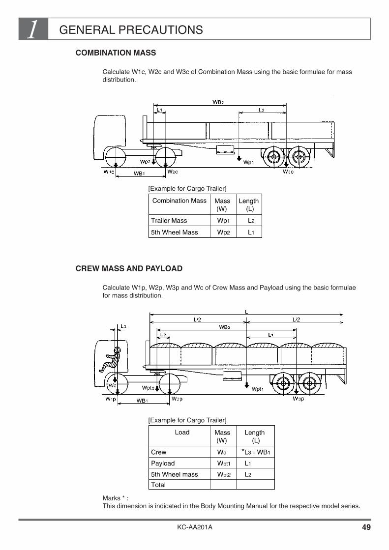
COMBINATION MASS
Calculate W1c, W2c and W3c of Combination Mass using the basic formulae for mass distribution.
CREW MASS AND PAYLOAD
Calculate W1p, W2p, W3p and Wc of Crew Mass and Payload using the basic formulae for mass distribution.
Marks * : This dimension is indicated in the Body Mounting Manual for the respective model series.
Combination Mass
Trailer Mass
5th Wheel Mass
Mass (W)
Wp1
Wp2
L2
L1
Length (L)
Load
Crew
Payload
5th Wheel mass
Total
Mass (W)
Wc
Wpt1
Wpt2
*L3 + WB1
L1
L2
Length (L)
[Example for Cargo Trailer]
[Example for Cargo Trailer]

GENERAL PRECAUTIONS1
KC-AA201A 50
Load Center (5th wheel offset)
Condition for calculation of load center (LC)
Calculate the fifth wheel offset that will satisfy the following conditions.
For detailed explanation on each item, refer to the items 2) to 8) on the following page.
Wcr
Wp
H
GCM
GVM
Front axle Mass
Rear axle Mass
Tire capa.
Wcf / GVM ≥ 30%
Wcr / GCM ≥ 25%
Less than 5th wheel.
H = H1 - H2 = 100 ~ 150mm
Less than GCMR
Less than GVMR
Less than Front axle capa.
Less than Rear axle capa.
Less than tire capa.
Wcf / GVM ≥ 20%Wcf
4 x 2 Tractor 6 x 4 Tractor
Wcr / GCM ≥ 25%
Less than 5th wheel.
H = H1 - H2 = 100 ~ 150mm
Less than GCMR
Less than GVMR
Less than Front axle capa.
Less than Rear axle capa.
Less than tire capa.
A - C ≥ 80mm
D - B ≥ 100 mm
A - C ≥ 80mmFront FittingRadiusRear FittingRadius D - B ≥ 100 mm

GENERAL PRECAUTIONS1
KC-AA201A 51
Example of Calculation of Mass Distribution
Calculating mass distribution for a Model SH2FDSA with cargo trailer.
Calculation of Gross Combination Mass, Gross Vehicle Mass, Gross Axle Mass and 5th wheel mass.
Mass distribution on front axle of tractor
x 100 = x 100 = 35.4 > 30%
Mass distribution on rear axle of tractor
x 100 = x 100 = 30.7 > 25%
TRACTOR MASS 6555
TOTAL
520011755
20000195
45500
TRAILER MASSV. M. COMBINED
PAYLOADCREW MASS
GCMR, GVMRAXLE AND 5TH WHEEL CAPA.
TIRE SIZE TIRE CAPA.
4130FRONT
TRACTOR TRAILER
160
900210
6000
2425REAR
111035354290
6310-15
31950GCM, GVM 5400
6555TOTAL
1270
7210195
19000
15230 9830
13000
5TH WHEEL
1270
7210
8480
9600
REAR
Unit : kg
3930
12790
16720
9.00-20-14PR11.00-20-14PR184006000 10900
Fr
GVM
5400
15230
Rr
GCM
9830
31950
GENERAL PRECAUTIONS1
KC-AA201A 52
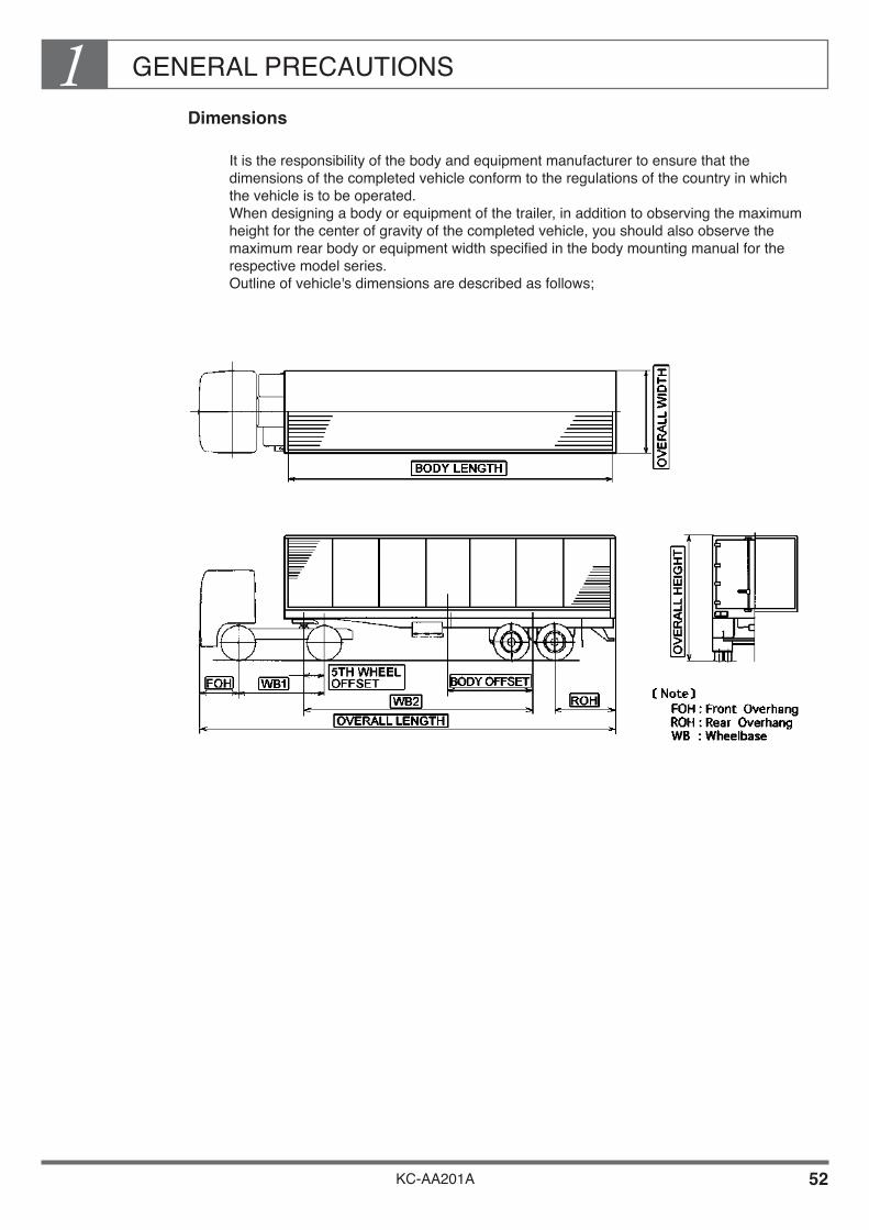
Dimensions
It is the responsibility of the body and equipment manufacturer to ensure that the dimensions of the completed vehicle conform to the regulations of the country in which the vehicle is to be operated. When designing a body or equipment of the trailer, in addition to observing the maximum height for the center of gravity of the completed vehicle, you should also observe the maximum rear body or equipment width specified in the body mounting manual for the respective model series. Outline of vehicle's dimensions are described as follows;

GENERAL PRECAUTIONS1
KC-AA201A 53
Body Width and Rearward Visibility
Excessive rear body width will seriously affect rearward visibility. Make sure that you observe the specified dimensions when designing the body (see figure for details).
Visibility through the Rearview Mirror
Recommended Maximum Body Width
The width of a mounted body should basically be each 50 mm maximum as measured from the outermost point of the cab of the base chassis.

GENERAL PRECAUTIONS1
KC-AA201A 54
Kinds and Features of Couplers (5th Wheel)
Couplers can be roughly classified into 2 kinds. Select your coupler taking into account the use of vehicle as well as its features as mentioned in the following table.
SINGLE AXLE TYPE COUPLER
DOUBLE AXLE TYPE COUPLER
MOUNTING PLATE
PICHING SHAFT COUPLER
KIND OF COUPLER
Single axle type
DRIVE SYSTEM MAINLY USED ON TRACTOR
4 x 2
PURPOSE FOR USE AND FEATURES
Used on a high-speed type tractor. It enhances stability in high-speed running by limiting rolling.Slight rolling appearing when driving can be absorbed by tractor springs and torsion of tractor frames. Mainly used for well paved road and high-speed running.
Double axle type 6 x 4 Mainly used on tractors transporting heavy cargo and towing low-bed semi-trailer with low center of gravity. Mutual torsion appearing on tractor and semi-trailer in all directions is absorbed by the coupler. Suitable for low speed run and towing heavy goods.
MOUNTING PLATE
PICHING SHAFT COUPLERROLLING SHAFT

GENERAL PRECAUTIONS1
KC-AA201A 55
Trailer Brake System
The trailer brake system can be actuated by operating the foot brake and hand brake valves that are provided at the inside of the tractor cab. The trailer brake system is connected by a jumper hose and an air-coupling. The air-coupling equipped on the HINO vehicle complies with SAE standard and color distinction is made to clarify the purpose for use; Blue being for Service purpose while Red being for an Emergency purpose. The actual form is as shown below.
GENERAL PRECAUTIONS1
KC-AA201A 56
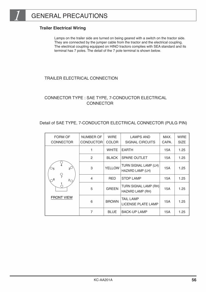
Trailer Electrical Wiring
Lamps on the trailer side are turned on being geared with a switch on the tractor side. They are connected by the jumper cable from the tractor and the electrical coupling. The electrical coupling equipped on HINO tractors complies with SEA standard and its terminal has 7 poles. The detail of the 7 pole terminal is shown below.
TRAILER ELECTRICAL CONNECTION
CONNECTOR TYPE : SAE TYPE, 7-CONDUCTOR ELECTRICAL CONNECTOR
Detail of SAE TYPE, 7-CONDUCTOR ELECTRICAL CONNECTOR (PULG PIN)
FORM OF
CONNECTOR
NUMBER OF
CONDUCTOR
WIRE
COLOR
LAMPS AND
SIGNAL CIRCUITS
1 WHITE EARTH
2 BLACK SPARE OUTLET
3 YELLOWTURN SIGNAL LAMP (LH)
HAZARD LAMP (LH)
4 RED STOP LAMP
5 GREENTURN SIGNAL LAMP (RH)
HAZARD LAMP (RH)
6 BROWNTAIL LAMP
LICENSE PLATE LAMP
7 BLUE BACK-UP LAMP
MAX.
CAPA.
15A
15A
15A
15A
15A
15A
15A
WIRE
SIZE
1.25
1.25
1.25
1.25
1.25
1.25
1.25
435
6 21
7
FRONT VIEW

GENERAL PRECAUTIONS1
KC-AA201A 57
Precaution to Take When Calculating the Load on the 5th Wheel and the Coupler (5th wheel) Offset
In order to satisfy the load imposed on the axle, weight distribution, vibrations and riding comfort, it is necessary to decide 5th wheel load and coupler (5th wheel) offset that are compatible with the vehicle. When deciding the 5th wheel load and the coupler (5th wheel) offset in preliminary examination, observe at least the following requirements for the sake of vehicle assurance.• GCMR when a trailer under loaded condition is connected.
(less than the value set by HINO.)• GVMR of tractor when a trailer under loaded condition is connected.
(less than the value set by HINO.)• Axle capacity under the conditions 1) and 2) above.
(less than the value set by HINO.)• Tire capacity under the conditions 1) and 2) above.
(less than the value set by tire manufacturer.)• 5th wheel load when the trailer is connected under loaded condition. (less than the
value set by coupler manufacturer.) Also, the following recommended values should be observed in order to ensure driving
stability and riding comfort of the vehicle.• Front axle load / GVM = 4 x 2 tractor : More than 30%
6 x 4 tractor : More than 20% (when a tractor under loaded condition is connected.)
• Rear axle load / GCM = More than 25% (when a tractor under loaded condition is connected.)

GENERAL PRECAUTIONS1
KC-AA201A 58
Front Fitting Radius and Rear Fitting Radius
“A” in the following illustration is called as “Front fitting radius” while “B” is named as “Rear fitting radius”.
They are provided for preventing the interference between the tractor and the trailer when they are connected, particularly at the time of turning. In the case of tractor which is delivered without a coupler, position of coupler base and of coupler mounting, etc. are not decided. Therefore, calculate the front fitting radius and rear fitting radius according to the calculating method indicated on the following table.
Minimum clearance between tractor and trailer
TRACTOR TRAILER
A
B
CFRONT FITTING RADIUS
REAR FITTING RADIUS D
CLEARANCE
A - C ≥ 80mm
D - B ≥ 100 mm
GENERAL PRECAUTIONS1
KC-AA201A 59
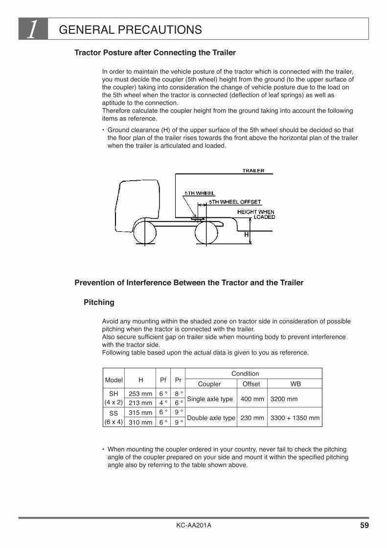
Tractor Posture after Connecting the Trailer
In order to maintain the vehicle posture of the tractor which is connected with the trailer, you must decide the coupler (5th wheel) height from the ground (to the upper surface of the coupler) taking into consideration the change of vehicle posture due to the load on the 5th wheel when the tractor is connected (deflection of leaf springs) as well as aptitude to the connection. Therefore calculate the coupler height from the ground taking into account the following items as reference.• Ground clearance (H) of the upper surface of the 5th wheel should be decided so that
the floor plan of the trailer rises towards the front above the horizontal plan of the trailer when the trailer is articulated and loaded.
Prevention of Interference Between the Tractor and the Trailer
Pitching
Avoid any mounting within the shaded zone on tractor side in consideration of possible pitching when the tractor is connected with the trailer. Also secure sufficient gap on trailer side when mounting body to prevent interference with the tractor side. Following table based upon the actual data is given to you as reference.
• When mounting the coupler ordered in your country, never fail to check the pitching angle of the coupler prepared on your side and mount it within the specified pitching angle also by referring to the table shown above.
Model
(4 x 2)
(6 x 4)
SH
SS
H
253 mm213 mm315 mm310 mm
Pf
6 °4 °6 °6 °
Pr
8 °6 °9 °9 °
ConditionCoupler Offset
Single axle type
Double axle type
WB
400 mm
230 mm
3200 mm
3300 + 1350 mm
GENERAL PRECAUTIONS1
KC-AA201A 60
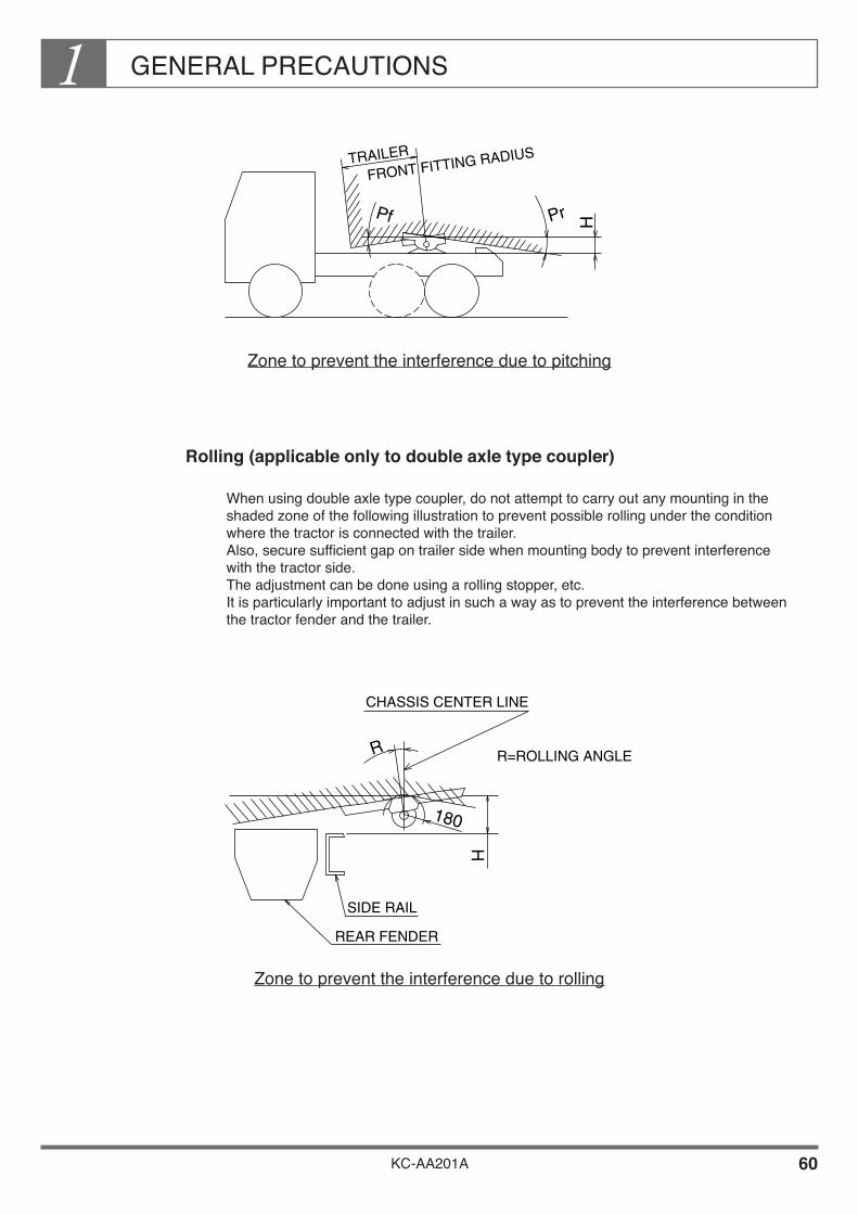
Zone to prevent the interference due to pitching
Rolling (applicable only to double axle type coupler)
When using double axle type coupler, do not attempt to carry out any mounting in the shaded zone of the following illustration to prevent possible rolling under the condition where the tractor is connected with the trailer. Also, secure sufficient gap on trailer side when mounting body to prevent interference with the tractor side. The adjustment can be done using a rolling stopper, etc. It is particularly important to adjust in such a way as to prevent the interference between the tractor fender and the trailer.
Zone to prevent the interference due to rolling
FRONT FITTING RADIUSTRAILER
Pf Pr H
SIDE RAIL
REAR FENDER
CHASSIS CENTER LINE
R=ROLLING ANGLE
H
180
R

GENERAL PRECAUTIONS1
KC-AA201A 61
How to Install the Coupler (For Reference)
Check the capacity of the coupler that you will prepare and mount on your side. When deciding 5th wheel load, you should satisfy the setting conditions mentioned in the item (1) to (5) below.
When mounting a 5th wheel on your tractor, never fail to place a coupler base and mounting plate on the chassis and then to mount the 5th wheel. The coupler base and mounting plate recommended by HINO for one of example is shown at P.64 & 65.
When using a mounting plate supplied by the 5th wheel manufacturer, fit it on the coupler base according to the recommendation given by the 5th wheel manufacturer.
When making the coupler base and mounting plate, make it by referring to the coupler base and Mounting Plate recommended by HINO for one of example shown at P.64 & 65 and by observing the following instructions.• Fix the coupler base at more than 7 positions on one side using fixing bolts whose neck
diameter is more than 16mm.• Fix the mounting plate at more than 6 positions on one side using fixing bolts whose
neck diameter is more than 16mm.• Use the material of bolt : JIS G 4052 Steel material for structure equivalent to - High
tensile strengthen steel : SMnC443H, SCr435H, SCM435.
• Before fitting the coupler base and mounting plate, make escape or escape holes in order to escape from the bolts on web surface and rivet heads on the upper surface of the chassis frame.
Mount lower support bracket for 5th wheel at the back of the 5th wheel. (Refer to P.66)
Mount slide rail for 5th wheel at the rear end of the chassis frame. (Refer to P.67)

GENERAL PRECAUTIONS1
KC-AA201A 62
5TH WHEEL MOUNTING METHOD (EXAMPLE)Unit : mm

GENERAL PRECAUTIONS1
KC-AA201A 63
COUPLER BASE MOUNTING METHOD (EXAMPLE)Unit : mm
COUPLER BASE CROSS SECTION
KC-AA201A 64
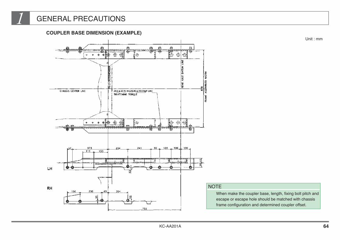
GENERAL PRECAUTIONS1COUPLER BASE DIMENSION (EXAMPLE)
Unit : mm
NOTE When make the coupler base, length, fixing bolt pitch and
escape or escape hole should be matched with chassis frame configuration and determined coupler offset.

KC-AA201A 65
GENERAL PRECAUTIONS1RECOMMENDED 5TH WHEEL MOUNTING PLATE DIMENSION (EXAMPLE)
Unit : mm

KC-AA201A 66
GENERAL PRECAUTIONS1LOWER SUPPORT BRACKET FOR 5TH WHEEL (EXAMPLE)
Unit : mm

GENERAL PRECAUTIONS1
KC-AA201A 67
SLIDE RAIL FOR 5TH WHEEL (EXAMPLE)Unit : mm

KC-AA201A
Chapter 2CHASSIS FRAME
1. FRAME MATERIALS ••••••••••••••••••••••••••••••••••••••••••• 2 2. DRILLING AND WELDING •••••••••••••••••••••••••••••••••••• 3 3. PROCESSING FOR DRILLING AND
WELDING WORK •••••••••••••••••••••••••••••••••••••••••••• 6 4. SIDE MEMBER REINFORCEMENT •••••••••••••••••••••••• 14 5. OTHER PRECAUTIONS FOR DRILLING
AND ELECTRICAL WELDING •••••••••••••••••••••••••••• 21 6. EXTENSION OF SIDE MEMBER REAR END •••••••••••• 24 7. MOUNTING THE REAR HOOK •••••••••••••••••••••••••••••• 31 8. MOUNTING THE REAR PINTLE HOOK ••••••••••••••••••• 33 9. MOUNTING A PART ON THE SIDE MEMBER ••••••••••• 35

CHASSIS FRAME2
KC-AA201A 1
In normal operation, the chassis frame and body frame provide sufficient strength for the mounting of a standard cargo or van body.
However, if equipment such as a small crane at the back of the cab or a mixer are fitted, the chassis frame will be subject to concentrated loads and the chassis frame alone will not give sufficient strength. To help spread the load, you must strengthen the body structure (especially strengthening members corresponding to the sub frame=longitudinal main floor member of body or equipment) or the chassis frame itself, using L-shaped stiffeners to achieve sufficient strength for the mounting of the rear body or equipment.
The chassis frame is the “backbone” of the vehicle. This section describes precautions to be taken when drilling holes or performing welding work in fitting a normal body or equipment, or when making modifications such as fitting stiffeners, etc.
CHASSIS FRAME2
KC-AA201A 2
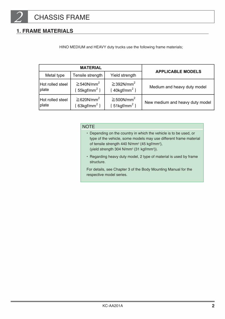
1. FRAME MATERIALS
HINO MEDIUM and HEAVY duty trucks use the following frame materials;
NOTE• Depending on the country in which the vehicle is to be used, or
type of the vehicle, some models may use different frame material of tensile strength 440 N/mm2 {45 kgf/mm2}, (yield strength 304 N/mm2 {31 kgf/mm2}).
• Regarding heavy duty model, 2 type of material is used by frame structure.
For details, see Chapter 3 of the Body Mounting Manual for the respective model series.
Metal type Tensile strength Yield strength
Hot rolled steelplate
≧540N/mm2
{ 55kgf/mm2 }≧392N/mm2
{ 40kgf/mm2 }Medium and heavy duty model
Hot rolled steelplate
≧620N/mm2
{ 63kgf/mm2 }≧500N/mm2
{ 51kgf/mm2 }New medium and heavy duty model
MATERIALAPPLICABLE MODELS

CHASSIS FRAME2
KC-AA201A 3
2. DRILLING AND WELDING
Summary of Drilling and Welding
Be sure to observe the following instructions when drilling holes and welding on the frame. Especially in the case where a high tensile strength steel (tensile strength: 540N/mm2{55kgf/mm2}) is used as material not only for side members but also for a part of crossmembers and gussets, sharp fall strength occurs due to notches, welding method, thermal effect, etc. in comparison with the case where an ordinary frame steel (tensile strength: 440N/mm2{45kgf/mm2}) is used. For such reasons, inadequate drilling and welding sometimes result in fracture of the frame. Therefore, avoid drilling hole and welding on the frame as much as possible.
In case of new series of heavy duty models, high tensile strength steel (tensile strength : 620N/mm2{ 63kgf/mm2 }) is used for side members, and sharp fall strength occurs due to same case mentioned above condition. Therefore, avoid drilling hole and welding on the frame. Instead of that, we provide holes in new series of heavy duty models. (For details, see chapter 2 of the Body Mounting Manual for the respective model series.)
Be sure to observe the following instructions for drilling , welding and handling of the frame.

CHASSIS FRAME2
KC-AA201A 4
General informations
[Drilling]• Use an ordinary drill and never use heat such as a gas torch.• Always chamfer after drilling.
[Welding]Tighten with bolts or rivets instead of welding. If this cannot be done, the following precautions should be taken.• Take off the chassis-mounted parts (brake lines, fuel lines and electrical circuitry etc.)
to protect them from sparks before performing welding.• Clean the welded area before welding and make certain that the welding rod is the one
best suited for the materials to be welded.• Keep welding speed and rod position in the optimum condition with the welding current
at the optimum amperage in order to avoid defective welding work such as incomplete welding, undercut, slug fusing blowholes, cracks, pitting, etc.
• Always connect the ground wire close to the side rail area to be welded and when welding, must be remove the battery terminals.
• To reduce stress caused by welding, minimize the length of the welded area as well as the amount of welding application.
• Avoid close-spacing of weld joints as much as possible.• Avoid welding edges and bends because high welding skill is required.
CHASSIS FRAME2
KC-AA201A 5
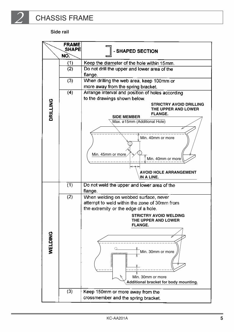
Side rail
Min. 40mm or more
Min. 45mm or moreMin. 40mm or more
AVOID HOLE ARRANGEMENT IN A LINE.
SIDE MEMBER Max. ø15mm (Additional Hole)
STRICTRY AVOID DRILLINGTHE UPPER AND LOWER FLANGE.
Min. 30mm or more
Min. 30mm or moreAdditional bracket for body mounting.
STRICTRY AVOID WELDINGTHE UPPER AND LOWER FLANGE.

CHASSIS FRAME2
KC-AA201A 6
3. PROCESSING FOR DRILLING AND WELDING WORK
Use bolts or rivets for fastening and avoid welding as far as practicable.
Drilling
Don’t use gas or heat to from a hole but always use a drilling machine.• After drilling, always finish with chamfering.
Drilling side member
Don’t drill in the upper and lower surface of the flange.
Make sure that the hole drilled is 15mm maximum.
CHASSIS FRAME2
KC-AA201A 7
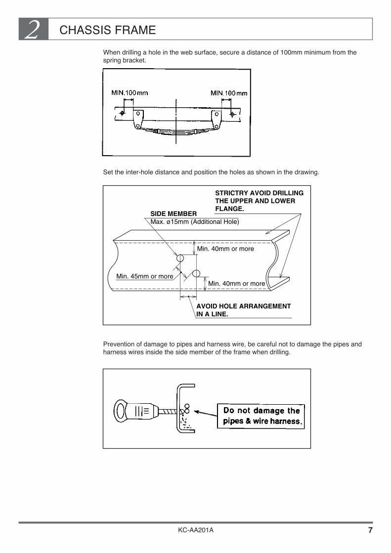
When drilling a hole in the web surface, secure a distance of 100mm minimum from the spring bracket.
Set the inter-hole distance and position the holes as shown in the drawing.
Prevention of damage to pipes and harness wire, be careful not to damage the pipes and harness wires inside the side member of the frame when drilling.
Min. 40mm or more
Min. 45mm or moreMin. 40mm or more
AVOID HOLE ARRANGEMENT IN A LINE.
SIDE MEMBER Max. ø15mm (Additional Hole)
STRICTRY AVOID DRILLINGTHE UPPER AND LOWER FLANGE.

CHASSIS FRAME2
KC-AA201A 8
Drilling cross member
Don’t drill a hole in or make modifications otherwise to the alligator-shaped crossmember.

CHASSIS FRAME2
KC-AA201A 9
Welding
Preparations
Before carrying out the welding work, remove the brake-related parts, fuel-related parts and wirings as far as possible in order for the chassis parts not to be exposed to welding sparks.
To prevent damage to ancillary components from sparks during welding, cover the engine, meters, steering wheel, houses, brake pipes, harness wires and tires, etc. with fire-resistant covers.
Clean the welding zone sufficiently beforehand.
Check to see that the welding rod is suitable for the material of the welding zone.• Make sure that the tensile strength and the yield point of the welding rod are identical to
those of the base material.
WELDING RODS
Use special welding rods for high tensile steel in places where the weld must have the same strength as the base metal.
NOTE JIS AND ISO STANDARDS ARE SHOWN BELOW.
• JIS Z3211 : 2008 • ISO 2560 : 2009(E)
BASE METAL (FRAME) WELDING ROD
Hot rolled steel plate : tensile strength 440N/m㎡
{ 45kgf/m㎡ }
Same tensile strength as base metal (JIS E4316 or ISO E4316)
Hot rolled steel plate : tensile strength 540N/m㎡
{ 55kgf/m㎡ }
Same tensile strength as base metal (JIS E4919 or ISO E4919)
Hot rolled steel plate : tensile strength 620N/m㎡
{ 63kgf/m㎡ }
Same tensile strength as base metal (JIS E5516 or ISO E5516)

CHASSIS FRAME2
KC-AA201A 10
During the welding work, always be sure to ground the parts involved at a point in the vicinity of the weld zone of the side member. Welding processings to avoid damaging of chassis electrical parts:• Turn the starter switch off.• Disconnect the negative ground of the battery.• Disconnect all electronic instruments (e.g. ABS, Engine control computer).• Earth all welding equipment properly, near the area to be welded.
Operation
Maintain a constant welding rate with an optimum current in order to avoid fusion irregularities.

CHASSIS FRAME2
KC-AA201A 11
See to it that there is no welding defects such as incomplete welding, undercut, slug inclusion, blowhole or crackings.
WELDING BEAD SHAPE
Make sure that the shape of the welding beads corresponds to the shape illustrated below
1. Undercut 2. Concave welding 3. This area should be smooth and free from undercuts.
In order to reduce the stress caused by welding, the welding length should be as short as possible and the welding volume should be kept at a required minimum to secure the strength.
Avoid concentration or proximity of welding joints as far as possible. Don’t carry out the welding work on edges or bent portions as it demands a considerable welding skill.
CHASSIS FRAME2
KC-AA201A 12
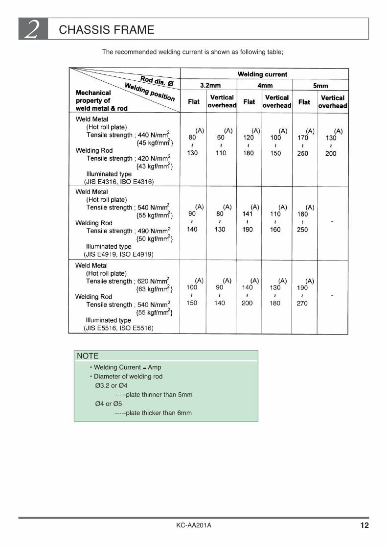
The recommended welding current is shown as following table;
NOTE • Welding Current = Amp
• Diameter of welding rod Ø3.2 or Ø4 -----plate thinner than 5mm Ø4 or Ø5 -----plate thicker than 6mm

CHASSIS FRAME2
KC-AA201A 13
After operation (anticorrosive treatment of weld zone)
Take an appropriate anticorrosive measure after welding a corrosive portion.
[ Anticorrosive measure ]
Brush off dust from the weld zone.
Primer surfacer (primer coating) Apply the wash primer.• A major potion of the wash primer is composed of vinyl butyral resin and zinc chromate
(anticorrosive pigment).• The dry film thickness is 5 to 10 microns/coat.
Top coating Use a natural dry type paint or a double coat type paint in top coating.• The dry film thickness is 30 microns/coat minimum.
Salt spray resistance Conduct the salt spray test for 840 hours in succession according to ASTM B117. Make sure that no rust settles on the general surface other than the weld beads.
Welding Side Members
Don’t weld in the upper and lower surface of the flanges.
Keep the welding point away from the flange bend by 30mm minimum.
Be sure that the welding bead is distant by 30mm minimum from the hole edge.

CHASSIS FRAME2
KC-AA201A 14
4. SIDE MEMBER REINFORCEMENT
The breakage or cracking of the side member is usually caused by stress concentration due to a local cut, welding or concentrated load or sudden rigidity change caused by upper parts rather than by the maximum stress which would be exerted in calculation. For this reason, the reinforcement by an outer or inner stiffener is not generally required.• The large-scale repair of the side member should be avoided as far as possible.• In the case where reinforcement is unavoidable due to special body or equipment
mounting (e.g. a small crane mounted behind the cab), modification or operating conditions, take adequate care of the following points.
Material of Reinforcing Member
When the outer side of the side member is reinforced, use a material at least equivalent to the main and inner materials.
In applying a reinforcing plate on the inside of the side member, use a general frame steel plate Hino standard SAPH440 with tensile strength of 440N/mm2 {45kgf/mm2} or an item equivalent to SS41P.
CHASSIS FRAME2
KC-AA201A 15
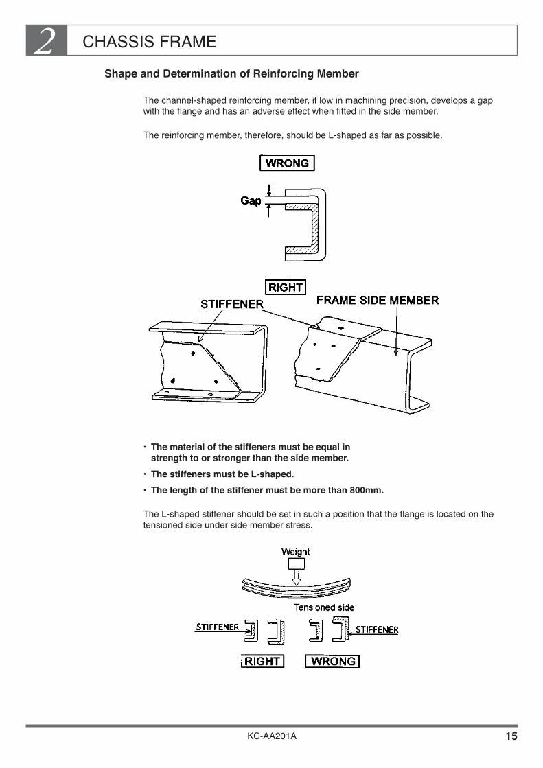
Shape and Determination of Reinforcing Member
The channel-shaped reinforcing member, if low in machining precision, develops a gap with the flange and has an adverse effect when fitted in the side member.
The reinforcing member, therefore, should be L-shaped as far as possible.
• The material of the stiffeners must be equal in strength to or stronger than the side member.
• The stiffeners must be L-shaped.• The length of the stiffener must be more than 800mm.
The L-shaped stiffener should be set in such a position that the flange is located on the tensioned side under side member stress.

CHASSIS FRAME2
KC-AA201A 16
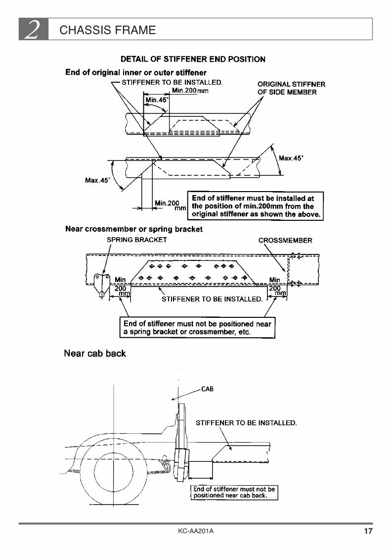
If the end of the outer stiffener is registered with the end of the inner stiffener or the portion of the cross beam or spring bracket subjected to a sudden rigidity change or load concentration, a cracking is liable to occur more easily.
Take adequate care in determining the position of the stiffener end.
• The end of the stiffener, mentioned right side figure, must not come to following positions.
CHASSIS FRAME2
KC-AA201A 17
CHASSIS FRAME2
KC-AA201A 18
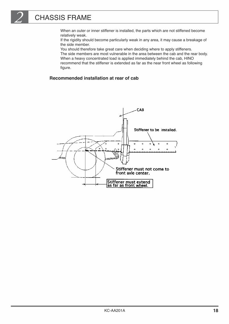
When an outer or inner stiffener is installed, the parts which are not stiffened become relatively weak. If the rigidity should become particularly weak in any area, it may cause a breakage of the side member. You should therefore take great care when deciding where to apply stiffeners. The side members are most vulnerable in the area between the cab and the rear body. When a heavy concentrated load is applied immediately behind the cab, HINO recommend that the stiffener is extended as far as the near front wheel as following figure.
Recommended installation at rear of cab
CHASSIS FRAME2
KC-AA201A 19
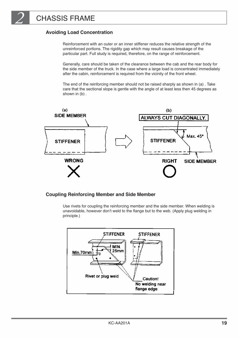
Avoiding Load Concentration
Reinforcement with an outer or an inner stiffener reduces the relative strength of the unreinforced portions. The rigidity gap which may result causes breakage of the particular part. Full study is required, therefore, on the range of reinforcement.
Generally, care should be taken of the clearance between the cab and the rear body for the side member of the truck. In the case where a large load is concentrated immediately after the cabin, reinforcement is required from the vicinity of the front wheel.
The end of the reinforcing member should not be raised sharply as shown in (a) . Take care that the sectional slope is gentle with the angle of at least less then 45 degrees as shown in (b) .
Coupling Reinforcing Member and Side Member
Use rivets for coupling the reinforcing member and the side member. When welding is unavoidable, however don’t weld to the flange but to the web. (Apply plug welding in principle.)

CHASSIS FRAME2
KC-AA201A 20
Before repeated riveting, correct the hole by drilling and apply a sufficient pressure.• In the case where the number of sheets fastened is increased by setting a reinforcing
member, use a rivet having the next larger diameter.• After riveting work, see that the rivet is not heated by gas
flame or the like.
How to rivet, have to work as shown below.
In conducting the plug welding work, keep the plug-welding hole away from the end of the reinforcing member by 25mm minimum and from the bolt and the rivet hole by 70mm minimum.• The hole diameter should be in the range of 14 to 20mm in principle.

CHASSIS FRAME2
KC-AA201A 21
5. OTHER PRECAUTIONS FOR DRILLING AND ELECTRICAL WELDING
Do Not Heat the Frame Unnecessarily
Heating greatly affects the strength of the frame. Do not unnecessarily heat any part of the frame unless performing welding work on the web surface of the side member or gas cutting work on the rear overhang.
Never Make Cutouts in Flanges
Do not make cutouts in the flanges of the side members when mounting the body or making modifications. Cutouts may lead to cracks in the side members.
Do Not Drill, Weld or Make Cutouts in Crossmembers
The crossmembers which link the right and left side members are important strengthening parts. When mounting the body or making modifications, do not drill, weld or make cutouts in the crossmembers.
CHASSIS FRAME2
KC-AA201A 22
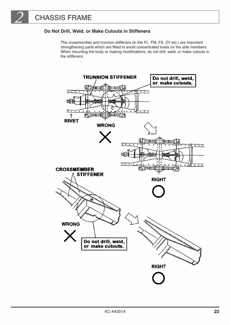
Do Not Drill, Weld, or Make Cutouts in Stiffeners
The crossmember and trunnion stiffeners (in the FL, FM, FS, ZY etc.) are important strengthening parts which are fitted to avoid concentrated loads on the side members. When mounting the body or making modifications, do not drill, weld, or make cutouts in the stiffeners.

CHASSIS FRAME2
KC-AA201A 23
Do Not Modify the Crossmember
When accommodating body side devices within the chassis frame, you should not modify crossmembers of the chassis frame. If an equipment or a device comes across over the crossmember section or if a sufficient clearance is not available, apply an appropriate solution by moving the fitting position of the said equipment or device, etc.

CHASSIS FRAME2
KC-AA201A 24
6. EXTENSION OF SIDE MEMBER REAR END
The chassis frame is an important strengthening part of the vehicle. As a rule, modifications such as lengthening are forbidden. If you must lengthen the rear end, observe the following precautions: The length of the rear end after extension must be no more than 1/2 the length of the wheel base. However, in van and tank bodies where the cargo will never stick out beyond the end of body, the rear end may be up to 2/3 the length of the wheel base.
When the Extension is 300 mm or Less
Extension material
The material of the extension must be the same as the base material of the main members and inner stiffeners.
How to make an extension
Use a welding rod designed for use with the base metal. Use continuous butt welding for the extension material and intermittent welding for stiffeners of 35mm in circumference. Always fit stiffeners of the same length as the extension.
The same length as the extension of the frame
Extension
up to 300
Original frame
Min. 10mm
4.5
12
1
9 A
Same thickness as side member
A = 2/3 x side member height
70°Scrape off the excess metal to the surface of the base metal.
Main member
L-shaped stiffenerDetailed view of B
B
CHASSIS FRAME2
KC-AA201A 25
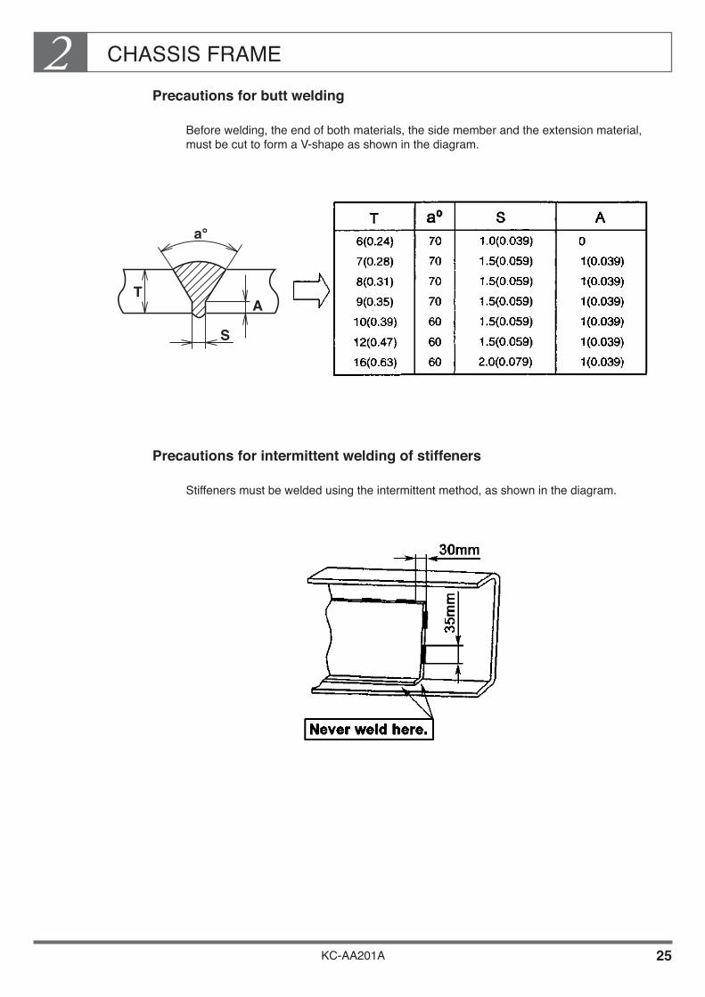
Precautions for butt welding
Before welding, the end of both materials, the side member and the extension material, must be cut to form a V-shape as shown in the diagram.
Precautions for intermittent welding of stiffeners
Stiffeners must be welded using the intermittent method, as shown in the diagram.
A
S
T
a°
CHASSIS FRAME2
KC-AA201A 26
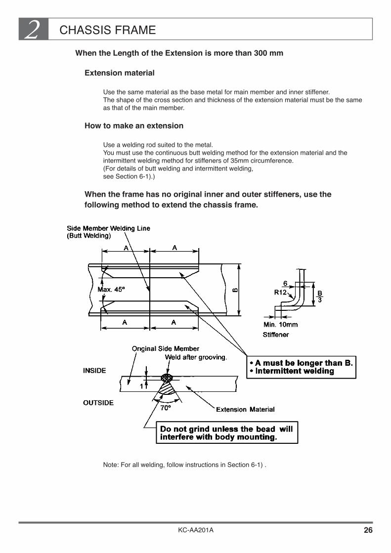
When the Length of the Extension is more than 300 mm
Extension material
Use the same material as the base metal for main member and inner stiffener. The shape of the cross section and thickness of the extension material must be the same as that of the main member.
How to make an extension
Use a welding rod suited to the metal. You must use the continuous butt welding method for the extension material and the intermittent welding method for stiffeners of 35mm circumference. (For details of butt welding and intermittent welding, see Section 6-1).)
When the frame has no original inner and outer stiffeners, use the following method to extend the chassis frame.
Note: For all welding, follow instructions in Section 6-1) .
CHASSIS FRAME2
KC-AA201A 27
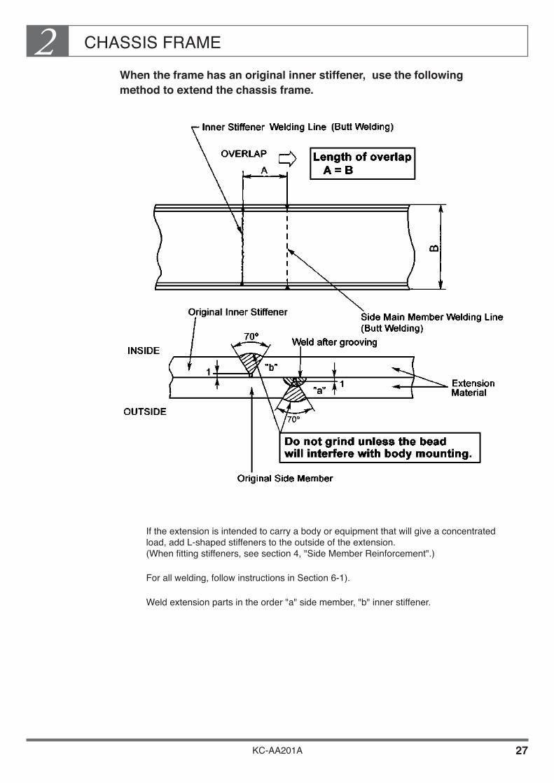
When the frame has an original inner stiffener, use the following method to extend the chassis frame.
If the extension is intended to carry a body or equipment that will give a concentrated load, add L-shaped stiffeners to the outside of the extension. (When fitting stiffeners, see section 4, "Side Member Reinforcement".)
For all welding, follow instructions in Section 6-1).
Weld extension parts in the order "a" side member, "b" inner stiffener.

CHASSIS FRAME2
KC-AA201A 28
When the frame has original inner and outer stiffeners, use the following method to extend the chassis frame.
If the extension is intended to carry a body or equipment that will give a concentrated load, add L-shaped outer stiffener such as to cover the extended welding part. (When fitting stiffeners, see Section 4, "Side Member Reinforcement".)
For all welding, follow instructions in Section 6-1).
Weld extension parts in the order "a" side member, "b" inner stiffener, "c" outer stiffener.

CHASSIS FRAME2
KC-AA201A 29
3) Placing the Final Crossmember After Making an Extension
After extending the rear overhang, be sure to fit a final crossmember.• Either move the original final crossmember to the end of the extension, or add a new
crossmember.• Secure the final crossmember using rivets or reamer bolts.
When securing with reamer bolts• Make sure that the bolt is not loose in its hold.
• Tighten the bolt using the prescribed torque, then use a punch or spot welding to fix the nut and prevent it from loosing.
Side Member
Original Crossmember
Extension Material
Secure with rivetsor reamer bolts.
CHASSIS FRAME2
KC-AA201A 30
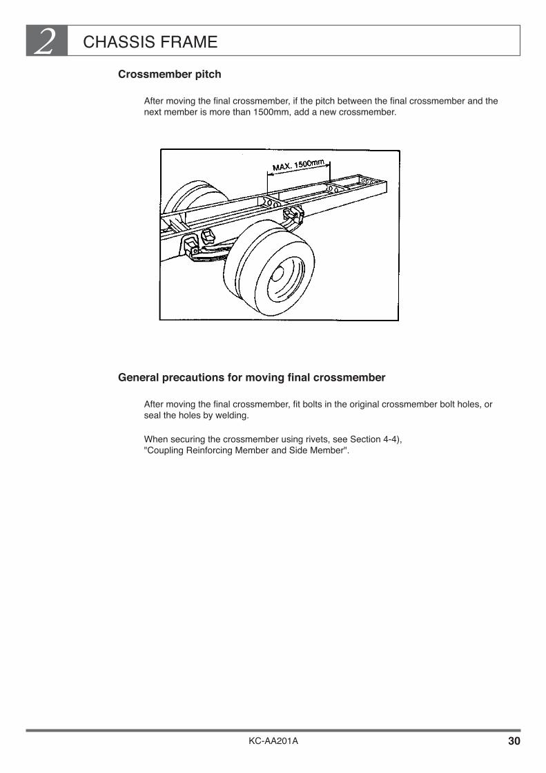
Crossmember pitch
After moving the final crossmember, if the pitch between the final crossmember and the next member is more than 1500mm, add a new crossmember.
General precautions for moving final crossmember
After moving the final crossmember, fit bolts in the original crossmember bolt holes, or seal the holes by welding.
When securing the crossmember using rivets, see Section 4-4), "Coupling Reinforcing Member and Side Member".
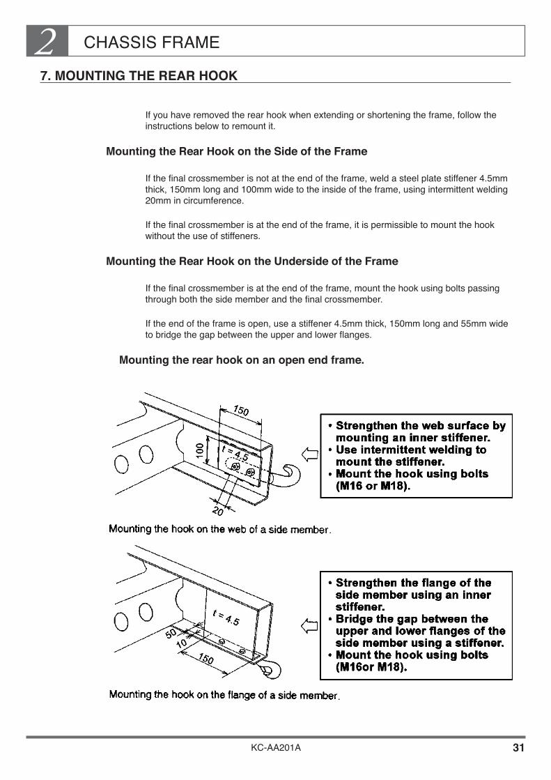
CHASSIS FRAME2
KC-AA201A 31
7. MOUNTING THE REAR HOOK
If you have removed the rear hook when extending or shortening the frame, follow the instructions below to remount it.
Mounting the Rear Hook on the Side of the Frame
If the final crossmember is not at the end of the frame, weld a steel plate stiffener 4.5mm thick, 150mm long and 100mm wide to the inside of the frame, using intermittent welding 20mm in circumference.
If the final crossmember is at the end of the frame, it is permissible to mount the hook without the use of stiffeners.
Mounting the Rear Hook on the Underside of the Frame
If the final crossmember is at the end of the frame, mount the hook using bolts passing through both the side member and the final crossmember.
If the end of the frame is open, use a stiffener 4.5mm thick, 150mm long and 55mm wide to bridge the gap between the upper and lower flanges.
Mounting the rear hook on an open end frame.
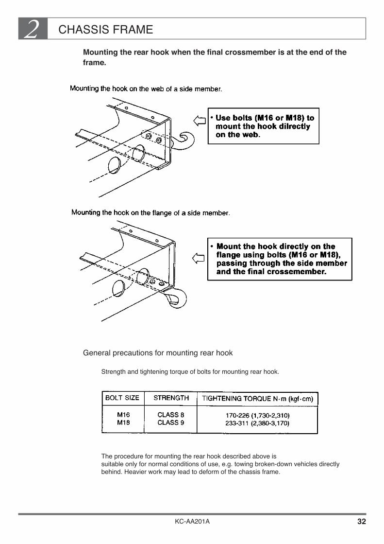
CHASSIS FRAME2
KC-AA201A 32
Mounting the rear hook when the final crossmember is at the end of the frame.
General precautions for mounting rear hook
Strength and tightening torque of bolts for mounting rear hook.
The procedure for mounting the rear hook described above is suitable only for normal conditions of use, e.g. towing broken-down vehicles directly behind. Heavier work may lead to deform of the chassis frame.

CHASSIS FRAME2
KC-AA201A 33
8. MOUNTING THE REAR PINTLE HOOK
If the vehicle will be used to tow trailers, etc., mount a pintle hook on the final crossmember according to the procedure below.• The original final crossmember is not sufficiently strong for the mounting of a pintle
hook. Remove the original crossmember and mount a reinforced crossmember with thicker section plate.
• The material of the reinforced crossmember must have a tensile strength 540 N/mm2 {55 kgf/mm2} or equivalent.
• Mount the reinforced crossmember securely using rivets or reamer bolts.
If you mount the crossmember using reamer bolts, after tightening the nuts, use a punch or spot welding to fix the nuts and prevent them from loosening.

KC-AA201A 34
CHASSIS FRAME2Details of Reinforced Crossmember (For Reference)
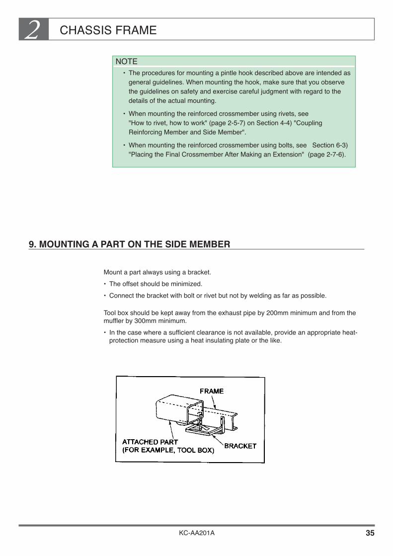
CHASSIS FRAME2
KC-AA201A 35
9. MOUNTING A PART ON THE SIDE MEMBER
Mount a part always using a bracket.• The offset should be minimized.• Connect the bracket with bolt or rivet but not by welding as far as possible.
Tool box should be kept away from the exhaust pipe by 200mm minimum and from the muffler by 300mm minimum.• In the case where a sufficient clearance is not available, provide an appropriate heat-
protection measure using a heat insulating plate or the like.
NOTE• The procedures for mounting a pintle hook described above are intended as
general guidelines. When mounting the hook, make sure that you observe the guidelines on safety and exercise careful judgment with regard to the details of the actual mounting.
• When mounting the reinforced crossmember using rivets, see "How to rivet, how to work" (page 2-5-7) on Section 4-4) "Coupling Reinforcing Member and Side Member".
• When mounting the reinforced crossmember using bolts, see Section 6-3) "Placing the Final Crossmember After Making an Extension" (page 2-7-6).

KC-AA201A
Chapter 3ENGINE AND ENGINE COMPARTMENT
1. PRECAUTIONS FOR MOUNTING OR MODIFICATION (ALTERATION) •••••••••••••••••••••••••• 2

ENGINE AND ENGINE COMPARTMENT3
KC-AA201A 1
The engine is the most important component part of any vehicle. To ensure that it remains in optimum condition requires regular inspection, maintenance and repair work.
When mounting a rear body or equipment, you should therefore observe the precautions and procedures described in this section and be sure to allow for ease of regular inspection, maintenance and repair work.
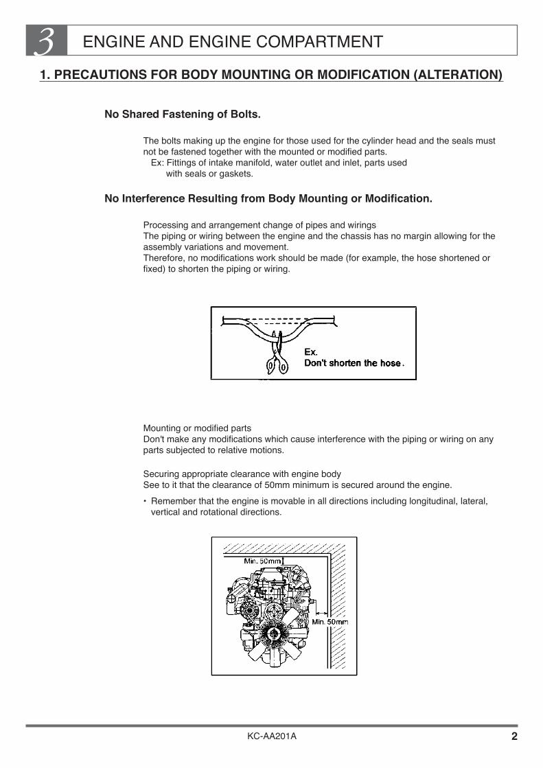
ENGINE AND ENGINE COMPARTMENT3
KC-AA201A 2
1. PRECAUTIONS FOR BODY MOUNTING OR MODIFICATION (ALTERATION)
No Shared Fastening of Bolts.
The bolts making up the engine for those used for the cylinder head and the seals must not be fastened together with the mounted or modified parts. Ex: Fittings of intake manifold, water outlet and inlet, parts used with seals or gaskets.
No Interference Resulting from Body Mounting or Modification.
Processing and arrangement change of pipes and wirings The piping or wiring between the engine and the chassis has no margin allowing for the assembly variations and movement. Therefore, no modifications work should be made (for example, the hose shortened or fixed) to shorten the piping or wiring.
Mounting or modified parts Don't make any modifications which cause interference with the piping or wiring on any parts subjected to relative motions.
Securing appropriate clearance with engine body See to it that the clearance of 50mm minimum is secured around the engine.• Remember that the engine is movable in all directions including longitudinal, lateral,
vertical and rotational directions.

ENGINE AND ENGINE COMPARTMENT3
KC-AA201A 3
Heat Consideration (piping and wiring, resin clamp, accelerator wire, fuel system, etc.)
When installing any of the above-described parts in the vicinity of the exhaust manifold or exhaust system, take adequate care of heat resistance.
• Secure a construction free of interference in case of assembly variations or clamp dislocation. In particular, secure a sufficient clearance for the accelerator wire from the heat source (200mm at minimum from the exhaust pipe).
• In the event that the defined clearance is unavailable, protect against heat by means of a heat insulating plate or the like.
The resin clamp may be softened by the heat from the engine compartment and may be dislocated. Take good care.

ENGINE AND ENGINE COMPARTMENT3
KC-AA201A 4
Cooling
Don't make any mounting or modifications which may reduce the cooling performance.
Don't mount any parts at a position where the exhaust manifold is exposed to less air.
Don't change the fan shroud coverage on the fan nor add any fan shroud cut as it would deteriorate the cooling performance.
The seals (sponge, rubber plate and the like) around the radiator are mounted for the purpose of securing the cooling performance. Don't remove them or cut a recess in them.

ENGINE AND ENGINE COMPARTMENT3
KC-AA201A 5
Don't take off or cut the protector, cover, heat insulator or the like mounted around the engine.
No Modifications to Increase Intake or Exhaust Air Resistance
Don't make any modifications to the air cleaner.
Don't extend or make any modifications to the arrangement of the air intake system.
Don't extend or make any modifications to the arrangement of the exhaust pipe.
Don't make any modifications to the muffler.
Mounting or Modifications of the Parts
Mounting on engine body In mounting a part on the engine body, place it nearer to the engine (with a smaller overhang) and reduce the weight as far as possible.
Mounting bolts Make sufficient study of the lap allowance and the bottom fitting of the bolt to be mounted.
Cooling fan belt change Don't reduce the number of existing belts and avoid the case of a belt being shared.

ENGINE AND ENGINE COMPARTMENT3
KC-AA201A 6
Pulley addition• When adding a crank pulley, minimize the offset from the mounting position and reduce
the weight as far as possible.• Don't excessively advance the fan (coupling) as a result of pulley addition as it could
deteriorate the durability of the water pump.
Taking Out of Auxiliary Power
Don't take auxiliary power out except crankshaft pulley and engine rear P. T. O.
Idling-Up Device
In the case to mount the engine idling-up device, make sure that don't change for the worse of driving ability. (Ex; quick starting the vehicle, for the worse of engine brake, etc.)
Mounting and Dismounting Engine Parts
In reassembling an engine part, always make sure to comply with the Workshop Manual issued by the Overseas Product Support Division. (Don't reuse the gasket, strictly conform to the tightening torque requirement, etc.)
Serviceability
See to it that the following jobs are not adversely affected by the particular mounting or modifications.• Oil level check• Oil change (oil drain or filling)• Change of oil filter• Adjustment of fan belt tension• Change of air cleaner element• Change of fuel filter• Adjustment of idle rpm, CO and HC• Adjustment of valve clearance• Adjustment of injection timing• Change of injection nozzle• Change of glow plug etc.

KC-AA201A
Chapter 4PROPELLER SHAFT
1. PROPELLER SHAFT ••••••••••••••••••••••••••••••••••••••••••• 1

PROPELLER SHAFT4
KC-AA201A 1
1. PROPELLER SHAFT
The propeller shaft is an important component that transfers drive power generated by the engine to the rear axle. The propeller shaft rotates at high speeds while operating making it a very dangerous component.
Accordingly, when mounting a body or equipment, be sure to observe the instructions given below.
Prohibited Modifications and Alterations
Careless modifications will result in vibrations and unusual noises while the vehicle is driving and are very dangerous. These type of modifications must not be carried out.
Confirming Correct Clearance
The propeller shaft rotates at high speeds while simultaneously vibrating up and down and right and left along the road surface.
Accordingly, the clearance between the propeller shaft (including joints) and the body or body equipment parts must be at least 50mm from the limit of displacement of the propeller shaft (above, below, right, left and front or back of the rear axle).

KC-AA201A
Chapter 5BRAKE & HYDRAULIC PIPING
1. GENERAL POINTS OF BRAKE SYSTEM ••••••••••••••••• 2 2. BRAKE PIPING USED IN THE CHASSIS ••••••••••••••••• 6 3. PRECAUTIONS WHEN MOUNTING A BODY
OR EQUIPMENT ••••••••••••••••••••••••••••••••••••••••••••• 8 4. PRECAUTIONS FOR MODIFICATION
(ALTERATION) •••••••••••••••••••••••••••••••••••••••••••••••• 12 5. PIPING CLEARANCES •••••••••••••••••••••••••••••••••••••••• 16 6. CLIPPING OF PIPING •••••••••••••••••••••••••••••••••••••••••• 19 7. PRECAUTIONS TO TAKE WHEN HANDLING
NYLON TUBES FOR BRAKES ••••••••••••••••••••••••••• 20

BRAKE & HYDRAULIC PIPING5
KC-AA201A 1
The brake system is an extremely important safety component of the vehicle.
Incorrect body or equipment mounting may have a major impact on the functions and performance of the brake system and may lead to serious mechanical failures or accidents.
When mounting a body or equipment making alterations, strictly observe the following precautions:
[EXAMPLE BRAKE PIPING DIAGRAM]
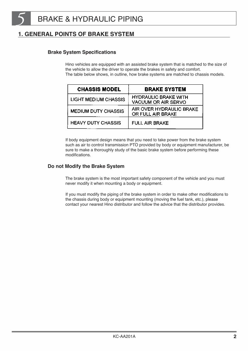
BRAKE & HYDRAULIC PIPING5
KC-AA201A 2
1. GENERAL POINTS OF BRAKE SYSTEM
Brake System Specifications
Hino vehicles are equipped with an assisted brake system that is matched to the size of the vehicle to allow the driver to operate the brakes in safety and comfort. The table below shows, in outline, how brake systems are matched to chassis models.
If body equipment design means that you need to take power from the brake system such as air to control transmission PTO provided by body or equipment manufacturer, be sure to make a thoroughly study of the basic brake system before performing these modifications.
Do not Modify the Brake System
The brake system is the most important safety component of the vehicle and you must never modify it when mounting a body or equipment.
If you must modify the piping of the brake system in order to make other modifications to the chassis during body or equipment mounting (moving the fuel tank, etc.), please contact your nearest Hino distributor and follow the advice that the distributor provides.
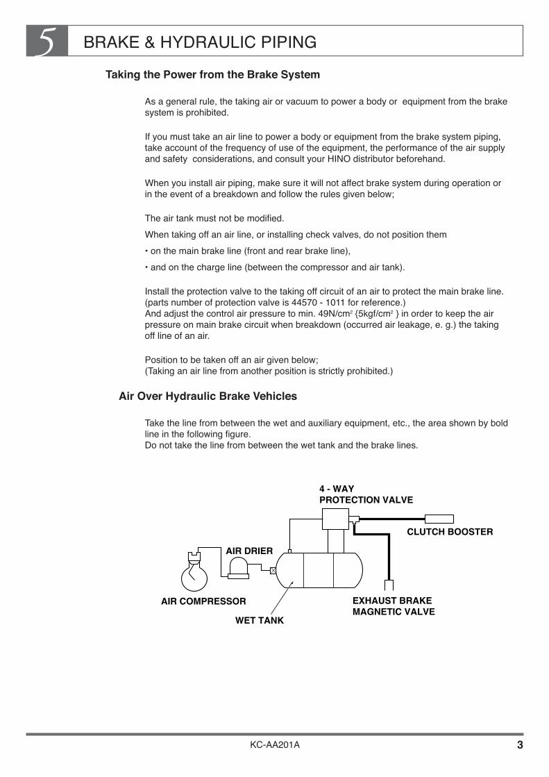
BRAKE & HYDRAULIC PIPING5
KC-AA201A 3
Taking the Power from the Brake System
As a general rule, the taking air or vacuum to power a body or equipment from the brake system is prohibited.
If you must take an air line to power a body or equipment from the brake system piping, take account of the frequency of use of the equipment, the performance of the air supply and safety considerations, and consult your HINO distributor beforehand.
When you install air piping, make sure it will not affect brake system during operation or in the event of a breakdown and follow the rules given below;
The air tank must not be modified.When taking off an air line, or installing check valves, do not position them• on the main brake line (front and rear brake line),• and on the charge line (between the compressor and air tank).
Install the protection valve to the taking off circuit of an air to protect the main brake line. (parts number of protection valve is 44570 - 1011 for reference.) And adjust the control air pressure to min. 49N/cm2 {5kgf/cm2 } in order to keep the air pressure on main brake circuit when breakdown (occurred air leakage, e. g.) the taking off line of an air.
Position to be taken off an air given below; (Taking an air line from another position is strictly prohibited.)
Air Over Hydraulic Brake Vehicles
Take the line from between the wet and auxiliary equipment, etc., the area shown by bold line in the following figure. Do not take the line from between the wet tank and the brake lines.
WET TANK
EXHAUST BRAKEMAGNETIC VALVE
AIR DRIER
CLUTCH BOOSTER
4 - WAYPROTECTION VALVE
AIR COMPRESSOR

BRAKE & HYDRAULIC PIPING5
KC-AA201A 4
Full Air Brake Vehicles
Take the line from the plug of the wet tank.
[ Example Piping Diagram ]
BODYEQUIPMENT
WET TANK
EXHAUST BRAKEMAGNETIC VALVE
AIR DRIER
CLUTCH BOOSTER
4 - WAYPROTECTION VALVE
AIR COMPRESSOR
INSTALLPROTECTION VALVE

BRAKE & HYDRAULIC PIPING5
KC-AA201A 5
Refilling Brake Fluid
When changing brake and clutch fluids, use only genuine HINO brake and clutch fluids. (For details of brake and clutch fluids, see the appropriate workshop or maintenance guides.)
Never reuse old brake or clutch fluids. Never use mineral oil or mix HINO products with other brands of fluid.
Avoiding Effect of Exhaust Heat
Locate the brake hoses, pipes and nylon tubes min. 200 mm away from the exhaust system. When the specified clearance can not be made available, protect against heat by such means as a heat insulating plate.
Locate the parking brake outer cable min. 200 mm away from the exhaust system. When the specified clearance can not be provided, protect them against heat by such means as a heat insulating plate.

BRAKE & HYDRAULIC PIPING5
KC-AA201A 6
2. BRAKE PIPING USED IN THE CHASSIS
Steel Piping Used in the Chassis
The table below shows the material of the piping used in the chassis and the configuration of the flare of each type of pipe.
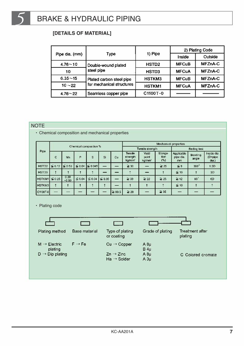
BRAKE & HYDRAULIC PIPING5
KC-AA201A 7
[DETAILS OF MATERIAL]
NOTE• Chemical composition and mechanical properties
• Plating code

BRAKE & HYDRAULIC PIPING5
KC-AA201A 8
3. PRECAUTIONS WHEN MOUNTING A BODY OR EQUIPMENT
Avoiding Interference with Piping
Take care that the piping is not caught by other parts.
Be sure that the piping is not flattened.
See to it that the piping is not in contact with the sharp-angle portion of other parts.
Pay attention to the displacement of the brake hose connected to the front and rear wheels while the vehicle is running.
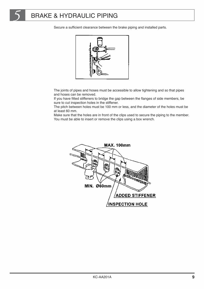
BRAKE & HYDRAULIC PIPING5
KC-AA201A 9
Secure a sufficient clearance between the brake piping and installed parts.
The joints of pipes and hoses must be accessible to allow tightening and so that pipes and hoses can be removed. If you have fitted stiffeners to bridge the gap between the flanges of side members, be sure to cut inspection holes in the stiffener. The pitch between holes must be 100 mm or less, and the diameter of the holes must be at least 60 mm. Make sure that the holes are in front of the clips used to secure the piping to the member. You must be able to insert or remove the clips using a box wrench.

BRAKE & HYDRAULIC PIPING5
KC-AA201A 10
Make sure that brake component parts are easily accessible.• Drains are fitted under the air tank and relay valve. When mounting a body or
equipment, make sure that the drains are easily accessible.• Make sure that the following parts are easily accessible for maintenance and
replacement: Air dryer Pressure regulator Check valve Release valve Quick release valve Safety valve Spring brake control valve Hydro master Safety cylinder Spring brake release valve Brake booster• In vehicles with hydraulic brakes, make sure that the air bleeders of following parts are
easily accessible for air bleeding: Brake booster Hydro master Wheel cylinder
Allow sufficient clearance between the brake pipes, hoses, nylon tubes and mounted body or equipment. When mounting the body or equipment, make sure that body and equipment do not interfere with the brake system.• Clearance with engine• Clearance with brake component parts
(pipes, hoses, nylon tubes,devices of ABS & LSV, etc.)• Clearance with hoses around axles
(must be consider the maximum movement of axles)• Clearances with dump body parts
(moving parts such as hydraulic cylinder, dump arm etc.)• Clearances with rubber parts
(For more details of required clearances, see after clause “ 5. PIPING CLEARANCE ”.)
The above precautions also apply to the valves and piping of special equipment such as ABS (anti-lock brake system), LSV (load sensing proportioning valve.)

BRAKE & HYDRAULIC PIPING5
KC-AA201A 11
Antidewing and anticorrosion of piping Corrosion of the brake piping for the special rear bodies of the liquid oxygen truck, the vacuum tank truck or fresh fish truck is promoted by the dew or water at low-temperature portions (such as the liquid oxygen inlet/outlet). Keep the brake piping away from or cover it with a protective plate at portions where dew forms or water drops easily.
When remove the LSV during body mounting or alteration, it must be readjusted. (For the adjustment procedure, refer to the Owner’s or Workshop Manual.)

BRAKE & HYDRAULIC PIPING5
KC-AA201A 12
4. PRECAUTIONS FOR MODIFICATION (ALTERATION)
As far as possible avoid modifying any piping. If you modify piping, be sure to observe the following precautions.
PIPING
When extending a pipe, do not join two pipes directly.
When joining pipes, use the flare joint method and avoid twisting the pipes too much.
Most pipes are made of steel but have anti-corrosive plating on the inside. Never braze these pipes and never heat them to high temperatures.
Do not use copper pipes for high-pressure hydraulic brake piping and for piping in areas below unsprung parts as on axles.
NOTETightening torque of flare nut
Do not weld brake piping and do not heat to high temperatures.
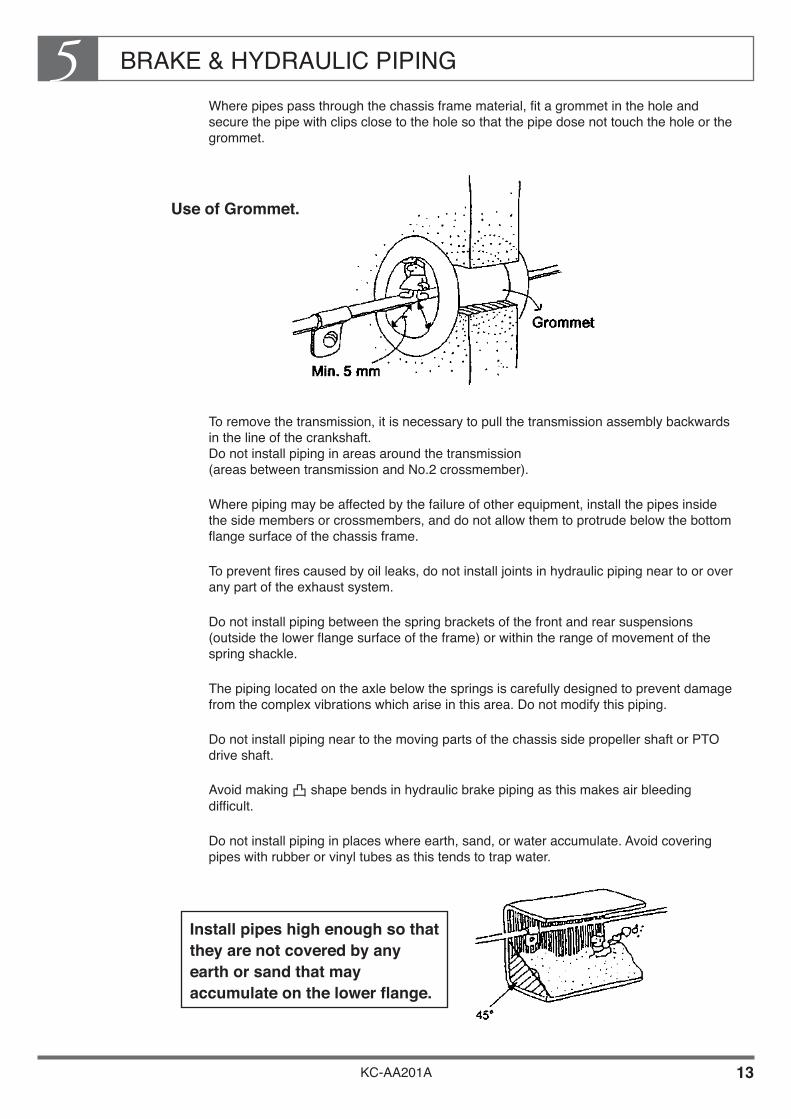
BRAKE & HYDRAULIC PIPING5
KC-AA201A 13
Where pipes pass through the chassis frame material, fit a grommet in the hole and secure the pipe with clips close to the hole so that the pipe dose not touch the hole or the grommet.
Use of Grommet.
To remove the transmission, it is necessary to pull the transmission assembly backwards in the line of the crankshaft. Do not install piping in areas around the transmission (areas between transmission and No.2 crossmember).
Where piping may be affected by the failure of other equipment, install the pipes inside the side members or crossmembers, and do not allow them to protrude below the bottom flange surface of the chassis frame.
To prevent fires caused by oil leaks, do not install joints in hydraulic piping near to or over any part of the exhaust system.
Do not install piping between the spring brackets of the front and rear suspensions (outside the lower flange surface of the frame) or within the range of movement of the spring shackle.
The piping located on the axle below the springs is carefully designed to prevent damage from the complex vibrations which arise in this area. Do not modify this piping.
Do not install piping near to the moving parts of the chassis side propeller shaft or PTO drive shaft.
Avoid making shape bends in hydraulic brake piping as this makes air bleeding difficult.
Do not install piping in places where earth, sand, or water accumulate. Avoid covering pipes with rubber or vinyl tubes as this tends to trap water.
Install pipes high enough so that they are not covered by any earth or sand that may accumulate on the lower flange.

BRAKE & HYDRAULIC PIPING5
KC-AA201A 14
To prevent from water, stone splashed by tire, locate the piping inside of frame or behind crossmember. (must be away the piping min. 5mm from frame and crossmember.)
Don’t locate the piping behind the end of the exhaust tail pipe.
When bending pipes, observe the following precautions:• Use a bender and do not heat the pipes in order to bend them.• Observe the standard bending radiuses shown in the table below
• The minimum lengths of the straight section at the end of a pipe and of the straight section between two bends are shown in the drawing below.
• Flush the inside of the pipe and remove any foreign matter before use. Use compressed air to flush the pipe.
• For details of pipe machining at the flare nut, see clause 2 of this section, "Brake Piping Used in the Chassis". After machining, remove any foreign matter by flushing the pipe with compressed air.
Make sure that there are not to much slack and giving tension to the piping.

BRAKE & HYDRAULIC PIPING5
KC-AA201A 15
Using sealing agents on tapers• If possible, use a strong anaerobic sealing agent(Genuine HINO product or locktight
#575).• Clean tapers with cotton waste and thinners before coating with sealing agent. If you
intend to reuse joints which have been sealed with anaerobic sealing agent or vulcanized tape., make sure you remove all trace of the old sealing agent or tape before re-sealing.
• Always apply sealing agent starting at one flat from the tip of the male thread, and apply the agent across three flats over one quarter of the circumference of the thread. Apply approximately 0.1 g of agent to each joint.
• When using vulcanized tape, make sure that the sealing agent does not penetrate any valve, etc. (If the sealing agent penetrate a valve, it may block the valve.) As a standard, leave two flats from the tip of the thread and apply 1.5 ~ 2 turns of vulcanized tape.
Inspection after fitting
After tightening the joint, • Make sure that there are no air or oil leaks.• Make sure that the fitting does not place any strain on the pipe or hose(bending,
distortion, etc.).

BRAKE & HYDRAULIC PIPING5
KC-AA201A 16
5. PIPING CLEARANCES
To prevent rust and damage from contact with other parts. When modifying piping, observe the following precautions.
Clearances Between Two Pipes
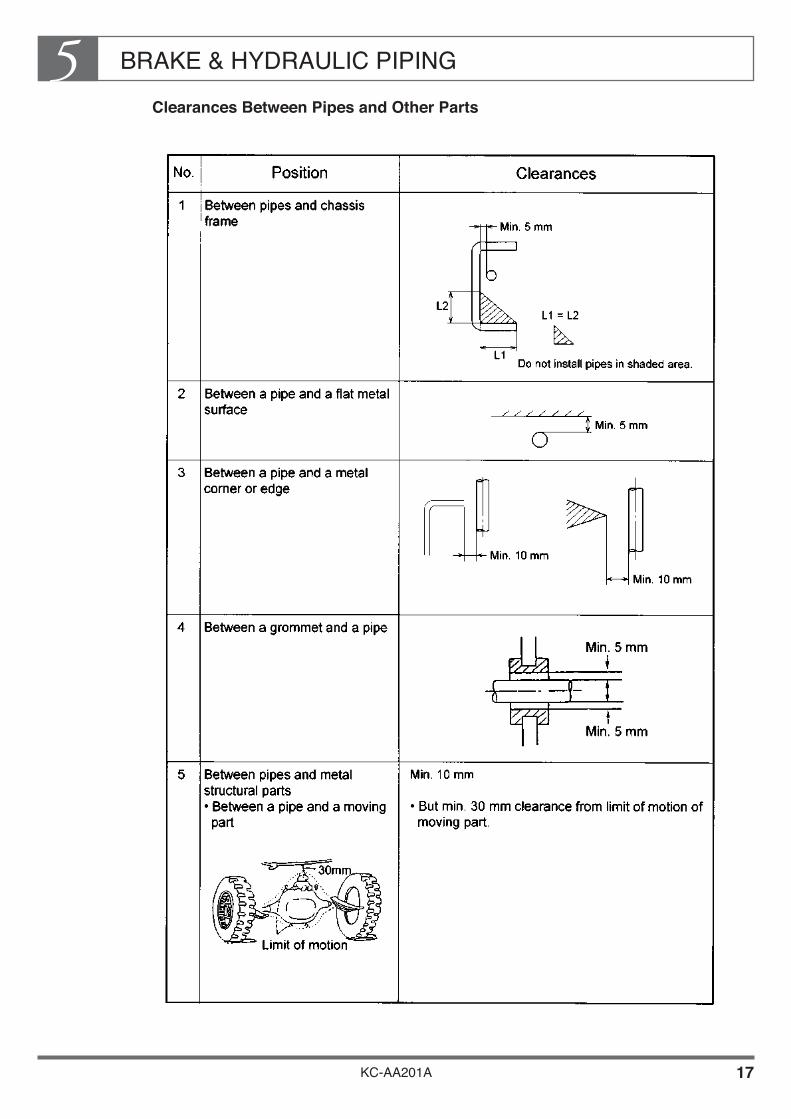
BRAKE & HYDRAULIC PIPING5
KC-AA201A 17
Clearances Between Pipes and Other Parts

BRAKE & HYDRAULIC PIPING5
KC-AA201A 18

BRAKE & HYDRAULIC PIPING5
KC-AA201A 19
6. CLIPPING OF PIPING
Pipes must be secured with clips to prevent them from swinging due to the motion of the vehicle. Use vinyl-coated or rubber-coated clips and follow the rules given in the table below.

BRAKE & HYDRAULIC PIPING5
KC-AA201A 20
7. PRECAUTIONS TO TAKE WHEN HANDLING NYLON TUBES FOR BRAKES
When nylon tubes are used in the air piping system of brakes, be careful so that they might not be heated particularly at the time of welding. Also, make sure to perform the welding by putting protecting covers on the nylon tubes so that welding sputter, etc. might not be splashed on the tubes. For other general precautions, refer to the instructions shown on the following table. When dismounting and remounting the piping for the reason of facilitating the maintenance, inspection of the brake and air line as well as of body or equipment mounting, make sure to put matching marks (using paint, tape, tag, etc.) on the equipment side as well as on the piping side to prevent by all means from making wrong fitting when remounting them. Wrong mounting of equipment and piping will cause a serious functional damage to the system using brake line and air line.

BRAKE & HYDRAULIC PIPING5
KC-AA201A 21
Precautions to take for handling nylon tubes when mounting the body
Protection of nylon tube when welding or grinding with a sander
Fit a protecting cover on the nylon tube or remove it according to the necessity
If welding sparks, etc are projected on the nylon tube, the tube may melt and cause air leakage sometimes.
1
Prevention of introduction of foreign matters into the nylon tubes and connectors.
When dismounting and remounting the nylon tubes and the connectors, cover them with vinyl sac, etc (sac producing fiber dust is not suitable) to prevent sticking and / or introduction of foreign matters.
Biting of foreign matters by valves and connectors may sometimes cause air leakage or malfunctioning of valves.
2
Protection against interference of nylon tubes
Matching parts Gap (mm) Holes may sometimes appear on the tubes and pipes due to rubbing and wear and may result in air leakage.
3
Securing gaps with exhaust system
Secure gaps of more than 200mmbetween the nylon tubes and the exhaust system (exhaust pipe, muffler, etc) or protect the tubes by covering them with insulators, etc. Also, be sure to fit insulators on the flange section of the exhaust system.
High temperature due to the heat of the exhaust system may cause sometimes melting of the tubes and may result in air leakage.
4
Chassis parts (fixing position)
5
Engine,transmission, cab, etc (relative moving position)
30
Tires, propeller shaft, etc (rotating position)
50
Components for upper structures
Equivalent to the above
Prevention of swinging of the nylon tubes
Provide appropriate clip bands to the nylon tubes to avoid swinging of the tubes after mounting. :• Gaps of the clip bands should have pitches less than 400mm.
• Clip band to use : 47837-1230
• Use the special service tool for clip band (09620-1010) with a fastening force of 3 indicated on the tool (dial adjusting type)
If the clip gap is too big, tubes may swing to rub against other parts and may cause contact wear, this leading sometime to occurrence of air leakage.
5
Securing of bending "R" for nylon tubes
The minimum bending "R" for the nylon tubes should be as indicated on the following table. Avoid bending the tubes with the bending "R" smallerthan the one indicated in the table.
R(mm)ø6 30
If a tube is bent with the bending "R" less than the minimum bending "R" ,,the air may be clogged by broken tube and air leakage may occur by the end position of the connector.
6
ø8 50ø10 65ø12 70ø15 80R

BRAKE & HYDRAULIC PIPING5
KC-AA201A 22
Spare parts Never fail to use genuine HINO spare parts. Otherwise, the nylon tube may be damaged. • Connectors for intermediate connection of nylon tubes
• Sleeve connectors
• Nylon tubes
• For one-touch type connectors, kindly contact authorized HINO distributor nearest to you.
10
Special service tools Use special service tools for dismounting and cutting nylon tubes. • Tools for dismounting nylon tubes HINO part number 09421-1560(release tool set) ø6 09421-1510(release tool) ø8 09421-1520(release tool) ø10 09421-1530(release tool) ø12 09421-1540(release tool) ø15 09421-1550(release tool)
• Nylon tube cutting tool HINO part number 09460-1020
• Clip band fastening tool HINO part number 09620-1010
11
Prevention of adherence of acidic liquid
As nylon tubes are weak against acid, be careful so that they might not be caught by battery liquid. Don't use waste cloth or cotton work gloves contaminated with battery liquid.
Sticking of acidic liquid such as battery liquid melts the tube and risks to cause air leakage.
7
Prevention of water penetration at the time of high pressure washing
Secure the distance minimum of 300mm and above between the connector and the injection port when performing high pressure washing.
If the distance between the connector and the injection port is not sufficient, water may penetrate into the piping, thus causing rusting, freezing, and malfunctioning of valves.
8
Protection of nylon tubes when performing forced drying of paint
As the temperature service limit of the nylon tube is from-40 to 100˚C, remove the nylon tube when using a drying booth whose service temperature exceeds this limit.
If this service limit is exceeded, air tightness of the tube will be reduced and may cause air leakage sometimes.
9
ø6 34801-2240ø8 34801-3070ø10 34801-2250ø12 34801-2260ø15 34801-2270
ø6 36769-282020mm
ø8 36769-3100ø10 36769-2830ø12 36769-2840ø15 36769-2850
Nut 23721-1070ø6
Sleeve 47983-1250Insert 47983-1260
23721-1150ø8
47983-175047983-1760
23721-1120ø10
47983-155047983-1560
23721-1090ø12
47983-140047983-1410
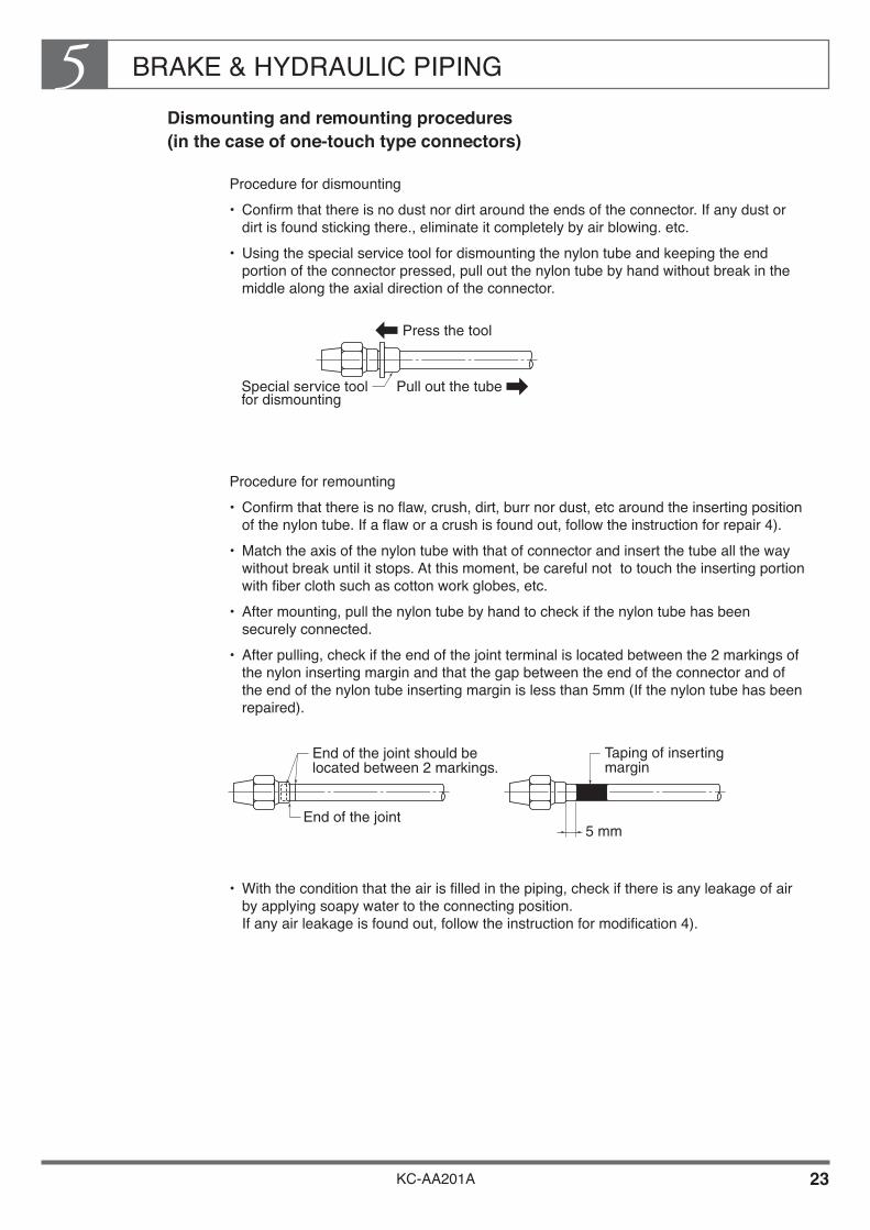
BRAKE & HYDRAULIC PIPING5
KC-AA201A 23
Dismounting and remounting procedures (in the case of one-touch type connectors)
Procedure for dismounting• Confirm that there is no dust nor dirt around the ends of the connector. If any dust or
dirt is found sticking there., eliminate it completely by air blowing. etc.• Using the special service tool for dismounting the nylon tube and keeping the end
portion of the connector pressed, pull out the nylon tube by hand without break in the middle along the axial direction of the connector.
Procedure for remounting• Confirm that there is no flaw, crush, dirt, burr nor dust, etc around the inserting position
of the nylon tube. If a flaw or a crush is found out, follow the instruction for repair 4).• Match the axis of the nylon tube with that of connector and insert the tube all the way
without break until it stops. At this moment, be careful not to touch the inserting portion with fiber cloth such as cotton work globes, etc.
• After mounting, pull the nylon tube by hand to check if the nylon tube has been securely connected.
• After pulling, check if the end of the joint terminal is located between the 2 markings of the nylon inserting margin and that the gap between the end of the connector and of the end of the nylon tube inserting margin is less than 5mm (If the nylon tube has been repaired).
• With the condition that the air is filled in the piping, check if there is any leakage of air by applying soapy water to the connecting position. If any air leakage is found out, follow the instruction for modification 4).
Special service tool for dismounting
Pull out the tube
Press the tool
End of the joint should be located between 2 markings.
End of the joint
Taping of inserting margin
5 mm

BRAKE & HYDRAULIC PIPING5
KC-AA201A 24
Dismounting and remounting procedures for nylon tubes (in the case of sleeve type connectors)
The sleeve type connector consists of a connector, nut, sleeve and an insert and the nut, sleeve and the insert are supplied as assembled by the manufacturer.
The nut, sleeve and the insert are not reusable once they are disassembled.
If repair is required, carry out the work according to the following procedure.
procedure for dismounting• Before loosening the nut, put the matching mark between the connector and the nut so
that the position can be visible. (marking by a magic ink is acceptable.)
• Loosen the nut and pull out the tube by hand in the axial direction while paying attention so that the sleeve and the insert may not fall off.
procedure for remounting • Put the nut and the sleeve onto the tube and put the insert into the tip of the tube. (Pay
attention to the remounting direction.)
• Drive the insert until the tip of the insert hits the connector while paying attention so that the nut, sleeve and the insert may not fall off and, under this condition, fully tighten the nut by hand.
• Hold the tube so that it may not move (comes off), tighten the nut up to the position before dismounting (matching mark) and retighten it by 60º. Further tighten the nut using the tool until the prescribed torque is obtained.
• Check the air leakage with a soapy water, etc. If any air leakage has been found out, retighten the nut until the air leakage stops.
Matching mark
Nylon tube Insert
Nut Sleeve Fastening type connector

BRAKE & HYDRAULIC PIPING5
KC-AA201A 25
•If the leakage does not stop, replace the tube, sleeve and the insert. If in spite of such replacement, the leakage does not stop, replace the nut and the connector in addition.
Procedure for repairing the nylon tube
When repair becomes necessary due to appearance of harmful defects such as breakage, crush, perforation, etc., carry out the repair according to the following instruction. (applicable only to the position which is not apparent such as the inside of the frame, etc.)• Prepare a nylon tube having the same size as that of the nylon tube to repair and a
connector for intermediate connection (exclusively for repair).
• Confirm the position of the defect on the nylon tube and decide the cutting position to such place where the connector is mountable. Use a cutter (special service tool) for cutting.
• Check if the cutting face of the nylon tube is smooth without any burr and that the cutting face is 90º±5º to the axis of the nylon tube.
• Wind the inserting margin taping according to the following table. (In the same way as in the case of one-touch type connector )
L
Connector for intermediate connection
ø6
OutsideDiameter of applicable tube
ø8ø10
34801-2240
Part number
34801-307034801-2250
16mm
Distance at the end of the tube
14mm10mm
ø1234801-2260 10mmø1534801-2270 6mm
Less than 5º
S
D
Inserting margin taping
ø6
D(Outside diameter
of tube)
ø8ø10
20.0±0.5
S(Inserting margin)
22.5±0.522.5±0.5
ø12 23.0±0.5ø15 24.5±0.5
Nut 23721-1070ø6
Sleeve 47983-1250Insert 47983-1260
23721-1150ø8
47983-175047983-1760
23721-1120ø10
47983-155047983-1560
23721-1090ø12
47983-140047983-1410
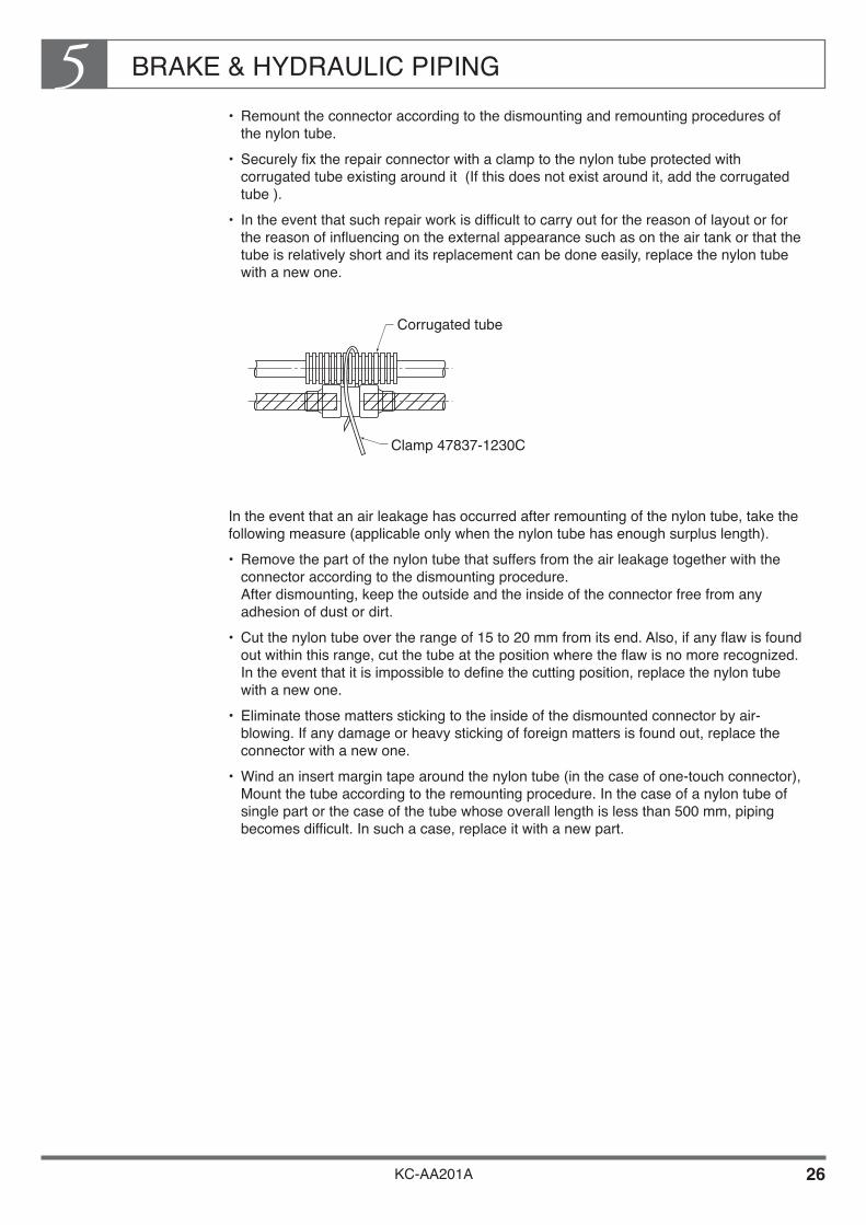
BRAKE & HYDRAULIC PIPING5
KC-AA201A 26
• Remount the connector according to the dismounting and remounting procedures of the nylon tube.
• Securely fix the repair connector with a clamp to the nylon tube protected with corrugated tube existing around it (If this does not exist around it, add the corrugated tube ).
• In the event that such repair work is difficult to carry out for the reason of layout or for the reason of influencing on the external appearance such as on the air tank or that the tube is relatively short and its replacement can be done easily, replace the nylon tube with a new one.
In the event that an air leakage has occurred after remounting of the nylon tube, take the following measure (applicable only when the nylon tube has enough surplus length).• Remove the part of the nylon tube that suffers from the air leakage together with the
connector according to the dismounting procedure. After dismounting, keep the outside and the inside of the connector free from any adhesion of dust or dirt.
• Cut the nylon tube over the range of 15 to 20 mm from its end. Also, if any flaw is found out within this range, cut the tube at the position where the flaw is no more recognized. In the event that it is impossible to define the cutting position, replace the nylon tube with a new one.
• Eliminate those matters sticking to the inside of the dismounted connector by air-blowing. If any damage or heavy sticking of foreign matters is found out, replace the connector with a new one.
• Wind an insert margin tape around the nylon tube (in the case of one-touch connector), Mount the tube according to the remounting procedure. In the case of a nylon tube of single part or the case of the tube whose overall length is less than 500 mm, piping becomes difficult. In such a case, replace it with a new part.
Clamp 47837-1230C
Corrugated tube
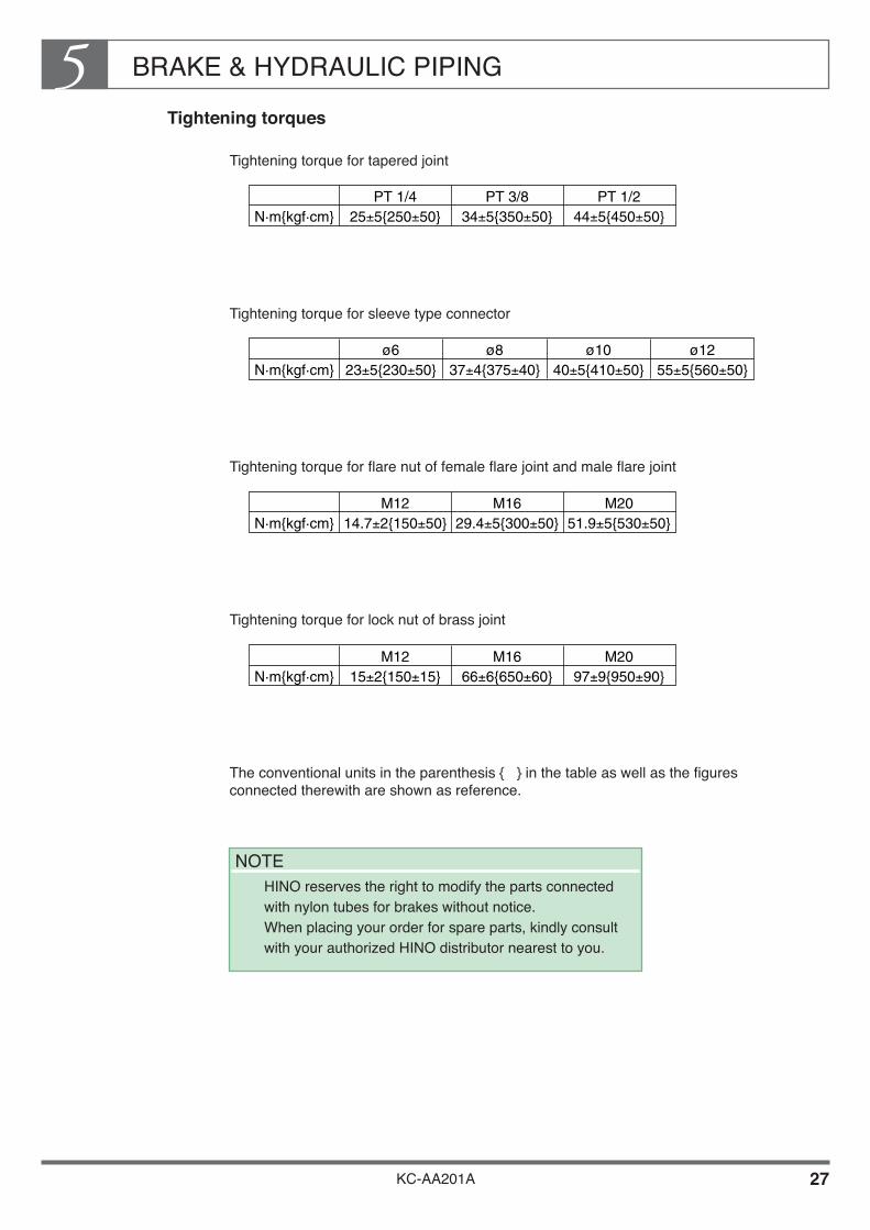
BRAKE & HYDRAULIC PIPING5
KC-AA201A 27
Tightening torques
Tightening torque for tapered joint
Tightening torque for sleeve type connector
Tightening torque for flare nut of female flare joint and male flare joint
Tightening torque for lock nut of brass joint
The conventional units in the parenthesis { } in the table as well as the figures connected therewith are shown as reference.
N·m{kgf·cm} 25±5{250±50}PT 1/4
34±5{350±50}PT 3/8
44±5{450±50}PT 1/2
N·m{kgf·cm} 23±5{230±50}ø6
37±4{375±40}ø8
40±5{410±50}ø10
55±5{560±50}ø12
N·m{kgf·cm} 14.7±2{150±50}M12
29.4±5{300±50}M16
51.9±5{530±50}M20
N·m{kgf·cm} 15±2{150±15}M12
66±6{650±60}M16
97±9{950±90}M20
NOTE HINO reserves the right to modify the parts connected
with nylon tubes for brakes without notice. When placing your order for spare parts, kindly consult with your authorized HINO distributor nearest to you.

BRAKE & HYDRAULIC PIPING5
KC-AA201A 28
Precautions for handling one-touch type connector
ContentsPrecaution to take when handling Description
1 Assurance of qualityfor parts in stock.
• Do not use the joint without cap or with cap detached but burn it down. In such case, securely crash the one-touch type connector with a hammer.
• The cap is fitted in order to avoid deformation, flaw, introduction of dust and dirt. If the one-touch type connector is used without cap, this may sometimes cause air leakage or detaching of the tube.
2 Assurance of qualityduring the transport.
• Do not attempt a rough handling which will cause detaching or deformation of the cap.
• If the one-touch type connector receives a strong external force through the cap by falling it down or due to a rough handling, air leakage or detaching of tube may occur sometimes.
3 Assurance of qualitywhen assembling a new one-touch type connector on the vehicle.
• Be sure to mount the one-touch type connector with cap fitted.
• Carry out removal of the cap at the time of insertion of the nylon tube.
• Presence of deformation or flaw may cause sometimes air leakage or detaching of the tube.
4 Assurance of qualitywhen dismounting and remounting the nylon tube for the purpose of body mounting and/or maintenance.
• Never fail to use a special tool for removal of the nylon tube.
• Never use a driver or spanner, etc.
• If you perform your job using something other than a special tool,deformation or flaw will occur and this may result in air leakage or detaching of the tube.
KC-AA201A
Chapter 6FUEL TANK
1. PRECAUTIONS FOR RELOCATING THE FUEL TANK ••••••••••••••••••••••••••••••••••••••••••••• 2
2. MOVING THE FUEL TANK•••••••••••••••••••••••••••••••••••• 8 3. MODIFICATION OR ADDITION OF FUEL TANK ••••••••• 9 4. OTHER NOTES ON RELOCATING
OR ADDING THE FUEL TANK •••••••••••••••••••••••••••• 10

FUEL TANK6
KC-AA201A 1
For the purposes of mounting a body or equipment, or in order to adapt a vehicle for long-distance driving, you may need to move the fuel tank or mount an additional fuel tank.
If you intend to move or add a fuel tank, be sure to observe the following procedures.
WARNING
Incorrect modifications may lead to vehicle fires.

FUEL TANK6
KC-AA201A 2
1. PRECAUTIONS FOR RELOCATING THE FUEL TANK
When moving or mounting an additional fuel tank, be sure to observe the following procedures:
If you intend to change the fuel lines, be sure to use the specified fuel hose or steel pipe.
Vinyl chloride hose Use vinyl chloride hose for the fuel feed line (from the fuel tank to the engine) of vehicles with in-line 4 and in-line 6 engines.
Rubber hose Use rubber hose for the fuel return line of vehicles with in-line 4 and in-line 6 engines, and for the fuel feed line and fuel return line of vehicles with V-type engines.
WARNING• Never use vinyl chloride hose for the fuel return line (from the engine to the fuel tank)
or in vehicles with V-type engines.• Using defective polyvinyl chloride or rubber hoses can lead to vehicle fires. Always use
genuine HINO parts.
Vehicle category and pipe diameters
Medium-duty vehiclesInternal : 8 mm External : 14 mm
Heavy-duty vehicles /In-line 6 engine vehiclesInternal : 10 mm External : 16 mm
Heavy-duty vehicles /V-type engine vehiclesInternal : 10 mm External : 16 mm
Hose type
Polyvinyl chloride hoseRubber hose
Polyvinyl chloride hoseRubber hose
Rubber hose
Notes
Use for fuel feed lineUse for fuel return line
Use for fuel feed lineUse for fuel return line
Use for fuel feed line andfuel return line

FUEL TANK6
KC-AA201A 3
Steel pipe Steel pipe must be rustproofed inside and outside, and the pipe ends must be spool shaped as in the drawing below:
Rustproofing:• Internal: copper plating, min. 8 µ• External: zinc plating, min. 8 µ
Pipe dimensions: Medium-duty vehicles• External diameter: 8 mm Thickness: 0.7 mm
Heavy-duty vehicles• External diameter: 10 mm Thickness: 0.7 mm
Unit : mm
L2
BA
RR
L1
D
R
RUBBER HOSE
40 mm
ASSEMBLY DRAWING(FOR REFERENCE)
CLIP
STEEL PIPE
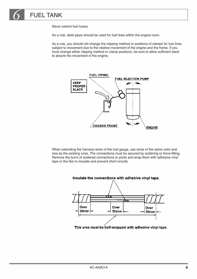
FUEL TANK6
KC-AA201A 4
Never extend fuel hoses.
As a rule, steel pipes should be used for fuel lines within the engine room.
As a rule, you should not change the clipping method or positions of clamps for fuel lines subject to movement due to the relative movement of the engine and the frame. If you must change either clipping method or clamp positions, be sure to allow sufficient slack to absorb the movement of the engine.
When extending the harness wires of the fuel gauge, use wires of the same color and size as the existing ones. The connections must be secured by soldering or force-fitting. Remove the burrs of soldered connections or joints and wrap them with adhesive vinyl tape or the like to insulate and prevent short circuits.
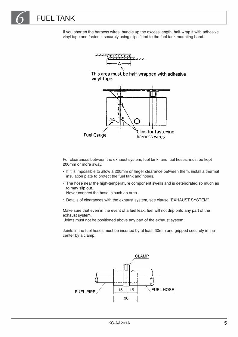
FUEL TANK6
KC-AA201A 5
If you shorten the harness wires, bundle up the excess length, half-wrap it with adhesive vinyl tape and fasten it securely using clips fitted to the fuel tank mounting band.
For clearances between the exhaust system, fuel tank, and fuel hoses, must be kept 200mm or more away.• If it is impossible to allow a 200mm or larger clearance between them, install a thermal
insulation plate to protect the fuel tank and hoses.• The hose near the high-temperature component swells and is deteriorated so much as
to may slip out. Never connect the hose in such an area.
• Details of clearances with the exhaust system, see clause “EXHAUST SYSTEM”.
Make sure that even in the event of a fuel leak, fuel will not drip onto any part of the exhaust system. Joints must not be positioned above any part of the exhaust system.
Joints in the fuel hoses must be inserted by at least 30mm and gripped securely in the center by a clamp.
CLAMP
FUEL HOSEFUEL PIPE 15 15
30

FUEL TANK6
KC-AA201A 6
Make sure that the filling port of the fuel tank is positioned at least 300mm away from the mouth of the exhaust tail pipe, and at least 200mm away from any exposed electrical terminals.
Make sure that the filling port of the fuel tank is positioned to allow easy filling and easy removal and replacement of the filler cap.
As a rule, the fuel tank must be mounted within the wheel base.
Secure the fuel hoses using clamps at 300 ~ 400mm intervals. Fuel hoses must not run next to electrical wiring and battery cables. Make sure that fuel hoses are positioned at least 30mm away from harness wires and battery cables.
Make sure that fuel hoses are positioned at least 10mm away from the corners of other parts, and at least 10mm away from the maximum range of movement of any parts subject to relative movement. Secure the hoses with clamps.
Fuel tank must be mountedwithin this range.
Fuel tank must not bemounted in this range.

FUEL TANK6
KC-AA201A 7
When using the vehicle’s main fuel tank to supply fuel to the engine of a refrigerator or other equipment, be sure that the fuel for this engine is taken directly from the main fuel tank. Never take a line from the main fuel feed system as this will interfere with the main engine fuel supply.
Install the relocated tank securely so that its bands do not become loose or the tank itself does not move due to vibrations caused while the vehicle is running.
When fabricating a new mounting bracket for the relocated or additional fuel tank, it must have a shape that can resist the vibrations and movements caused while the vehicle is running.
Make sure that the fuel tank must be relocated to the place where do not interfere with tire chain.

FUEL TANK6
KC-AA201A 8
2. MOVING THE FUEL TANK
When moving the fuel tank, observe the precautions described in Item 1, “PRECAUTIONS FOR RELOCATING THE FUEL TANK” and follow the procedure described below, and be sure to secure the tank firmly to prevent loosening of the mounting bands or slipping of the tank due to vibrations during driving.
Mounting the Fuel Tank in High Position
Make a bracket and mount the tank as shown in the drawing.
Mounting the Fuel Tank in Low Position
Make a bracket and mount the tank as shown in the drawing.

FUEL TANK6
KC-AA201A 9
3. MODIFICATION OR ADDITION FUEL TANK
When mounting an additional fuel tank, observe the precautions described in Item 1, “PRECAUTIONS FOR RELOCATING THE FUEL TANK” and follow the procedure described below, and be sure to secure the tank firmly to prevent loosening of the mounting bands or slipping of the tank due to vibrations during driving.
Fit a cut-off cock to the connecting pipe between the main tank and the additional sub-tank.
The main tank and the sub-tank must be mounted at the same height.
When welding the joint of the connecting pipe to the head plate of the tank, empty all fuel from the tank and fill the tank with water. Use the gas welding method.
Total capacity of the fuel tank must be less than 1,000liters for vehicle safety purpose.
77710-1080 Cock assy, fuel
Q'ty / Unit Parts No. Description
01
77204-2080 Pipe sub assy 02
9005-61670 Hose 01
77258-1380 Bracket 01
9005-61641 Hose 01
9659-14114 Washer,soft 02
L=2000mm Ruber Hose
Parts name
NOTE Should more detailed data or information regarding the
fuel tank be needed, please contact authorized Hino distributor or sales dealer.

FUEL TANK6
KC-AA201A 10
4. OTHER NOTES ON RELOCATING OR ADDING THE FUEL TANK
The original clearance between the fuel tank and the frame allows space for U-bolts used in body mounting. When moving the fuel tank or mounting an additional fuel tank, make sure that you allow space for these U-bolts.
When moving the fuel tank or mounting an additional fuel tank, make sure that it does not protrude beyond the overall width of the vehicle.
In vehicles for export from Japan, a pre-fuel filter and sedimenter are fitted to the frame along with the fuel tank to suit conditions of use When moving the fuel tank or mounting an additional fuel tank, make sure that you arrange the piping of these parts correctly
Fuel tanks must be mounted outside the locus of the bending radius of the fender to prevent them from interfering with the tire.
The original bracket for the fuel tank is designed to support the weight of the tank. Never mount body parts or side guard parts on the fuel tank bracket.
When moving the fuel tank or mounting an additional fuel tank, mount the bracket on the frame using bolts. Never use welding. (When making holes in the frame for mounting the bracket, see “DRILLING AND WELDING” under Section 2, “CHASSIS FRAME”)
Fit protectors to ensure that the vehicle's load does not come into contact with the fuel tank or any part of the piping.

KC-AA201A
Chapter 7ELECTRICAL SYSTEM
1. REAR LAMPS ••••••••••••••••••••••••••••••••••••••••••••••••••• 2 2. BACK-UP BUZZER ••••••••••••••••••••••••••••••••••••••••••••• 11 3. SPARE POWER TERMINALS •••••••••••••••••••••••••••••••• 12 4. HARNESS WIRING ••••••••••••••••••••••••••••••••••••••••••••• 29 5. GENERAL PRECAUTIONS FOR
ELECTRONIC EQUIPMENT ••••••••••••••••••••••••••••••• 39 6. ELECTRIC WIRE SIZE AND PERMISSIBLE
CURRENTS •••••••••••••••••••••••••••••••••••••••••••••••••••• 41

ELECTRICAL SYSTEM7
KC-AA201A 1
The chassis is usually shipped from the factory with brackets for the rear combination lamps and rear license plate temporarily fitted. At the time of mounting a body or equipment, make sure you observe the following precautions to fit the these electrical parts or other electrical component to the body or equipment.
Warning
Mounting an excessive number of lamps or taking-out electrical power for a body or equipment can damage the electrical systems and may lead to burnouts of the harness wires.
Therefore, in the event that you are obliged to carry out the body mounting exceeding the capacity of the alternator, consult your nearest Hino service dealer or distributor.

ELECTRICAL SYSTEM7
KC-AA201A 2
1. REAR LAMPS
The rear combination lamps, license plate lamp and reversing lamp are temporarily mounted on the chassis for shipment. At the time of mounting a body or equipment, use these parts as supplied and fit them in the positions shown in the drawing below. For details of fitting procedures for each lamp, see following pages.
NOTE All distances from ground and protrusions beyond maximum width
are the values prescribed by Japanese laws and regulations. When positioning lamps, make sure that you observe the laws and regulations of the country in which the vehicle is to be used.
MIN. 600mmDIRECTIONAL INDICATOR'SINNER EDGE SPACE
MAX. 400mm
MAX. 400mm
MAX. 400mm
REFLECTINGUPPER EDGE
REFLECTINGLOWER EDGE
LIGHTING UPPER EDGE
LIGHTING LOWER EDGE
REAR & STOP LAMP
REAR REFLECTOR
DIRECTIONALINDICATOR& HAZARD LAMP
BACK-UP LAMP
LICENSE PLATE LAMP
GR
OU
ND
HE
IGH
T M
IN.0
.25m
MAXIMUM OVERALL WIDTHG
RO
UN
D H
EIG
HT
MA
X.0
.9m
GR
OU
ND
HE
IGH
T M
IN.0
.35m
GR
OU
ND
HE
IGH
T M
AX
.1.5
m
STOP LAMP (WITHOUT IN THE CASE OF DUAL TYPE REAR LAMP)

ELECTRICAL SYSTEM7
KC-AA201A 3
Rear Combination Lamp
Install the lamps symmetry on right and left except license plate lamp.
Install the lamp that drainage hole is always to be bottom side.
The drainage hole in the bottom of the lamp is covered with tape for shipment. After installing the lamps, be sure to remove the tape.
Don’t install any parts of body or equipment to rearward of the rear combination lamp to insure the visibility of lamp.
Install the water guard plate in order to prevent direct exposure to water splashed up from rear wheels.
Make sure that the lamp lenses and bodies do not come into contact with clear anti-rust coating.
To prevent the lamp from shaking, always use a strengthening stay such as dump truck in which lamps couldn’t be installed direct to the body (vessel).

ELECTRICAL SYSTEM7
KC-AA201A 4
EXTERNAL ASPECT OF REAR COMBINATION LAMP (FOR REFERENCE)
Dimensions and shape are shown in the drawing below.
[STANDARD DUAL LAMP TYPE] (Drawing shows right-hand lamp only. Positions reversed for left lamp.)
NOTE• For the exact rear combination lamp to be installed to the each vehicle,
refer to Body Mounting Manual for the respective model series.
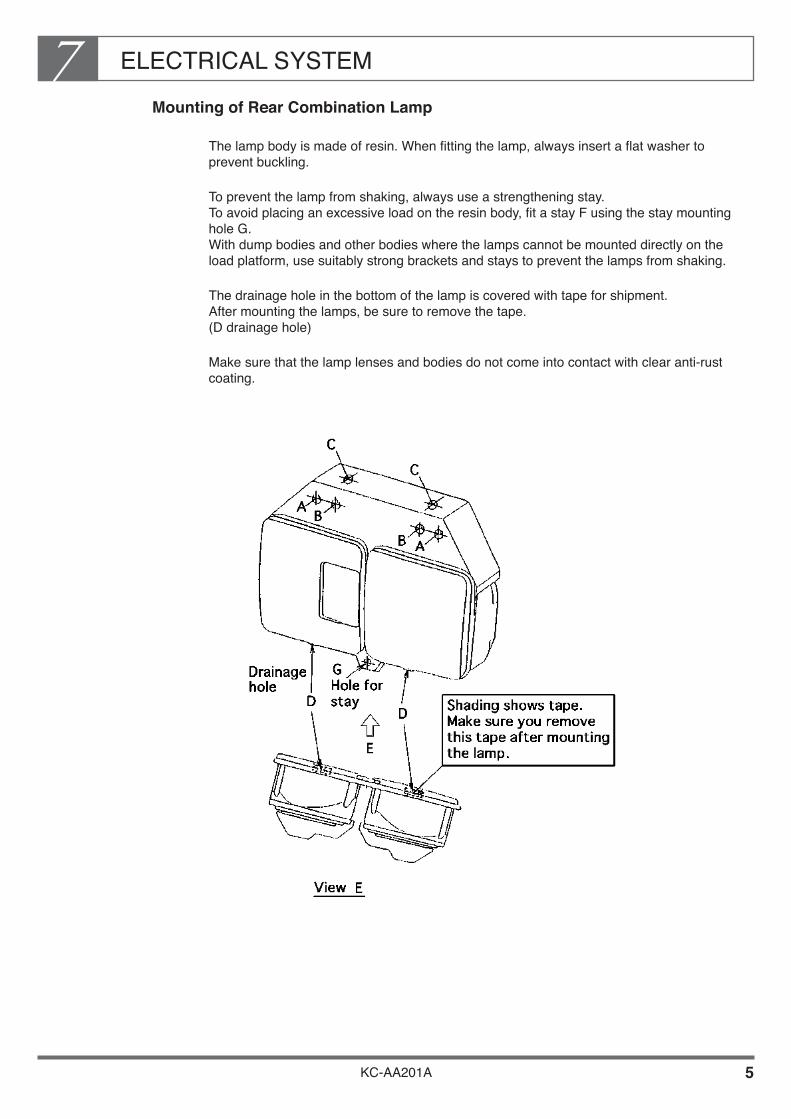
ELECTRICAL SYSTEM7
KC-AA201A 5
Mounting of Rear Combination Lamp
The lamp body is made of resin. When fitting the lamp, always insert a flat washer to prevent buckling.
To prevent the lamp from shaking, always use a strengthening stay. To avoid placing an excessive load on the resin body, fit a stay F using the stay mounting hole G. With dump bodies and other bodies where the lamps cannot be mounted directly on the load platform, use suitably strong brackets and stays to prevent the lamps from shaking.
The drainage hole in the bottom of the lamp is covered with tape for shipment. After mounting the lamps, be sure to remove the tape. (D drainage hole)
Make sure that the lamp lenses and bodies do not come into contact with clear anti-rust coating.

ELECTRICAL SYSTEM7
KC-AA201A 6
Details of temporary mounting for shipment
The lamps are temporarily mounted on the rear end of the chassis using mounting hole C.
Notes on final mounting
Steel mounting bracket Wooden mounting bracket
Fitting a stay
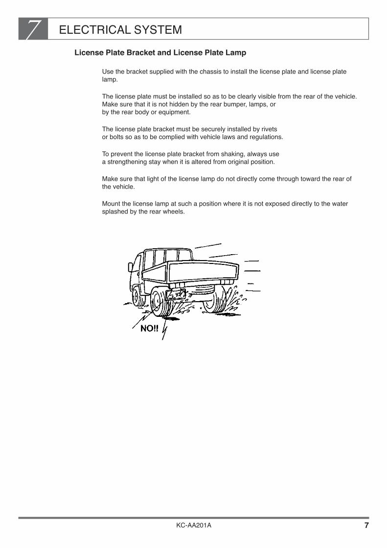
ELECTRICAL SYSTEM7
KC-AA201A 7
License Plate Bracket and License Plate Lamp
Use the bracket supplied with the chassis to install the license plate and license plate lamp.
The license plate must be installed so as to be clearly visible from the rear of the vehicle. Make sure that it is not hidden by the rear bumper, lamps, or by the rear body or equipment.
The license plate bracket must be securely installed by rivets or bolts so as to be complied with vehicle laws and regulations.
To prevent the license plate bracket from shaking, always use a strengthening stay when it is altered from original position.
Make sure that light of the license lamp do not directly come through toward the rear of the vehicle.
Mount the license lamp at such a position where it is not exposed directly to the water splashed by the rear wheels.
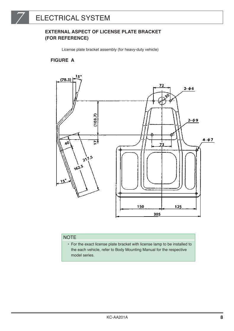
ELECTRICAL SYSTEM7
KC-AA201A 8
EXTERNAL ASPECT OF LICENSE PLATE BRACKET (FOR REFERENCE)
License plate bracket assembly (for heavy-duty vehicle)
FIGURE A
NOTE• For the exact license plate bracket with license lamp to be installed to
the each vehicle, refer to Body Mounting Manual for the respective model series.
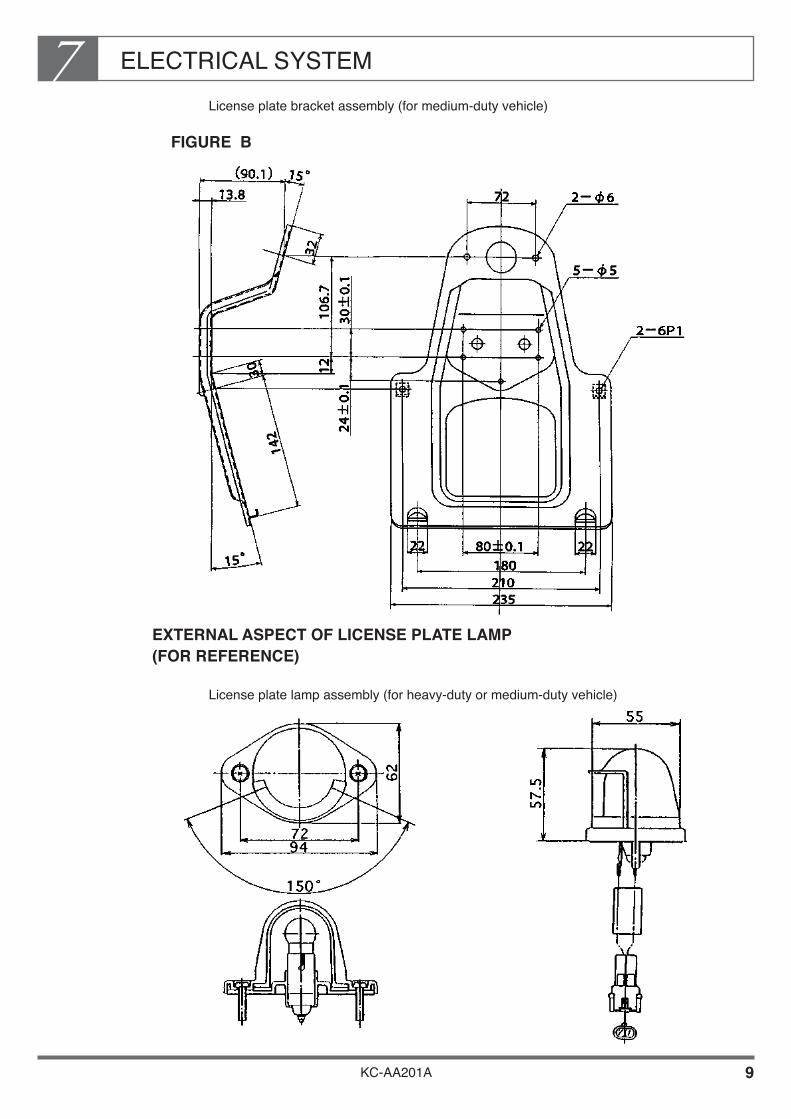
ELECTRICAL SYSTEM7
KC-AA201A 9
License plate bracket assembly (for medium-duty vehicle)
FIGURE B
EXTERNAL ASPECT OF LICENSE PLATE LAMP (FOR REFERENCE)
License plate lamp assembly (for heavy-duty or medium-duty vehicle)

ELECTRICAL SYSTEM7
KC-AA201A 10
Back-up Lamp
If possible, use the back-up lamp as mounted on the chassis at time of shipment. If you must move this lamp, be sure to mount it at oriented so that the main beam points downwards and be sure to mount the lamp so that the beam reaches the ground within 75 m from the rear of the vehicle.
Back-up lamp assembly (For reference)
NOTE• For the exact back-up lamp to be installed to the each vehicle, refer to
Body Mounting Manual for the respective model series.
• Make sure that the lighting distance of the back-up lamp must be complied with vehicle laws and regulations in the each country where vehicle is to be operated.
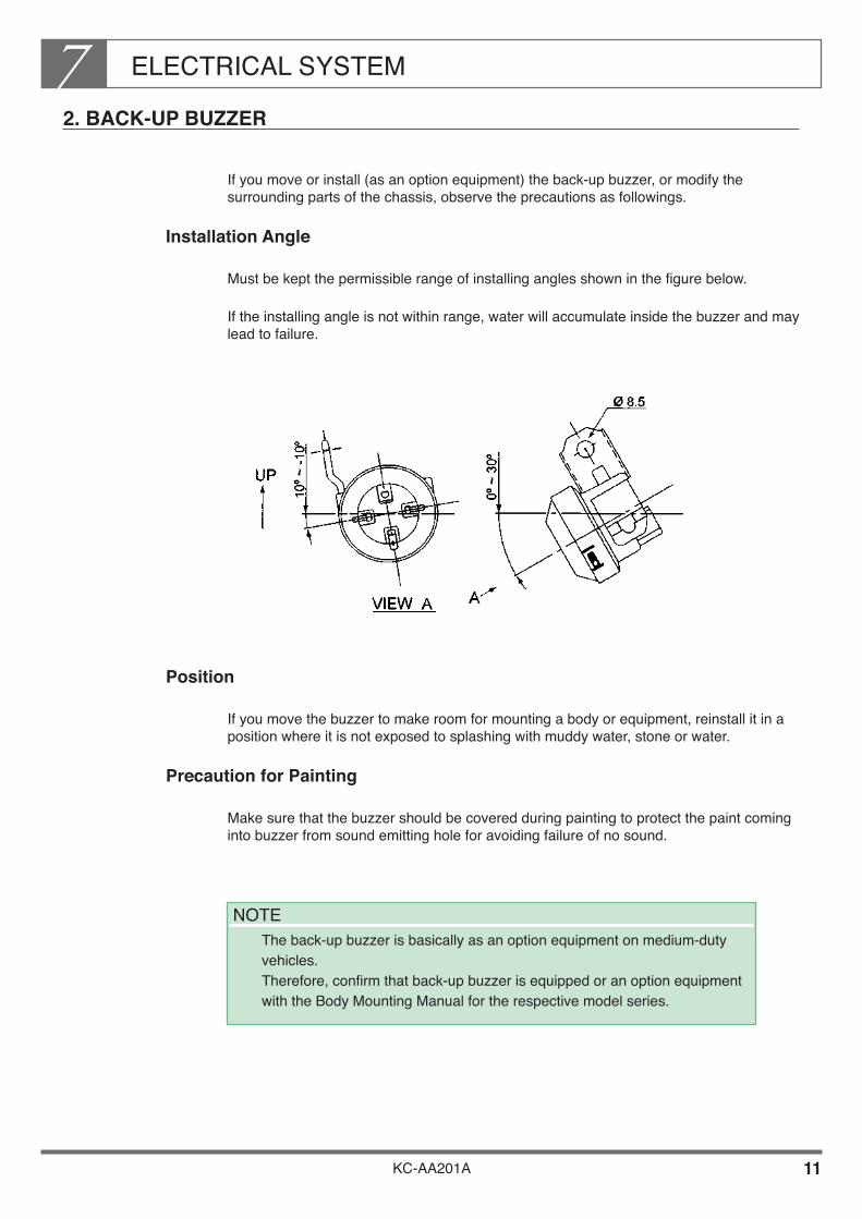
ELECTRICAL SYSTEM7
KC-AA201A 11
2. BACK-UP BUZZER
If you move or install (as an option equipment) the back-up buzzer, or modify the surrounding parts of the chassis, observe the precautions as followings.
Installation Angle
Must be kept the permissible range of installing angles shown in the figure below.
If the installing angle is not within range, water will accumulate inside the buzzer and may lead to failure.
Position
If you move the buzzer to make room for mounting a body or equipment, reinstall it in a position where it is not exposed to splashing with muddy water, stone or water.
Precaution for Painting
Make sure that the buzzer should be covered during painting to protect the paint coming into buzzer from sound emitting hole for avoiding failure of no sound.
NOTE The back-up buzzer is basically as an option equipment on medium-duty
vehicles. Therefore, confirm that back-up buzzer is equipped or an option equipment with the Body Mounting Manual for the respective model series.

ELECTRICAL SYSTEM7
KC-AA201A 12
3. SPARE POWER TERMINALS
If you must take an electrical power supply for the body or equipment from the chassis, take it from the spare power supply.
For the Heavy-duty Vehicles
Spare power supply terminals and positions
A spare power supply is fitted to the harness wires. There are four types of spare power terminals as shown in the table below.
Outlet Positions on Chassis
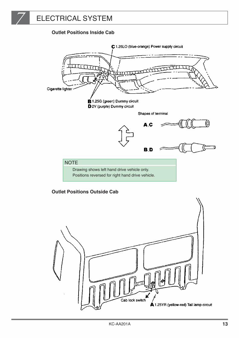
ELECTRICAL SYSTEM7
KC-AA201A 13
Outlet Positions Inside Cab
Outlet Positions Outside Cab
NOTE Drawing shows left hand drive vehicle only.
Positions reversed for right hand drive vehicle.

KC-AA201A 14
ELECTRICAL SYSTEM7Electric Wiring of Spare Outlets

ELECTRICAL SYSTEM7
KC-AA201A 15
Fuse Block and Relay Panel
[Location] The fuse block and the relay panel are located inside of the instrument panel as shown below. (Drawing shows left hand drive vehicle only. Positions reversed for right hand drive vehicle.)

ELECTRICAL SYSTEM7
KC-AA201A 16
[Fuse Block]
NOTE• Be sure to use each capacity fuse designated in the above table.
• Never use the capacity fuse exceeding the designated one in the above, otherwise over current may damage the harness wires, and fusible linkage wires are in the same.
• For the details of fuse block, refer to the Body Mounting Manual for the respective model series.

ELECTRICAL SYSTEM7
KC-AA201A 17
[Relay Panel]
1 16
NoNo
HEAD LAMP RELAY ( MAIN )
2 FLASHER UNIT RELAY
DESCRIPTION DESCRIPTION
17 HORN RELAY
3 POWER RELAY NO.1 18
4 19 INTERMITTENT WIPER RELAY
5 20
6 TAIL LAMP RELAY NO.2 21
7 TAIL LAMP RELAY NO.1 22 CIRCUIT BREAKER
8 POWER RELAY NO.2 23
----------
----------
----------
----------
----------
----------
----------
9 24
10 25
11 26
12 27
13 POWER RELAY NO.3 28
14
15 HEAD LAMP RELAY ( DIMMER )
----------29
STOP LAMP RELAY
ONE-KEY STOP RELAY
----------
----------
----------
----------
----------
WHEEL PARKING RELAY
SUB-STARTER RELAY
TRANSMISSION LOW/HIGH SHIFT RELAY
NOTE For the detail of installed relays, refer to the Body Mounting Manual
for the respective model series.
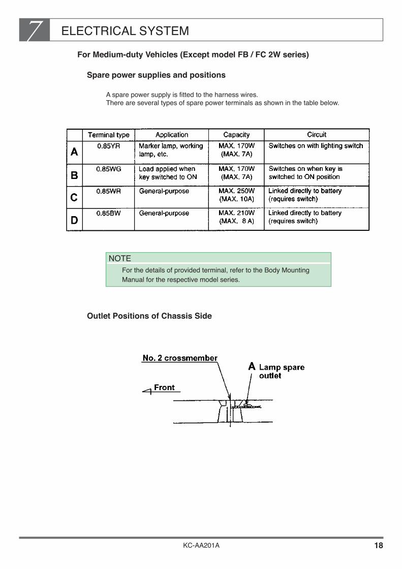
ELECTRICAL SYSTEM7
KC-AA201A 18
For Medium-duty Vehicles (Except model FB / FC 2W series)
Spare power supplies and positions
A spare power supply is fitted to the harness wires. There are several types of spare power terminals as shown in the table below.
Outlet Positions of Chassis Side
NOTE For the details of provided terminal, refer to the Body Mounting
Manual for the respective model series.
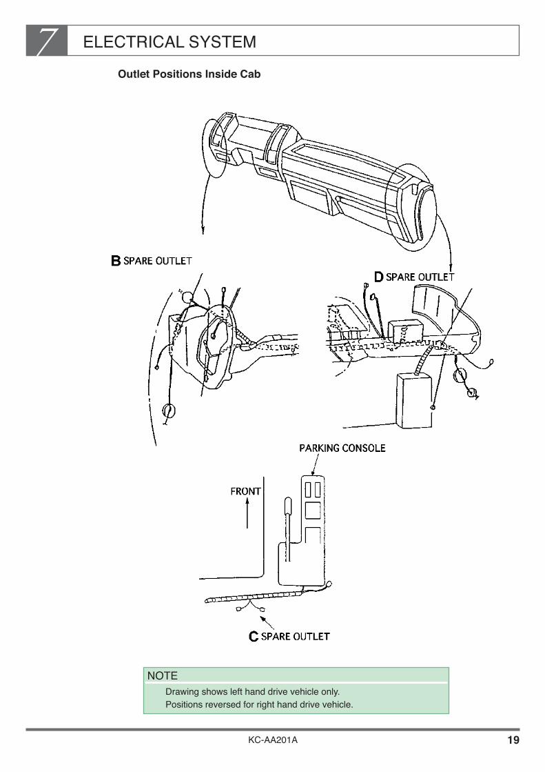
ELECTRICAL SYSTEM7
KC-AA201A 19
Outlet Positions Inside Cab
NOTE Drawing shows left hand drive vehicle only.
Positions reversed for right hand drive vehicle.

KC-AA201A 20
ELECTRICAL SYSTEM7Electric Wiring of Spare Outlet
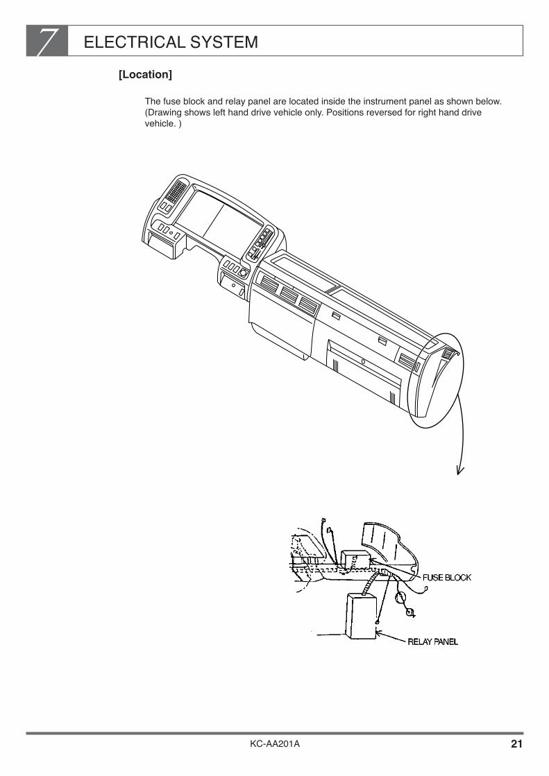
ELECTRICAL SYSTEM7
KC-AA201A 21
[Location]
The fuse block and relay panel are located inside the instrument panel as shown below. (Drawing shows left hand drive vehicle only. Positions reversed for right hand drive vehicle. )
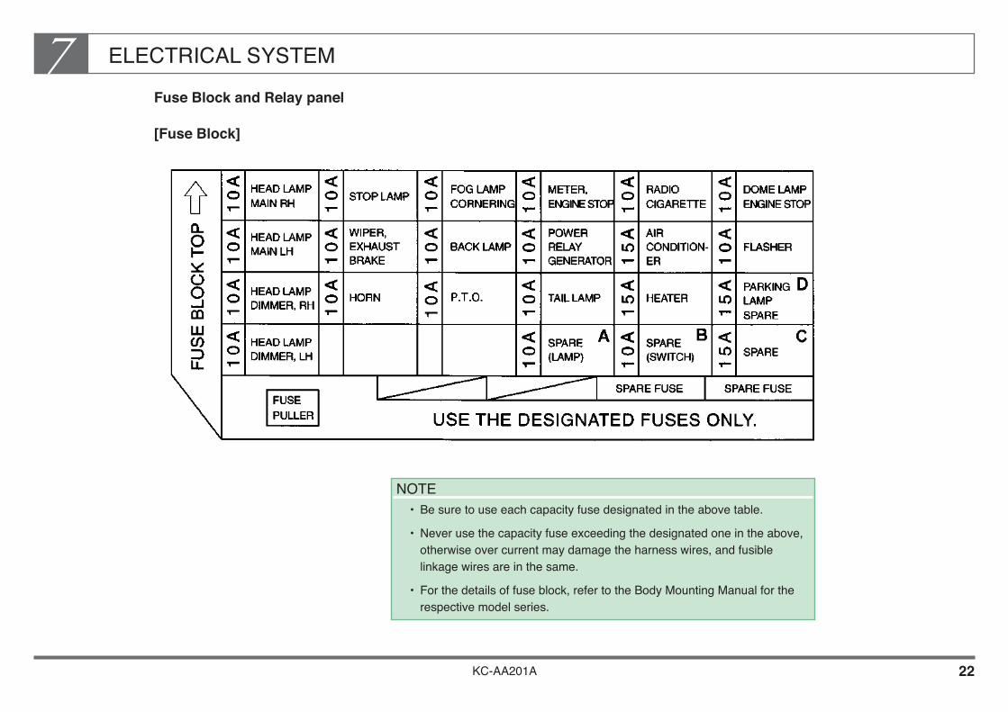
KC-AA201A 22
ELECTRICAL SYSTEM7Fuse Block and Relay panel
[Fuse Block]
NOTE• Be sure to use each capacity fuse designated in the above table.
• Never use the capacity fuse exceeding the designated one in the above, otherwise over current may damage the harness wires, and fusible linkage wires are in the same.
• For the details of fuse block, refer to the Body Mounting Manual for the respective model series.

ELECTRICAL SYSTEM7
KC-AA201A 23
[Relay Panel]
NOTE For the delail of installed relays, refer to the Body Mounting Manual
for the respective model series.
No.POLE NUMBER
OF CONNECTORDESCRIPTION No.
POLE NUMBEROF CONNECTOR
DESCRIPTION
2
– –
– –
– –
– –
– –
– –
– –
4 POWER RELAY NO.2
4 FOG LAMP RELAY 6 STOP LAMP RELAY
4HEAD LAMP RELAY
(DIMMER)4
4HEAD LAMP RELAY
(MAIN)4 POWER RELAY NO.3
6 ONE-KEY STOP RELAY 2
4 TAI L LAMP RELAY 4
4 POWER RELAY NO.1 13INTERMITTENTWIPER RELAY
6 2
4 HORN RELAY 6
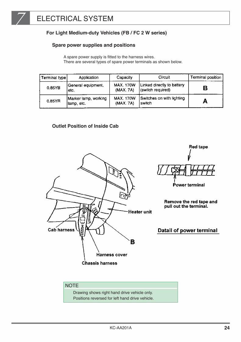
ELECTRICAL SYSTEM7
KC-AA201A 24
For Light Medium-duty Vehicles (FB / FC 2 W series)
Spare power supplies and positions
A spare power supply is fitted to the harness wires. There are several types of spare power terminals as shown below.
Outlet Position of Inside Cab
NOTE Drawing shows right hand drive vehicle only.
Positions reversed for left hand drive vehicle.
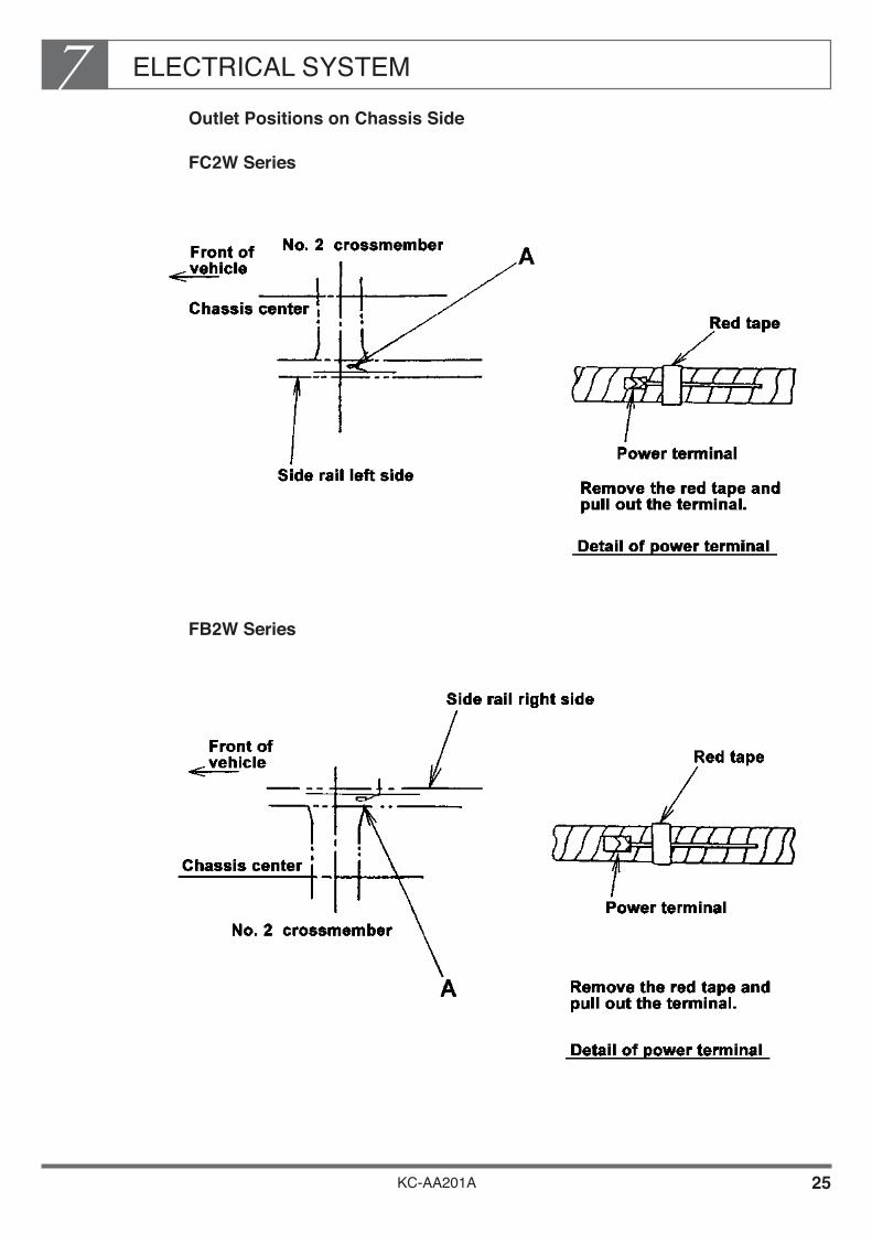
ELECTRICAL SYSTEM7
KC-AA201A 25
Outlet Positions on Chassis Side
FC2W Series
FB2W Series

KC-AA201A 26
ELECTRICAL SYSTEM7Electric Wiring of Spare Outlet
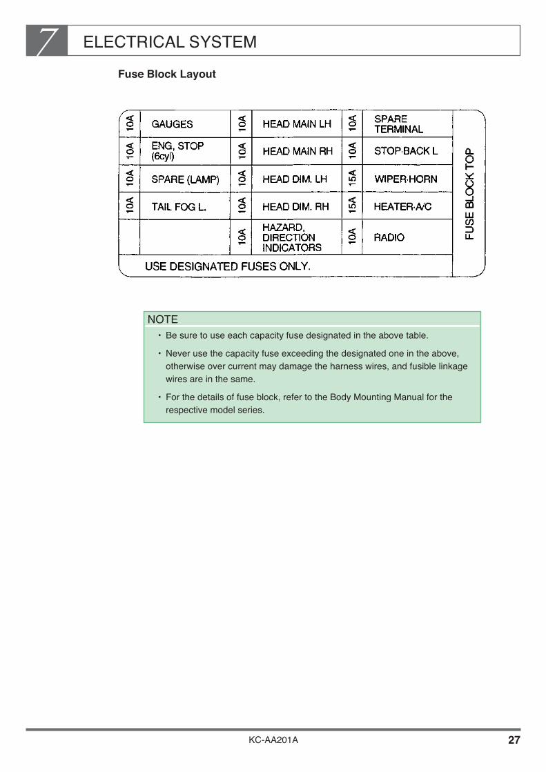
ELECTRICAL SYSTEM7
KC-AA201A 27
Fuse Block Layout
NOTE• Be sure to use each capacity fuse designated in the above table.
• Never use the capacity fuse exceeding the designated one in the above, otherwise over current may damage the harness wires, and fusible linkage wires are in the same.
• For the details of fuse block, refer to the Body Mounting Manual for the respective model series.

ELECTRICAL SYSTEM7
KC-AA201A 28
Taking Power Directly from the Battery
If you intend to take power for the body directly from the battery, secure the battery cable and the body power supply terminal together with the same nut. (See drawing.) In this case, you must install a fuse at a suitable point in the circuit and take precautions to prevent short circuits as these may lead vehicle fires. When securing the cable and power terminal, make sure you tighten the nut properly.

ELECTRICAL SYSTEM7
KC-AA201A 29
4. HARNESS WIRING
If a mistake is made in the harness wiring while mounting a body or equipment, the harness may be damaged by vehicle vibration while the vehicle is driving, or water, dust, or mud entering into the harness. If these occur, a short-circuit or fire may result causing a severe accident.
Accordingly, be sure to observe the procedures given below for modifications or alterations of the harness wiring involved with the body mounting or other actions.
Precautions when Mounting Body or Equipment
When installing U-bolts or body mounting brackets, observe the following precautions.• Make sure that harness wires and battery cables are not squeezed or pinched, and do
not come into contact with sharp edges or corners.
• Make sure that harness wires, battery cables and other electric equipment (switches, battery, etc.) are easily accessible for maintenance.
If you fit additional switches or lamps for a body or equipment, observe the following precautions.• To prevent accidental operation or confirmation, install a caution plate showing the
purpose of each switch, etc.

ELECTRICAL SYSTEM7
KC-AA201A 30
• Common use of switches which are already installed on the chassis side for control of lamps installed on the body side or other electrical equipment is prohibited. An overload will occur resulting in burning of the switch contacts or harness. The control of the electrical equipment on the body side should be done using a separately installed switch.
If you intended to fit a buzzer for a body or equipment, make sure that its sound is clearly different from that of the existing buzzer around the driver’s seat of chassis.
[SPECIFICATION OF EXISTING BUZZER AROUND DRIVER’S SEAT]
Do not force to pull the harness wiring when handle it.
When removing the connector, be sure to hold the male and female parts of the connector by housing. Do not remove the connector by holding harness wire.

ELECTRICAL SYSTEM7
KC-AA201A 31
Secure an adequate clearance with the high-temperature parts. Measure the temperature whenever required to eliminate the safety problems.• Don’t lay the wiring in the vicinity of the exhaust pipe or muffler or where the wiring is
exposed directly to the exhaust gas. (Clearance between exhaust system and harness wiring; Minimum 200mm)
Addition or Modification of wiring
If you intend to extend wiring, make sure that you use the same size and color of wire as the original.
Make all connections secure by soldering or pressure joints. After connecting, remove burrs and cover fully with insulation material. When making connections in chassis side wiring, cover connections with waterproof sealant, then cover fully with insulating material.
[EXAMPLE FOR WATERPROOFING AND INSULATION]
Cover connections with adhesive heat contraction tube.
Cover connections with butyl rubber.

ELECTRICAL SYSTEM7
KC-AA201A 32
When soldering, do not use chlorine.
If you intend to move the battery or modify the battery cable layout, do not extend or shorten the battery cable. In areas where the battery cables are subject to movement due to relative motion of the starter and the frame, do not modify the clamping method, positions of clamps, or the amount of slack in the cables.
Clamp electric wiring firmly to prevent it from contacting the moving or vibrating parts of the chassis or body, and any sharp edges or corners.
[CLEARANCES FOR WIRE]
Where wiring passes through the frame or a panel, always use a grommet to prevent damage to the wire and potential short circuits.
EXAMPLE OF USING GROMMET
Protection of harness which penetrates frame and panel
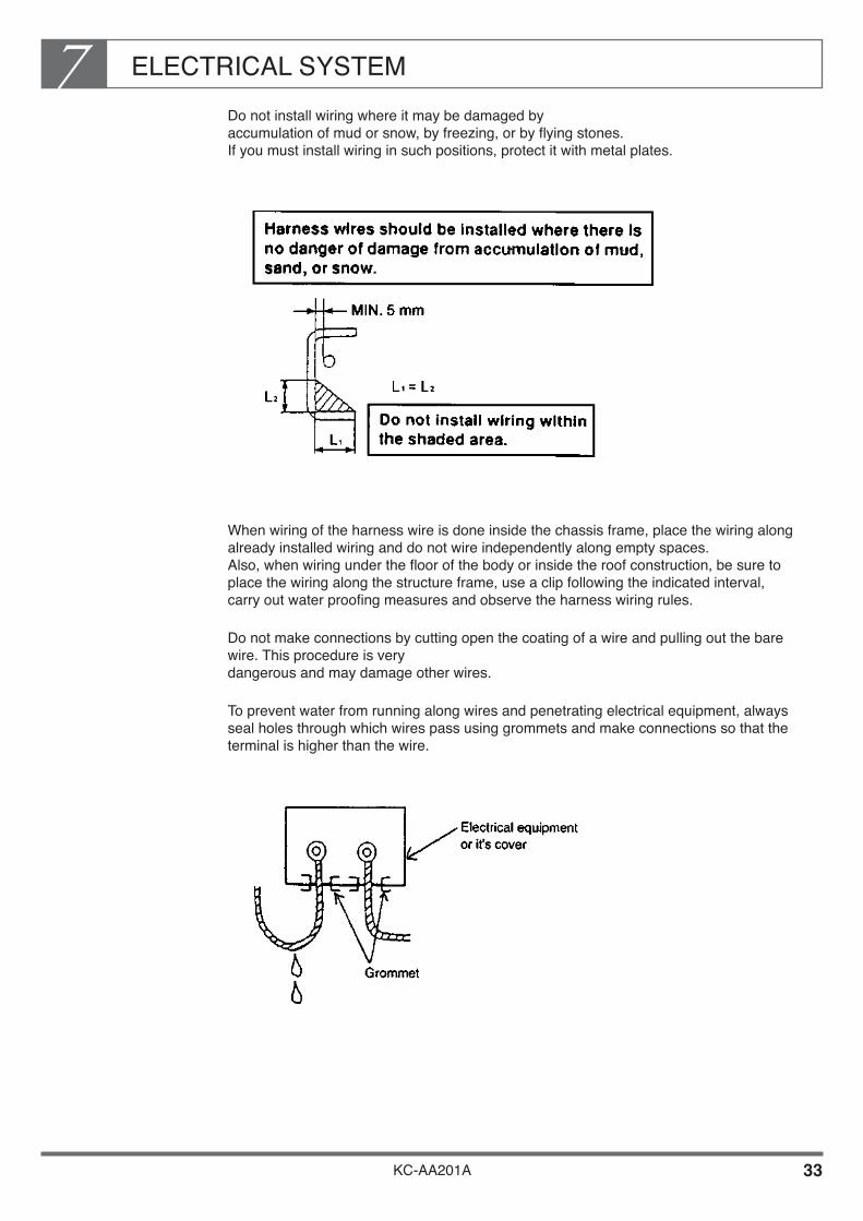
ELECTRICAL SYSTEM7
KC-AA201A 33
Do not install wiring where it may be damaged by accumulation of mud or snow, by freezing, or by flying stones. If you must install wiring in such positions, protect it with metal plates.
When wiring of the harness wire is done inside the chassis frame, place the wiring along already installed wiring and do not wire independently along empty spaces. Also, when wiring under the floor of the body or inside the roof construction, be sure to place the wiring along the structure frame, use a clip following the indicated interval, carry out water proofing measures and observe the harness wiring rules.
Do not make connections by cutting open the coating of a wire and pulling out the bare wire. This procedure is very dangerous and may damage other wires.
To prevent water from running along wires and penetrating electrical equipment, always seal holes through which wires pass using grommets and make connections so that the terminal is higher than the wire.

ELECTRICAL SYSTEM7
KC-AA201A 34
Install wires where they are not exposed to dust or water.
Do not install the harness wire on the top or outer side of the chassis frame. In such positions, they may be damaged by being stepped on during body mounting, or by flying stones during vehicle operation.
If there is a harness for the chassis already installed close to the wiring area when wiring is done inside the chassis frame, the wiring and taping should be done along this harness.
When installing wiring for parts of the engine, transmission, etc., install the wiring in parallel to existing wires, and be sure to allow sufficient slack to adsorb any relative movement. Make sure that the wiring does not touch any other part.
Where electrical wiring runs parallel to pipes (including rubber hoses, vinyl hoses, and steel pipes) or brake system pipes (including brake hoses and brake pipes), never clamp the wiring together with these pipes.
[CLEARANCES BETWEEN HARNESS WIRES AND PIPES]

ELECTRICAL SYSTEM7
KC-AA201A 35
If you move the battery, you may have to temporarily remove the battery cables from the terminals of the battery. When refitting the battery cables, observe the specified torque to avoid damaging the battery terminal: Tightening torque : 9.8~15.7 N•m {100~160 kgf•cm} (If a terminal is damaged, replace it with a new part.)
If you move the battery, make sure it is positioned at least 200 mm away from the exhaust system (muffler, tail pipe, etc.). If you must install the battery within 200 mm of the exhaust system, protect it with insulating panels.
Always use a connector with lock.
If you use a plug-type connecting terminal, fit the female terminal into the power supply side. This is due to the connecting terminal detaching which does not allow a short-circuit to occur even if the chassis or body construction make contact.
To prevent sagging, contact with other parts or contact with sharp edges or corners, secure all wiring with clips.
The clips should be spaced at a standard interval of 300~500 mm. This interval should be shorter where conditions dictate.
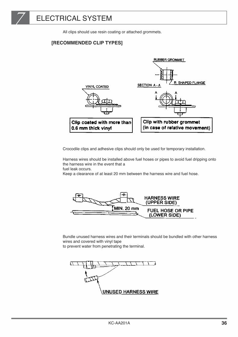
ELECTRICAL SYSTEM7
KC-AA201A 36
All clips should use resin coating or attached grommets.
[RECOMMENDED CLIP TYPES]
Crocodile clips and adhesive clips should only be used for temporary installation.
Harness wires should be installed above fuel hoses or pipes to avoid fuel dripping onto the harness wire in the event that a fuel leak occurs. Keep a clearance of at least 20 mm between the harness wire and fuel hose.
Bundle unused harness wires and their terminals should be bundled with other harness wires and covered with vinyl tape to prevent water from penetrating the terminal.
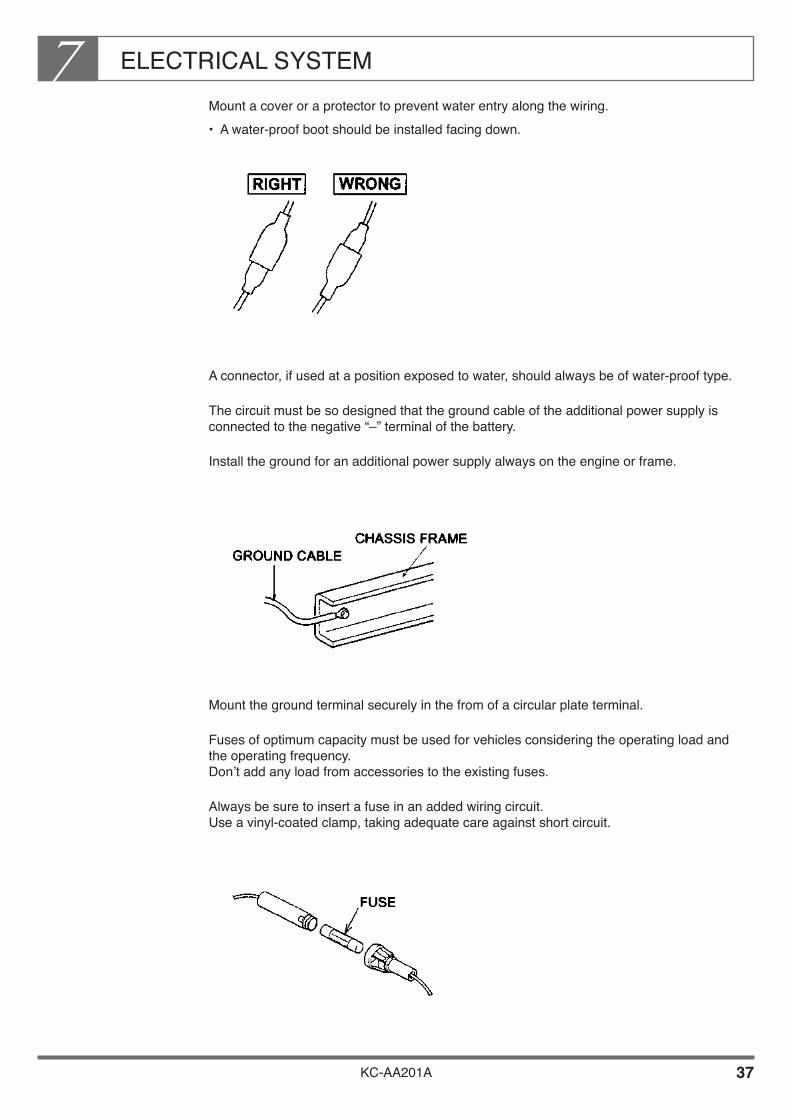
ELECTRICAL SYSTEM7
KC-AA201A 37
Mount a cover or a protector to prevent water entry along the wiring.• A water-proof boot should be installed facing down.
A connector, if used at a position exposed to water, should always be of water-proof type.
The circuit must be so designed that the ground cable of the additional power supply is connected to the negative “–” terminal of the battery.
Install the ground for an additional power supply always on the engine or frame.
Mount the ground terminal securely in the from of a circular plate terminal.
Fuses of optimum capacity must be used for vehicles considering the operating load and the operating frequency. Don’t add any load from accessories to the existing fuses.
Always be sure to insert a fuse in an added wiring circuit. Use a vinyl-coated clamp, taking adequate care against short circuit.

ELECTRICAL SYSTEM7
KC-AA201A 38
• The fuse capacity should be about 1.4 times the load current. Ex : For the load current of 3A, 3 x 1.4 = 4.2 A Therefore, the standard fuse capacity of 5A is the best choice.
FUSE RATED CURRENT AGAINST LOAD (Automobile Standard JASO D610-75)
Ex : 5A fuse can be used for the load current of 3.5A maximum.
When installing additional electronic machine, the circuit must be wired through the fusible link and to be grounded direct to the frame.• Be sure not to flow the dormant current in the circuit.
Make sure that the clamp of the harness wire should be added to install as occasion demands to prevent the resonance oscillation of the harness wiring due to engine vibration and vehicle’s running.• Take special attention for the clamping that the case to be used harness wiring with
fusible link.
When installing electric motor consumed bigger load, be sure to use the appropriate size of harness wire.• If over capacity of spare power circuit, take the power direct from the battery.
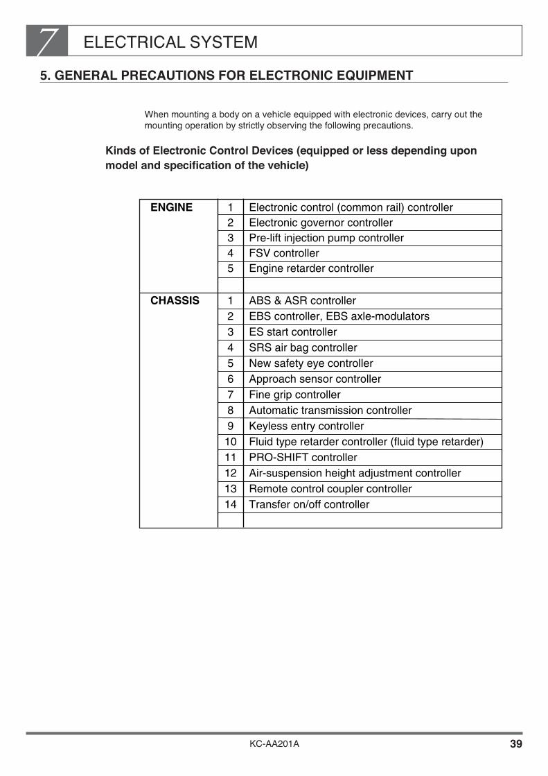
ELECTRICAL SYSTEM7
KC-AA201A 39
5. GENERAL PRECAUTIONS FOR ELECTRONIC EQUIPMENT
When mounting a body on a vehicle equipped with electronic devices, carry out the mounting operation by strictly observing the following precautions.
Kinds of Electronic Control Devices (equipped or less depending upon model and specification of the vehicle)
ENGINE Electronic control (common rail) controller1
CHASSIS ABS & ASR controller1EBS controller, EBS axle-modulators2ES start controller3SRS air bag controller4New safety eye controller5Approach sensor controller6Fine grip controller7Automatic transmission controller8Keyless entry controller9Fluid type retarder controller (fluid type retarder)10PRO-SHIFT controller11Air-suspension height adjustment controller12Remote control coupler controller13Transfer on/off controller14
Electronic governor controller2Pre-lift injection pump controller3FSV controller4Engine retarder controller5

ELECTRICAL SYSTEM7
KC-AA201A 40
Precautions to take when handling electronic parts
As minute electric current flows through electronic control circuits (such as control units, actuators, sensors, etc.), special multi-pole connectors are used on the circuits. Therefore, pay attention to the following points:• Do not remove or engage connectors unnecessarily.
Otherwise, it will result in a poor contact due to lowering of engaging force caused by deformation or damage of the terminals.
• When removing a connector, be sure to carry out this operation by holding a male and a female connector housing. Never attempt to remove it by pulling the cables or kneading them. Otherwise, it will lead to damage of cables or deformation of terminals.
• Pay attention in such a way that water, oil or dust will not stick to the removed connectors. Sticking of such matters may causing a poor contact or instable conductivity.
• Connect the removed connector until it is securely locked.• Precautions to take concerning electronic control devices to be mounted.
Big noises generated by devices may provoke sometimes a wrong functioning of the electronic devices. Use such noise killing components as diodes, varistor (variable resistor) etc., on relays, solenoids, motors, etc. that are to be fitted additionally.

ELECTRICAL SYSTEM7
KC-AA201A 41
6. ELECTRIC WIRE SIZE AND PERMISSIBLE CURRENTS
Wire Size and Currents
When wiring the harness wire together with the body mounting operations, select an appropriate type of wire harness taking into consideration the power consumption capacity (A) of the electrical equipment such will be mounted and the condition of the installation location referring as following table.
WIRE TYPE
WIRE TYPE
WIRE SIZE AND LENGTH
WIRE SIZE AND PERMISSIBLE CURRENT
( A )
CONNECTINGFUSE CAPACITY AMBIENT
TEMPERATURE 0.5mm 0.85mm 1.25mm 2mm 3mm 5mm 8mmAV MAX. 80°C
MAX. 80°C
MAX. 80°C
MAX. 80°C
MAX. 80°C
MAX. 80°C
MAX. 80°C
MAX. 80°C
MAX. 80°C
MAX. 80°C
5 AVX MAX. 100°C
MAX. 100°C
MAX. 100°C
MAX. 100°C
MAX. 100°C
MAX. 100°C
MAX. 100°C
MAX. 100°C
MAX. 100°C
MAX. 100°C
MAX. 30m — — — — — —AEX MAX. 120°C
MAX. 120°C
MAX. 120°C
MAX. 120°C
MAX. 120°C
MAX. 120°C
MAX. 120°C
MAX. 120°C
MAX. 120°C
MAX. 120°C
AV10 AVX MAX. 15m MAX. 20m MAX. 30m — — — —
AEXAV
15 AVX X MAX. 15m MAX. 20m MAX. 35m — — —AEXAV
20 AVX X X MAX. 15m MAX. 25m MAX. 40m — —AEXAV
30 AVX X X X MAX. 5m MAX. 10m MAX. 15m MAX. 25mAEXAV
40 AVX X X X MAX. 5m MAX. 9m MAX. 20m MAX. 20mAEXAV
50 AVX X X X X MAX. 7m MAX. 10m MAX. 15mAEXAV
60 AVX X X X X X MAX. 5m MAX. 10mAEXAV
80 AVX X X X X X X MAX. 10mAEX
AV 9A 11A 14A 20A 27A 36A 47AAVX 8A 10A 13A 17A 24A 33A 43AAEX 7A 9A 12A 17A 23A 32A 42A
2 2 2 2 2 2 2
AMBIENTTEMPERATURE 0.5mm 0.85mm 1.25mm 2mm 3mm 5mm 8mm2 2 2 2 2 2 2

ELECTRICAL SYSTEM7
KC-AA201A 42
NOTE• Select wires size to suit the power consumption current.
• If you intend to use AEX wire, make sure that you also use heat resistant protective tubing, tape, and clips.
• Where the wire is subject to movement caused by relative motion, use wire of 0.85 mm2 cross section or larger.
• Characteristic of wire.
• Marked “x” can not be used. Marked “—” shows the wire length maximum 50 m.

ELECTRICAL SYSTEM7
KC-AA201A 43
Coding for Electrical Wires
Wire codes represent size and color

KC-AA201A
Chapter 8EXHAUST SYSTEM
1. PRECAUTIONS FOR MOUNTING A BODY OR EQUIPMENT •••••••••••••••••••••••••••••••••••••••••••••••••• 2
2. MODIFYING THE EXHAUST SYSTEM ••••••••••••••••••••• 4

EXHAUST SYSTEM8
KC-AA201A 1
The exhaust system becomes very hot during driving. When mounting a body or equipment, observe the following procedures to prevent vehicle fires.
Modifying the exhaust system has a major effect on vehicle performance and external noise. As a rule, the exhaust system must not be modified.
In some countries, external noise control regulations prohibit any modification of the exhaust system.
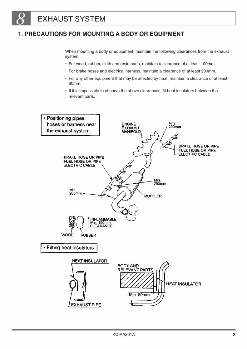
EXHAUST SYSTEM8
KC-AA201A 2
1. PRECAUTIONS FOR MOUNTING A BODY OR EQUIPMENT
When mounting a body or equipment, maintain the following clearances from the exhaust system.• For wood, rubber, cloth and resin parts, maintain a clearance of at least 100mm.• For brake hoses and electrical harness, maintain a clearance of at least 200mm.• For any other equipment that may be affected by heat, maintain a clearance of at least
80mm.• If it is impossible to observe the above clearances, fit heat insulators between the
relevant parts.

EXHAUST SYSTEM8
KC-AA201A 3
When installing a equipment (tool box, etc.) or inflammable object behind the outlet of the tail pipe, avoid the hatched area shown below.
Do not install the rope hook near the high-temperature area, or the rope or canvas could droop or touch the exhaust system. Install an insulation plate as necessary.
Install equipment in such a manner that the exhaust system is not exposed to the hydraulic fluid that may leak from the equipment.

EXHAUST SYSTEM8
KC-AA201A 4
2. MODIFYING THE EXHAUST SYSTEM
Modifying the exhaust system has a major effect on vehicle performance and external noise. As a rule, the exhaust system must not be modified. In some countries, external noise control regulations prohibit any modification of the exhaust system.
Do not modify any part within the range shown in the drawing below.
If you must modify the tail pipe in order to install a fire arrester, observe the following procedure:
The diameter and material of the pipe must be the same as those of the vehicle’s original pipe. The material used differ according to the type of vehicle;• Machine structural carbon steel pipe Color : Black• Zinc-plated steel pipe Color : Silver• Aluminum-plated steel pipe Color : Silver
The plating of zinc or aluminum-plated pipe will peel if the pipe is welded, and the rust-resistance of the pipe will deteriorate. After welding, paint the pipe in a similar color.
Extending or bending the tail pipe raises the exhaust resistance and will lead to a decline in engine output, an increase in fuel consumption, and an increase in exhaust gas density. Study the likely effects with care before making any modification of this kind. As a rule, the bending radius of the tail pipe should be at least 1.5 times the diameter of the pipe.
Do not modify any part of exhaustsystem within this range.
Exhaust tail pipe
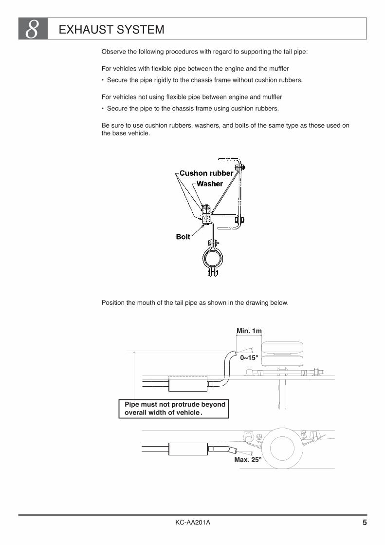
EXHAUST SYSTEM8
KC-AA201A 5
Observe the following procedures with regard to supporting the tail pipe:
For vehicles with flexible pipe between the engine and the muffler• Secure the pipe rigidly to the chassis frame without cushion rubbers.
For vehicles not using flexible pipe between engine and muffler• Secure the pipe to the chassis frame using cushion rubbers.
Be sure to use cushion rubbers, washers, and bolts of the same type as those used on the base vehicle.
Position the mouth of the tail pipe as shown in the drawing below.
Min. 1m
0~15°
Max. 25°
Pipe must not protrude beyondoverall width of vehicle .

EXHAUST SYSTEM8
KC-AA201A 6
Clearances between exhaust parts and other parts The exhaust system becomes very hot during driving. Observe the following procedures to prevent vehicle fires.
Clearances from body parts When mounting a body or equipment, observe the precautions given in this section.
Clearances from fuel system parts• Maintain a clearance of at least 200mm between the fuel tank, fuel pipes, etc. and the
hot parts of the exhaust system. If you cannot maintain a clearance of 200mm, fit heat insulators to protect the fuel tank and fuel pipes. When arranging fuel piping, make sure that even if a fuel line ruptures and fuel leaks out, no fuel will come into contact with the hot parts of the exhaust system.
• Never make joints in the fuel pipes above the hot parts of the exhaust system, etc.• When moving the fuel tank or installing an additional tank, make sure that the filling
port is at least 300mm away from the mouth of the tail pipe and at least 200mm away from exposed electrical terminals.
Clearances from other chassis parts Maintain the clearances shown in the table below. If you cannot maintain these clearances, fit heat insulators.

KC-AA201A
Chapter 9BATTERY
1. WIRING PRECAUTIONS •••••••••••••••••••••••••••••••••••••• 2 2. CHANGE OF BATTERY MOUNTING POSITION •••••••• 3 3. NO OVERLAID CONNECTION OF
BATTERY CABLE •••••••••••••••••••••••••••••••••••••••••••• 3 4. REPLACEMENT BATTERY CABLE •••••••••••••••••••••••• 3 5. SERVICEABILITY ••••••••••••••••••••••••••••••••••••••••••••••• 4
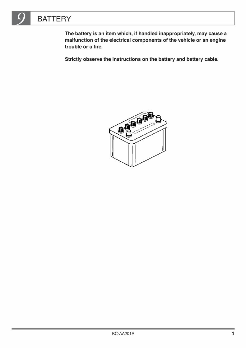
BATTERY9
KC-AA201A 1
The battery is an item which, if handled inappropriately, may cause a malfunction of the electrical components of the vehicle or an engine trouble or a fire.
Strictly observe the instructions on the battery and battery cable.

BATTERY9
KC-AA201A 2
1. WIRING PRECAUTIONS
In order to prevent damage from water or their objects, protect the battery appropriately.
The battery cable, whether in or out of position, should not be in contact with a sharp edge of other portions.
Clip the battery cable at intervals of less than 450mm. (Always use a clip lined with rubber.)• Be sure that the clip is not freely movable.• Keep the clips away from other portions.
Don’t bend the battery cable to a radius smaller than ten times of the cable diameter.
If the terminal is moved under the body or equipment mounting of the battery cable, the terminal would become loose and engine start would become impossible, often leading to a battery failure. Always securely fix the battery cable on the battery tray.
Set the route of the battery cable downward so that no leverage action is exerted to loosen the connect.
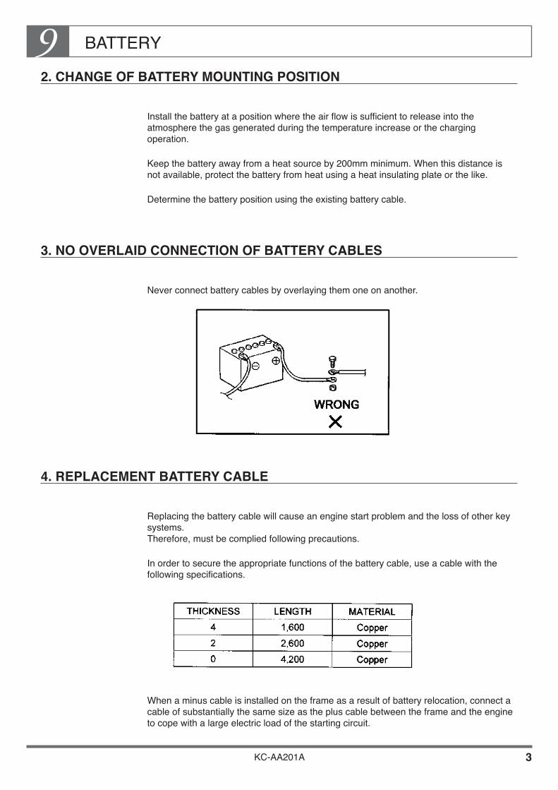
BATTERY9
KC-AA201A 3
2. CHANGE OF BATTERY MOUNTING POSITION
Install the battery at a position where the air flow is sufficient to release into the atmosphere the gas generated during the temperature increase or the charging operation.
Keep the battery away from a heat source by 200mm minimum. When this distance is not available, protect the battery from heat using a heat insulating plate or the like.
Determine the battery position using the existing battery cable.
3. NO OVERLAID CONNECTION OF BATTERY CABLES
Never connect battery cables by overlaying them one on another.
4. REPLACEMENT BATTERY CABLE
Replacing the battery cable will cause an engine start problem and the loss of other key systems. Therefore, must be complied following precautions.
In order to secure the appropriate functions of the battery cable, use a cable with the following specifications.
When a minus cable is installed on the frame as a result of battery relocation, connect a cable of substantially the same size as the plus cable between the frame and the engine to cope with a large electric load of the starting circuit.

BATTERY9
KC-AA201A 4
5. SERVICEABILITY
During the service or check work, secure a sufficient space or insulation in order not to cause any accident such as short circuit.
Attach a terminal polarity marking, a caution label and an gravity meter (mark) at an easily visible position.

KC-AA201A
Chapter 10SUSPENSION AND TIRE
1. SUSPENSIONS USED IN THE CHASSIS ••••••••••••••••• 1 2. PROHIBITED MODIFICATION OR ALTERATION ••••••• 2 3. SERVICEABILITY ••••••••••••••••••••••••••••••••••••••••••••••• 3 4. OTHER PRECAUTIONS WHEN MOUNTING
OR MODIFICATION •••••••••••••••••••••••••••••••••••••••••• 4 5. TIRE •••••••••••••••••••••••••••••••••••••••••••••••••••••••••••••••• 6
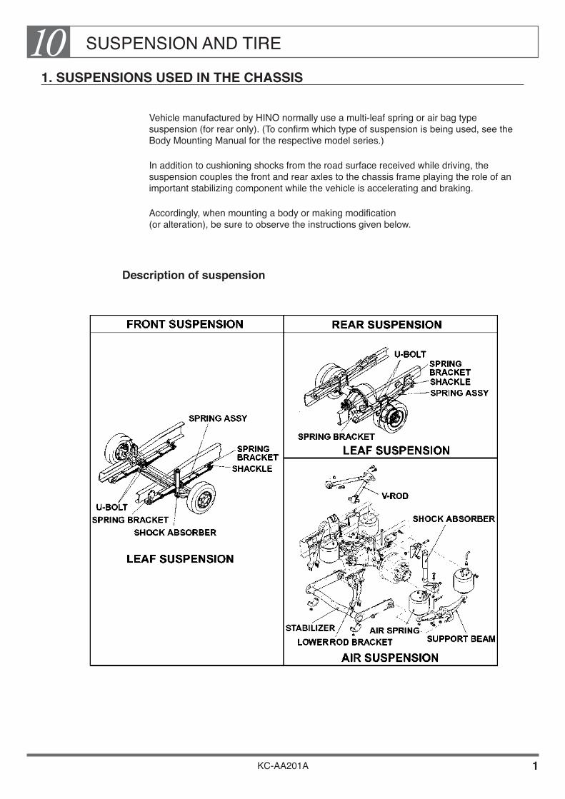
SUSPENSION AND TIRE10
KC-AA201A 1
1. SUSPENSIONS USED IN THE CHASSIS
Vehicle manufactured by HINO normally use a multi-leaf spring or air bag type suspension (for rear only). (To confirm which type of suspension is being used, see the Body Mounting Manual for the respective model series.)
In addition to cushioning shocks from the road surface received while driving, the suspension couples the front and rear axles to the chassis frame playing the role of an important stabilizing component while the vehicle is accelerating and braking.
Accordingly, when mounting a body or making modification (or alteration), be sure to observe the instructions given below.
Description of suspension
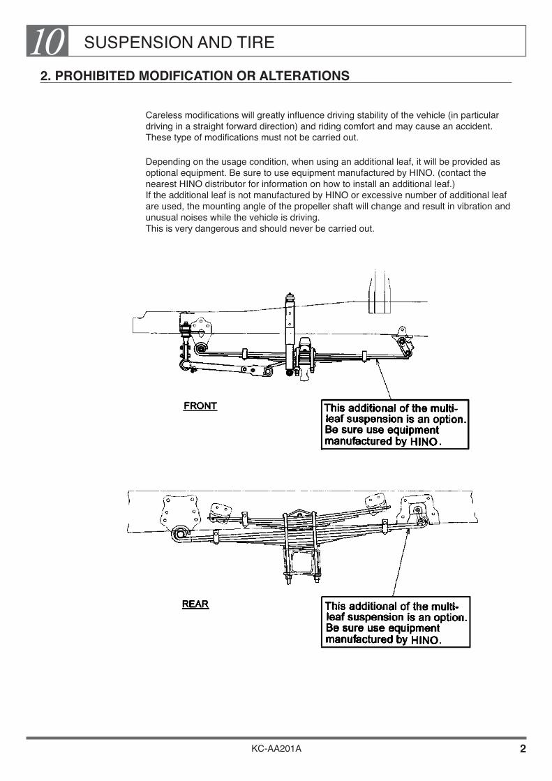
SUSPENSION AND TIRE10
KC-AA201A 2
2. PROHIBITED MODIFICATION OR ALTERATIONS
Careless modifications will greatly influence driving stability of the vehicle (in particular driving in a straight forward direction) and riding comfort and may cause an accident. These type of modifications must not be carried out.
Depending on the usage condition, when using an additional leaf, it will be provided as optional equipment. Be sure to use equipment manufactured by HINO. (contact the nearest HINO distributor for information on how to install an additional leaf.) If the additional leaf is not manufactured by HINO or excessive number of additional leaf are used, the mounting angle of the propeller shaft will change and result in vibration and unusual noises while the vehicle is driving. This is very dangerous and should never be carried out.
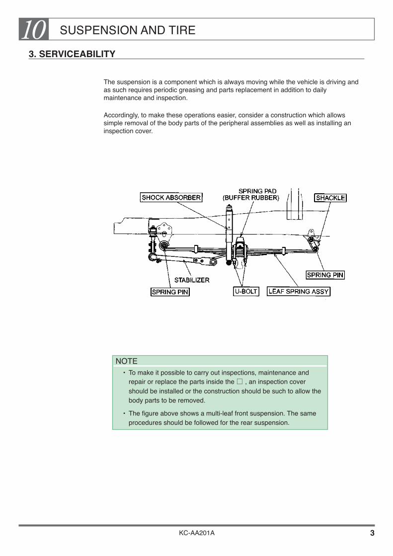
SUSPENSION AND TIRE10
KC-AA201A 3
3. SERVICEABILITY
The suspension is a component which is always moving while the vehicle is driving and as such requires periodic greasing and parts replacement in addition to daily maintenance and inspection.
Accordingly, to make these operations easier, consider a construction which allows simple removal of the body parts of the peripheral assemblies as well as installing an inspection cover.
NOTE• To make it possible to carry out inspections, maintenance and
repair or replace the parts inside the , an inspection cover should be installed or the construction should be such to allow the body parts to be removed.
• The figure above shows a multi-leaf front suspension. The same procedures should be followed for the rear suspension.
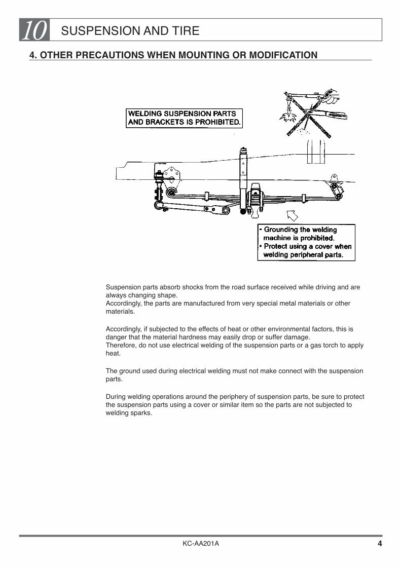
SUSPENSION AND TIRE10
KC-AA201A 4
4. OTHER PRECAUTIONS WHEN MOUNTING OR MODIFICATION
Suspension parts absorb shocks from the road surface received while driving and are always changing shape. Accordingly, the parts are manufactured from very special metal materials or other materials.
Accordingly, if subjected to the effects of heat or other environmental factors, this is danger that the material hardness may easily drop or suffer damage. Therefore, do not use electrical welding of the suspension parts or a gas torch to apply heat.
The ground used during electrical welding must not make connect with the suspension parts.
During welding operations around the periphery of suspension parts, be sure to protect the suspension parts using a cover or similar item so the parts are not subjected to welding sparks.

SUSPENSION AND TIRE10
KC-AA201A 5
Because in the peripheral portion of the bracket where the suspension parts are installed constantly a large amount of stress is generated while the vehicle is driving, heat must not be applied to this portion by electrical welding or a gas torch.
NOTE• The figure above only shows a multi-leaf suspension. The same precautions
also apply to air bag type rear suspension as well.
• Make alterations taking into consideration the upper bound limit of the differential carrier and the tire so that the tire does not interfere with the body, etc. when the vehicle bounds on rough roads. For vehicles destined for districts where installation of the tire chain is required, add the tire chain clearance to the upper limit consideration. (For more details, refer to the Body Mounting Manual for the respective model series.)
• In the case where the vehicle is equipped with a rear axle breather and a hose, take care not to bend, distort or enclose them or otherwise interfere with normal “breathing” of the rear axle.
• The leaf spring should be installed at a point distant from the exhaust pipe by 50mm minimum and from the muffler by 150mm minimum. In the case where these distances cannot be secured, protect the vehicle against heat using a heat insulating plate or the like.

SUSPENSION AND TIRE10
KC-AA201A 6
5. TIRE
A chassis on which genuine tires are mounted sent to the body mount manufacturer.
Don’t use any tire or disc other than specified for the particular vehicle.
While mounting the body, there is a danger that scratches, paint adhesion, or other damage may occur during welding and other operations. Be sure to observe the instructions for the mounting operation given below.
Precautions Before Start Body Mounting or Alteration Work
While mounting the body, attach covers to tires to prevent paint deposit and damages to tires. Or begin body mounting after changing tires to dummy tires.
Body Mounting or Modification
MOUNTING A REAR FENDER & MUDGUARD
Install a rear fender & mudguard to protect the chassis parts from dust, water, or mud thrown up by the tires while the vehicle is driving. (For details on installing the rear fender & splash guard, see the Body Mounting Manual for the respective model series.)
KC-AA201A
Chapter 11SPARE TIRE CARRIER
1. RECOMMENDED SPARE TIRE CARRIER •••••••••••••••• 2 2. GENERAL PREVENTIVE MEASURES ••••••••••••••••••••• 2 3. PREVENTIVE MEASURE FOR ADDITION OR ALTERATION
TO SPARE TIRE CARRIER OF WIND-UP TYPE •••••••••••• 3 4. OTHER •••••••••••••••••••••••••••••••••••••••••••••••••••••••••••• 4
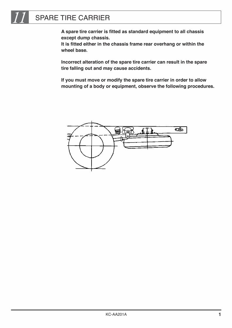
SPARE TIRE CARRIER11
KC-AA201A 1
A spare tire carrier is fitted as standard equipment to all chassis except dump chassis. It is fitted either in the chassis frame rear overhang or within the wheel base.
Incorrect alteration of the spare tire carrier can result in the spare tire falling out and may cause accidents.
If you must move or modify the spare tire carrier in order to allow mounting of a body or equipment, observe the following procedures.

SPARE TIRE CARRIER11
KC-AA201A 2
1. RECOMMENDED SPARE TIRE CARRIER
The spare tire carrier must have sufficient strength and wear resistance to prevent the spare tire from falling out during driving. Use only genuine HINO parts.
2. GENERAL PREVENTIVE MEASURES
When mounting a spare tire carrier, make sure that it has sufficient strength and wear resistance to carry the tire, and also that• construct the vehicle in such a way as to facilitate the mounting and demounting of the
spare tire by a single person.• construct the vehicle with the spare tire not in contact with the parts other than the
stopper when mounted.• be sure that the chain or the like is not caught up when the tire is wound up.• don’tinstallthebuiltoralteredequipmentwithintheoperatingrangeofthesparetire
carrier handle.
• construct the spare tire carrier in such a way that even a punctured tire can be fixed securely.
• the construction should be such that the tire is stored within the outermost side of the vehicle and be sure to keep the enough height from ground to avoid contact with ground during driving.
• construct the spare tire carrier in such a manner that the tire is fixed at a position 100mm minimum away from the exhaust pipe and 200mm minimum away from the muffler. In the case where no sufficient clearance is available, take an appropriate measure to protect the spare tire carrier against heat by a heat insulating plate or the like.
• construct the spare tire carrier to be kept the enough clearance with movable or rotating parts of mounted body and chassis when mounting or demounting of the spare tire.
• be strictly prohibited a slope construction of the spare tire carrier excluding the slope due to vehicle inclination or chassis frame structure.
• attach the caution plate for the spare tire at a position easily visible from the operating point.
NOTE Confirm the chassis drawing where spare tire carrier is installed in Body
Mounting Manual for the respective model series.

SPARE TIRE CARRIER11
KC-AA201A 3
3. PREVENTIVE MEASURE FOR ADDITION OR ALTERATION TO SPARE TIRE CARRIER OF WIND-UP TYPE
Disc Wheel Support
The support should be so constructed as not to be deformed with a sufficient contact area with the disc wheel.
Evenifthetiretobecarriedispunctured,thestructuregivesadequatetighteningresistance.
Tire Rubber Support
If the tire is supported by the tire rubber itself, the distance between the supports is close to the maximum width of the tire and the supports are covered by cushion rubbers which are firmly fixed to the supports.
Ifthetiretobecarriedispunctured,thestructuregivesadequatetighteningresistance.
NOTE• In the case of spare tire carrier with tire rubber support type, it is difficult to get adequatetighteningresistancewhenthetiretobecarriedispunctured. It is therefore advised to install the disc stopper to the carrier itself or construct a such that tire disc is contacted with installation bracket as following figure.
TIRE STOPPER DISC STOPPER
PUNCTURED TIRE DISC
The carrier must have a stopper that will give adequate tightening resistance even with a punctured tire.

SPARE TIRE CARRIER11
KC-AA201A 4
4. OTHER
Item 2 listed precautions for maintaining performance standards. In this section are mentioned other basic precautions.
Mounting Position
Make sure that the spare tire carrier is mounted sufficiently high to prevent grounding during driving on rough roads and in reverse. Make sure that the carrier does not protrude beyond the end of the rear overhang or beyond the overall width of the vehicle.
Maintain proper clearances from rotating, moving, or hot parts (drive shaft, spring, brake hoses, exhaust system, etc.).
Make sure the mounting position allows enough space to remove and install the spare tire.
Mounting the Carrier Bracket
The spare tire carrier may be mounted on the side rail using bolts, rivets, or welding. Whatever the method you use, make sure that it does not adversely affect the strength of either the bracket or the side rail, and observe the precautions listed in Section 2, “CHASSIS FRAME”. When mounting the carrier bracket using bolts, make sure the bolts are properly tightened but that they can be tightened further if the need arises.
Caution Plate for Carrier Tightening Torque
Fitacautionplateshowingthepropertighteningtorqueforthecarrierinavisiblelocationas close as possible to the carrier.
The style of the caution plate should be similar to that of a genuine HINO caution plate.

SPARE TIRE CARRIER11
KC-AA201A 5
[ Example ]
How to Handle the Spare Tire• Mark sure that claw of hanging plate and disk wheel are properly located.• Do not wind up spare tire when chain is twisted.• Remove mud from contact surfaces and wind handle until it stops, then
tighten with 30 ~ 40 kg force (max. strength of adult using one hand).• After tightening, make sure that the claw of hanging plate is not caught on
the contact surface, and remove handle without winding back.
Spare Tire Carrier
When the tire is secured in place, make sure that dimension “h”iswithinthemarker’srecommendedrange.(Importantwithregardtochainstrength)
When fitting a carrier with lock mechanism, make sure that dimension “h” is within ± 1.5 mmofthemaker’srecommendedvalue. The lock mechanism will not work if this tolerance is not observed.
Mounting the Carrier at an Angle
As a rule, the carrier should not be mounted at an angle, except when the slope is due to the structure of the chassis frame.
Name
Plate, Caution plate
HINO No.
76577-1041
HANGING PLATE CLAW
h
TIRE CARRIER ASSEMBLY
CARRIER BASE POSITION
UPPER SURFACE OF DISC
HANGING PLATE
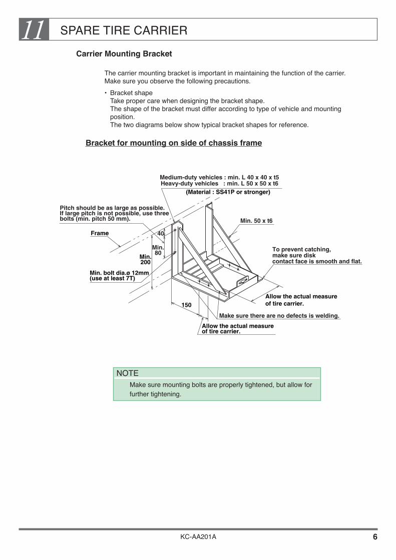
SPARE TIRE CARRIER11
KC-AA201A 6
Carrier Mounting Bracket
The carrier mounting bracket is important in maintaining the function of the carrier. Make sure you observe the following precautions.• Bracket shape
Take proper care when designing the bracket shape. The shape of the bracket must differ according to type of vehicle and mounting position. The two diagrams below show typical bracket shapes for reference.
Bracket for mounting on side of chassis frame
Make sure there are no defects is welding.
To prevent catching, make sure disk contact face is smooth and flat.
Min. 50 x t6
Pitch should be as large as possible.If large pitch is not possible, use three bolts (min. pitch 50 mm).
Frame 40
Min.80
Min.200
Min. bolt dia.ø 12mm(use at least 7T)
150
Allow the actual measure of tire carrier.
Allow the actual measureof tire carrier.
Medium-duty vehicles : min. L 40 x 40 x t5
(Material : SS41P or stronger)Heavy-duty vehicles : min. L 50 x 50 x t6
NOTE Make sure mounting bolts are properly tightened, but allow for
further tightening.
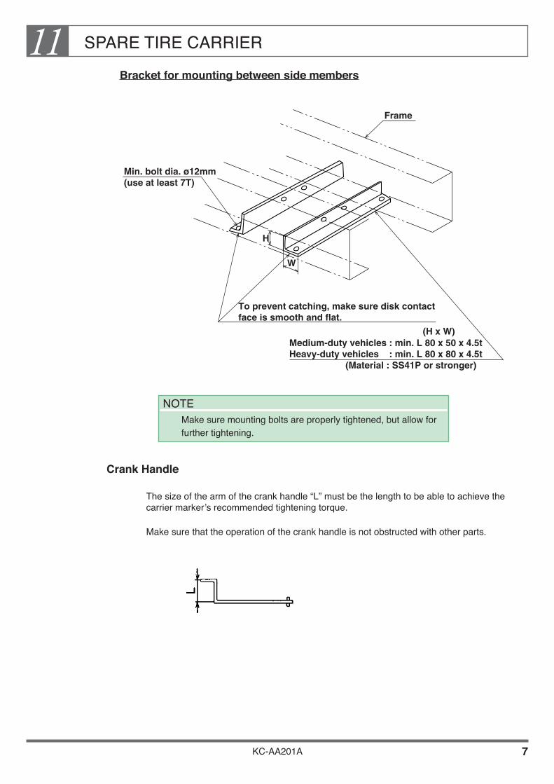
SPARE TIRE CARRIER11
KC-AA201A 7
Bracket for mounting between side members
Crank Handle
The size of the arm of the crank handle “L” must be the length to be able to achieve the carriermarker’srecommendedtighteningtorque.
Make sure that the operation of the crank handle is not obstructed with other parts.
Min. bolt dia. ø12mm(use at least 7T)
Frame
(Material : SS41P or stronger)
To prevent catching, make sure disk contact face is smooth and flat.
Medium-duty vehicles : min. L 80 x 50 x 4.5t Heavy-duty vehicles : min. L 80 x 80 x 4.5t
(H x W)
H
W
NOTE Make sure mounting bolts are properly tightened, but allow for
further tightening.
KC-AA201A
Chapter 12BODY & EQUIPMENT MOUNTING
1. DESIGN OF BODY OR EQUIPMENT MOUNTING •••••• 2 2. SPACER ••••••••••••••••••••••••••••••••••••••••••••••••••••••••••• 12 3. MOUNTING METHOD OF BODY OR EQUIPMENT ••••• 13 4. INSPECTION LID ••••••••••••••••••••••••••••••••••••••••••••••• 23 5. REAR FENDER •••••••••••••••••••••••••••••••••••••••••••••••••• 24 6. CHASSIS FRAME ••••••••••••••••••••••••••••••••••••••••••••••• 26 7. BODY OFFSET •••••••••••••••••••••••••••••••••••••••••••••••••• 27 8. DATUM HOLE ON REAR AXLE CENTER
FOR BODY MOUNTING •••••••••••••••••••••••••••••••••••• 27 9. REAR BODY ••••••••••••••••••••••••••••••••••••••••••••••••••••• 28 10. MOUNTING OF SPECIAL REAR BODY ••••••••••••••••••• 30

BODY & EQUIPMENT MOUNTING12
KC-AA201A 1
Improper mounting of a body or equipment may cause cracks in the chassis frame or cause serious problems such as poor steerability.
You should take particular care when designing and fitting a main sill (subframe).
If you intend to mount a body or equipment, be sure to observe the instructions given in this section.

BODY & EQUIPMENT MOUNTING12
KC-AA201A 2
1. DESIGN OF BODY OR EQUIPMENT MOUNTING
Main Sill (Subframe)
When mounting a body or equipment, always fit a main sill (subframe) on the top surface of the side member of the chassis frame.
When mounting the main sill on top of the side member, be sure that you position it so as to disperse the stress placed on the frame by loading. Also be sure to secure all mechanisms of the body unit to the main sill, except for the combination parts between the main sill and the chassis frame. Fit a spacer between the main sill and the side frame to lift the main sill off the rivet heads of the side frame.
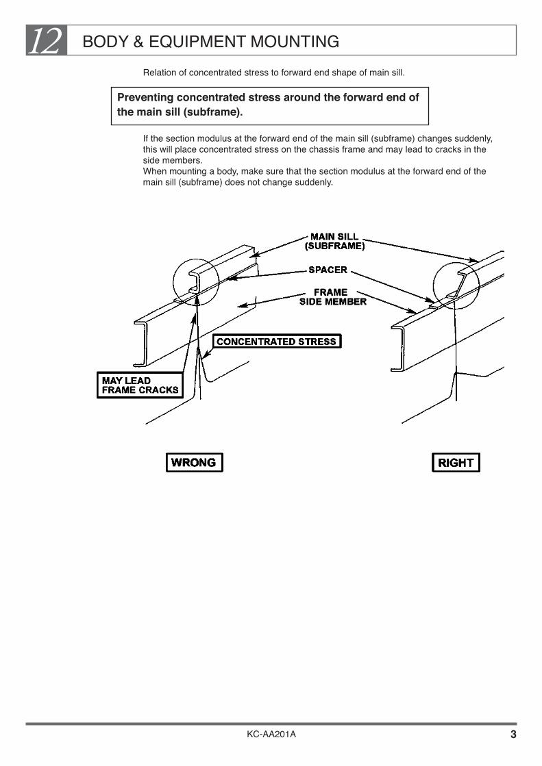
BODY & EQUIPMENT MOUNTING12
KC-AA201A 3
Relation of concentrated stress to forward end shape of main sill.
Preventing concentrated stress around the forward end of the main sill (subframe).
If the section modulus at the forward end of the main sill (subframe) changes suddenly, this will place concentrated stress on the chassis frame and may lead to cracks in the side members. When mounting a body, make sure that the section modulus at the forward end of the main sill (subframe) does not change suddenly.

BODY & EQUIPMENT MOUNTING12
KC-AA201A 4
Forward End of Main Sill (Subframe)
The front end of the main sill, where it contacts the side member, must be shaped as shown in the drawings below.
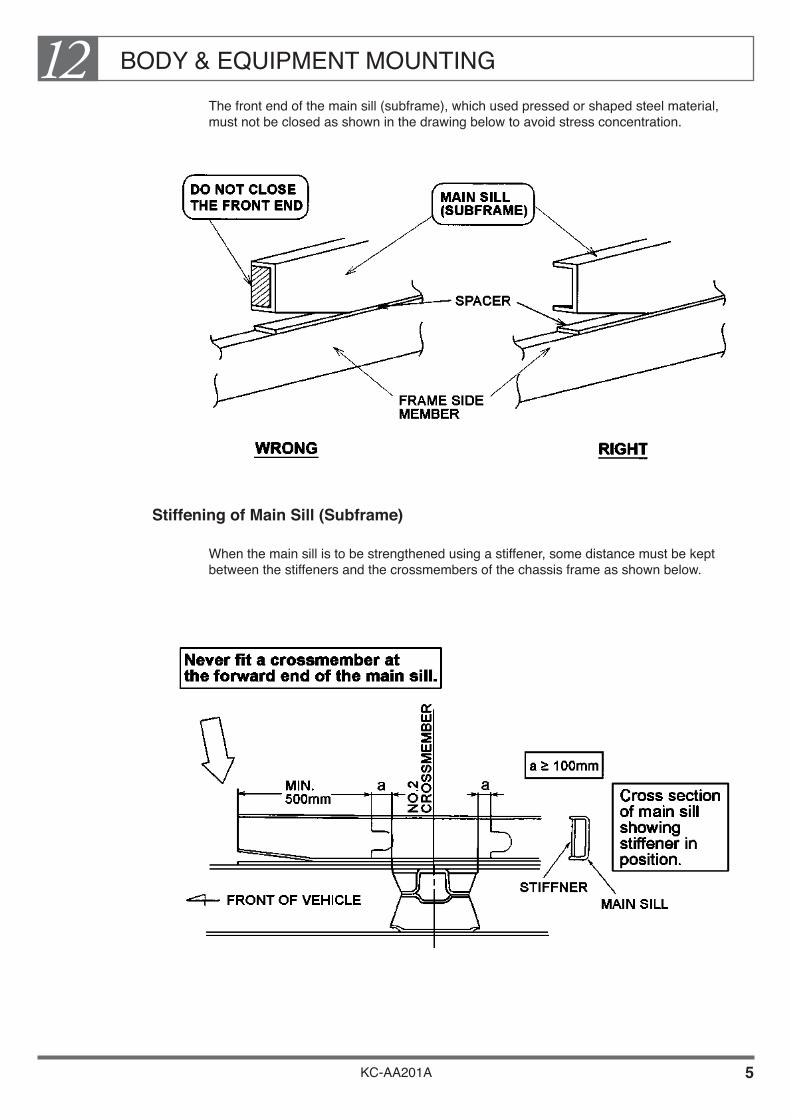
BODY & EQUIPMENT MOUNTING12
KC-AA201A 5
The front end of the main sill (subframe), which used pressed or shaped steel material, must not be closed as shown in the drawing below to avoid stress concentration.
Stiffening of Main Sill (Subframe)
When the main sill is to be strengthened using a stiffener, some distance must be kept between the stiffeners and the crossmembers of the chassis frame as shown below.
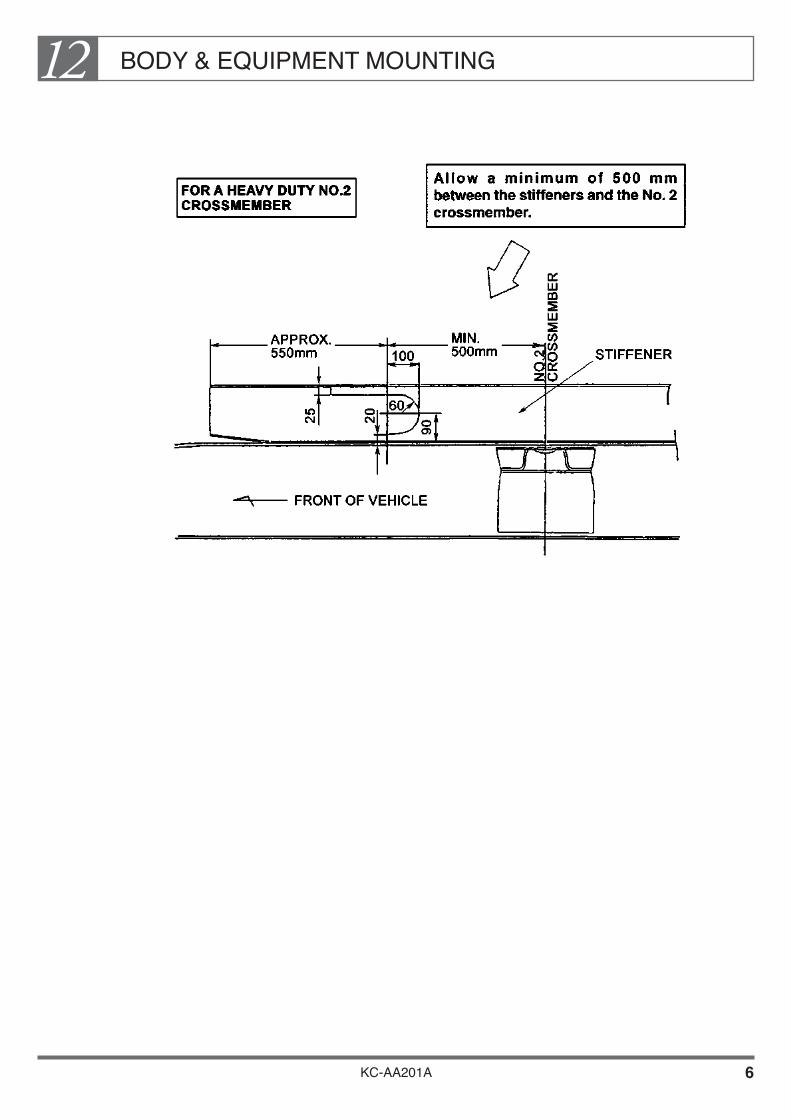
BODY & EQUIPMENT MOUNTING12
KC-AA201A 6

BODY & EQUIPMENT MOUNTING12
KC-AA201A 7
Main Sill Shape for Side Member with Side Offset
If the side member of the chassis frame has a side offset, the main sill must follow the contour of the side member. The kick-up point of the main sill must be at least 50 mm from the deflection point of the side member in order to disperse stress.

BODY & EQUIPMENT MOUNTING12
KC-AA201A 8
Extension of Main Sill (Subframe)
The main sill should extend as far as possible towards the back of the cab to minimize car-shake (vibration) and prevent the creation of weak areas in the side frame.
Positioning Forward End of Main Sill for Rigidity of Body or Equipment
For trucks with highly rigid bodies such as tank lorries, LPG lorries, and van body trucks (especially refrigerator trucks), etc., be sure to select the chassis model and design the body so that the main sill extends as far as possible toward the back of the cab.
If for unavoidable reasons, such as axle mass distribution, you must leave a large gap between the body or equipment and the back of the cab, extend the main sill as far as possible toward the back of the cab and secure it firmly to the chassis frame.

BODY & EQUIPMENT MOUNTING12
KC-AA201A 9
Example : Mounting a bulk cement body on an FS series truck• The distance between the rear edge of the cab arch and the main sill (A) should be
less than 120 mm.• The foremost U-bolt or mounting bracket should be positioned within 500 mm of the
rear edge of the cab arch (B) and should be firmly secured to the chassis frame side member.
• If at all possible, the exposed length of main sill alone should be less than 1,400 mm (C).
• If at all possible, the body and main sill should be joined by stays (one each, left and right) or other similar means.
Unit : mm
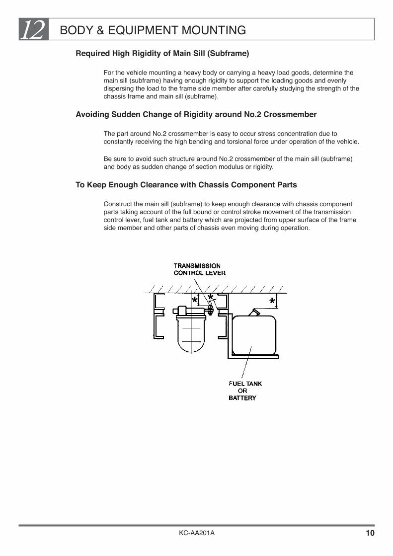
BODY & EQUIPMENT MOUNTING12
KC-AA201A 10
Required High Rigidity of Main Sill (Subframe)
For the vehicle mounting a heavy body or carrying a heavy load goods, determine the main sill (subframe) having enough rigidity to support the loading goods and evenly dispersing the load to the frame side member after carefully studying the strength of the chassis frame and main sill (subframe).
Avoiding Sudden Change of Rigidity around No.2 Crossmember
The part around No.2 crossmember is easy to occur stress concentration due to constantly receiving the high bending and torsional force under operation of the vehicle.
Be sure to avoid such structure around No.2 crossmember of the main sill (subframe) and body as sudden change of section modulus or rigidity.
To Keep Enough Clearance with Chassis Component Parts
Construct the main sill (subframe) to keep enough clearance with chassis component parts taking account of the full bound or control stroke movement of the transmission control lever, fuel tank and battery which are projected from upper surface of the frame side member and other parts of chassis even moving during operation.
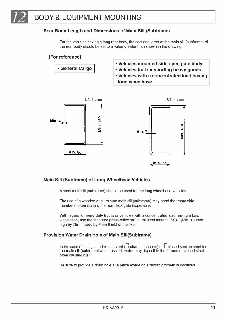
BODY & EQUIPMENT MOUNTING12
KC-AA201A 11
Rear Body Length and Dimensions of Main Sill (Subframe)
For the vehicles having a long rear body, the sectional area of the main sill (subframe) of the rear body should be set to a value greater than shown in the drawing.
[For reference]
• General Cargo
UNIT : mm UNIT : mm
Main Sill (Subframe) of Long Wheelbase Vehicles
A steel main sill (subframe) should be used for the long wheelbase vehicles.
The use of a wooden or aluminum main sill (subframe) may bend the frame side members, often making the rear deck gate inoperable.
With regard to heavy duty trucks or vehicles with a concentrated load having a long wheelbase, use the standard press-rolled structural steel material SS41 (Min. 180mm high by 75mm wide by 7mm thick) or the like.
Provision Water Drain Hole of Main Sill(Subframe)
In the case of using a lip-formed steel ( channel-shaped) or closed section steel for the main sill (subframe) and cross sill, water may deposit in the formed or closed steel often causing rust.
Be sure to provide a drain hole at a place where no strength problem is occurred.
• Vehicles mounted side open gate body. • Vehicles for transporting heavy goods. • Vehicles with a concentrated load having long wheelbase.
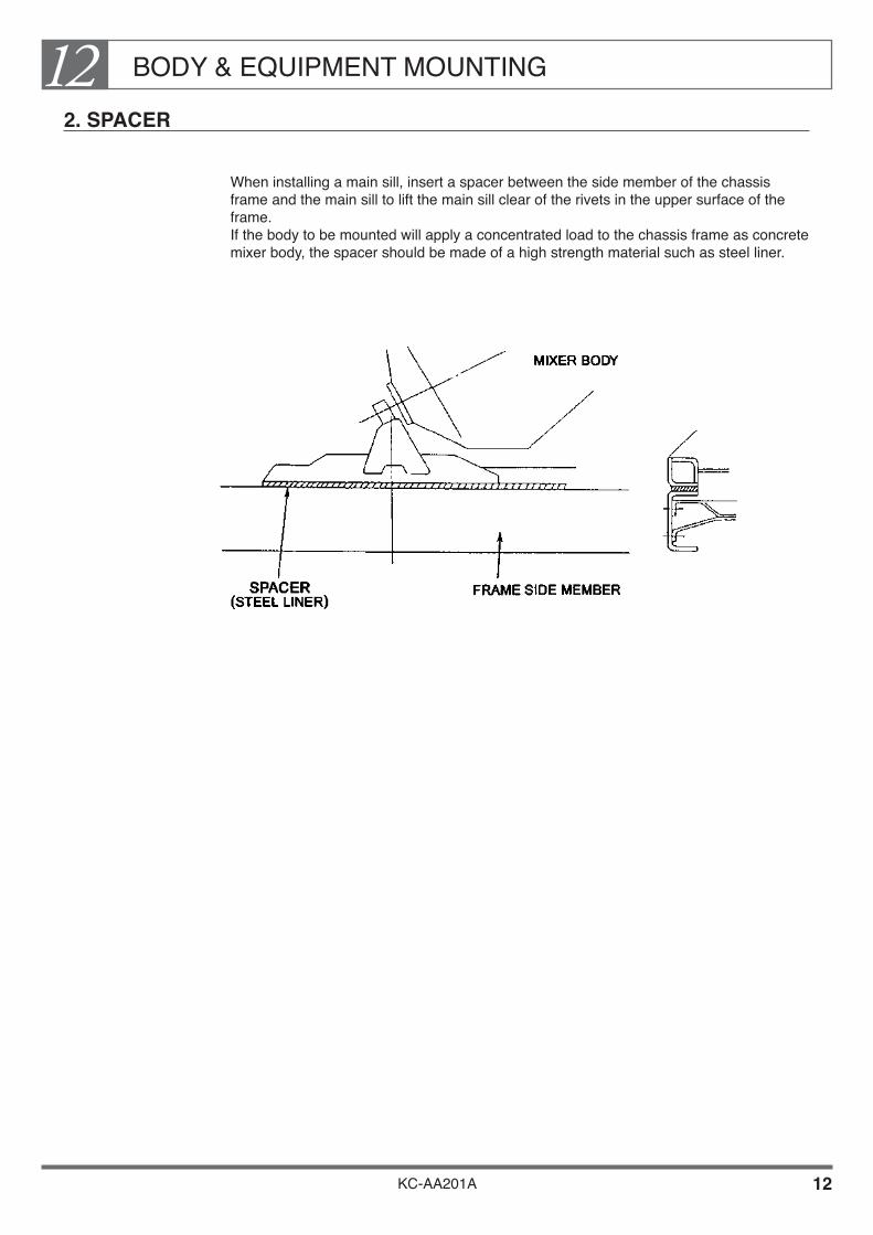
BODY & EQUIPMENT MOUNTING12
KC-AA201A 12
2. SPACER
When installing a main sill, insert a spacer between the side member of the chassis frame and the main sill to lift the main sill clear of the rivets in the upper surface of the frame. If the body to be mounted will apply a concentrated load to the chassis frame as concrete mixer body, the spacer should be made of a high strength material such as steel liner.

BODY & EQUIPMENT MOUNTING12
KC-AA201A 13
3. MOUNTING METHOD OF BODY OR EQUIPMENT
How to Install the Main Sill (Subframe)
Install the main sill (subframe) of the body or equipment on the chassis using U-bolts or brackets. The details of mounting methods are shown in the drawings below.
If the main sill (subframe) even if made of steel to be secured to the chassis, should not be fixed on the frame by welding or bolting on the frame upper flange.

BODY & EQUIPMENT MOUNTING12
KC-AA201A 14
If it is difficult to allow a clearance to the chassis parts, use U-bolts made from steel sheet.
For the locations of the U-bolts used when mounting ordinary body or equipment, see the U-bolt Mounting Position Drawing in the Body Mounting Manual for the respective model series.
For the chassis frame with a -shaped cross section, install a appropriate props at the U-bolt tightening section to prevent deformation of the flange on the frame side member. Refer to Installation Method of U-bolts for more details of the props.
Install main sill (subframe) tightening U-bolts and a appropriate props in such a manner that they do not touch wires, brake pipes, and hoses and that these parts can be inspected, serviced, removed, and reinstalled later. Allow sufficient clearances around rubber hoses because they will move while the vehicle in running. The gap to the rubber hose must be 50 mm or more and the gaps to the brake pipe and valve must be 15 mm or more.
When a prop is required around the exhaust pipe and muffler, use a steel prop.

BODY & EQUIPMENT MOUNTING12
KC-AA201A 15
It is desirable to install the U-bolts at the U-bolt mounting positions (standard positions) shown on the below. Installing U-bolts at other positions will impair the frame strength. As a rule, do not install U-bolts at the positions listed below. If it is unavoidable to install U-bolts at prohibited positions, carefully verify the frame strength.• Point where there is a difference in level on the chassis frame (frame kick point) and
the side offset point (side kick point) The U-bolt mounting position must be 50 mm or more away from the frame kick
point.• Existing hole in the flange of the frame side rail
The U-bolt mounting position must be 40 mm or more away from the existing hole.
• Break point of the frame's inner or outer reinforcement (the section modulus change greatly)
The U-bolt mounting position must be 100 mm or more away from the break point of the inner or outer reinforcement.
• Near the crossmember As a rule, the U-bolt mounting position must be 200 mm or more away from the
crossmember. If impossible, the U-bolt must be at least 100 mm away from the crossmember.
• Stress release point at front end of main sill (subframe).• The details where U-bolt should be installed, see the Body Mounting Manual for the
respective Model Series.
[PROHIBITED RANGE WHERE U-BOLT SHOULD NOT BE INSTALLED]
UNIT : mm
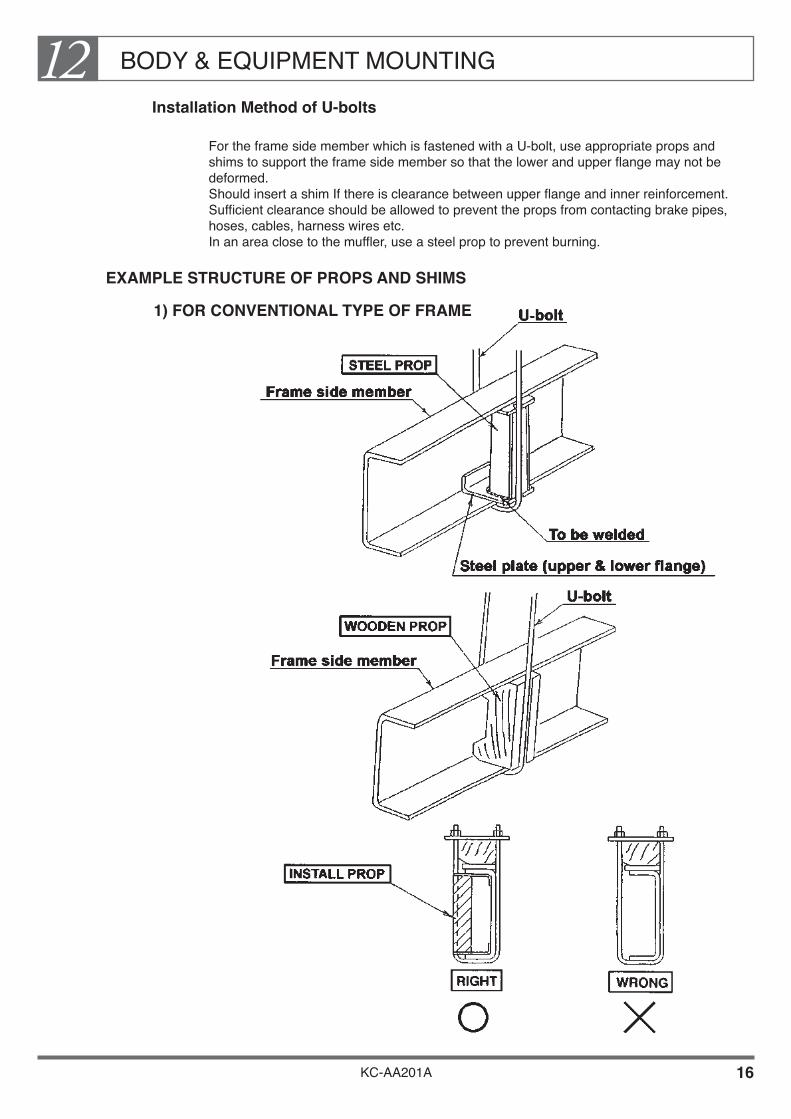
BODY & EQUIPMENT MOUNTING12
KC-AA201A 16
Installation Method of U-bolts
For the frame side member which is fastened with a U-bolt, use appropriate props and shims to support the frame side member so that the lower and upper flange may not be deformed. Should insert a shim If there is clearance between upper flange and inner reinforcement. Sufficient clearance should be allowed to prevent the props from contacting brake pipes, hoses, cables, harness wires etc. In an area close to the muffler, use a steel prop to prevent burning.
EXAMPLE STRUCTURE OF PROPS AND SHIMS
1) FOR CONVENTIONAL TYPE OF FRAME

BODY & EQUIPMENT MOUNTING12
KC-AA201A 17
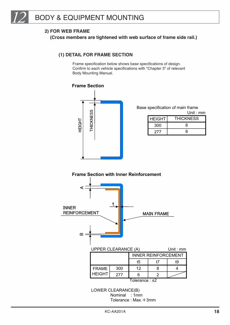
BODY & EQUIPMENT MOUNTING12
KC-AA201A 18
2) FOR WEB FRAME (Cross members are tightened with web surface of frame side rail.)
(1) DETAIL FOR FRAME SECTION
Frame specification below shows base specifications of design. Confirm to each vehicle specifications with "Chapter 3" of relevant Body Mounting Manual.
Frame Section
Base specification of main frameUnit : mm
HEIGHT300277
Frame Section with Inner Reinforcement
UPPER CLEARANCE (A) Unit : mm
t5 t7 t9300 12 8 4277 6 2
Tolerance : ±2
LOWER CLEARANCE(B)Nominal : 1mmTolerance : Max.+3mm
FRAMEHEIGHT
INNER REINFORCEMENT
THICKNESS88H
EIG
HT
TH
ICKN
ESS
AB
t
MAIN FRAME
INNERREINFORCEMENT

BODY & EQUIPMENT MOUNTING12
KC-AA201A 19
(2) RECOMMENDED INSTALLATION METHOD OF U-BOLTFrame Section
Frame Section with Inner Reinforcement
Type A
U-BOLT
PROP
DOUBLE NUTTIGHTENING
DOUBLE NUTTIGHTENING
U-BOLT
PROP
LOWERCLEARANCE
NOTE • Install PROP for avoiding deforming frame flange.
(PROP structure which has shim function for a upper clearance.) • Tightening method is double nut method to prevent from loosening of tightening nut. • If a lower clearance is more then 1 mm, must insert proper steel shim to a lower clearance, if difficult to
ensure tightening torque of U-bolt. (Must perform to prevent dropping shim off, but welding or making hole to the frame flange is prohibited.)
• Must apply proper rust preventive treatment to frame after inserted a shim.
NOTE • Install PROP for avoiding
deforming frame flange. • Tightening method is double
nut method to prevent from loosening of tightening nut.

BODY & EQUIPMENT MOUNTING12
KC-AA201A 20
NOTE • Install PROP for avoiding deforming frame flange. • Insert a steel shim to a upper clearance.
(Must perform to prevent dropping shim off, but welding or making hole to the frame flange is prohibited.) Or Installation method of U-bolt with PROP structure which has shim function.
• Tightening method is double nut method to prevent from loosening of tightening nut. • If a lower clearance is more then 1 mm, must insert proper steel shim to a lower clearance, if difficult to
ensure tightening torque of U-bolt. (Must perform to prevent dropping shim off, but welding or making hole to the frame flange is prohibited.)
• Must apply proper rust preventive treatment to frame after inserted a shim.
Type B
PROP
DOUBLE NUTTIGHTENING
UPPERCLEARANCE
SHIM
U-BOLT

BODY & EQUIPMENT MOUNTING12
KC-AA201A 21
Use of Mounting Brackets
Follow the cautions below in the case where it is unavoidable to use mounting brackets because of the inability of installing a U-bolt due to the body structure.
Installing mounting brackets near crossmembers may place high stress on the side member. Mounting brackets must therefore be positioned at least 200 mm away from the any crossmembers.
If the mounting brackets must be mounted within 200 mm of the end of crossmember, they should be positioned at the center of crossmember.

BODY & EQUIPMENT MOUNTING12
KC-AA201A 22
In bonnet vehicles, the No.2 crossmember coincides with the front end of the main sill. In this case, do not position brackets within 300 mm of the front end of the subframe or main.
Secure mounting brackets to the chassis frame side member with bolts. Be sure not to damage brake pipes or harness wires when drilling holes in the chassis frame. For a general description of how to drill holes in the chassis frame, see clause CHASSIS FRAME.
Example : If you cannot use U-bolts because the body to be mounted is a tank, use mounting brackets in opposing positions. Secure the brackets as shown in the drawing below.

BODY & EQUIPMENT MOUNTING12
KC-AA201A 23
4. INSPECTION LIDS
To facilitate inspection and maintenance of the transmission and rear axle, wherever possible, install inspection lids in the floor of the body or equipment.
Transmission Inspection Lid
In forward control vehicles, the transmission is located behind the cab. An inspection lid should be positioned as shown in the drawing below to facilitate inspection and maintenance.
Rear Axle Inspection Lid
When the rear rearward axle of a heavy vehicle is to be removed, work is made far easier if the axle can be lifted using a block and tackle. Except where considerations of body strength prohibit this, you should if possible, install an inspection lid measuring 400 x 400 mm in the center of the floor of the body, just forward of the rear rearward axle to allow this procedure. If a cross sill crosses the hole, the length of the hole should be extended to give a total unobstructed length of 400 mm.
UNIT : mm
APROX.1100mm
HEAD CONSTRUCTION BODY
600mm
400
FRONT OF VEHICLE
FRONTREARWARDAXLE
REARREARWARDAXLE
400

BODY & EQUIPMENT MOUNTING12
KC-AA201A 24
5. REAR FENDER
Precautions for Installing Rear Fenders
Install the rear fenders conforming to vehicle safety regulations, and allow sufficient clearance between the tires and the floor of the body so that the tires do not contact the fenders. For details of clearances, see Rear Tire Deflection in the Body Mounting Manual for the respective model series. If there is a possibility that tire chains may have to be fitted, you should allow an extra clearance of 50 mm.
For safety and extra rigidity, the outer edge of the rear fender should turn inward as shown in the drawing below. The inside edge should also be turned inward of rigidity.
In models with two rear axles such as the FS series, if you plan to fit fenders of the shape shown in the drawing below, be sure to make a hole at " A" to allow water to drain away.
The outer edge of the fender should project at least 10 mm beyond the side of the tire provided the overall width of the vehicle does not exceed 2,500 mm. The fenders must cover the tires over a segment of at least 30º in front and 50º behind the center of the hub (see drawing above).
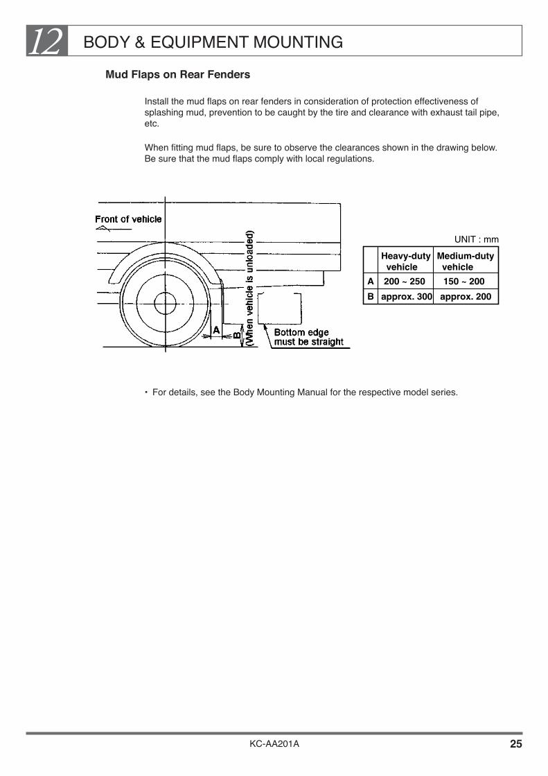
BODY & EQUIPMENT MOUNTING12
KC-AA201A 25
Mud Flaps on Rear Fenders
Install the mud flaps on rear fenders in consideration of protection effectiveness of splashing mud, prevention to be caught by the tire and clearance with exhaust tail pipe, etc.
When fitting mud flaps, be sure to observe the clearances shown in the drawing below. Be sure that the mud flaps comply with local regulations.
• For details, see the Body Mounting Manual for the respective model series.
Heavy-duty vehicle
Medium-duty vehicle
UNIT : mm
200 ~ 250 150 ~ 200
approx. 300
A
B approx. 200

BODY & EQUIPMENT MOUNTING12
KC-AA201A 26
6. CHASSIS FRAME
Rivet Dimensions
The drawing below shows the dimensions of the rivets used in the chassis frame. When mounting a main sill (subframe) you will need to allow holes to accommodate the rivet heads either in the main sill itself or in a spacer.
Tolerances of Chassis Frame Assembly Width and Height
d D H Locations Used
ø10 ø16 7Top and bottom faces of side members(medium and heavy-duty vehicles)
ø11 ø18 8Crossmembers forward and rearward of rear axle(medium-duty vehicles)
ø13 ø21 9Top and bottom faces of side members(medium and heavy-duty vehicles)
ø16 ø26 11Some gussets and crossmembers ;top and bottom faces of side members(heavy-duty vehicles)
UNIT : mm
Vehicle type Overall width Height Width
UNIT : mm
± 2+ 1 0
± 3
Medium-duty vehiclesHeavy-duty vehicles
+ 1 0
+ 3 - 1
+ 3 - 1

BODY & EQUIPMENT MOUNTING12
KC-AA201A 27
7. BODY OFFSET
For mounting the dump or concrete mixer body, determine the body offset as small as possible in order to get enough load on the rear tires getting good driving ability on unpaved road.
8. DATUM HOLE ON REAR AXLE CENTER FOR BODY MOUNTING
When body offset position on the chassis frame is to be determined, make use of rear axle datum line holes (ø9) on the frame side member.

BODY & EQUIPMENT MOUNTING12
KC-AA201A 28
9. REAR BODY
In order to prevent intrusion of dust and exhaust gas into the rear body, securely seal all the holes and apertures in the body floor (deck) except water drain hole as dump body.
Don't remove the insulator from base vehicle.
When mounting a rear body, must be taken the following precautions;
Prevention of Cargo Drop
Each customer (driver) is responsible for preventing his/her cargo from falling. The body-builder therefore is required to take a measure for cargo-fall prevention most suitable for the normal cargo of the particular customer.• Since the general cargo can be bound only laterally, the front portion of the deck is
effectively covered with a wire mesh or iron sheets.
• In the case of dump body, a rear view window on the front wall of the vessel is effectively covered with a wire mesh and a protector (steel cover) must be also installed on front portion on the subframe.

BODY & EQUIPMENT MOUNTING12
KC-AA201A 29
• In the case of vehicles for carrying long or heavy objects, take adequate care in reinforcing the guard frame and the connection between the guard frame and the floor.
• In case that the clearance between cab and rear body (special equipment) increases 60 mm or more due to special equipment mounting, take such a construction to prevent from loading goods falling by the addition of a plate and so on.
Building Side Gate of Separate Type
For the side gate of the rear body which is open deck cargo body, recommend a three-way open gate type (rigid piece side gate) keeping bending rigidity of rear body to avoid deformation of the chassis frame rear overhang.
In change the side gate of rear body from rigid piece to separate type, provide the center pole at forward position of rear axle between wheelbase.
And be sure to reinforce the center pole to keep the bending rigidity same with rigid piece of side gate.

BODY & EQUIPMENT MOUNTING12
KC-AA201A 30
10. MOUNTING OF SPECIAL REAR BODY
Precautions for Mounting the Dump Body
Dump hinge position
To ensure stability of the vehicle when the rear body (dump vessel) is raised, the dump hinge must be installed as close to the rear spring bracket as possible.
Measures directed toward the dump control system
To prevent accidental operation of the dump body during vehicle inspection or maintenance, you should observe the following precautions and fit a protector to the control system.
Make sure that the control link system cannot be reached from the upper side of the frame. Example 1 : Mount a large cover over the link system
Example 2 : Install the link system on the underside of the frame.
Cable
P
Cover
Link system
FRAME
Cable
P
Link system
FRAME

BODY & EQUIPMENT MOUNTING12
KC-AA201A 31
Example 3 : Connect the control cable directly to the hydraulic pump to eliminate the need for intermediate link levers, etc.
Make sure that the link levers are easily accessible for lubrication or if possible use oilless link levers. Examples :• Fit the lubrication port on the side of the frame• Mount the link levers so that they can be lubricated from the underside of the
chassisframe, without raising the load platform.• Use an oilless link system.
Make sure that any operating levers inside the cab lock automatically in both ON and OFF positions.
Precaution for routing the dump control cable The dump control lever was installed as optional equipment when the chassis was assembled. Design and install the control cable while mounting the rear body. Route the cable in such a manner that it does not touch the edges of the frame and brackets and the movable portions such as various control links and engine. After routing the dump control cable, check that it does not touch the above edges and movable portions. Do not forget to check that the dump control lever does not touch the transmission shift lever by operating the shift lever.
Cable
PFRAME

BODY & EQUIPMENT MOUNTING12
KC-AA201A 32
About the safety block
The structure of the safety block (or safety rod) must be designed so that it can be locked and released easily.
Example of structure: The safety block (or safety rod) is installed on the subframe and it is turned up or down (manually).
Inside the cab and also the both sides of the subframe, affix a CAUTION plate explaining the cautions about the handling of the safety block, near the safety block (or safety rod). Inside the cab and also the both sides of the subframe, Affix the CAUTION plate explaining the precautions to be followed when the rear body is raised.
About the instruction manual
In the Instruction Manual, explain the following topics in an easy style:• How to operate the dump system• How to operate the safety block and dump lever lock
KC-AA201A
Chapter 13BODY & EQUIPMENT CONTROLS
1. POWER TAKE OFF (P.T.O.) •••••••••••••••••••••••••••••••••• 2 2. P.T.O. (POWER TAKE OFF) DRIVE SHAFT ••••••••••••••• 4 3. ENGINE CONTROLS FOR BODY OR
EQUIPMENT •••••••••••••••••••••••••••••••••••••••••••••••••• 6 4. ENGINE CONTROLS FOR MECHANICAL
GOVERNOR ••••••••••••••••••••••••••••••••••••••••••••••••••• 11 5. P.T.O. CONTROL (TRANSMISSION SIDE P.T.O.) ••••••• 12

BODY & EQUIPMENT CONTROLS13
KC-AA201A 1
After mounting a body or equipment, you may need to take a power supply from the chassis and fit controls for the body or equipment. When making these modifications, be sure to observe the following precautions.

BODY & EQUIPMENT CONTROLS13
KC-AA201A 2
1. POWER TAKE OFF (P.T.O.)
The Medium and Heavy Duty Truck series may be provided the Power Take Off (P.T.O.) in described following figure as an optional equipment.
General Precautions of P.T.O.
For the P.T.O. fixed to transmission or engine, never permit the unit to exceed the torque and r.p.m. recommended by Hino.• For details of permissible torque and recommended r.p.m., see the Body Mounting
Manual for the respective model series.
When the P.T.O. is operated for a long time in the ordinary condition, a heat protection fixture such as a heat insulator shall be provided in order to prevent fuel vaporization and protect cables, hoses, tubes and wirings from high heat emitted from exhaust manifolds and exhaust pipes.

BODY & EQUIPMENT CONTROLS13
KC-AA201A 3
The devices of the body or equipment (e.g.an oil pump) which will be intended to drive by P.T.O., must be securely fixed at same installation angle of engine to the body or equipment side via bracket, etc.
THE DIRECT FIXING THE DEVICES TO THE P.T.O. OUTPUT FLANGE IS STRICTLY PROHIBITED.
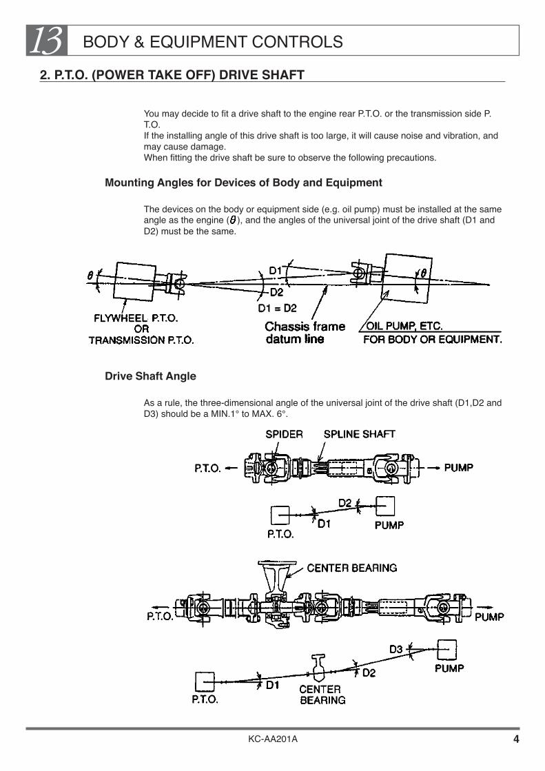
BODY & EQUIPMENT CONTROLS13
KC-AA201A 4
2. P.T.O. (POWER TAKE OFF) DRIVE SHAFT
You may decide to fit a drive shaft to the engine rear P.T.O. or the transmission side P.T.O. If the installing angle of this drive shaft is too large, it will cause noise and vibration, and may cause damage. When fitting the drive shaft be sure to observe the following precautions.
Mounting Angles for Devices of Body and Equipment
The devices on the body or equipment side (e.g. oil pump) must be installed at the same angle as the engine ( ), and the angles of the universal joint of the drive shaft (D1 and D2) must be the same.
Drive Shaft Angle
As a rule, the three-dimensional angle of the universal joint of the drive shaft (D1,D2 and D3) should be a MIN.1° to MAX. 6°.

BODY & EQUIPMENT CONTROLS13
KC-AA201A 5
Length of Drive Shaft
To keep vibration during driving to a minimum, HINO recommend that the drive shaft should be no longer than the values shown in the table below. If you must make the shaft longer than the values shown in the table, fit a central bearing to avoid excessive vibration.
BODY & EQUIPMENT CONTROLS13
KC-AA201A 6
3. ENGINE CONTROLS FOR BODY OR EQUIPMENT
Installation of Engine Accelerator
Engine accelerator for body control may be provided at left side of the cab rear arch as an optional equipment.
Should more detailed date or information with regard to engine accelerator for body control be needed, consult authorized Hino distributor.
Engine accelerator which will be equipped as an optional equipment of cargo, dump and mixer, etc. are described in next pages.
Exact details of engine accelerator, see the Body Mounting Manual for the respective model series.
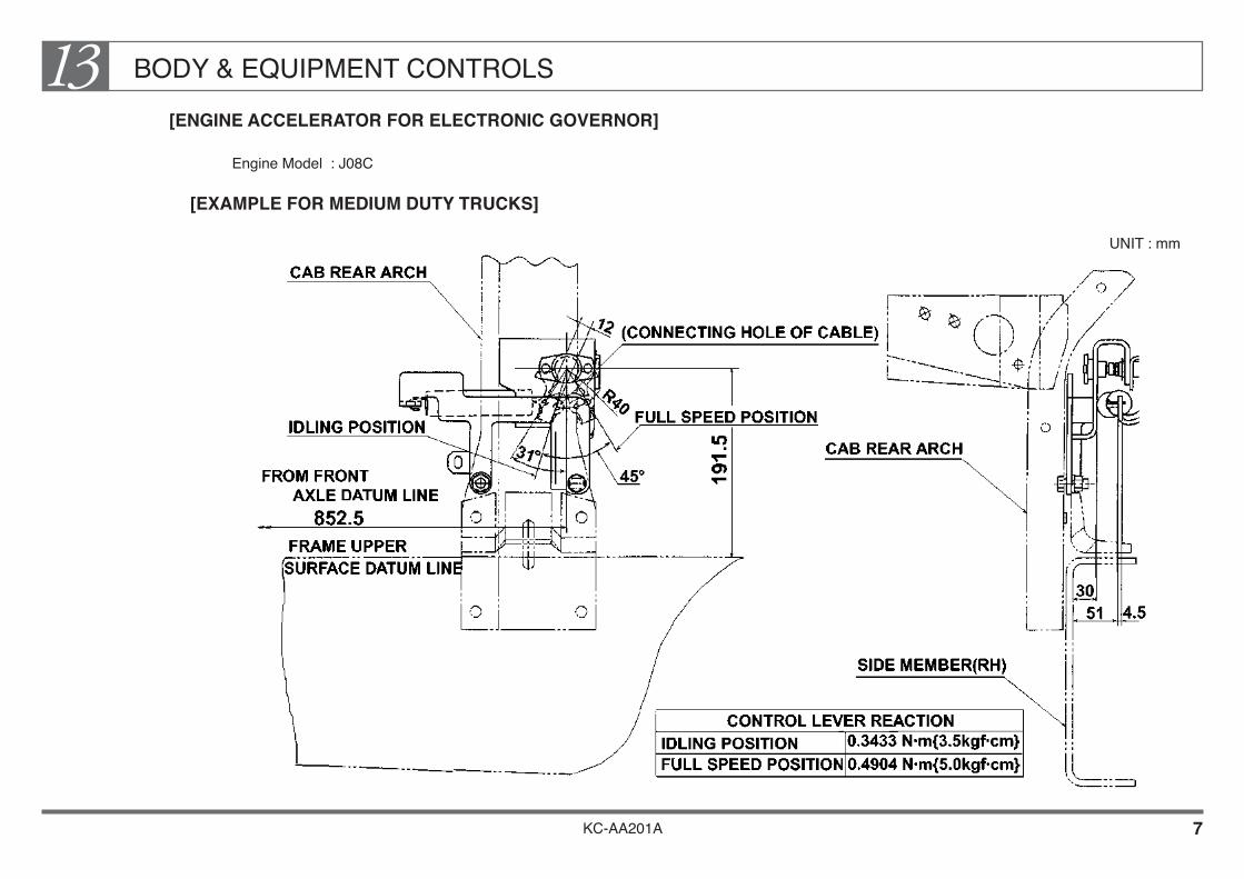
KC-AA201A 7
BODY & EQUIPMENT CONTROLS13[ENGINE ACCELERATOR FOR ELECTRONIC GOVERNOR]
Engine Model : J08C
[EXAMPLE FOR MEDIUM DUTY TRUCKS]
UNIT : mm

BODY & EQUIPMENT CONTROLS13
KC-AA201A 8
[ENGINE ACCELERATOR FOR MECHANICAL GOVERNOR]
Engine Model : J08C
[EXAMPLE FOR MEDIUM DUTY TRUCKS]
UNIT:mm

BODY & EQUIPMENT CONTROLS13
KC-AA201A 9
[HOW TO INSTALL ENGINE ACCELERATOR FOR BODY OR EQUIPMENT]
(ELECTRONIC GOVERNOR ONLY)
Be sure to provide the body controller with the full speed stopper for controlling the stroke of the sensor. In that case, adjust the body side stroke stopper in such a way that the body side stopper comes in contact earlier than the sensor side stopper. The standard for adjustment is 1 mm clearance between the sensor side lever and stopper under the condition that the body side lever touches the stopper. (See the following illustration.)• Be sure to set the sensor lever that sensor lever should be contacted with idling
stopper by adjusting body control lever while body or equipment do not operate (while vehicle is driving).
• The clearance indicated for the stroke stopper of accelerator stopper is just for reference. If the sensor side stopper comes into contact earlier, a forcible stress will be imposed on the sensor shaft and it may result in the damage of the part in cause. Moreover, if sensor lever do not came into contact with idling stopper, may result in a bad condition of the engine while vehicle to be driving.
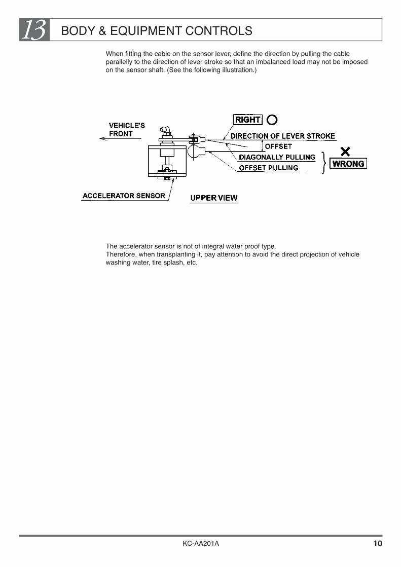
BODY & EQUIPMENT CONTROLS13
KC-AA201A 10
When fitting the cable on the sensor lever, define the direction by pulling the cable parallelly to the direction of lever stroke so that an imbalanced load may not be imposed on the sensor shaft. (See the following illustration.)
The accelerator sensor is not of integral water proof type. Therefore, when transplanting it, pay attention to avoid the direct projection of vehicle washing water, tire splash, etc.
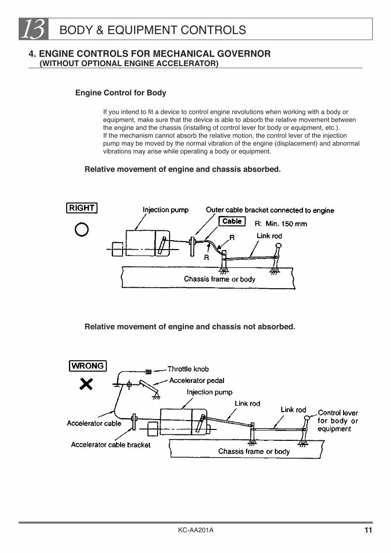
BODY & EQUIPMENT CONTROLS13
KC-AA201A 11
4. ENGINE CONTROLS FOR MECHANICAL GOVERNOR (WITHOUT OPTIONAL ENGINE ACCELERATOR)
Engine Control for Body
If you intend to fit a device to control engine revolutions when working with a body or equipment, make sure that the device is able to absorb the relative movement between the engine and the chassis (installing of control lever for body or equipment, etc.). If the mechanism cannot absorb the relative motion, the control lever of the injection pump may be moved by the normal vibration of the engine (displacement) and abnormal vibrations may arise while operating a body or equipment.
Relative movement of engine and chassis absorbed.
Relative movement of engine and chassis not absorbed.

BODY & EQUIPMENT CONTROLS13
KC-AA201A 12
5. P.T.O. CONTROL (TRANSMISSION SIDE P.T.O.)
Installation of P.T.O. Control Cable
When only P.T.O. control lever in the cab is installed, be sure to install control cable on body manufacturer's responsibility according to the manner in described with following example process. For details, see the Body Mounting Manual for the respective model series.
[EXAMPLE FOR MEDIUM DUTY DUMP TRUCKS]

BODY & EQUIPMENT CONTROLS13
KC-AA201A 13
RECOMMENDED INSTALLATION LAYOUT OF P.T.O. CONTROL CABLE
[EXAMPLE FOR MEDIUM DUTY DUMP TRUCKS]
Details of each model, see the Body Mounting Manual for the respective model.

KC-AA201A
Chapter 14PAINTING
1. TOP COAT PAINTING •••••••••••••••••••••••••••••••••••••••••• 1 2. PRECAUTION OF TOP COAT PAINTING
FOR CAB •••••••••••••••••••••••••••••••••••••••••••••••••••••• 2 3. HANDLING OF LAMINATED WINDSHIELD •••••••••••••• 4 4. PRECAUTIONS FOR FITTING AND STORING
THE CAUTION PLATE •••••••••••••••••••••••••••••••••••••• 5

PAINTING14
KC-AA201A 1
1. TOP COAT PAINTING
Take a care to the following points, when required to repaint it by a customer.
Sanding
When repainting, perform to sand the original coat carefully not to be left any part no-sanded, in order to improve the adhesion of top coat paint. And, never remove off sealant, adhesive agent at connecting parts of the metal sheet.
[Sanding surface]
How to Choose Top Coat Paint
When painting on the metal parts Hino recommends urethane-type, natural air drying paint to be used, which have superior characteristics as in painting finish quality, color fade-out, comparing with lacquer-type paint. The top coat should be at least 30 µ thick.
When painting on the resin parts• Hino recommends paint for the resin parts to be used, which is best matched to the
characteristics of the resin parts (step rubber, front-grill, front garnish, etc.) and also, can prevent to lowering the shock resistant force at low temperature.
• Then, Avoid to paint backside of the resin parts as its shock resistant force lowers further down with the both side to be painted, of the resin parts.
• Cab step, made of polypropylene material, can not be painted.

PAINTING14
KC-AA201A 2
2. PRECAUTION OF TOP COAT PAINTING FOR CAB
Cautions for Cab Painting
When painting the cab, take a caution to the following points, other than above.
The place and parts to be omitted from painting for cab and mounting body as well as adhesion of all kinds of oil:• Various kinds of the ornaments, marks.• Various kinds of caution plates, labels.• Relating equipments and parts to the brake as well as a brake hose.• Various types of rubber hoses.• Electrical wiring, connectors, electrical lamps, electrical switch, relating equipments and
parts.• Back-up buzzer, noise emitting hole of electric horn.• Rubber and plastic parts of cab, engine, chassis suspension and steering system.• Rubber hose for cab-tilt, piston rod of the cylinder for cab-tilt. (The vehicle with a
hydraulic cab-tilt, driven by an electrical motor)• Batteries• Wiper blade, washer nozzle.• Installing surface of disc to the disc wheel. (Including the hub to be contacted and
contacting surface of drum, disc wheel as well as contacting surface of hub nuts.) Then, when stained paint to the inner part of the cab, cleaning it with a neutral detergent, do not use gasoline or thinner.
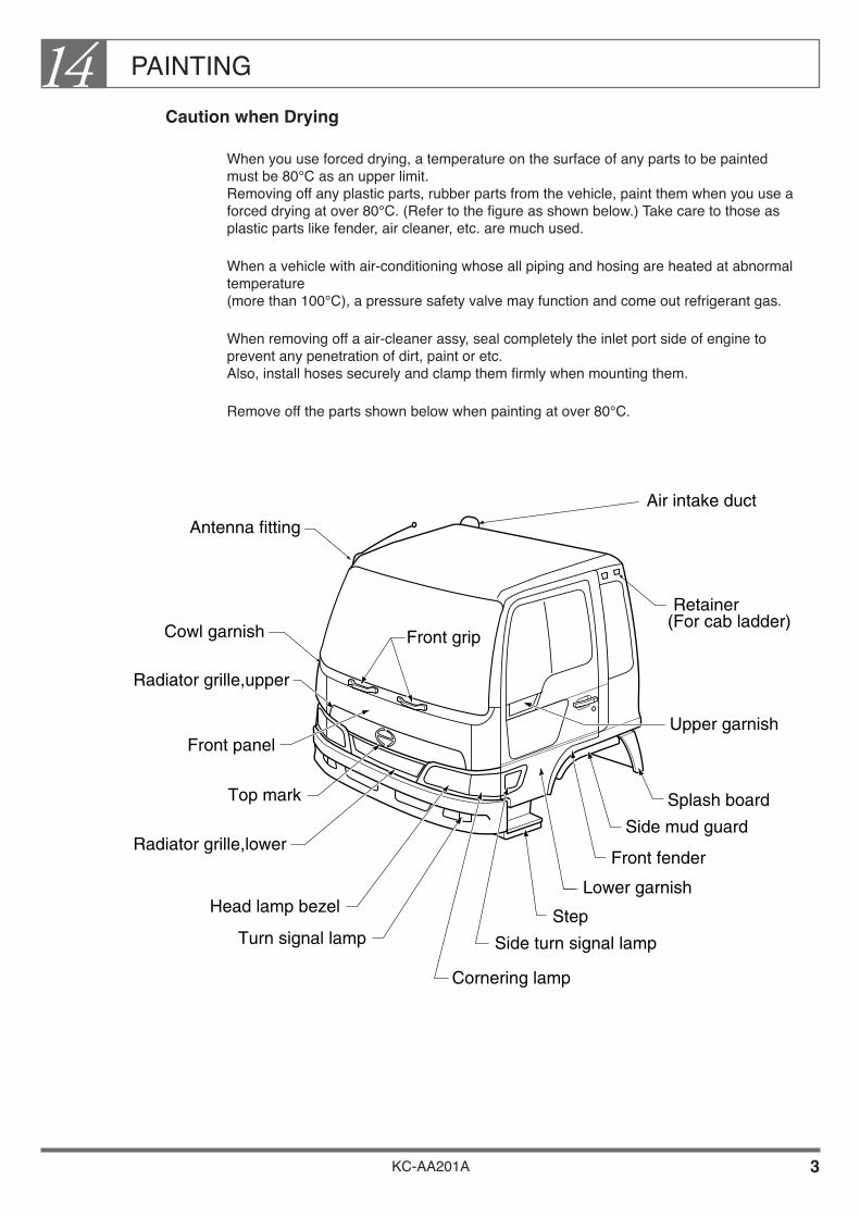
PAINTING14
KC-AA201A 3
Caution when Drying
When you use forced drying, a temperature on the surface of any parts to be painted must be 80°C as an upper limit. Removing off any plastic parts, rubber parts from the vehicle, paint them when you use a forced drying at over 80°C. (Refer to the figure as shown below.) Take care to those as plastic parts like fender, air cleaner, etc. are much used.
When a vehicle with air-conditioning whose all piping and hosing are heated at abnormal temperature (more than 100°C), a pressure safety valve may function and come out refrigerant gas.
When removing off a air-cleaner assy, seal completely the inlet port side of engine to prevent any penetration of dirt, paint or etc. Also, install hoses securely and clamp them firmly when mounting them.
Remove off the parts shown below when painting at over 80°C.
Cowl garnish
Radiator grille,upper
Radiator grille,lower
Top mark
Front panel
Head lamp bezel
Turn signal lamp
Cornering lamp
Side turn signal lamp
Step
Lower garnish
Upper garnish
Side mud guard
Front fender
Splash board
Front grip
Antenna fitting
Air intake duct
Retainer(For cab ladder)

PAINTING14
KC-AA201A 4
3. HANDLING OF LAMINATED WINDSHIELD
A laminated glass is produced in such order that polyvinyl butyral film is inserted between 2 glasses and pressed with heat. Under driving general condition, there is no problem. But under a hot temperature and a high moisture when painting, intermediate film is fallen off or such defective occur as foaming may be caused. Therefore, a special caution needs to be taken.
Caution when Painting
There is no problem when you use a natural drying. But when a forced drying is used with infrared ray lamp, etc., be sure that the drying should be implemented within 30 minutes at less than 120°C. When drying at the temperature of more than 120°C, remove off the windshield glass or cover over the glass with something so that the temperature on the glass surface should not go up more than 120°C.
How to Identify the Laminated Glass.
JIS and Manufacturer Marks are specified at the left bottom of the windshield as shown in the following figure. You can identify it with the specified mark as the mark LP or LS is specified at the underneath of JIS mark in case of the laminated glass. (Partial tempered glass is specified by Z.)

PAINTING14
KC-AA201A 5
4. PRECAUTIONS FOR FITTING AND STORING THE CAUTION PLATE
How to Stick It
Stick the caution plate to a dry place which is free from dust and dirt after the paint has completely dried up.
Clean your hand and don't use cotton work gloves, etc..
Completely remove water, oil, dust, etc. from the surface to stick (surface of cab) with ethyl alcohol if they are found remaining there.
When the temperature is less than 10°C, warm up the surface to stick as well as the caution plate with warm wind of more than 20°C before sticking the caution plate.
After sticking the caution plate, press it with a roller, etc., with a force of approximately 49 N/cm2 {5 kgf/cm2 }.
Remove liner paper (backing paper) just before using it.
When air remains inside, make a tiny hole with a needle or a cutter knife and press it out with your fingers from the bubble area.
How to Store It
When storing the caution plate, select a dry place with an ambient temperature (of 20 to 25°C) and without dust, dirt and stain. Also, store the caution plate at a flat place such as a shelf, etc., and do not place anything on it.
Other Precautions for the Caution Plate
As the caution plate is made from vinyl chloride, it is thin, soft and easily extendible. Therefore, take utmost care for handling it.
When removing the caution plate, etc., be careful not to damage the painted surface with a sharp knife, etc. On the other hand, removal of the caution plate can be done more easily by pulling the caution plate in perpendicular direction to the sticking surface while heating it with a hair dryer.
Do not throw the caution plates away but keep them together to compare with new caution plates and to prevent mixing up with the new ones.

KC-AA201A
Chapter 15VEHICLE INSPECTION & PROTECTION
1. VEHICLE INSPECTION •••••••••••••••••••••••••••••••••••••••• 2 2. HOW TO PROTECT THE VEHICLE AT THE TIME
OF PAINTING AND OF BODY MOUNTING •••••••••••• 7
VEHICLE INSPECTION & PROTECTION15
KC-AA201A 1
We have compiled here important points of the inspection that is required at the time of entry and delivery of the vehicle as well as the protection to carry out on the vehicle when performing painting and body mounting.
The vehicle inspection consists of the following items:
• Standards for twisting of the frame and the difference of Inclination between the left and the right frames at the time of entry to the body or equipment manufacturer.
• Points to pay attention for restoration of the dismounted parts after finishing body mounting and painting.
• Inspection standard of a completed vehicle after finishing body mounting (for reference).
• Check sheet to use for the vehicle in general on delivery (for reference).
We are going to explain you how to protect the vehicle at the time of painting and body mounting for your reference.
Try to well understand the contents of this chapter so that you can deliver the vehicle with quality assurance by correctly inspecting and protecting each item.
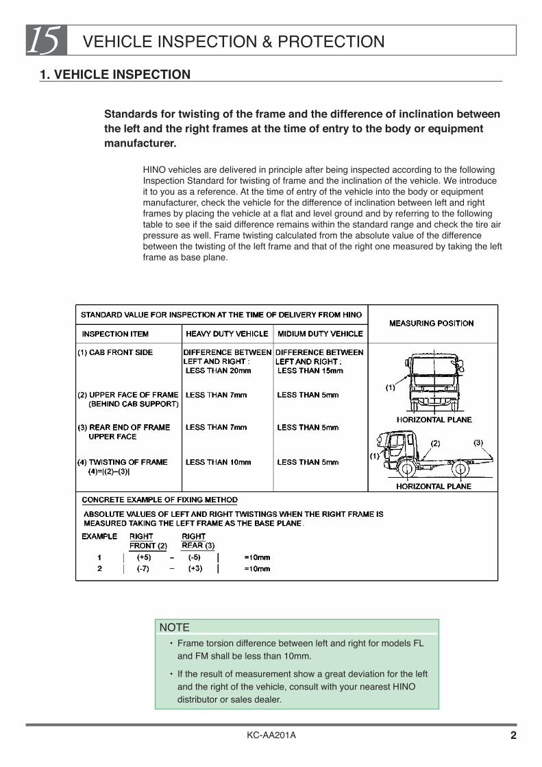
VEHICLE INSPECTION & PROTECTION15
KC-AA201A 2
1. VEHICLE INSPECTION
Standards for twisting of the frame and the difference of inclination between the left and the right frames at the time of entry to the body or equipment manufacturer.
HINO vehicles are delivered in principle after being inspected according to the following Inspection Standard for twisting of frame and the inclination of the vehicle. We introduce it to you as a reference. At the time of entry of the vehicle into the body or equipment manufacturer, check the vehicle for the difference of inclination between left and right frames by placing the vehicle at a flat and level ground and by referring to the following table to see if the said difference remains within the standard range and check the tire air pressure as well. Frame twisting calculated from the absolute value of the difference between the twisting of the left frame and that of the right one measured by taking the left frame as base plane.
NOTE• Frame torsion difference between left and right for models FL
and FM shall be less than 10mm.
• If the result of measurement show a great deviation for the left and the right of the vehicle, consult with your nearest HINO distributor or sales dealer.

VEHICLE INSPECTION & PROTECTION15
KC-AA201A 3
Points to pay attention to the restoration of the dismounted parts after finishing body mounting and painting.
Inspect the vehicle and make correction paying special attention to the following points.
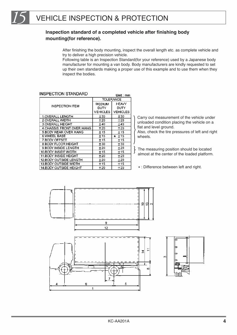
VEHICLE INSPECTION & PROTECTION15
KC-AA201A 4
Inspection standard of a completed vehicle after finishing body mounting(for reference).
After finishing the body mounting, inspect the overall length etc. as complete vehicle and try to deliver a high precision vehicle. Following table is an Inspection Standard(for your reference) used by a Japanese body manufacturer for mounting a van body. Body manufacturers are kindly requested to set up their own standards making a proper use of this example and to use them when they inspect the bodies.
Carry out measurement of the vehicle under unloaded condition placing the vehicle on a flat and level ground. Also, check the tire pressures of left and right wheels.
The measuring position should be located almost at the center of the loaded platform.
: Difference between left and right.*
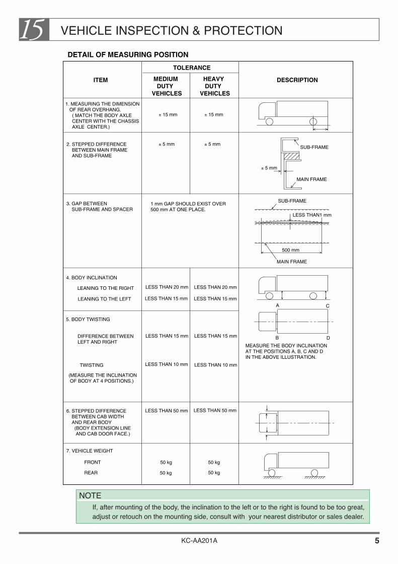
VEHICLE INSPECTION & PROTECTION15
KC-AA201A 5
2. STEPPED DIFFERENCE BETWEEN MAIN FRAME AND SUB-FRAME
3. GAP BETWEEN SUB-FRAME AND SPACER
4. BODY INCLINATION
5. BODY TWISTING
6. STEPPED DIFFERENCE BETWEEN CAB WIDTH AND REAR BODY (BODY EXTENSION LINE AND CAB DOOR FACE.)
SUB-FRAME
SUB-FRAME
LESS THAN1 mm
TOLERANCE
MEDIUM DUTYVEHICLES
HEAVY DUTYVEHICLES
± 5 mm ± 5 mm
± 15 mm ± 15 mm
± 5 mm
1 mm GAP SHOULD EXIST OVER500 mm AT ONE PLACE.
LEANING TO THE RIGHT
LEANING TO THE LEFT
500 mm
A
B
C
D
MAIN FRAME
MAIN FRAME
DIFFERENCE BETWEENLEFT AND RIGHT
TWISTING
(MEASURE THE INCLINATION OF BODY AT 4 POSITIONS.)
7. VEHICLE WEIGHT
FRONT
REAR
MEASURE THE BODY INCLINATIONAT THE POSITIONS A, B, C AND DIN THE ABOVE ILLUSTRATION.
LESS THAN 20 mm LESS THAN 20 mm
LESS THAN 15 mm LESS THAN 15 mm
LESS THAN 15 mm LESS THAN 15 mm
LESS THAN 10 mm LESS THAN 10 mm
LESS THAN 50 mm LESS THAN 50 mm
DETAIL OF MEASURING POSITION
50 kg
50 kg
50 kg
50 kg
ITEM DESCRIPTION
1. MEASURING THE DIMENSION OF REAR OVERHANG. ( MATCH THE BODY AXLE CENTER WITH THE CHASSIS AXLE CENTER.)
NOTE If, after mounting of the body, the inclination to the left or to the right is found to be too great,
adjust or retouch on the mounting side, consult with your nearest distributor or sales dealer.

VEHICLE INSPECTION & PROTECTION15
KC-AA201A 6
Check sheet to use for the vehicle in general at the time of delivery (for reference).
VEHICLE NUMBER :
BODY MANUFACTURER
DATA OFINSPECTION INSPECTOR
ITEM TO CHECK JUDGMENT CONTENTS OF DEFECT CORRECTIONFINISHED
DIS
MO
UN
TIN
G A
ND
RE
MO
UN
TIN
G
CA
BC
AB
CA
BC
AB
CA
BC
AB
CH
AS
SIS
CH
AS
SIS
CH
AS
SIS
CH
AS
SIS
CH
AS
SIS
CH
AS
SIS
· MIRROR STAY, MIRROR,· DOOR SEAL RUBBER,· CAB STEP,· WIPER ARM SHAFT BOOTS,· HINO EMBLEM, FUSE PULLER,· FRONT CORNER PANEL SUB-SEAL,· WIPER BLADE,· OTHERS.
· WRONG RESTORATION (FORGOTTEN TIGHTENING, INSUFFICIENT TIGHTENING TORQUE, PART SHORTAGE, WRONG FITTING, ETC.)
· WRONG RESTORATION (FORGOTTEN TIGHTENING, INSUFFICIENT TIGHTENING TORQUE, PART SHORTAGE, WRONG FITTING, ETC.)
· DOOR SEAL TAPE NOT REMOVED.
· EXHAUST MUFFLER, EXHAUST PIPE,· TAIL PIPE, EXHAUST HANGER,
· TAIL LAMP, PROPELLER GUARD,· HUB NUT, BATTERY TERMINAL,· OTHERS.
RE
TO
UC
HIN
G O
F F
LA
WS
AN
D S
CR
AT
CH
ES
· INNER TRIM,· CENTER CONSOLE COVER,
ROOF TRIM,
· DOOR TRIM,· METERS & INSTRUMENTS
SEATS, FLOOR,
· FENDER GARNISH,· BODY ACCESSORIES, (WHEEL STOPPER, STC HANDLE, PAINT CAN,ETC.) · REAR WINDOW, FRONT GRILLE,· SPLASH BOARD, OTHERS.
· FLAWS AND SCRATCHES CAUSED BY HANDLING.· FLAWS AND SCRATCHES CAUSED BY BODY ACCESSORIES.· SPOTTER DAMAGE OF REAR WINDOW.
· AIR CLEANER, BATTERY COVER,· RELAY BOX, FRONT BUMPER,· OTHERS.
· FLAWS AND SCRATCHES DUE TO HANDLING.
ST
AIN
BY
PA
INT · BED, TRIMS, FENDER,
· OTHERS.
· STAIN BY PAINT.
· CAUTION PLATE STAINED BY PAINT, (AIR DRYER, SUB-STARTER, CAB-TILT CAUTION PLATE, ETC.)· PS TANK,· OTHERS.
· CAUTION PLATES CANNOT BE READ DUE TO STAIN BY PAINT
· EXHAUST HANGER CLAMP,
FU
NC
TIO
NA
LC
OM
PO
NE
NT
S
· BACK MIRROR, WINKER LAMPS,· POWER WINDOW,· CIGAR LIGHTER, CAB-TILT,· SIDE MARKER LAMPS,· OTHERS.
· BAD FUNCTIONING DUE TO NON-CONNECTION OF HARNESS.· CAB-TILT BUZZER DOES NOT BEEP. (DISCONNECTION OF COUPLER ON CROSSMEMBER NO.1.)
· ENGINE REVOLUTION,· SIDE MARKER LAMPS, (ON BODY SIDE)· OTHERS.
· POOR CONNECTION OF BODY ACCELERATOR CABLE.
· BO
DY
UP
PE
R S
TR
UC
TU
RE · CLEARANCE BETWEEN BODY
UPPER STRUCTURE PARTS AND CAB.· OTHERS.
· INTERFERENCE BETWEEN LOADING PLATFORM AND CAB-TILT.
· WORKING LIGHT,· BODY UPPER STRUCTURE ACCELERATOR CABLE,
· UPPER STRUCTURE LAMPS, (MARKER LAMPS, SIDE WINKER LAMPS,ETC.)· SIDE GUARD,
·LAMPS OF UPPER STRUCTURE DO NOT LIGHT.· INTERFERENCE BETWEEN UPPER STRUCTURE AND CHASSIS PARTS OR INSUFFICIENT CLEARANCE, INTERFERENCE BETWEEN SIDE GUARD AND TAIL PIPE.
OT
HE
RS
· LEAVING BEHIND OF STAIN GUARD CLOTH AGAINST PAINT.
· CLOTH LEFT BEHIND ON THE ENGINE.· PAPER ON THE MANIFOLDS.· MISSING OF BRAKE BOOSTER AIR BLEEDER CAP.
OTHERS.
ITEM
· OUTRRIGER,

VEHICLE INSPECTION & PROTECTION15
KC-AA201A 7
2. HOW TO PROTECT THE VEHICLE AT THE TIME OF PAINTING AND OF BODY MOUNTING
In order to avoid eventual damage of the cab, carry out your work by observing the following items for protection.
