ho-yeon ahn , dong-wook oh and *yong-joo lee3) · of horizontal subgrade reaction is constant....
TRANSCRIPT

Behaviour of vertically and horizontally loaded pile and adjacent ground affected by tunnelling
Ho-Yeon Ahn1), Dong-Wook Oh2) and *Yong-Joo Lee3)
1), 2),3) Department of Civil Engineering, Seoul National University of Science and
Technology, Seoul 01811, Korea 3)
ABSTRACT
Recent occurrences of earthquakes in Korea have increased the importance of considering how horizontal loads affect foundation structures as a result of wind and dynamic impact. However, to date, there are few studies on tunnelling-induced behaviour of ground and pile structures subjected to horizontal and vertical loads at the same time. In this research, therefore, behaviour of ground and single piles due to tunnelling were investigated through a laboratory model test. Three cases of horizontal loads were applied to the pile top. In addition, a numerical analysis was carried out to analyse and compare with the results from the laboratory model test. 1. INTRODUCTION As the construction of high-rise buildings and occurrences of earthquakes continue to increase, the importance of horizontal loads are gaining more attention. The bearing capacity of a single pile according to the horizontal load is determined by load tests and analytical methods. A variety of analytical methods have so far been proposed. Chang (1937) proposed an equation for the bending deflection of piles which are supported on elastic foundations. This method is only possible when the coefficient of horizontal subgrade reaction is constant. Matlock and Reese (1960) suggested the p-y curve of the relationship between pile displacement and subgrade reaction. This method can be considered as nonlinear in terms of ground behaviour. Equations of the pile bending moment and ground stiffness was put forward by Broms (1964) who proposed a design method to calculate the stress-strain of the pile to assume the failure mode, depending upon pile length and soil conditions. Also, Matlock (1970) assumed that the subgrade reaction at a point occurs according to the displacement of the pile at that point only. However, there is a lack of research on the behaviour of pile and ground
1)
Master 2)
PhD student 3)
Professor

depending on the horizontal load. Therefore, the authors analysed the behaviours of pile subjected to vertical, horizontal loads as well as ground deformation induced by tunnelling. Tunnelling is very useful and widely used to solve environment and transportation problems resulting from population growth in urban areas. Tunnelling is represented by volume loss, as suggested by Atkinson and Mair (1981). It is controlled through water inflow and outflow for the model tunnel device (Lee, 2014) and 5% of volume loss is applied (Atkinson, 2007). Allowable vertical and horizontal loads are estimated by the static pile load test. Settlements of pile and ground surface, as well as the pile axial force resulting from tunnelling in the laboratory model test, are compared using the Finite Element Analysis (FEA). 2. LABORATORY MODEL TEST Vertical and horizontal loads are applied to the pile and a tunnel is excavated under the pile. The behaviours of the pile and adjacent ground and the pile axial force are analysed for 6 cases according to various horizontal offsets between the tunnel crown. 2.1 Pile calibration Before the laboratory model test, the pile calibration is performed using UTM (Fig. 1(a)).
(a) UTM (b) Location of the strain gauges Fig. 1. Pile calibration
In order to measure the load and strain, 6 strain gauges are attached to the pile, located from top to bottom on the left and right sides of the pile (Fig. 1(b)). The results of each strain gauge from calibration test are shown in Fig 2.

Fig. 2. Results of the pile calibration
Fig. 3. P-S curve Fig. 4. P-Y curve
(a) Case 1 (0.0D) (b) Case 2 (Case 1.0D)
Fig. 5. 6 cases

Table 1. Cases of laboratory model test
Allowed horizontal load (kN)
34% 67% 100%
Horizontal offset
0.0D Case 1-1 Case 1-2 Case 1-3
1.0D Case 2-1 Case 2-2 Case 2-3
2.2 Selection of the loads The allowable vertical load is obtained from the load-settlement relationship (Fig. 3) using the LCM (load control method) and that is defined as 0.323 kN by ultimate vertical load of safety factor 3.0. The ultimate horizontal load is 0.106 kN for the pile load test and safety factor is 3.0. which is the as same vertical load. The allowable horizontal load is 0.0353 kN (Fig. 4). This is divided into 3 cases for horizontal loads viz., 34%, 67% and 100% of the allowed horizontal load. The horizontal load and the horizontal offset between the pile and tunnel are classified into 6 cases (Table 1, Fig. 5). 2.3 Results of the laboratory model test As the horizontal load increases, horizontal displacement also increases. Figure 6 shows that as the offset between the pile and tunnel centre increases, the pile becomes more influenced by the horizontal load. Settlements of the pile and ground surface due to tunnelling (VL=5%) are illustrated in Fig. 7. In the x-axis, 0 represents the location of the pile and other numbers show the distance of the measurement points for the ground surface settlement. Vertical displacement of the pile and ground surface has a similar tendency with the Gaussian curve, which is mentioned by Atkinson (2007) regarding the shape of ground surface deformation due to tunnelling in greenfield condition. The pile settlement for case 1 is larger than in case 2. This means the pile is more affected by tunnelling. Figure 8 shows the change of pile axial force due to development of volume loss from 0% to 5%. As a result, the change of pile axial force becomes greater due to the increase of volume loss.
Fig. 6. Horizontal displacement (VL=5%)

(a) Case 1 (b) Case 2
Fig. 7. Settlement of the pile and ground surface (VL=1.5~5.0%)
(a) Case 1-3 (b) Case 2-3
Fig. 8. Change of pile axial force due to development of volume loss (VL=1.5~5.0%) 3. FINITE ELEMENT ANALYSIS 3.1 Material properties The Finite Element Analysis (FEA) programme is simulated in the same situation with the laboratory model test. The properties of the soil are based on the results of the relative density (loose sand) conducted in the laboratory model test (Kim, 2012). The pile is applied to pure aluminium properties and the interface strength reduction factor (Rinter) (Lee, 2013). The tunnelling is simulated by ground volume loss. The properties for numerical analysis are shown in Table 2, and modelling for each case is illustrated in Fig. 9.
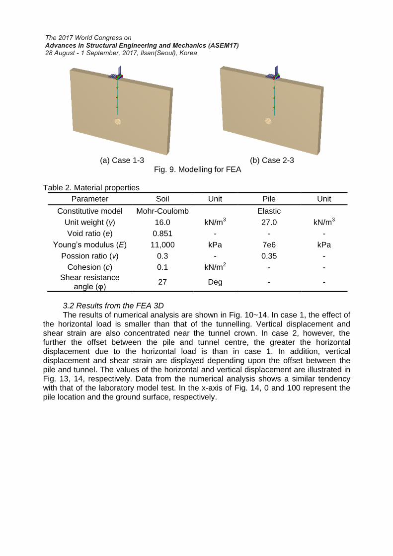
(a) Case 1-3 (b) Case 2-3
Fig. 9. Modelling for FEA Table 2. Material properties
Parameter Soil Unit Pile Unit
Constitutive model Mohr-Coulomb Elastic
Unit weight (γ) 16.0 kN/m3 27.0 kN/m3
Void ratio (e) 0.851 - - -
Young’s modulus (E) 11,000 kPa 7e6 kPa
Possion ratio (ν) 0.3 - 0.35 -
Cohesion (c) 0.1 kN/m2 - -
Shear resistance angle (φ)
27 Deg - -
3.2 Results from the FEA 3D
The results of numerical analysis are shown in Fig. 10~14. In case 1, the effect of the horizontal load is smaller than that of the tunnelling. Vertical displacement and shear strain are also concentrated near the tunnel crown. In case 2, however, the further the offset between the pile and tunnel centre, the greater the horizontal displacement due to the horizontal load is than in case 1. In addition, vertical displacement and shear strain are displayed depending upon the offset between the pile and tunnel. The values of the horizontal and vertical displacement are illustrated in Fig. 13, 14, respectively. Data from the numerical analysis shows a similar tendency with that of the laboratory model test. In the x-axis of Fig. 14, 0 and 100 represent the pile location and the ground surface, respectively.

(a) Case 1-3 (b) Case 2-3
Fig. 10. Horizontal displacement contours
(a) Case 1-3 (b) Case 2-3
Fig. 11. Vertical displacement contours
(a) Case 1-3 (b) Case 2-3
Fig. 12. Shear strain contours

Fig. 13. Horizontal displacement (VL=5%)
Fig. 14. Settlements of pile and ground surface (VL=5%)
4. COMPARISON OF DATA Results from the laboratory model test and numerical analysis are compared. Comparisons of settlements and pile axial force are displayed in Fig. 15~17. All the results from the laboratory model test are higher than those of the numerical analysis. In Fig. 18, the greater the horizontal load, the bigger horizontal displacement is also.
Fig. 15. Comparison of horizontal displacement When the pile is located above the tunnel, settlement occurs and decreases towards the ground surface. Also, the further the offset between the pile and tunnel centre is, the more horizontal displacement increases; however, settlement does not. Figure 18 shows the axial force of the pile, which is measured according to the location of the strain gauges. The figures on the left are for FEA 3D, with (-) and (+) representing compression and tension, respectively. The graphs on the right display the value of the laboratory model test. Here, (-) shows tension and (+) represents compression. The results have a similar tendency.

(a) Case 1 (b) Case 2
Fig. 16. Comparison of pile settlement
(a) Case 1 (b) Case 2 Fig. 17. Comparison of pile settlement

(a) pile axial force for FEA and model test (case 1)
(b) pile axial force for FEA and model test (case 2) Fig. 18. Comparison of axial force
5. CONCLUSION In this study, tunnelling under the pile is subjected to both the vertical and the horizontal loads. The behaviour of the pile and adjacent ground are analysed according to the laboratory model test and the FEA. Overall, the results have a similar tendency.
1) The further the offset between the pile and the tunnel centre is, the pile is increasingly affected by horizontal loads. Thus, the effect of tunnelling is large when the pile is located above the tunnel (case 1).
2) The larger the horizontal loads applied to the pile is, the horizontal displacement of the pile also increases and the settlement of the pile and ground surface decreases.
3) When the horizontal load is applied to the pile and tunnelling, compression occurs above the pile and tension takes place under the pile. When the horizontal load is small (34%), the settlement of the pile is large because the area under the pile is subjected to tension due to the tunnelling.
As a result, the load applied to the pile and the horizontal offset between the pile and tunnel are important factors in tunnelling.
ACKNOWLEDGEMENT This study was supported by basic science and engineering research program through the National Research Foundation of Korea (NRF-2013R1A1A2005101). REFERENCES Arunkumar, S. and Ayothiraman, R. (2010), “Effect of vertically loaded pile on existing
urban tunnel in clay”, Indian Geotechnical Conference. Atkinson, J.H. and Mair, R.J. (2007), “The mechanics of soils and foundations”, Taylor
& Francis, Second edition, pp. 404-406. Bae, J.S. and Kim, S.H. (2008), “Behaviour of back ground of laterally loaded single
pile”, Journal of Korean Geotechnical Society, Vol. 24(8), pp. 53-60. Choi, I.G. and Park, Y.M. (2006), “Geotechnical engineering”, Goomibook, pp. 491-500. Das, B.M. (2010), “Principles of geotechnical engineering”, Cengage learning, Seven
edition, pp. 55. Kim, Y.S., Ko. H.W., Kim, J.H. and Lee, J.G. (2012), “Dynamic deformation
characteristics of Joomunjin standard sand using cyclic triaxial test”, Journal of Korean Geotechnical Society, Vol. 28(12), pp. 53-64.
Kong, S.M. (2015), “A study on embedded pile behavior at tunnel crown area due to tunnelling”, MSc thesis, Seoul National University of Science and Technology, Seoul.
Kong, S.M. and Lee, Y.J. (2016), “A study on soil behavior due to tunnelling under embedded pile using close range photogrammetry”, Journal of Korean Tunnel Underground Space Association, Vol. 18(4).
Kwon, H.J., Kim, D.S., Park, J.B. and Jung, S.K. (2011), “Foundation Engineering”, Goomibook, Second edition, pp. 204-210. (in Korean)
Lambe, T.W. and Whitman, R.V. (1979), “Soil Mechanics”, SI version, John Wiley & Son, pp. 31.
Lee, J.H. (2014), “Model tunnel excavation using close range photogrammetric technique for tunnel roof reinforcement”, MSc thesis, Seoul National University of Science and Technology, Seoul.
Lee, J.M. (2013), “Investigation of bored pile behavior according to interface properties”, MSc thesis, Seoul National University of Science and Technology, Seoul.
Lee, Y.J., Basseett, R.H. (2006), “Application of a photogrammetric technique to a model tunnel”, Tunnelling and underground Space Technology, Vol. 21, pp. 79-95.
Meyer, B.J. and Reese, L.C. (1979), “Analysis of single piles under lateral loading”, Texas State Department of highways and Public Transportation.
Park, K.H. (2010), “Lateral behavior of driven piles subjected to cyclic lateral loads in sand”, Journal of Korean Geotechnical Society, Vol. 26(12), pp. 41-50.
PLAXIS AE (2013), Reference manual, pp. 1-307. Reese, L.C. and Van Impe, W.F. (2011), “Single piles and pile groups under lateral
loading”, CRC Press Taylor & Francis Group, Second edition, pp. 205-212.