hoisting equipment - cmco€¦ · hoisting equipment for a safe lifting and handling of loads ......
TRANSCRIPT

9
HOISTING EQUIPMENT
8
Hoisting Equipment Table of contents
Page Ratchet lever hoists 14 - 21
Hand chain hoists 22 - 35
Corrosion protection 36
Trolleys & Trolley clamps 35, 37 - 43
Electric & Pneumatic chain hoists 48 - 65
Chains & Accessories 66 - 68
Manual winches 69 - 79
Cable puller & Accessories 80 - 87
Electric & Pneumatic winches 91 - 107
Rack & Pinion jacks 108 - 123
Crane Systems 128 - 139
Power supply 140 - 141
INFO
Please note our user instructions at the beginning of each chapter.
Yale and Pfaff-silberblau hoisting equipment products are reliable and proven equipment renowned world-wide for applications in industry, trade and services. The comprehensive range includes manual and powered hoisting equipment for a safe lifting and handling of loads ranging from 125 kg to 20000 kg. The products feature a long service life as well as easy and quick maintenance or repair. Yale and Pfaff-silberblau hoisting equipment products comply with national and international regulations such as the EC Machinery Directive 2006/42/EC and cor-responding supplements. In order to meet our high quality standard, the devices are subjected to an overload test in the factory and provided with a test certificate and operating instructions with a declaration of conformity or a manufacturer’s declaration.
130
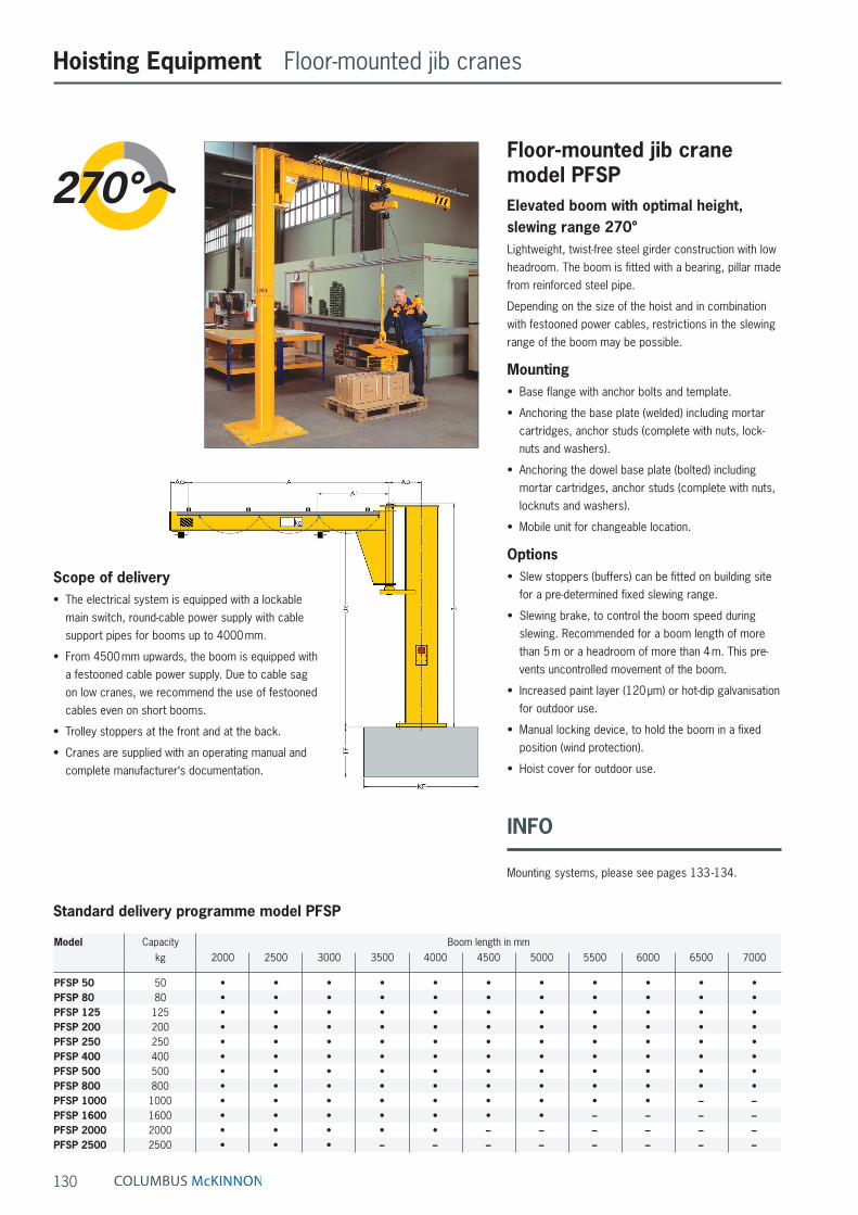
Floor-mounted jib crane model PFSPElevated boom with optimal height, slewing range 270°Lightweight, twist-free steel girder construction with low headroom. The boom is fitted with a bearing, pillar made from reinforced steel pipe.
Depending on the size of the hoist and in combination with festooned power cables, restrictions in the slewing range of the boom may be possible.
Mounting• Base flange with anchor bolts and template.
• Anchoring the base plate (welded) including mortar cartridges, anchor studs (complete with nuts, lock-nuts and washers).
• Anchoring the dowel base plate (bolted) including mortar cartridges, anchor studs (complete with nuts, locknuts and washers).
• Mobile unit for changeable location.
Options• Slew stoppers (buffers) can be fitted on building site
for a pre-determined fixed slewing range.
• Slewing brake, to control the boom speed during slewing. Recommended for a boom length of more than 5 m or a headroom of more than 4 m. This pre-vents uncontrolled movement of the boom.
• Increased paint layer (120 µm) or hot-dip galvanisation for outdoor use.
• Manual locking device, to hold the boom in a fixed position (wind protection).
• Hoist cover for outdoor use.
Hoisting Equipment Floor-mounted jib cranes
Scope of delivery• The electrical system is equipped with a lockable
main switch, round-cable power supply with cable support pipes for booms up to 4000 mm.
• From 4500 mm upwards, the boom is equipped with a festooned cable power supply. Due to cable sag on low cranes, we recommend the use of festooned cables even on short booms.
• Trolley stoppers at the front and at the back.
• Cranes are supplied with an operating manual and complete manufacturer‘s documentation.
Standard delivery programme model PFSP
Model Capacity Boom length in mmkg 2000 2500 3000 3500 4000 4500 5000 5500 6000 6500 7000
PFSP 50 50 • • • • • • • • • • •PFSP 80 80 • • • • • • • • • • •PFSP 125 125 • • • • • • • • • • •PFSP 200 200 • • • • • • • • • • •PFSP 250 250 • • • • • • • • • • •PFSP 400 400 • • • • • • • • • • •PFSP 500 500 • • • • • • • • • • •PFSP 800 800 • • • • • • • • • • •PFSP 1000 1000 • • • • • • • • • – –PFSP 1600 1600 • • • • • • • – – – –PFSP 2000 2000 • • • • • – – – – – –PFSP 2500 2500 • • • – – – – – – – –
INFO
Mounting systems, please see pages 133 -134.
131
Hoisting Equipment Floor-mounted jib cranes
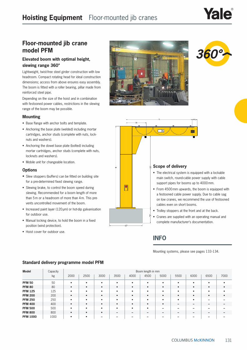
Floor-mounted jib crane model PFMElevated boom with optimal height, slewing range 360°Lightweight, twist-free steel girder construction with low headroom. Compact rotating head for ideal construction dimensions; access from above ensures easy assembly. The boom is fitted with a roller bearing, pillar made from reinforced steel pipe.
Depending on the size of the hoist and in combination with festooned power cables, restrictions in the slewing range of the boom may be possible.
Mounting• Base flange with anchor bolts and template.
• Anchoring the base plate (welded) including mortar cartridges, anchor studs (complete with nuts, lock-nuts and washers).
• Anchoring the dowel base plate (bolted) including mortar cartridges, anchor studs (complete with nuts, locknuts and washers).
• Mobile unit for changeable location.
Options• Slew stoppers (buffers) can be fitted on building site
for a pre-determined fixed slewing range.
• Slewing brake, to control the boom speed during slewing. Recommended for a boom length of more than 5 m or a headroom of more than 4 m. This pre-vents uncontrolled movement of the boom.
• Increased paint layer (120 µm) or hot-dip galvanisation for outdoor use.
• Manual locking device, to hold the boom in a fixed position (wind protection).
• Hoist cover for outdoor use.
Scope of delivery• The electrical system is equipped with a lockable
main switch, round-cable power supply with cable support pipes for booms up to 4000 mm.
• From 4500 mm upwards, the boom is equipped with a festooned cable power supply. Due to cable sag on low cranes, we recommend the use of festooned cables even on short booms.
• Trolley stoppers at the front and at the back.
• Cranes are supplied with an operating manual and complete manufacturer‘s documentation.
Standard delivery programme model PFM
Model Capacity Boom length in mmkg 2000 2500 3000 3500 4000 4500 5000 5500 6000 6500 7000
PFM 50 50 • • • • • • • • • • •PFM 80 80 • • • • • • • • • • •PFM 125 125 • • • • • • • • • • •PFM 200 200 • • • • • • • • • • •PFM 250 250 • • • • • • • • • – –PFM 400 400 • • • • • • • – – – –PFM 500 500 • • • • • • – – – – –PFM 800 800 • • • – – – – – – – –PFM 1000 1000 • • – – – – – – – – –
INFO
Mounting systems, please see pages 133 -134.