hoisting system
TRANSCRIPT

Drilling Engineering 1 Course3rd Ed. , 3rd Experience
1. Hoisting System:A. IntroductionB. The Block & Tackle
a. Mechanical advantage and Efficiencyb. Hook Power
C. Load Applied to the Derrick


Typical hoisting systemThe hoisting system is used
to raise, lower, and suspend equipment in the well (e.g., drillstring, casing, etc).
It is consists of:derrick (not shown)draw works the block-tackle system
fast line (braided steel cable) crown block traveling block dead line (1” to 13/4=3.25”) deal line anchor, storage reel, hook.
Fall 14 H. AlamiNia Drilling Engineering 1 Course (3rd Ed.) 4

The DerrickThe derrick provides the necessary height and
support to lift loads in and out of the well.
The derrick must be strong enough to support the hook load, deadline and fastline loads,
pipe setback load and wind loads.
Derricks are rated by the API according to their height (to handle 2, 3, or 4 joints) and their ability to withstand wind and compressive loads.
Fall 14 H. AlamiNia Drilling Engineering 1 Course (3rd Ed.) 5

The DerrickThe derrick stands
above the derrick floor. It is the stage where several surface
drilling operations occur. At the derrick floor are located
the drawworks, the driller’s console, the driller’s house (or “doghouse”), the rotary table, the drilling fluid manifold, and several other tools to operate the drillstring.
The space below the derrick floor is the substructure. The height of the substructure should
be enough to accommodate the wellhead and BOPs.
doghouse
Fall 14 H. AlamiNia Drilling Engineering 1 Course (3rd Ed.) 6
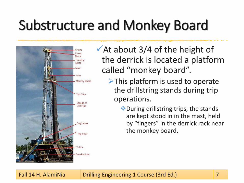
Substructure and Monkey BoardAt about 3/4 of the height of
the derrick is located a platform called “monkey board”. This platform is used to operate
the drillstring stands during trip operations. During drillstring trips, the stands
are kept stood in in the mast, held by “fingers” in the derrick rack near the monkey board.
Fall 14 H. AlamiNia Drilling Engineering 1 Course (3rd Ed.) 7
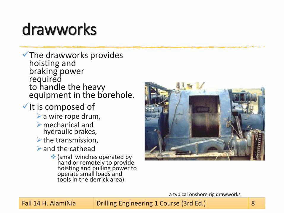
drawworksThe drawworks provides
hoisting and braking power required to handle the heavy equipment in the borehole. It is composed of
a wire rope drum, mechanical and
hydraulic brakes, the transmission, and the cathead
(small winches operated by hand or remotely to provide hoisting and pulling power to operate small loads and tools in the derrick area).
a typical onshore rig drawworks
Fall 14 H. AlamiNia Drilling Engineering 1 Course (3rd Ed.) 8
Reeling in and outThe reeling–in of the drilling line is powered by an electric motor or Diesel engine
the reeling–out is powered by gravityTo control the reeling out,
mechanical brakes and auxiliary hydraulic or magnetic brakes
are used, which dissipates the energy required to reduce the speed and/or stop the downward movement of the suspended equipment.
Fall 14 H. AlamiNia Drilling Engineering 1 Course (3rd Ed.) 9


The Block & TackleFast line
The drilling line coming from the drawworks, called fast line, goes over a pulley system mounted at the top of the derrick, called the crown block,
and down to another pulley system called the traveling block.
block-tackle The assembly of crown block, traveling block and drilling line
The number of lines n of a tackle is twice the number of (active) pulleys in the traveling block.
The last line of the tackle is called dead line and is anchored to the derrick floor, close to one of its legs.
Below and connected to the traveling block is a hook to which drilling equipment can be hung.
Fall 14 H. AlamiNia Drilling Engineering 1 Course (3rd Ed.) 11
block-tackle system calculationsThe block-tackle system provides a mechanical advantage to the drawworks, and reduces the total load applied to the derrick.
We will be interested in calculating the fast line force Ff (provided by the drawworks)
required to raise a weight W in the hook, and the total load applied to the rig and its distribution on the derrick floor.
Fall 14 H. AlamiNia Drilling Engineering 1 Course (3rd Ed.) 12
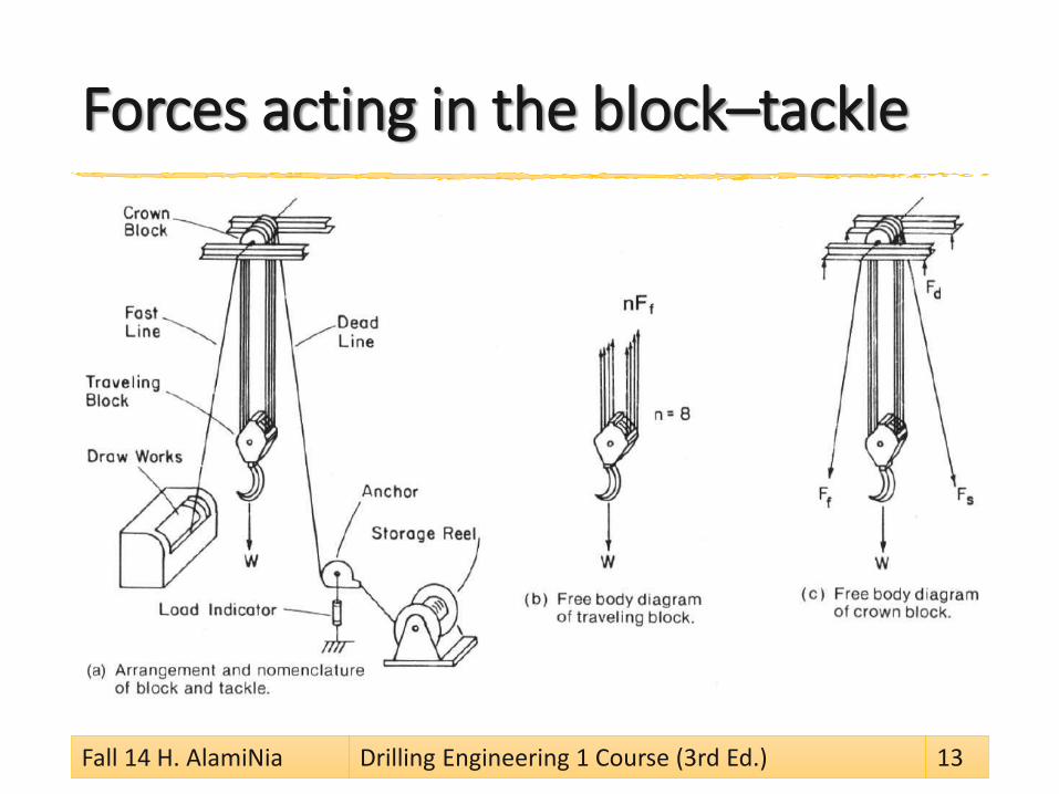
Forces acting in the block–tackle
Fall 14 H. AlamiNia Drilling Engineering 1 Course (3rd Ed.) 13
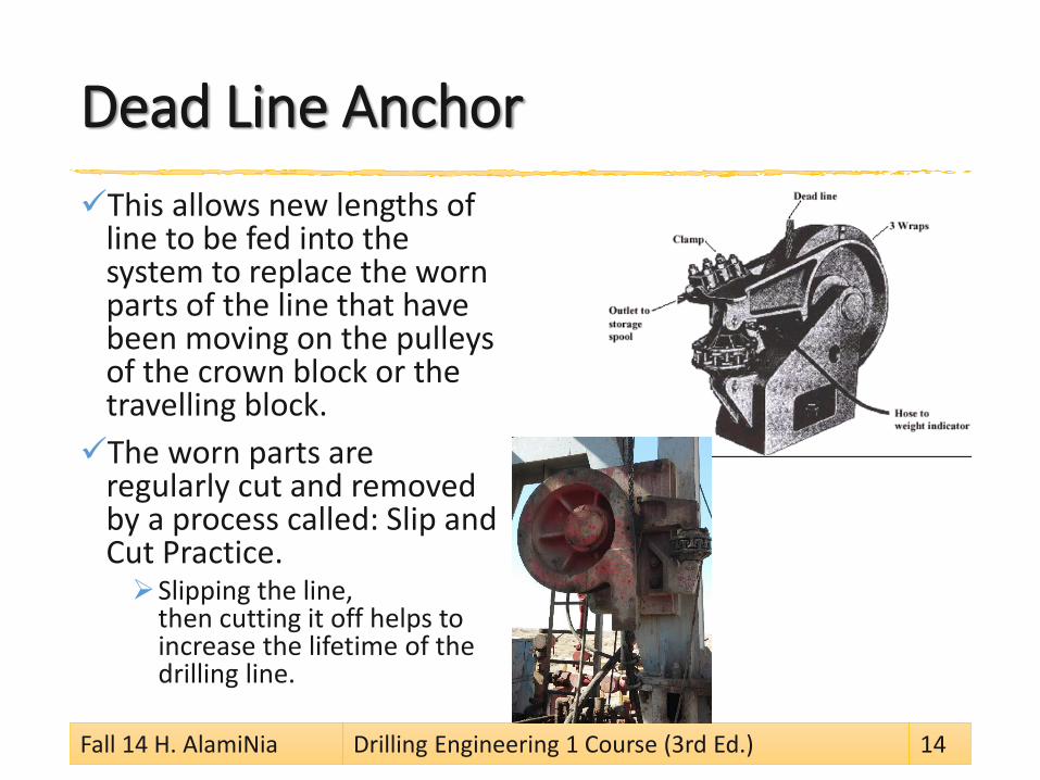
Dead Line AnchorThis allows new lengths of
line to be fed into the system to replace the worn parts of the line that have been moving on the pulleys of the crown block or the travelling block.The worn parts are
regularly cut and removed by a process called: Slip and Cut Practice. Slipping the line,
then cutting it off helps to increase the lifetime of the drilling line.
Fall 14 H. AlamiNia Drilling Engineering 1 Course (3rd Ed.) 14
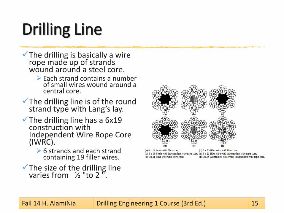
Drilling LineThe drilling is basically a wire
rope made up of strands wound around a steel core. Each strand contains a number
of small wires wound around a central core.
The drilling line is of the round strand type with Lang’s lay. The drilling line has a 6x19
construction with Independent Wire Rope Core (IWRC). 6 strands and each strand
containing 19 filler wires. The size of the drilling line
varies from ½ "to 2 ".
Fall 14 H. AlamiNia Drilling Engineering 1 Course (3rd Ed.) 15

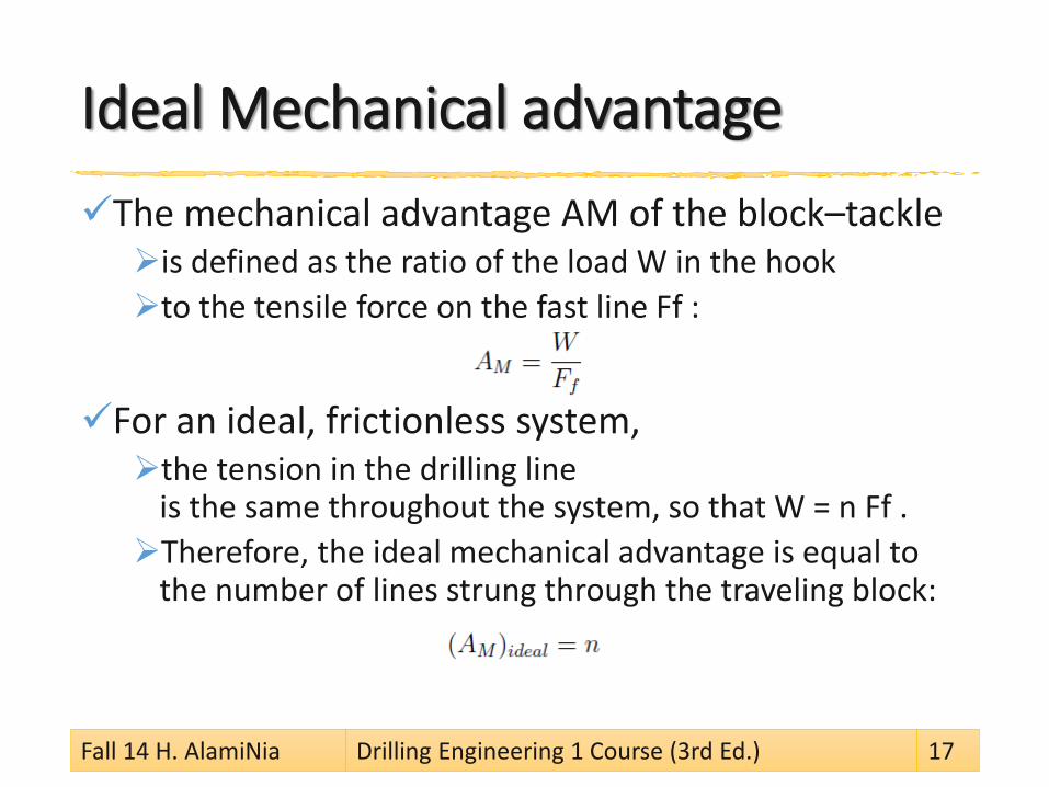
Ideal Mechanical advantageThe mechanical advantage AM of the block–tackleis defined as the ratio of the load W in the hook to the tensile force on the fast line Ff :
For an ideal, frictionless system, the tension in the drilling line
is the same throughout the system, so that W = n Ff . Therefore, the ideal mechanical advantage is equal to
the number of lines strung through the traveling block:
Fall 14 H. AlamiNia Drilling Engineering 1 Course (3rd Ed.) 17
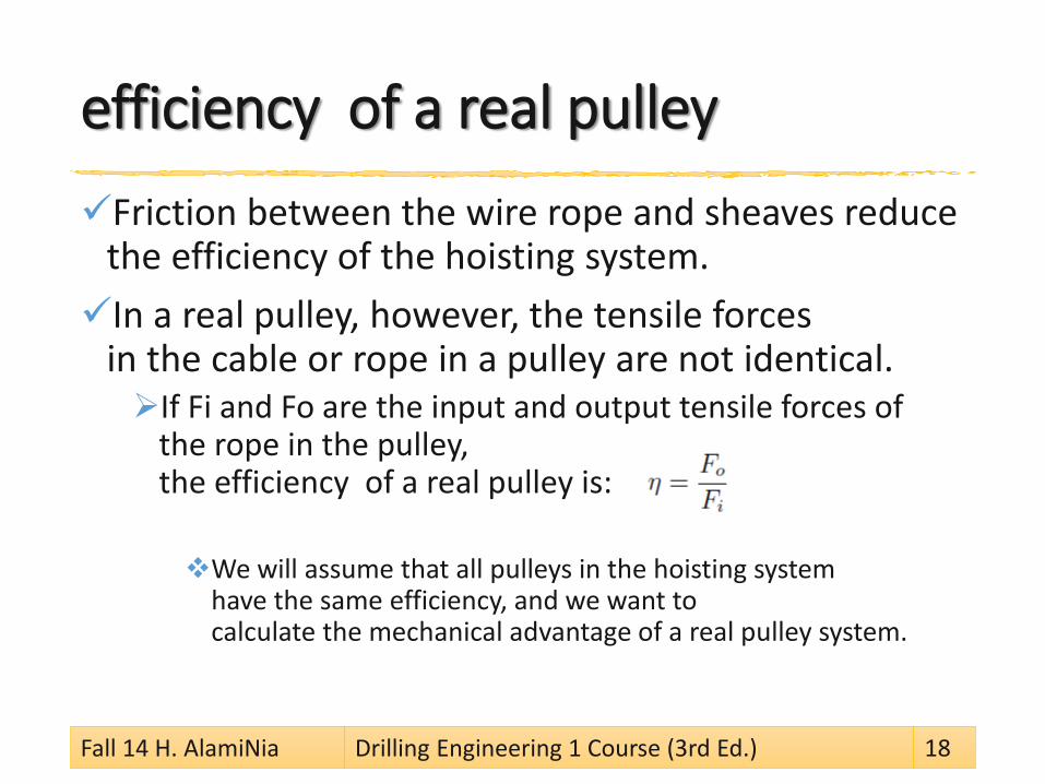
efficiency of a real pulleyFriction between the wire rope and sheaves reduce
the efficiency of the hoisting system.In a real pulley, however, the tensile forces
in the cable or rope in a pulley are not identical. If Fi and Fo are the input and output tensile forces of
the rope in the pulley, the efficiency of a real pulley is:
We will assume that all pulleys in the hoisting system have the same efficiency, and we want to calculate the mechanical advantage of a real pulley system.
Fall 14 H. AlamiNia Drilling Engineering 1 Course (3rd Ed.) 18
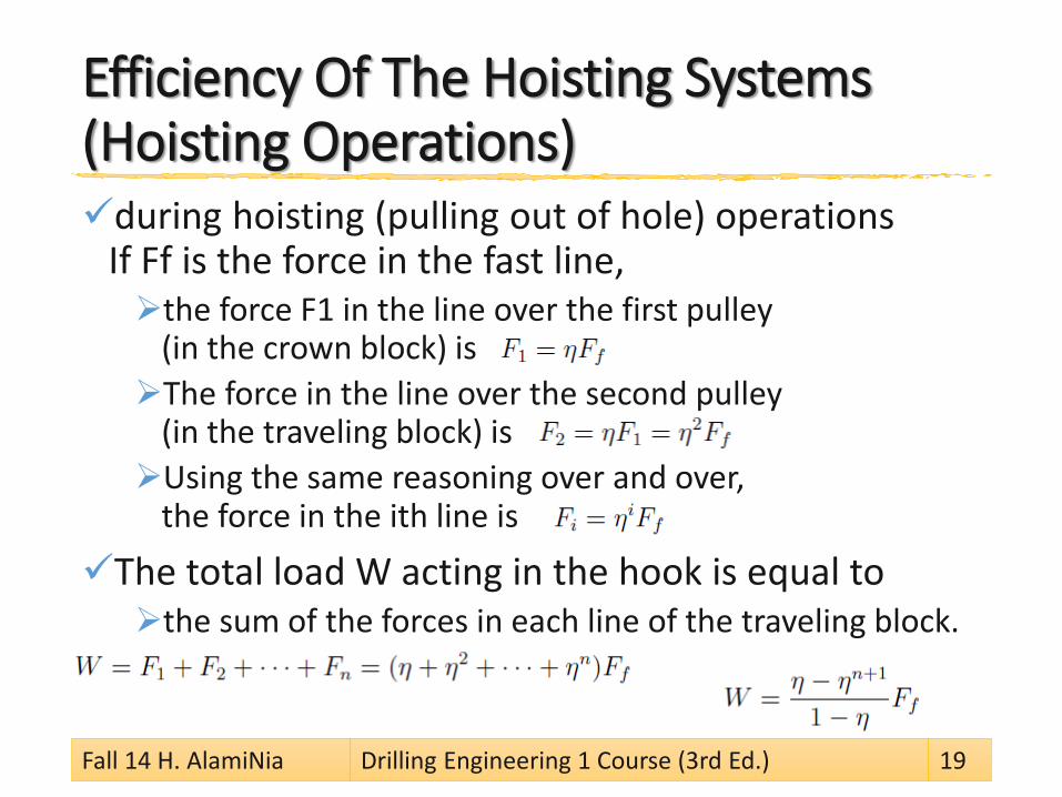
Efficiency Of The Hoisting Systems (Hoisting Operations)during hoisting (pulling out of hole) operations
If Ff is the force in the fast line, the force F1 in the line over the first pulley
(in the crown block) isThe force in the line over the second pulley
(in the traveling block) isUsing the same reasoning over and over,
the force in the ith line is
The total load W acting in the hook is equal to the sum of the forces in each line of the traveling block.
Fall 14 H. AlamiNia Drilling Engineering 1 Course (3rd Ed.) 19
Calculation of fast line load during hoisting
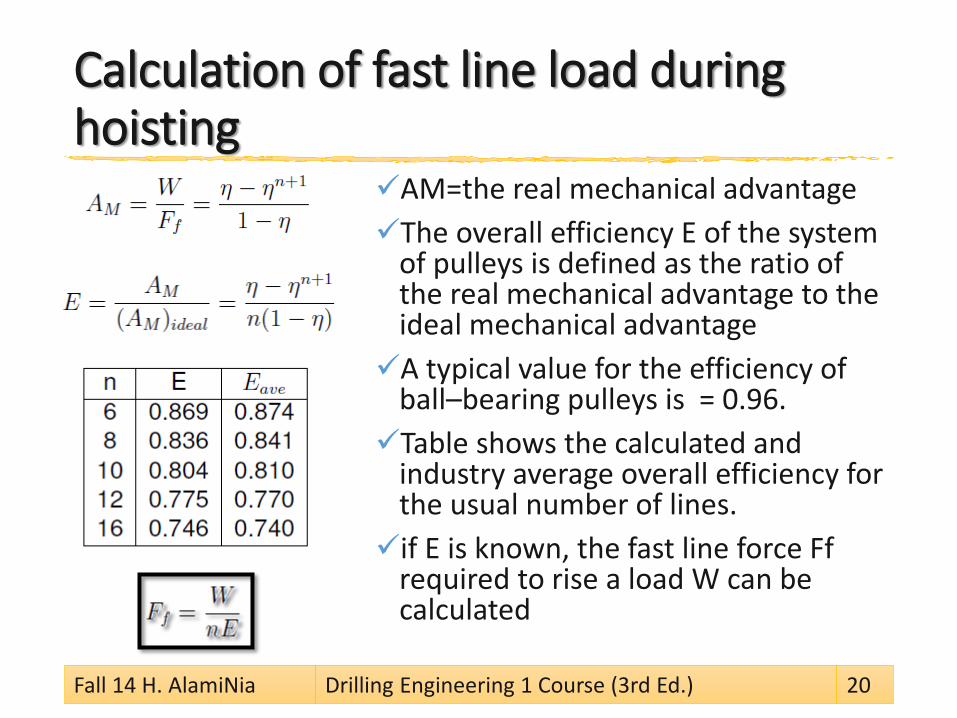
AM=the real mechanical advantageThe overall efficiency E of the system
of pulleys is defined as the ratio of the real mechanical advantage to the ideal mechanical advantageA typical value for the efficiency of
ball–bearing pulleys is = 0.96. Table shows the calculated and
industry average overall efficiency for the usual number of lines.if E is known, the fast line force Ff
required to rise a load W can be calculated
Fall 14 H. AlamiNia Drilling Engineering 1 Course (3rd Ed.) 20
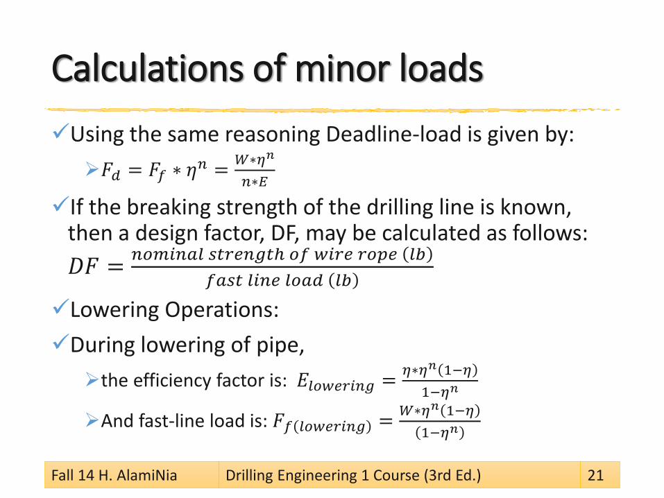
Calculations of minor loadsUsing the same reasoning Deadline-load is given by:𝐹𝐹𝑑𝑑 = 𝐹𝐹𝑓𝑓 ∗ 𝜂𝜂𝑛𝑛 = 𝑊𝑊∗𝜂𝜂𝑛𝑛
𝑛𝑛∗𝐸𝐸
If the breaking strength of the drilling line is known, then a design factor, DF, may be calculated as follows: 𝐷𝐷𝐹𝐹 = 𝑛𝑛𝑛𝑛𝑛𝑛𝑛𝑛𝑛𝑛𝑛𝑛𝑛𝑛 𝑠𝑠𝑠𝑠𝑠𝑠𝑠𝑠𝑛𝑛𝑠𝑠𝑠𝑠ℎ 𝑛𝑛𝑓𝑓 𝑤𝑤𝑛𝑛𝑠𝑠𝑠𝑠 𝑠𝑠𝑛𝑛𝑟𝑟𝑠𝑠 𝑛𝑛𝑙𝑙
𝑓𝑓𝑛𝑛𝑠𝑠𝑠𝑠 𝑛𝑛𝑛𝑛𝑛𝑛𝑠𝑠 𝑛𝑛𝑛𝑛𝑛𝑛𝑑𝑑 𝑛𝑛𝑙𝑙
Lowering Operations:During lowering of pipe, the efficiency factor is: 𝐸𝐸𝑛𝑛𝑛𝑛𝑤𝑤𝑠𝑠𝑠𝑠𝑛𝑛𝑛𝑛𝑠𝑠 = 𝜂𝜂∗𝜂𝜂𝑛𝑛 1−𝜂𝜂
1−𝜂𝜂𝑛𝑛
And fast-line load is: 𝐹𝐹𝑓𝑓 𝑛𝑛𝑛𝑛𝑤𝑤𝑠𝑠𝑠𝑠𝑛𝑛𝑛𝑛𝑠𝑠 = 𝑊𝑊∗𝜂𝜂𝑛𝑛 1−𝜂𝜂1−𝜂𝜂𝑛𝑛
Fall 14 H. AlamiNia Drilling Engineering 1 Course (3rd Ed.) 21


POWER REQUIREMENTS OF THE DRAWWORKSAs a rule of thumb,
the drawwork should have 1 HP for every 10 ft to be drilled. Hence for a 20,000 ft well,
the drawwork should have 2000 HP.
A more rigorous way of calculating the horse power requirements is to carry out output power at drum:𝑃𝑃d = Ff ∗ Vf = W
nE∗ n ∗ vb = W∗Vb
EIn the Imperial system, power is quoted in horse-power and the
above equation becomes:𝐷𝐷𝐷𝐷𝐷𝐷𝐷𝐷 𝑜𝑜𝐷𝐷𝑜𝑜𝑜𝑜𝐷𝐷𝑜𝑜 = W∗vbE∗33000
The proof has mentioned in the following slides:
Fall 14 H. AlamiNia Drilling Engineering 1 Course (3rd Ed.) 23
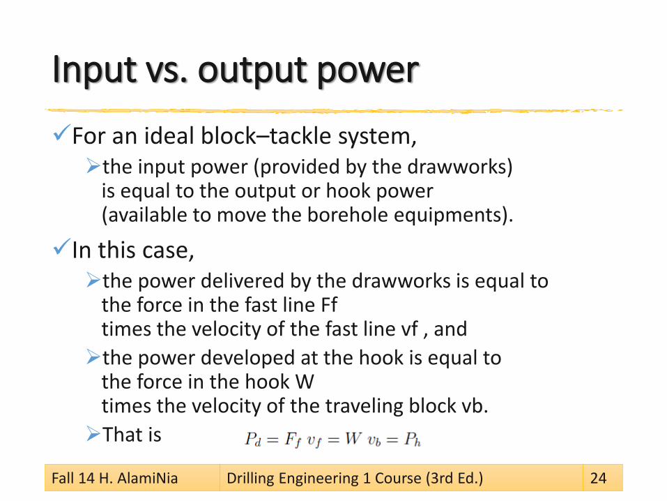
Input vs. output powerFor an ideal block–tackle system, the input power (provided by the drawworks)
is equal to the output or hook power (available to move the borehole equipments).
In this case, the power delivered by the drawworks is equal to
the force in the fast line Ff times the velocity of the fast line vf , and the power developed at the hook is equal to
the force in the hook W times the velocity of the traveling block vb. That is
Fall 14 H. AlamiNia Drilling Engineering 1 Course (3rd Ed.) 24
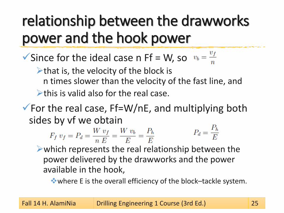
relationship between the drawworks power and the hook powerSince for the ideal case n Ff = W, sothat is, the velocity of the block is
n times slower than the velocity of the fast line, and this is valid also for the real case.
For the real case, Ff=W/nE, and multiplying both sides by vf we obtain
which represents the real relationship between the power delivered by the drawworks and the power available in the hook, where E is the overall efficiency of the block–tackle system.
Fall 14 H. AlamiNia Drilling Engineering 1 Course (3rd Ed.) 25

The Block & TackleA rig must hoist a load of 300,000 lbf.
The drawworks can provide a maximum input power to the block–tackle system of as 500 hp. Eight lines are strung between the crown block and traveling block. Calculate (1) the tension in the fast line
when upward motion is impending, (2) the maximum hook horsepower, (3) the maximum hoisting speed.
Fall 14 H. AlamiNia Drilling Engineering 1 Course (3rd Ed.) 26
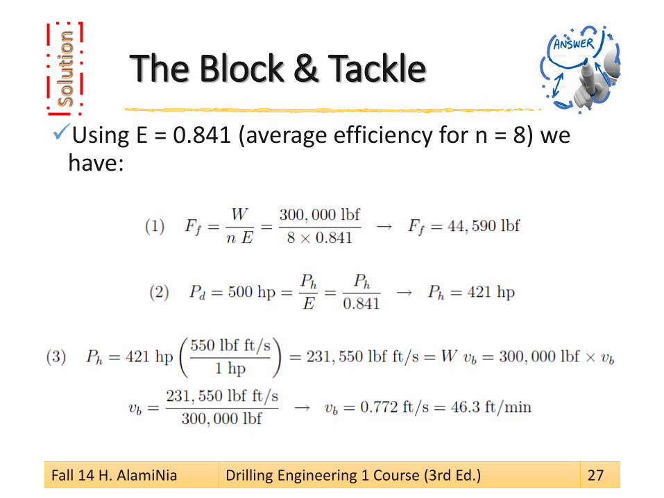
The Block & TackleUsing E = 0.841 (average efficiency for n = 8) we
have:
Fall 14 H. AlamiNia Drilling Engineering 1 Course (3rd Ed.) 27
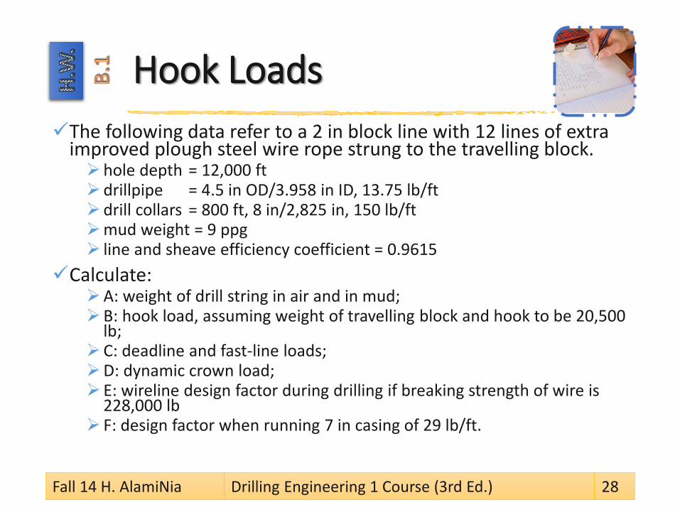
Hook LoadsThe following data refer to a 2 in block line with 12 lines of extra
improved plough steel wire rope strung to the travelling block.hole depth = 12,000 ftdrillpipe = 4.5 in OD/3.958 in ID, 13.75 lb/ft drill collars = 800 ft, 8 in/2,825 in, 150 lb/ft mud weight = 9 ppg line and sheave efficiency coefficient = 0.9615
Calculate:A: weight of drill string in air and in mud;B: hook load, assuming weight of travelling block and hook to be 20,500
lb;C: deadline and fast-line loads;D: dynamic crown load; E: wireline design factor during drilling if breaking strength of wire is
228,000 lb F: design factor when running 7 in casing of 29 lb/ft.
Fall 14 H. AlamiNia Drilling Engineering 1 Course (3rd Ed.) 28

Hook Loads
Clues: Example 16.2: Hook Loads, WEC PGO: 725
Weight of drillstring in air=weight of drillpipe + weight of drill collarsWeight of drillstring in mud
=buoyancy factor x weight in airHook load= weight of string in mud
+ weight of travelling block, etc.Dynamic crown load = Fd + Ff + W
Fall 14 H. AlamiNia Drilling Engineering 1 Course (3rd Ed.) 29

HOISTING DESIGN CONSIDERATIONS
The procedure for carrying out hoisting design calculations are as follows:Determine the deepest hole to be drilledDetermine the worst drilling loads or casing loadsUse these values to select
the drilling line, the derrick capacity and in turn the derrick
Fall 14 H. AlamiNia Drilling Engineering 1 Course (3rd Ed.) 31
The total load applied to the derrick
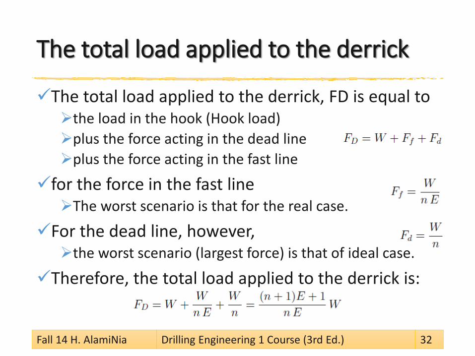
The total load applied to the derrick, FD is equal to the load in the hook (Hook load)plus the force acting in the dead line plus the force acting in the fast line
for the force in the fast line The worst scenario is that for the real case.
For the dead line, however, the worst scenario (largest force) is that of ideal case.
Therefore, the total load applied to the derrick is:
Fall 14 H. AlamiNia Drilling Engineering 1 Course (3rd Ed.) 32
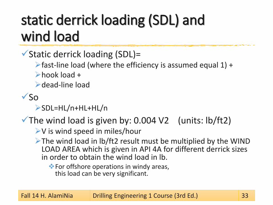
static derrick loading (SDL) and wind load Static derrick loading (SDL)= fast-line load (where the efficiency is assumed equal 1) + hook load + dead-line load
SoSDL=HL/n+HL+HL/n
The wind load is given by: 0.004 V2 (units: lb/ft2)V is wind speed in miles/hourThe wind load in lb/ft2 result must be multiplied by the WIND
LOAD AREA which is given in API 4A for different derrick sizes in order to obtain the wind load in lb. For offshore operations in windy areas,
this load can be very significant.
Fall 14 H. AlamiNia Drilling Engineering 1 Course (3rd Ed.) 33
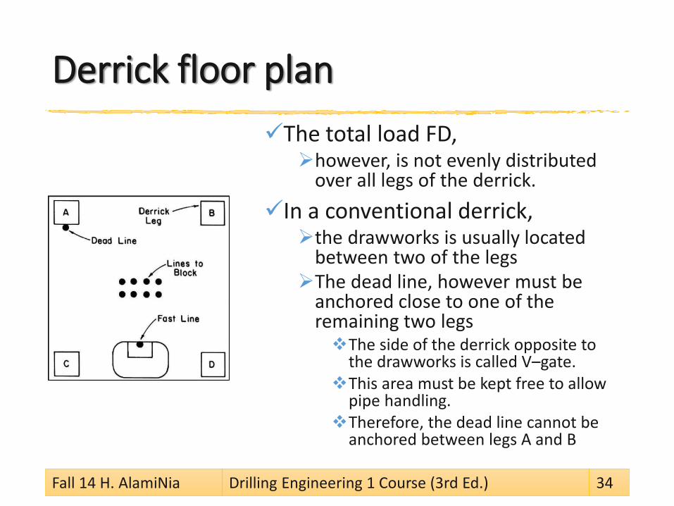
Derrick floor planThe total load FD,however, is not evenly distributed
over all legs of the derrick. In a conventional derrick,the drawworks is usually located
between two of the legsThe dead line, however must be
anchored close to one of the remaining two legsThe side of the derrick opposite to
the drawworks is called V–gate.This area must be kept free to allow
pipe handling. Therefore, the dead line cannot be
anchored between legs A and B
Fall 14 H. AlamiNia Drilling Engineering 1 Course (3rd Ed.) 34
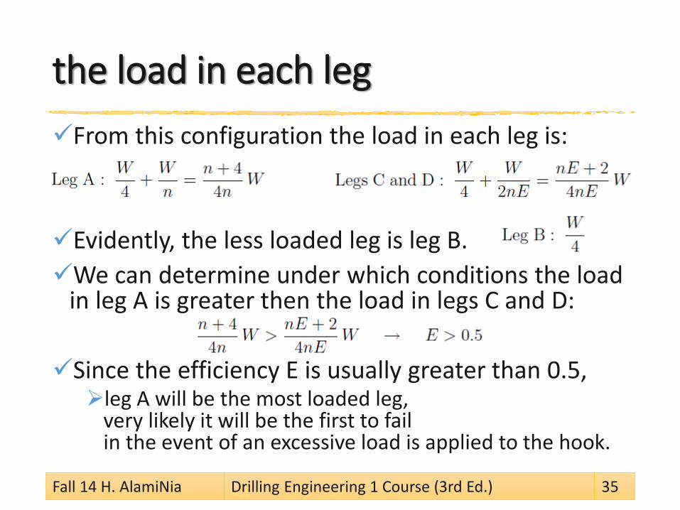
the load in each legFrom this configuration the load in each leg is:
Evidently, the less loaded leg is leg B. We can determine under which conditions the load
in leg A is greater then the load in legs C and D:
Since the efficiency E is usually greater than 0.5, leg A will be the most loaded leg,
very likely it will be the first to fail in the event of an excessive load is applied to the hook.
Fall 14 H. AlamiNia Drilling Engineering 1 Course (3rd Ed.) 35
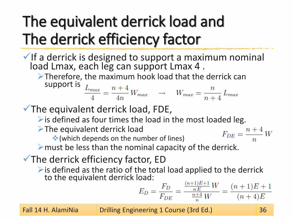
The equivalent derrick load andThe derrick efficiency factorIf a derrick is designed to support a maximum nominal
load Lmax, each leg can support Lmax 4 . Therefore, the maximum hook load that the derrick can
support is
The equivalent derrick load, FDE, is defined as four times the load in the most loaded leg. The equivalent derrick load
(which depends on the number of lines) must be less than the nominal capacity of the derrick.
The derrick efficiency factor, ED is defined as the ratio of the total load applied to the derrick
to the equivalent derrick load:
Fall 14 H. AlamiNia Drilling Engineering 1 Course (3rd Ed.) 36
derrick loadA rig must hoist a load of 300,000 lbf. Eight lines are strung between the crown block and
traveling block. calculate (1) the actual derrick load, (2) the equivalent derrick load, and (3) the derrick efficient factor.
Fall 14 H. AlamiNia Drilling Engineering 1 Course (3rd Ed.) 37
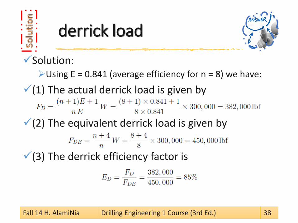
derrick loadSolution:Using E = 0.841 (average efficiency for n = 8) we have:
(1) The actual derrick load is given by
(2) The equivalent derrick load is given by
(3) The derrick efficiency factor is
Fall 14 H. AlamiNia Drilling Engineering 1 Course (3rd Ed.) 38
TON-MILES OF A DRILLING LINEThe drilling line, like any other drilling equipment, does
work at any time it is involved in moving equipment in or out of the hole. The amount of work done varies depending the
operation involved. This work causes the wireline to wear and if the line is not
replaced it will eventually break. The reader should note that the drilling line can only contact a
maximum of 50% of the sheaves at any one time, but the damage will be done on the contact area any way.
The amount of work done need to be calculated to determine when to change the drilling line.
Fall 14 H. AlamiNia Drilling Engineering 1 Course (3rd Ed.) 39
Evaluation Of Total Service And Cut-off PracticePortions of the drilling line on the crown and
travelling blocks sheaves and on the hoisting drum carry the greatest amount of work and are subjected to a great deal of wear and tear. These parts must be cut and removed at regular times
other wise the drilling line will fail by fatigue. The process is called "slip and cut practice".
The length of line to be cut is equal to Length of drum laps =
number of laps x drum circumference
Fall 14 H. AlamiNia Drilling Engineering 1 Course (3rd Ed.) 40
1. (CDF) Jorge H.B. Sampaio Jr. “Drilling Engineering Fundamentals.” Master of Petroleum Engineering. Curtin University of Technology, 2007. Chapter 2
2. (WEC) Rabia, Hussain. Well Engineering & Construction. Entrac Consulting Limited, 2002.Chapter 16