hollister-whitney elevator corporation · thank you for choosing a hollister-whitney, ac, permanent...
TRANSCRIPT

Hollister-Whitney Elevator Corporation #1 Hollister-Whitney Parkway Fax: 217-222-0493
Quincy, IL 62305 e-mail: [email protected]
Phone: 217-222-0466 www.hollisterwhitney.com
Bulletin 1162
Page 1 of 32
PUR #674 REV. C - LTL
Hollister-Whitney Elevator Corporation
Installation and Service Manual
GL101, GL131, GL171, GL130A, GL185 and GL260
AC Permanent Magnet, Gearless Machines

Hollister-Whitney Elevator Corporation #1 Hollister-Whitney Parkway Fax: 217-222-0493
Quincy, IL 62305 e-mail: [email protected]
Phone: 217-222-0466 www.hollisterwhitney.com
Bulletin 1162
Page 2 of 32
PUR #674 REV. C - LTL
Table of Contents I. Introduction
II. Machine Specifications
a. Duty Tables
b. Maximum System Loads
c. Brake Specifications
d. Machine Properties, Dimensions and Parts Lists
III. Receipt, Handling, Storage and Commissioning
a. Receipt
b. Handling
c. Disassembly / Reassembly
d. Storage
i. Short-Term Storage
ii. Long-Term Storage
e. Commissioning
IV. Installation
a. Machine Mounting
i. Traditional Overhead and Machine-Room-Less Mounting
ii. Traditional Basement Set Mounting
b. Electrical Connections
i. Machine Wiring
ii. Encoder Wiring
c. Startup
d. Brake Burnishing
e. Manual Brake Release (Optional Equipment)
V. Basic Service
• Maintenance
• Mayr #6 & #8 Brakes
a. Brake Air Gap Check Procedure
b. Brake Adjustment
i. Side-to-Side Adjustments
ii. Top-to-Bottom Adjustments
c. Manual Brake Release Adjustments (if so equipped)
d. Brake Wear – Check Procedure
• Mayr #10 Brakes
a. Brake Air Gap Check Procedure
b. Brake Adjustment
i. Side-to-Side Adjustments
ii. Top-to-Bottom Adjustments
iii. Guide Bolt Alignment
c. Manual Brake Release Adjustments (if so equipped)
d. Brake Wear – Check Procedure
VI. Warranty and Repair Information
VII. Support Documentation
• GL Metric Duty and Max. System Loads Tables
• GL Machine – Selection of Optional Configuration Images
• GL Machine Prints
• Encoder Information
• KEB Encoder Cable

Hollister-Whitney Elevator Corporation #1 Hollister-Whitney Parkway Fax: 217-222-0493
Quincy, IL 62305 e-mail: [email protected]
Phone: 217-222-0466 www.hollisterwhitney.com
Bulletin 1162
Page 3 of 32
PUR #674 REV. C - LTL
I. Introduction
Thank you for choosing a Hollister-Whitney, AC, Permanent Magnet, Gearless Machine!
The GL101, GL131, GL171, GL130A, GLl85 and GL260 machines have all been designed for use in
machine room applications with VVVF controls. Machines are also designed with 28 or 40 poles to provide
smoother, quieter, cooler and longer lasting operation.
"L" models are designed to run at lower voltages, but will require higher current supplies. Example: A
GL171-20L, with 20” wheel, 2000# capacity, 200 fpm, requires 170V (208V supply) at 32 amps with 40% counter
balance weight. Some machines run at speeds up to twice as fast as those listed in Tables 1 & 2 when supplied with
440 volts, all while maintaining the same current. For higher speed machines consult Hollister-Whitney
Engineering. (The maximum BTU/Hour output of the machine will be double the value shown in Tables 1, 2 & 3.)
"H" models are designed to run at lower currents, but will require higher voltage supplies. Example: A
GL171-20H, with 20” wheel, 2000# capacity, 200 fpm, requires 360V (440V supply) at 16 amps with 40% counter
balance weight. These machines can also run at speeds down to half as fast as those listed in Tables 1 & 2 when
supplied with 230 volts, all while maintaining the same current. (The maximum BTU/Hour output of the machine
will be half the value shown in Tables 1, 2 & 3.)
Hollister-Whitney machines are designed to perform in a tolerant machine space. The machine space
working temperature should be held between 50°F & 100°F, (10°C & 37.8°C) and humidity should be held to an
average of 90% non-condensing.
II. Machine Specifications
Each Hollister-Whitney, GL series machine includes the following standard equipment:
• Sealed, maintenance-free bearings.
• De-mountable traction sheave with 105° Undercut "U" grooves standard, with other groove profiles
available on request
• Main disc brakes, capable of holding 125% of the load. (Emergency brake available)
• Brake switches (wired normally open - standard.)
• En-dat Encoder & Cable (15 to 75 meter cable lengths available standard)
• Finishing Base Frame
Hollister-Whitney Elevator Corporation #1 Hollister-Whitney Parkway Fax: 217-222-0493
Quincy, IL 62305 e-mail: [email protected]
Phone: 217-222-0466 www.hollisterwhitney.com
Bulletin 1162
Page 4 of 32
PUR #674 REV. C - LTL
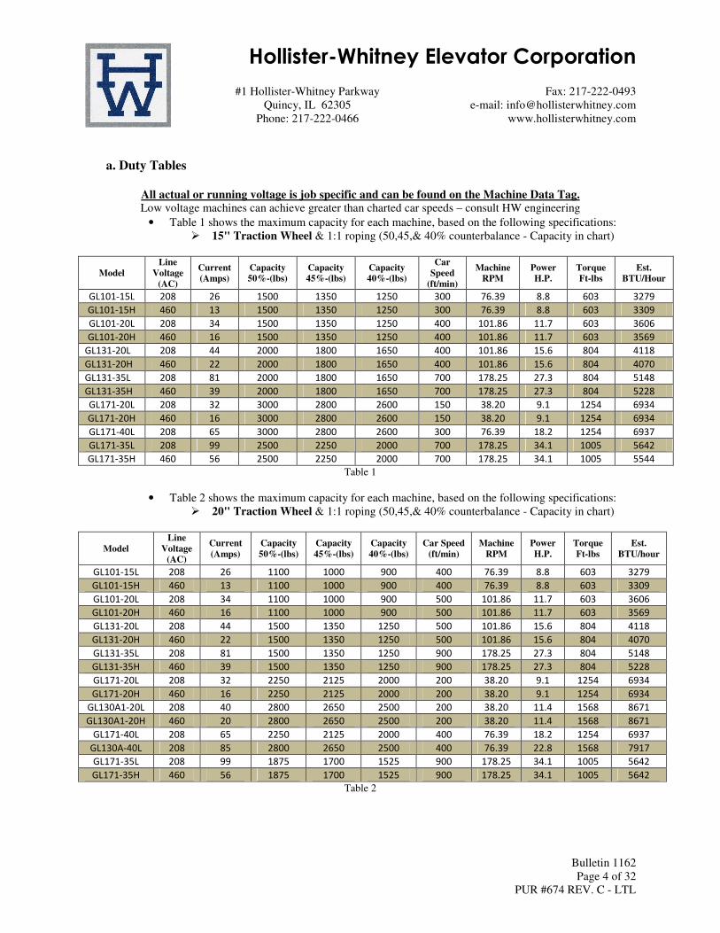
a. Duty Tables
All actual or running voltage is job specific and can be found on the Machine Data Tag.
Low voltage machines can achieve greater than charted car speeds – consult HW engineering
• Table 1 shows the maximum capacity for each machine, based on the following specifications:
� 15" Traction Wheel & 1:1 roping (50,45,& 40% counterbalance - Capacity in chart)
Model
Line
Voltage
(AC)
Current
(Amps)
Capacity
50%-(lbs)
Capacity
45%-(lbs)
Capacity
40%-(lbs)
Car
Speed
(ft/min)
Machine
RPM
Power
H.P.
Torque
Ft-lbs
Est.
BTU/Hour
GL101-15L 208 26 1500 1350 1250 300 76.39 8.8 603 3279
GL101-15H 460 13 1500 1350 1250 300 76.39 8.8 603 3309
GL101-20L 208 34 1500 1350 1250 400 101.86 11.7 603 3606
GL101-20H 460 16 1500 1350 1250 400 101.86 11.7 603 3569
GL131-20L 208 44 2000 1800 1650 400 101.86 15.6 804 4118
GL131-20H 460 22 2000 1800 1650 400 101.86 15.6 804 4070
GL131-35L 208 81 2000 1800 1650 700 178.25 27.3 804 5148
GL131-35H 460 39 2000 1800 1650 700 178.25 27.3 804 5228
GL171-20L 208 32 3000 2800 2600 150 38.20 9.1 1254 6934
GL171-20H 460 16 3000 2800 2600 150 38.20 9.1 1254 6934
GL171-40L 208 65 3000 2800 2600 300 76.39 18.2 1254 6937
GL171-35L 208 99 2500 2250 2000 700 178.25 34.1 1005 5642
GL171-35H 460 56 2500 2250 2000 700 178.25 34.1 1005 5544
Table 1
• Table 2 shows the maximum capacity for each machine, based on the following specifications:
� 20" Traction Wheel & 1:1 roping (50,45,& 40% counterbalance - Capacity in chart)
Model
Line
Voltage
(AC)
Current
(Amps)
Capacity
50%-(lbs)
Capacity
45%-(lbs)
Capacity
40%-(lbs)
Car Speed
(ft/min)
Machine
RPM
Power
H.P.
Torque
Ft-lbs
Est.
BTU/hour
GL101-15L 208 26 1100 1000 900 400 76.39 8.8 603 3279
GL101-15H 460 13 1100 1000 900 400 76.39 8.8 603 3309
GL101-20L 208 34 1100 1000 900 500 101.86 11.7 603 3606
GL101-20H 460 16 1100 1000 900 500 101.86 11.7 603 3569
GL131-20L 208 44 1500 1350 1250 500 101.86 15.6 804 4118
GL131-20H 460 22 1500 1350 1250 500 101.86 15.6 804 4070
GL131-35L 208 81 1500 1350 1250 900 178.25 27.3 804 5148
GL131-35H 460 39 1500 1350 1250 900 178.25 27.3 804 5228
GL171-20L 208 32 2250 2125 2000 200 38.20 9.1 1254 6934
GL171-20H 460 16 2250 2125 2000 200 38.20 9.1 1254 6934
GL130A1-20L 208 40 2800 2650 2500 200 38.20 11.4 1568 8671
GL130A1-20H 460 20 2800 2650 2500 200 38.20 11.4 1568 8671
GL171-40L 208 65 2250 2125 2000 400 76.39 18.2 1254 6937
GL130A-40L 208 85 2800 2650 2500 400 76.39 22.8 1568 7917
GL171-35L 208 99 1875 1700 1525 900 178.25 34.1 1005 5642
GL171-35H 460 56 1875 1700 1525 900 178.25 34.1 1005 5642
Table 2

Hollister-Whitney Elevator Corporation #1 Hollister-Whitney Parkway Fax: 217-222-0493
Quincy, IL 62305 e-mail: [email protected]
Phone: 217-222-0466 www.hollisterwhitney.com
Bulletin 1162
Page 5 of 32
PUR #674 REV. C - LTL
• Table 3 shows the maximum capacity for each machine, based on the following specifications:
� 25" Traction Wheel & 1:1 roping (50,45,& 40% counterbalance - Capacity in chart)
Model
Line
Voltage
(AC)
Current
(Amps)
Capacity
50%-(lbs)
Capacity
45%-(lbs)
Capacity
40%-(lbs)
Car Speed
(ft/min)
Machine
RPM
Power
H.P.
Torque
Ft-lbs
Est.
BTU/hour
GL130A-20L 208 40 2250 2125 2000 250 38.20 11.4 1568 8671
GL130A-20H 460 20 2250 2125 2000 250 38.20 11.4 1568 8671
GL185-35L 208 78 3400 3150 3000 350 53.48 24.0 2357 6789
GL185-35H 460 38 3400 3150 3000 350 53.48 24.0 2357 6789
GL260-35L 208 115 4500 4250 4000 350 53.48 32.0 3138 9038
GL260-35H 460 55 4500 4250 4000 350 53.48 32.0 3138 9038
GL130A-40L 208 85 2250 2125 2000 500 76.39 22.8 1568 7917
GL185-50L 208 105 3400 3150 3000 500 76.39 34.3 2357 9698
GL185-50H 460 50 3400 3150 3000 500 76.39 34.3 2357 9698
GL260-50L 208 150 4500 4250 4000 500 76.39 45.7 3138 12911
GL260-50H 460 76 4500 4250 4000 500 76.39 45.7 3138 12911
GL185-70L 208 148 3400 3150 3000 700 106.95 48.0 2357 13577
GL260-70L 208 225 4500 4250 4000 700 106.95 63.9 3138 18076
Table 3
b. Maximum System Loads
• The maximum system loads shown in Table 4 are based on 50% counterbalance and 1:1 roping.
• The overall system load is calculated by adding together the following items:
� Total empty car weight + Total counterweight + Capacity + Total hoist rope weight +
Total compensation weight + Total traveling cable weight
� Consult HW engineering for specific Machine/Speed/Capacity combinations in
highlighted boxes
� Some Speed & Capacity combinations not yet available
Shaded boxes Represent different Sizes of Motor Windings per Machine Size
Car Speed
(fpm)
15” T.W. 20” T.W. 25” T.W.
GL101 GL131 GL171 GL101 GL131 GL171 GL130A GL130A GL185 GL260
50 23000 24800 25700 23000 24800 25700 24750 24750 23900 26700
100 23000 24800 25700 23000 24800 25700 24750 24750 23900 26700
150 23000 24800 25700 23000 24800 25700 24750 24750 23900 26700
200 23000 24800 25700 23000 24800 25700 24750 24750 23900 26700
250 23000 24800 25700 23000 24800 25700 24750 24750 23900 26700
300 23000 24800 25700 23000 24800 25700 24750 24750 23900 26700
350 23000 24800 25700 23000 24800 25700 24750 24750 23900 26700
400 23000 24800 25700 23000 24800 25700 24750 24750 23700 26700
450 22350 24800 25700 23000 24800 25700 24750 24750 22900 26700
500 21650 24800 25600 23000 24800 25700 24750 24750 22200 26700
550 21000 24800 24900 22900 24800 25700 24750 24750 21500 26700
600 20500 24250 24200 22300 24800 25700 24750 24750 21000 26700
650 20000 23650 23600 21800 24800 25700 24750 24750 20500 26700
700 19550 23150 23100 21300 24800 25200 24750 24750 20000 26700
Table 4

Hollister-Whitney Elevator Corporation #1 Hollister-Whitney Parkway Fax: 217-222-0493
Quincy, IL 62305 e-mail: [email protected]
Phone: 217-222-0466 www.hollisterwhitney.com
Bulletin 1162
Page 6 of 32
PUR #674 REV. C - LTL
c. Brake Specifications
• 115 VDC model brake is supplied standard from the factory. Refer to Table 5.
• Brake Switch: Rating 250 VAC, 3A; Recommended Switching Current 24VDC, 10 to 50 mA;
(Minimum 12VDC, 10mA)
• Switches can be wired: Normal Open, - Black & Blue wires - as shipped
Normal Closed - Black & Gray wires
Brake Model: Mayr 6
GL101 & GL171
Mayr 8
GL131
Mayr 10
GL130A, GL185, &
GL260
Pick Voltage (VDC): [email protected] [email protected] [email protected]
Pick Power (W): 155 236 375
Hold Voltage (VDC): [email protected] [email protected] [email protected]
Hold Power (W): 39 59 94
Resistance (ohms) 69.8 45.8 28.8
Table 5
• The machine brakes may be mounted in up to 5 locations around the body of the machine to
provide flexibility in machine placement and proximity to other equipment or walls. Refer to
Figure 1 for the standard and optional brake mounting locations.
Figure 1 (4 brakes shown as representation only)
Standard
Mounting
Location #1
Standard
Mounting
Location #2
Optional
Mounting
Location #1
Optional
Mounting
Location #2
Optional
Mounting
Location #3

Hollister-Whitney Elevator Corporation #1 Hollister-Whitney Parkway Fax: 217-222-0493
Quincy, IL 62305 e-mail: [email protected]
Phone: 217-222-0466 www.hollisterwhitney.com
Bulletin 1162
Page 7 of 32
PUR #674 REV. C - LTL
• Top mount - Optional mounting location #3 – Only available on some machines – Consult
Hollister-Whitney Engineering.
• If brakes are to be mounted using either of the optional mounting locations shown in Figure 1,
mounting positions should be requested at the time of ordering. Brakes may be relocated in the
field when necessary. Contact Hollister-Whitney for instructions.
d. Machine Properties, Dimensions and Parts Lists
• See attachments in Section VIII “Support Documentation” at back of manual for machine
dimensions and parts lists:
� GL101 Dimensions & Parts List
� GL131 Dimensions & Parts List
� GL171 Dimensions & Parts List
� GL130A Dimensions & Parts List
� GL185 Dimensions & Parts List
� GL260 Dimensions & Parts List
III. Receipt, Handling, Storage and Commissioning
a. Receipt
• Upon delivery of the machine, inspect the machine for damage. If any damage due to
transportation is noted, contact the carrier and Hollister-Whitney.
• Check the machine data tag to ensure the machine conforms to your order. (An example data tag
is shown in Figure 2.)
Figure 2
b. Handling
• The machine will be delivered on wooden boards. The machine may be left on boards and moved
with standard fork truck or pallet jack equipment.

Hollister-Whitney Elevator Corporation #1 Hollister-Whitney Parkway Fax: 217-222-0493
Quincy, IL 62305 e-mail: [email protected]
Phone: 217-222-0466 www.hollisterwhitney.com
Bulletin 1162
Page 8 of 32
PUR #674 REV. C - LTL
• When the machine is removed from boards, it must be moved by hoisting through holes provided
in machine base. Figure 3
• When hoisting the machine, mount and use hoisting rigging so that it does not rest against the
machine. This will reduce the damage that might be cause during movement and installation.
• Use Table 6 to determine your specific machine weight. Weights are approx., since other options
might be added by customer, (extra brakes, rope gripper, etc.)
Machine Weight
Model Weight Weight
GL101 2000 lbs. 910 kg
GL131 2300 lbs. 1040 kg
GL171 2400 lbs. 1100 kg
GL130A 3900 lbs. 1770 kg
GL185 4300 lbs. 1950 kg
GL260 4800 lbs. 2200 kg
Table 6
Figure 3
DO NOT USE ANY OTHER MACHINE COMPONENT TO LIFT THE MACHINE! USE
ONLY THE MACHINE BASE WHEN LIFTING AND MOVING THE MACHINE!
HOISTING THE MACHINE BY ANY OTHER COMPONENT WILL RESULT IN DAMAGE
TO THE MACHINE AND POSSIBLE FAILURE RESULTING IN THE MACHINE
FALLING FROM THE HOISTING SYSTEM!
• Follow all the necessary safety precautions to avoid damage to the machine or risk to personnel
when moving the machine.

Hollister-Whitney Elevator Corporation #1 Hollister-Whitney Parkway Fax: 217-222-0493
Quincy, IL 62305 e-mail: [email protected]
Phone: 217-222-0466 www.hollisterwhitney.com
Bulletin 1162
Page 9 of 32
PUR #674 REV. C - LTL
c. Disassembly / Reassembly (Disassembly of Machine is not recommended!)
Disassembly of Machine VOIDS Warranty
If disassembly must be done to get machine to final position please follow procedure below
• Step 1: Remove End Caps
� Use a hex wrench, loosen and remove (6) Outboard Stand End Cap bolts. (See Figure 4)
Remove End Cap, slide Bearing End Cap against Traction Sheave
• Step 2: Remove Outboard Stand
� Mark front side of Outboard Stand. Loosen and remove Outboard Stand mounting
bolts.(See Figure 5)
Figure 4 Figure 5
� Slide Outboard Stand off Base Fabrication. Do not force or put Outboard Stand in a bind,
as this will cause damage to the Outboard Stand Bearing. NOTE: if shims are present
under Outboard Stand, note their location and quantity. These shims will have to be placed
in same location, to correctly align Outboards Stand to Motor upon reassembly.
• Step 3: Remove Motor from Base Fabrication
� Loosen and remove bolts holding Motor Housing to Base Fabrication.
� Remove plugs from top of Motor Housing, insert Hoisting Eye Bolts, lift Motor using eye
bolts and pull straight up with spreader, or other rigging apparatus. (See Figure 6) Use eye
bolts to lift only motor, not complete machine assembly � If shims are present, note there location and quantity.

Hollister-Whitney Elevator Corporation #1 Hollister-Whitney Parkway Fax: 217-222-0493
Quincy, IL 62305 e-mail: [email protected]
Phone: 217-222-0466 www.hollisterwhitney.com
Bulletin 1162
Page 10 of 32
PUR #673 REV. B - LTL
Figure 6 – GL171 with 2 lifting eye bolts installed
Figure 7
• Step 4: Install Machine
� Follow guidelines below in section IV. Installation
• Step 5: Reassemble Machine on Base Fabrication
� Hoist Motor onto Base Fabrication. Remember to install shims where they were located in
Step 3. Tighten bolts through Fabricated Base.
� Hoist Outboard Stand onto Base Fabrication. Remember to install shims where they were
located in Step 2. When installing Outboard Stand use extreme care when sliding Stand
over Bearing so that you don’t bind the Outboard Stand Bearing in any way.
• Step 6: Check alignment of Outboard Stand to Motor
� Use a Dial Indicator mounted on a Magnetic Base. Set Magnetic Base on Motor Shaft and
rest Indicator against Outboard Stand Bolting rim. Check Outboard Stand is in Alignment
with Motor by turning motor by hand. Adjust Outboard stand as necessary and double
check final alignment prior to removing indicator. (See Figure 7)
� Tighten Outboard Stand Bolts.
• Step 7: Install Caps:
� Slide Bearing End Cap against back of Outboard Stand. Install Front Bearing End Cap on
Front of Outboard Stand. Bolt 2 End Caps together.

Hollister-Whitney Elevator Corporation #1 Hollister-Whitney Parkway Fax: 217-222-0493
Quincy, IL 62305 e-mail: [email protected]
Phone: 217-222-0466 www.hollisterwhitney.com
Bulletin 1162
Page 11 of 32
PUR #674 REV. C - LTL
d. Storage
i. Short-Term Storage
• For short-term storage, place the machine in a warm, dry and clean environment.
• Protect the machine from harsh weather conditions and temperature variations that can
lead to condensation.
• Protect the machine from dust, dirt and metal shavings. Metal dust and shavings can be
attracted into the machine by the magnets.
ii. Long-Term Storage
• For long-term storage, place the machine in a sealed, waterproof enclosure with a
dehydrating packet that is sized for the enclosure volume and humidity level.
• Follow the same instructions as outlined in Section III.d.i - "Short-term storage."
e. Commissioning
• Before the machine is installed, and before any voltage is applied, check the machine for
condensation or any evidence of condensation or water. If any evidence of wetness is found,
contact Hollister-Whitney for drying instructions.
• If wetness has been found and the machine has been dried, it will be necessary to re-verify the
insulation between each coil phase and earth ground.
� Using an insulation tester (or megohm-meter), check the insulation resistance at 500
VDC. The resistance should be NO LESS than 100 Mohm.
• If the machine has gotten wet during transportation, contact the carrier and Hollister-Whitney.
IV. Installation
a. Machine Mounting
• Before hoisting the machine into place, verify all the hoisting equipment is rated for the weight of
the machine. Refer to Table 6.
• Refer to Section III.b - "Handling" for the proper hoisting and handling procedures.
• Provide a level, structural support rated for the load on the machine.
• Ensure there is proper clearance around the machine for maintenance and adjustments.
• The machine may be mounted in traditional overhead and machine-room-less applications with
down-pull on the traction sheave, or in basement set application with up-pull on the traction
sheave. Special Machine Base fabrications are available for basement set applications.
i. Traditional Overhead
• Anchor the machine base to the structural support using the mounting hole locations in
the base.
• The bolts and washers required to anchor the machine base to the support, when not
provided, should be Grade 5 minimum (Bolts adhering to ASTM A325 are also suitable),
and of sufficient size and quantity to secure the machine from movement, with
consideration for adherence to all applicable building codes and ASME A17.1.

Hollister-Whitney Elevator Corporation #1 Hollister-Whitney Parkway Fax: 217-222-0493
Quincy, IL 62305 e-mail: [email protected]
Phone: 217-222-0466 www.hollisterwhitney.com
Bulletin 1162
Page 12 of 32
PUR #674 REV. C - LTL
• Hollister-Whitney does not typically include the machine mounting hardware with the
machine due to variations in structural machine support.
ii. Basement Set Mounting
• Basement Set Machines are available, machine base fabrications and mounting plates
specially designed for up-pull applications.
• Mounting plates are available for New Pour applications, and for adapting to Existing
Structures.
• Refer to all applicable building codes and ASME A17.1 when selecting hardware (or
other anchoring systems) to anchor the machine mounting plates to the structural supports
in an up-pull application.
• Use the more stringent criteria between the building codes, ASME A17.1 and the
minimum bolt grades identified in Section IV.a.i.
b. Electrical Connections
i. Machine Wiring
BEFORE PERFORMING ANY ELECTRICAL CONNECTIONS, MAKE SURE THAT POWER
SUPPLY IS TURNED OFF. ONLY THEN PROCEED WITH CONNECTING ELECTRICAL LEEDS
TO POWER SUPPLY. NEVER WORK IN MACHINES ELECTRICAL ENCLOSURE WHILE POWER
SUPPLY IS ON!!!
• Thermal Protection Switch (TPS) is wired with leads labeled and supplied into the machine
electrical enclosure. Refer to Figure 8. Contacts are Normally Closed, opening if an overheat
condition exists, and will close again after the machine has cooled to safe operating
temperatures.
• Consult your controller manufacturer for appropriate TPS connections.
• Verify the electrical supply from the elevator drive and brake power supplies match the
machine data tag. Refer to Figures 2.
• Connect the U-V-W lines from the drive as they correspond to motor. See Figure 8.
• Earth Ground connects to the ground lug terminal inside the electrical enclosure.
• Connect the machine and emergency brakes where shown in Figure 8.
• The brake switches are wired Normally Open from Hollister-Whitney. To change the switches
to function as normally closed, remove the blue wire from the terminal block in the electrical
enclosure, and replace it with the spare gray wire coming from the brake switch.
• NOTE – The GL171 machine brakes are to be wired together to function as a single machine
brake with the rope gripper (or second set of brakes) acting as the emergency brake.
• Kits are available for field relocation of the electrical enclosure. The electrical enclosure
location can also be relocated at the factory at the time of machine assembly.
THE MACHINE AND EMERGENCY BRAKE COILS MUST BE INDEPENDENT!
IT IS THE RESPONSIBILITY OF THE USER TO CONNECT THE MOTOR IN ACCORDANCE
WITH THE CURRENT LEGISLATION AND REGULATIONS IN THE COUNTRY OF USE. THIS
IS PARTICULARLY IMPORTANT IN REGARDS TO WIRE SIZES USED TO CONNECT THE
POWER AND EARTH GROUND AND THE TYPE AND SIZE OF FUSES.

Hollister-Whitney Elevator Corporation #1 Hollister-Whitney Parkway Fax: 217-222-0493
Quincy, IL 62305 e-mail: [email protected]
Phone: 217-222-0466 www.hollisterwhitney.com
Bulletin 1162
Page 13 of 32
PUR #674 REV. C - LTL
Relocation of electrical box is an available option: Factory Installed Shown, Field Kit Available.
Can be located at any open (see Figure 1) Brake Mounting position.
Figure 8
ii. Encoder wiring
• Connect the supplied encoder cable to the encoder on the back of the machine.
• When using a KEB drive, the encoder cable can be used "as-is."
• When using any other manufacturer's drive, consult control manufacturer for cable
compatibility and availability. DO NOT modify the KEB cable without first consulting
the control manufacturer. Any modification of the KEB cable voids the warranty.
• There are 2 cable classifications and each has its own color coding per cable. See
attachments in Section VIII “Support Documentation” at end of manual for diagrams.
� 30m and under – 00.F5.0C1-4005 document
� 40m and over – 00.F5.0C1-L005 document
Connect Earth Ground Here Connect Machine
Brake Coil Here
Connect Machine
Brake Switch Here
Connect Emergency
Brake Switch Here
Connect Emergency
Brake Coil Here W
V
U
THERMAL
PROTECTION
SWITCH WIRES
Attach Controller Wires this side

Hollister-Whitney Elevator Corporation #1 Hollister-Whitney Parkway Fax: 217-222-0493
Quincy, IL 62305 e-mail: [email protected]
Phone: 217-222-0466 www.hollisterwhitney.com
Bulletin 1162
Page 14 of 32
PUR #674 REV. C - LTL
c. Startup
• Verify all the motor related settings in the elevator controller match the information on the
machine data tag. Refer to Figures 2.
• Verify that all the brake parameters match the information on the machine data tag. Refer to
Figures 2.
• Remove any dirt, grease or rust that may have accumulated on the brake rotor during storage or
installation. Use fine sandpaper or emery cloth with light pressure to remove rust from the rotor,
taking care to keep the rust and metal dust out of the machine.
• Follow the controller manufacturer's procedure for alignment of the magnets.
• Briefly run the machine to verify the machine functionality and brake operation.
• Verify the drive sheave is plumb and aligned with the rope drop locations.
• Install the hoist ropes, adjust the rope shackles and check the ropes for equal tension. The rope
tension must be uniform or it may cause vibration and premature wear on the traction sheave and
hoist ropes.
• Re-verify the traction sheave is plumb once the machine is fully loaded.
d. Brake Burnishing
BRAKES MUST BE BURNISHED TO ACHIEVE
FULL STOPPING TORQUE!
• Each brake on the machine must be burnished separately. Repeat the following procedure for each
brake.
• Clamp the brake on the rotor. (De-energize the brake circuit.)
• Run the elevator in the direction of the load at 11 RPM for 1 minute
• If the overall travel of the elevator will not allow the burnishing time listed to be met on one pass,
open (energize) the brake at the bottom of the hoist way, lift the load back to the top and repeat the
run until the full burnishing time has been achieved.
• Stop occasionally to ensure the rotor and brake do not overheat.
• After burnishing, re-verify the air gap between the brake pads and the rotor. For brake check
procedure and service follow Sections V.a. thru V.c. or VI.a. thru VI.c.
• Air gap should remain at approx. 0.020 inch
*** NOTE: Air gap can surpass 0.020 inch, but must not exceed 0.040 inch. ***
Hollister-Whitney Elevator Corporation #1 Hollister-Whitney Parkway Fax: 217-222-0493
Quincy, IL 62305 e-mail: [email protected]
Phone: 217-222-0466 www.hollisterwhitney.com
Bulletin 1162
Page 15 of 32
PUR #674 REV. C - LTL
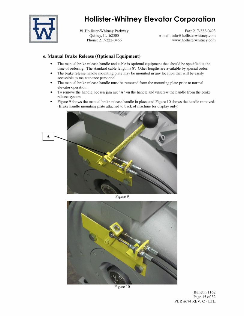
e. Manual Brake Release (Optional Equipment)
• The manual brake release handle and cable is optional equipment that should be specified at the
time of ordering. The standard cable length is 8'. Other lengths are available by special order.
• The brake release handle mounting plate may be mounted in any location that will be easily
accessible to maintenance personnel.
• The manual brake release handle must be removed from the mounting plate prior to normal
elevator operation.
• To remove the handle, loosen jam nut "A" on the handle and unscrew the handle from the brake
release system.
• Figure 9 shows the manual brake release handle in place and Figure 10 shows the handle removed.
(Brake handle mounting plate attached to back of machine for display only)
Figure 9
Figure 10
A