hoogwerk s65
DESCRIPTION
HoogwerkerTRANSCRIPT
ServiceManual
TechnicalPublications
First Edition, First PrintingPart No. 34476
S-60®
S-65®
Genie S-60 & Genie S-65 Part No. 34476
Service Manual - First Edition
ii
Introduction
®
Copyright © 1995 by Genie Industries
First Edition: First Printing, January 1995
Genie® is a registered trademark ofGenie Industries. Registered 2009987
These machines comply withANSI/SIA 92.5-1992.
Printed on recycled paper
Patents Pending
Printed in U.S.A.
Genie North AmericaTelephone (206) 881-1800Toll Free in U.S.A. 800 536-1800Toll Free in Canada 800 426-8089Fax (206) 883-3475
Genie EuropeTelephone (44) 01636-605030Fax (44) 01636-611090
®
®
Important
Read, understand and obey the safety rules andoperating instructions in the Genie S-60 & GenieS-65 Operator's Manual before attempting anymaintenance or repair procedure.
This service manual covers the Genie S-60 andGenie S-65 2WD and 4WD models introduced in1995.
This manual provides detailed scheduledmaintenance information for the machine ownerand user. It also provides troubleshooting andrepair procedures for qualified serviceprofessionals.
Basic mechanical, hydraulic and electrical skillsare required to perform most procedures.However, several procedures require specializedskills, tools, lifting equipment and a suitableworkshop. In these instances, we stronglyrecommend that maintenance and repair beperformed at a Genie dealer service center.
Genie Industries has endeavored to deliver thehighest degree of accuracy possible. However,continuous improvement of our products is aGenie policy. Therefore product specifications aresubject to change without notice.
Readers are encouraged to notify Genie of errorsand send in suggestions for improvement. Allcommunications will be carefully considered forfuture printings of this and other manuals. Pleasewrite to the technical publications team in care ofGenie Industries, PO Box 69, Redmond WA98073-0069 U.S.A.
If you have any questions, call Genie Industries.
Part No. 34476 Genie S-60 & Genie S-65
Service Manual - First Edition
iii
Safety Rules
Section 1 - Safety Rules
DangerFailure to obey the instructions and safety rules inthis manual, and the Genie S-60 & Genie S-65Operator's Manual will result in death or seriousinjury.
Many of the hazards identified in the operator'smanual are also safety hazards whenmaintenance and repair procedures areperformed.
Do Not Perform MaintenanceUnless:
You are trained and qualified to performmaintenance on this machine.
You read, understand and obey:- manufacturer’s instructions and safety rules- employer’s safety rules and worksite
regulations- applicable governmental regulations
You have the appropriate tools, liftingequipment and a suitable workshop.
Genie S-60 & Genie S-65 Part No. 34476
Service Manual - First Edition
SAFETY RULES
iv
Section 1 - Safety Rules
Workplace SafetyBe sure to keep sparks, flames andlighted tobacco away from flammable andcombustible materials like battery gases
and engine fuels. Always have an approved fireextinguisher within easy reach.
Be sure that all tools and working areasare properly maintained and ready foruse. Keep work surfaces clean and free
of debris that could get into machine componentsand cause damage.
Be sure that your workshop or work areais properly ventilated and well lit.
Be sure any forklift, overhead crane orother lifting or supporting device is fullycapable of supporting and stabilizing the
weight to be lifted. Use only chains or straps thatare in good condition and of ample capacity.
Be sure that fasteners intended for onetime use (i.e., cotter pins and self-lockingnuts) are not reused. These components
may fail if they are used a second time.
Be sure to properly dispose of old oil orother fluids. Use an approved container.Please be environmentally safe.
Personal SafetyAny person working on or around a machine mustbe aware of all known safety hazards. Personalsafety and the continued safe operation of themachine should be your top priority.
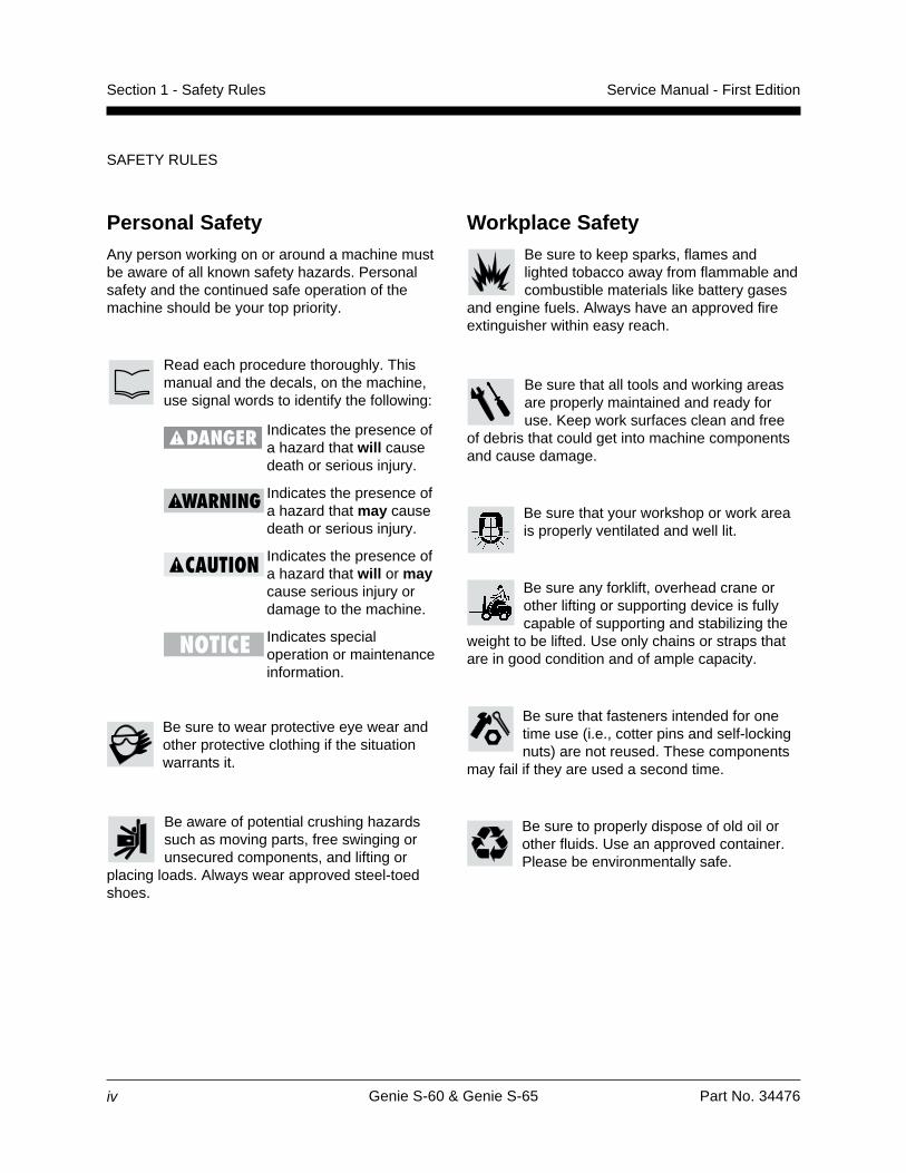
Read each procedure thoroughly. Thismanual and the decals, on the machine,use signal words to identify the following:
Indicates the presence ofa hazard that will causedeath or serious injury.
Indicates the presence ofa hazard that may causedeath or serious injury.
Indicates the presence ofa hazard that will or maycause serious injury ordamage to the machine.
Indicates specialoperation or maintenanceinformation.
Be sure to wear protective eye wear andother protective clothing if the situationwarrants it.
Be aware of potential crushing hazardssuch as moving parts, free swinging orunsecured components, and lifting or
placing loads. Always wear approved steel-toedshoes.
Part No. 34476 Genie S-60 & Genie S-65
Service Manual - First Edition
Table of Contents
v
Introduction
Important Information ..................................................................................................... ii
Section One Safety Rules
General Safety Rules .................................................................................................... iii
Section Two Specifications
Machine Specifications ............................................................................................. 2 - 1
Performance Specifications ...................................................................................... 2 - 2
Hydraulic Specifications ........................................................................................... 2 - 3
Bolt Torque Specifications ........................................................................................ 2 - 4
Ford LRG 423 Engine Specifications........................................................................ 2 - 5
Deutz F4L Engine Specifications .............................................................................. 2 - 7
Section Three Scheduled Maintenance Inspections
Introduction ............................................................................................................... 3 - 1
Table A ..................................................................................................................... 3 - 2
Table B ..................................................................................................................... 3 - 3
Table C ..................................................................................................................... 3 - 5
Table D ..................................................................................................................... 3 - 6
Maintenance Inspection Report ................................................................................ 3 - 7
Section Four Scheduled Maintenance Procedures
Introduction ............................................................................................................... 4 - 1
A-1 Inspect the Manuals ........................................................................................ 4 - 2
A-2 Inspect the Decals and Placards .................................................................... 4 - 2
A-3 Inspect for Damage, Loose or Missing Parts .................................................. 4 - 2
A-4 Check the Engine Oil Level ............................................................................. 4 - 3
A-5 Check the Engine Coolant Level - Gasoline/LPG Models ............................... 4 - 3
A-6 Check for Fuel Leaks ...................................................................................... 4 - 3
A-7 Check the Hydraulic Oil Level ......................................................................... 4 - 4
A-8 Check for Hydraulic Leaks .............................................................................. 4 - 4
Genie S-60 & Genie S-65 Part No. 34476
Service Manual - First Edition
TABLE OF CONTENTS
vi
Section Four Scheduled Maintenance Procedures, continued
A-9 Check the Tire Pressure ................................................................................. 4 - 5
A-10 Test the Oscillate Axle .................................................................................... 4 - 5
A-11 Test the Platform and Ground Controls .......................................................... 4 - 6
A-12 Test the Auxiliary Power Operation ................................................................ 4 - 6
A-13 Test the Tilt Sensor ......................................................................................... 4 - 7
A-14 Test the Limit Switches ................................................................................... 4 - 8
A-15 Replace the Engine Oil and Filter - Gasoline/LPG Models ........................... 4 - 10
A-16 Replace the Engine Air Filter ........................................................................ 4 - 11
B-1 Check the Engine Belt(s) .............................................................................. 4 - 12
B-2 Check the Radiator - Gasoline/LPG Models ................................................. 4 - 12
B-3 Check the Oil Cooler and Cooling Fins - Deutz Diesel Models ..................... 4 - 12
B-4 Check the Exhaust System ........................................................................... 4 - 13
B-5 Check the Battery ......................................................................................... 4 - 14
B-6 Check the Hydraulic Tank Filter Condition Indicator ..................................... 4 - 14
B-7 Inspect the Electrical Wiring .......................................................................... 4 - 15
B-8 Inspect the Tires and Wheels ....................................................................... 4 - 15
B-9 Confirm the Proper Brake Configuration ....................................................... 4 - 16
B-10 Check the Oil Level in the Torque Hubs ....................................................... 4 - 16
B-11 Check and Adjust the Engine Idle Mixture - Gasoline/LPG Models .............. 4 - 17
B-12 Check and Adjust the Engine RPM............................................................... 4 - 17
B-13 Test the Key Switch ...................................................................................... 4 - 19
B-14 Test the Emergency Stop Buttons ................................................................ 4 - 20
B-15 Test the Ground Control Override ................................................................. 4 - 20
B-16 Check the Directional Valve Linkage ............................................................ 4 - 21
B-17 Test the Platform Self-leveling ...................................................................... 4 - 21
B-18 Test the Service Horn ................................................................................... 4 - 21
B-19 Test the Foot Switch ..................................................................................... 4 - 22
B-20 Test the Engine Idle Select ........................................................................... 4 - 22
B-21 Test the Fuel Select Operation - Gasoline/LPG Models ............................... 4 - 23
B-22 Test the Drive Enable System ...................................................................... 4 - 23
B-23 Test the Drive Brakes ................................................................................... 4 - 24
Part No. 34476 Genie S-60 & Genie S-65
Service Manual - First Edition
TABLE OF CONTENTS
vii
Section Four Scheduled Maintenance Procedures, continued
B-24 Test the Drive Speed - Stowed Position ....................................................... 4 - 24
B-25 Test the Alarm Package - Optional Equipment ............................................. 4 - 25
B-26 Perform Hydraulic Oil Analysis ..................................................................... 4 - 25
B-27 Replace the Engine Oil and Filter - Deutz Diesel Models ............................. 4 - 26
C-1 Check the Boom Wear Pads......................................................................... 4 - 27
C-2 Check the Turntable Rotation Bearing Bolts ................................................. 4 - 27
C-3 Check the Free-wheel Configuration ............................................................ 4 - 28
C-4 Grease the Turntable Rotation Bearing and Rotate Gear ............................. 4 - 29
C-5 Replace the Torque Hub Oil ......................................................................... 4 - 29
C-6 Replace the Hydraulic Tank Filter ................................................................. 4 - 31
C-7 Replace the Drive Loop Hydraulic Filter ....................................................... 4 - 31
C-8 Replace the Diesel Fuel Filter - Deutz Diesel Models ................................... 4 - 32
C-9 Replace the Gasoline Fuel Filter - Gasoline/LPG Models ............................. 4 - 32
C-10 Replace the PCV Valve - Gasoline/LPG Models .......................................... 4 - 34
C-11 Replace the Spark Plugs - Gasoline/LPG Models ........................................ 4 - 35
C-12 Check and Adjust the Air/LPG Mixture - Gasoline/LPG Models .................... 4 - 36
C-13 Check and Adjust the Ignition Timing - Gasoline/LPG Models ...................... 4 - 37
C-14 Check the Engine Valve Clearances - Deutz Diesel Models ......................... 4 - 37
C-15 Check the Turntable Rotation Gear Backlash ............................................... 4 - 37
D-1 Test or Replace the Hydraulic Oil ................................................................. 4 - 38
D-2 Change or Recondition the Engine Coolant - Gasoline/LPG Models ............ 4 - 39
D-3 Change the Fuel Lines .................................................................................. 4 - 41
D-4 Check the Engine Valve Clearance - Gasoline/LPG Models ........................ 4 - 42
D-5 Check the Engine Cylinder Compression - Gasoline/LPG Models ............... 4 - 42
D-6 Clean the PCV Hoses and Fittings - Gasoline/LPG Models .......................... 4 - 43
D-7 Check the Fuel Injection Pumps and Injectors - Deutz Diesel Models .......... 4 - 44
D-8 Check the Toothed Belt - Deutz Diesel Models ............................................ 4 - 44
D-9 Replace the Timing Belt - Gasoline/LPG Models .......................................... 4 - 44
Genie S-60 & Genie S-65 Part No. 34476
Service Manual - First Edition
TABLE OF CONTENTS
viii
Section Five Troubleshooting Flow Charts
Introduction ............................................................................................................... 5 - 1
1 Engine Will Not Crank Over ............................................................................ 5 - 3
2 Engine Cranks Over But Will Not Start - Gasoline/LPG Models ..................... 5 - 5
3 Engine Cranks Over But Will Not Start - Deutz Diesel Models ..................... 5 - 11
4 Engine Will Not Start On LPG, But Will Start On Gasoline- Gasoline/LPG Models ................................................................................. 5 - 14
5 Engine Will Not Start On Gasoline, But Will Start On LPG- Gasoline/LPG Models ................................................................................. 5 - 16
6 Engine High Idle Inoperative - Gasoline/LPG Models ................................... 5 - 18
7 Engine Low Idle Inoperative - Gasoline/LPG Models .................................... 5 - 20
8 Engine High Idle Inoperative - Deutz Diesel Models ..................................... 5 - 21
9 Engine Low Idle Inoperative - Deutz Diesel Models ...................................... 5 - 23
10 All Functions Inoperative, Engine Starts and Runs ....................................... 5 - 24
11 All Lift and Steer Functions Inoperative, Drive Functions Operational .......... 5 - 25
12 Ground Controls Inoperative, Platform Controls Operate Normally .............. 5 - 26
13 Platform Controls Inoperative, Ground Controls Operate Normally .............. 5 - 27
14 Boom Up Function Inoperative ..................................................................... 5 - 28
15 Boom Down Function Inoperative ................................................................. 5 - 30
16 Boom Extend Function Inoperative ............................................................... 5 - 32
17 Boom Retract Function Inoperative .............................................................. 5 - 34
18 Turntable Rotate Function Inoperative .......................................................... 5 - 35
19 Turntable Rotate Left Function Inoperative ................................................... 5 - 37
20 Turntable Rotate Right Function Inoperative ................................................ 5 - 38
21 All Platform Leveling Functions Inoperative .................................................. 5 - 39
22 Platform Level Up Function Inoperative ........................................................ 5 - 40
23 Platform Level Down Function Inoperative ................................................... 5 - 41
Part No. 34476 Genie S-60 & Genie S-65
Service Manual - First Edition
TABLE OF CONTENTS
ix
Section Five Troubleshooting Flow Charts, continued
24 Platform Rotate Left Function Inoperative .................................................... 5 - 42
25 Platform Rotate Right Function Inoperative .................................................. 5 - 44
26 Jib Boom Up Inoperative - S-65 Models ....................................................... 5 - 46
27 Jib Boom Down Inoperative - S-65 Models ................................................... 5 - 48
28 Oscillate Function Inoperative ....................................................................... 5 - 50
29 Steer Left Function Inoperative ..................................................................... 5 - 51
30 Steer Right Function Inoperative .................................................................. 5 - 52
31 All Drive Functions Inoperative, All Other Functions Operate Normally ........ 5 - 53
32 Drive Forward Or Reverse Function Inoperative ........................................... 5 - 56
33 Traction Function Inoperative ....................................................................... 5 - 57
34 Machine Will Not Drive At Full Speed ........................................................... 5 - 58
35 Machine Drives At Full Speed With Platform Raised or Extended ................ 5 - 59
36 Drive Enable System Is Malfunctioning ........................................................ 5 - 60
37 Auxiliary Functions Inoperative ..................................................................... 5 - 61
Section Six Schematics
Introduction ............................................................................................................... 6 - 1
Electrical Symbols Legend ....................................................................................... 6 - 2
Electrical Schematic - Gasoline/LPG Models ........................................................... 6 - 3
Ground Control Box Legend - Gasoline/LPG Models ............................................... 6 - 5
Relay Panel Legend - Gasoline/LPG Models ........................................................... 6 - 6
Platform Control Box Legend - Gasoline/LPG Models ............................................. 6 - 7
Electrical Schematic - Diesel Models ....................................................................... 6 - 8
Ground Control Box Legend - Diesel Models ......................................................... 6 - 10
Platform Control Box Legend - Diesel Models ........................................................ 6 - 11
Hydraulic Symbols Legend ..................................................................................... 6 - 12
2WD Hydraulic Schematic - Non-oscillating axle .................................................... 6 - 13
2WD Hydraulic Schematic - Oscillating axle ........................................................... 6 - 14
4WD Hydraulic Schematic - Non-oscillating axle .................................................... 6 - 15
4WD Hydraulic Schematic - Oscillating axle ........................................................... 6 - 16
Genie S-60 & Genie S-65 Part No. 34476
Service Manual - First Edition
TABLE OF CONTENTS
x
Section Seven Repair Procedures
Introduction ............................................................................................................... 7 - 1
Platform Controls
1-1 Joystick Controllers ......................................................................................... 7 - 2
1-2 Horsepower Limiter Board .............................................................................. 7 - 6
1-3 Foot Switch ..................................................................................................... 7 - 8
1-4 Resistors ......................................................................................................... 7 - 9
1-5 Toggle Switches ............................................................................................. 7 - 9
1-6 Control Relays .............................................................................................. 7 - 10
Platform Components
2-1 Platform ........................................................................................................ 7 - 11
2-2 Platform Leveling Slave Cylinder .................................................................. 7 - 11
2-3 Platform Rotator ............................................................................................ 7 - 12
Jib Boom Components - S-65 Models
3-1 Jib Boom - S-65 Models ............................................................................... 7 - 14
3-2 Jib Boom Lift Cylinder - S-65 Models ............................................................ 7 - 15
3-3 Jib Boom / Platform Rotate Manifold Components - S-65 Models ................ 7 - 16
Boom Components
4-1 Plastic Cable Track ....................................................................................... 7 - 17
4-2 Boom ............................................................................................................ 7 - 17
4-3 Boom Lift Cylinder ........................................................................................ 7 - 20
4-4 Extension Cylinders ...................................................................................... 7 - 20
4-5 Platform Leveling Master Cylinder ................................................................ 7 - 21
Turntable Covers
5-1 Turntable Covers .......................................................................................... 7 - 22
Deutz Engine F4L 1011
6-1 RPM Adjustment ........................................................................................... 7 - 23
6-2 Flex Plate ...................................................................................................... 7 - 23
6-3 Oil Temperature and Oil Pressure Gauges ................................................... 7 - 23
Ford LRG-423 Engine
7-1 Governor Actuator ........................................................................................ 7 - 24
7-2 Choke Adjustments ....................................................................................... 7 - 25
Part No. 34476 Genie S-60 & Genie S-65
Service Manual - First Edition
TABLE OF CONTENTS
xi
Section Seven Repair Procedures, Ford LRG-423 Engine, continued
7-3 Timing Adjustment ........................................................................................ 7 - 26
7-4 Carburetor Adjustment .................................................................................. 7 - 26
7-5 RPM Adjustment ........................................................................................... 7 - 26
7-6 Flex Plate ...................................................................................................... 7 - 26
7-7 Water Temperature and Oil Pressure Gauges.............................................. 7 - 27
7-8 Vacuum Switch ............................................................................................. 7 - 27
Ground Controls
8-1 Control Relays .............................................................................................. 7 - 28
8-2 Toggle Switches, See 1-5, Toggle Switches ................................................... 7 - 9
8-3 Wago® Components...................................................................................... 7 - 29
8-4 Resistor ........................................................................................................ 7 - 29
8-5 Power Relay ................................................................................................. 7 - 30
Hydraulic Pumps
9-1 Lift/Steer Pump ............................................................................................. 7 - 31
9-2 Drive Pump ................................................................................................... 7 - 31
Function Manifolds
10-1 Function Manifolds ........................................................................................ 7 - 34
10-2 Valve Adjustments - Function Manifold ......................................................... 7 - 36
Fuel and Hydraulic Tanks
11-1 Hydraulic Tank .............................................................................................. 7 - 39
11-2 Fuel Tank ...................................................................................................... 7 - 40
Turntable Rotation Components
12-1 Rotation Hydraulic Motor .............................................................................. 7 - 41
12-2 Turntable Rotation Manifold Components .................................................... 7 - 43
2WD Steering Axle Components
13-1 Yoke and Hub ............................................................................................... 7 - 44
13-2 Steering Cylinders ........................................................................................ 7 - 45
13-3 Tie Rod ......................................................................................................... 7 - 46
Genie S-60 & Genie S-65 Part No. 34476
Service Manual - First Edition
TABLE OF CONTENTS
xii
Section Seven Repair Procedures, continued
4WD Steering Axle Components
14-1 Yoke and Hub ............................................................................................... 7 - 47
14-2 Steering Cylinders ........................................................................................ 7 - 48
14-3 Tie Rod ......................................................................................................... 7 - 48
Oscillating Axle Components
15-1 Oscillating Axle Lock-out Cylinder ................................................................ 7 - 49
Steer and Oscillate Manifolds
16-1 Oscillate Manifold Components .................................................................... 7 - 50
16-2 Valve Adjustments ........................................................................................ 7 - 51
16-3 Directional Valve Manifold Components ....................................................... 7 - 52
16-4 Steer Manifold Components ......................................................................... 7 - 54
Non-steering Axle Components
17-1 Drive Motor ................................................................................................... 7 - 55
17-2 Torque Hub ................................................................................................... 7 - 55
2WD Drive Manifold
18-1 2WD Drive Manifold Components ................................................................. 7 - 56
18-2 Valve Adjustments ........................................................................................ 7 - 57
4WD Drive Manifold
19-1 4WD Drive Manifold Components ................................................................. 7 - 58
19-2 Valve Adjustments ........................................................................................ 7 - 60
Part No. 34476 Genie S-60 & Genie S-65 2 - 1
Section 2 - SpecificationsService Manual - First Edition
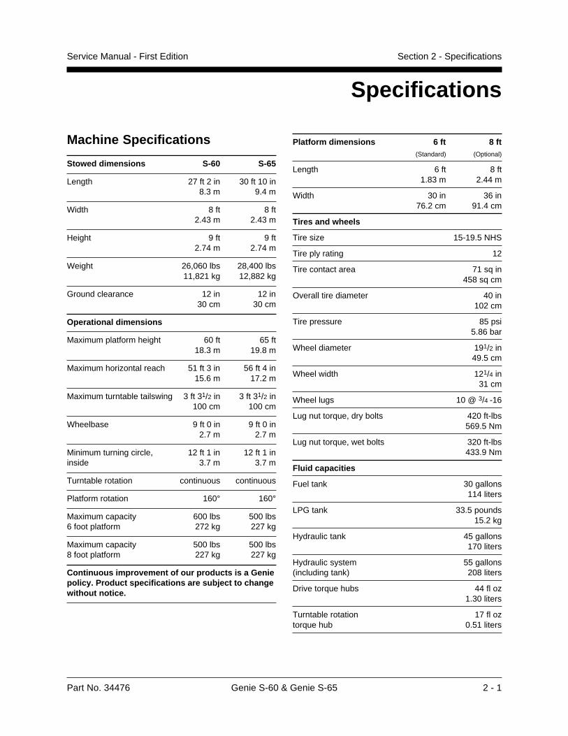
Specifications
Machine Specifications
Stowed dimensions S-60 S-65
Length 27 ft 2 in 30 ft 10 in8.3 m 9.4 m
Width 8 ft 8 ft2.43 m 2.43 m
Height 9 ft 9 ft2.74 m 2.74 m
Weight 26,060 lbs 28,400 lbs11,821 kg 12,882 kg
Ground clearance 12 in 12 in30 cm 30 cm
Operational dimensions
Maximum platform height 60 ft 65 ft18.3 m 19.8 m
Maximum horizontal reach 51 ft 3 in 56 ft 4 in15.6 m 17.2 m
Maximum turntable tailswing 3 ft 31/2 in 3 ft 31/2 in100 cm 100 cm
Wheelbase 9 ft 0 in 9 ft 0 in2.7 m 2.7 m
Minimum turning circle, 12 ft 1 in 12 ft 1 ininside 3.7 m 3.7 m
Turntable rotation continuous continuous
Platform rotation 160° 160°
Maximum capacity 600 lbs 500 lbs6 foot platform 272 kg 227 kg
Maximum capacity 500 lbs 500 lbs8 foot platform 227 kg 227 kg
Continuous improvement of our products is a Geniepolicy. Product specifications are subject to changewithout notice.
Platform dimensions 6 ft 8 ft(Standard) (Optional)
Length 6 ft 8 ft1.83 m 2.44 m
Width 30 in 36 in76.2 cm 91.4 cm
Tires and wheels
Tire size 15-19.5 NHS
Tire ply rating 12
Tire contact area 71 sq in458 sq cm
Overall tire diameter 40 in102 cm
Tire pressure 85 psi5.86 bar
Wheel diameter 191/2 in49.5 cm
Wheel width 121/4 in31 cm
Wheel lugs 10 @ 3/4 -16
Lug nut torque, dry bolts 420 ft-lbs569.5 Nm
Lug nut torque, wet bolts 320 ft-lbs433.9 Nm
Fluid capacities
Fuel tank 30 gallons114 liters
LPG tank 33.5 pounds15.2 kg
Hydraulic tank 45 gallons170 liters
Hydraulic system 55 gallons(including tank) 208 liters
Drive torque hubs 44 fl oz1.30 liters
Turntable rotation 17 fl oztorque hub 0.51 liters
2 - 2 Genie S-60 & Genie S-65 Part No. 34476
Section 2 - Specifications Service Manual - First Edition
PERFORMANCE SPECIFICATIONS
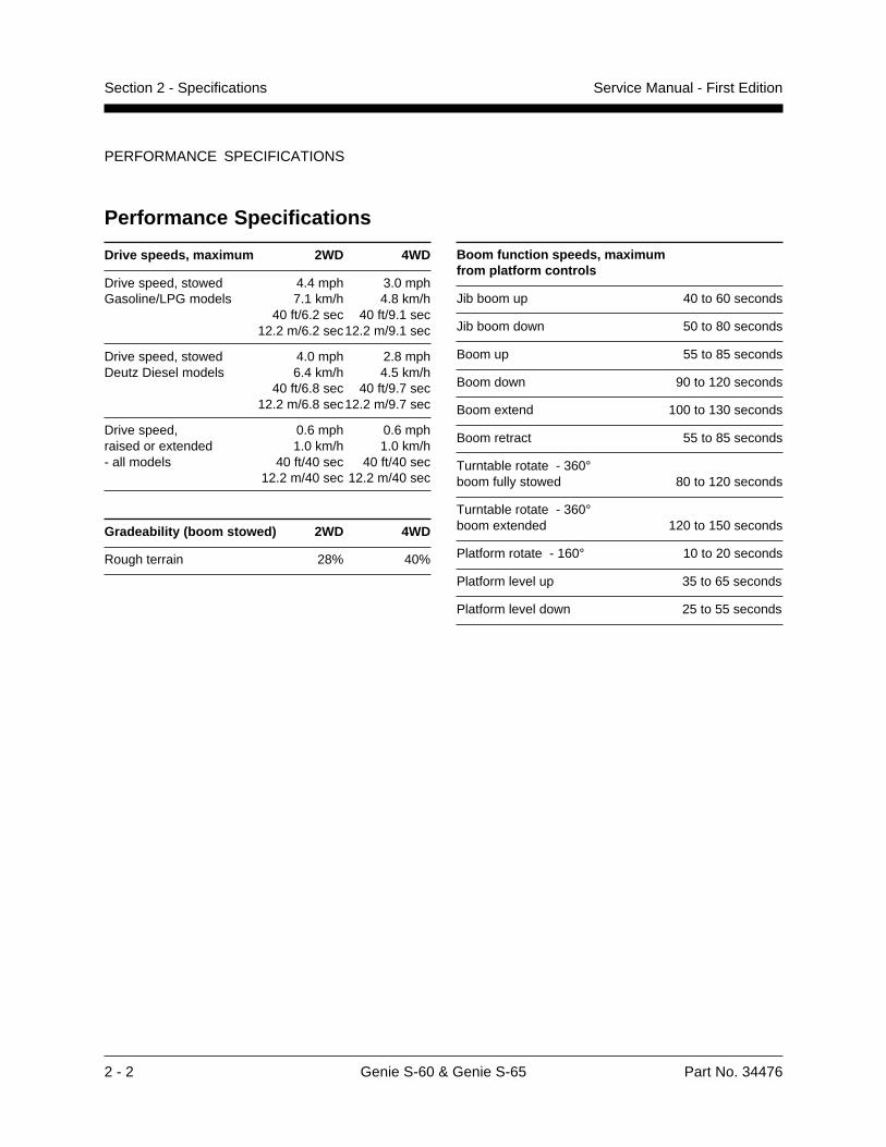
Boom function speeds, maximumfrom platform controls
Jib boom up 40 to 60 seconds
Jib boom down 50 to 80 seconds
Boom up 55 to 85 seconds
Boom down 90 to 120 seconds
Boom extend 100 to 130 seconds
Boom retract 55 to 85 seconds
Turntable rotate - 360°boom fully stowed 80 to 120 seconds
Turntable rotate - 360°boom extended 120 to 150 seconds
Platform rotate - 160° 10 to 20 seconds
Platform level up 35 to 65 seconds
Platform level down 25 to 55 seconds
Performance Specifications
Drive speeds, maximum 2WD 4WD
Drive speed, stowed 4.4 mph 3.0 mphGasoline/LPG models 7.1 km/h 4.8 km/h
40 ft/6.2 sec 40 ft/9.1 sec12.2 m/6.2 sec12.2 m/9.1 sec
Drive speed, stowed 4.0 mph 2.8 mphDeutz Diesel models 6.4 km/h 4.5 km/h
40 ft/6.8 sec 40 ft/9.7 sec12.2 m/6.8 sec12.2 m/9.7 sec
Drive speed, 0.6 mph 0.6 mphraised or extended 1.0 km/h 1.0 km/h- all models 40 ft/40 sec 40 ft/40 sec
12.2 m/40 sec 12.2 m/40 sec
Gradeability (boom stowed) 2WD 4WD
Rough terrain 28% 40%
Part No. 34476 Genie S-60 & Genie S-65 2 - 3
Section 2 - SpecificationsService Manual - First Edition
HYDRAULIC SPECIFICATIONS
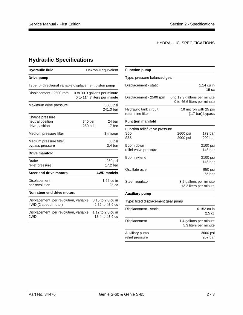
Hydraulic Specifications
Hydraulic fluid Dexron II equivalent
Drive pump
Type: bi-directional variable displacement piston pump
Displacement - 2500 rpm 0 to 30.3 gallons per minute0 to 114.7 liters per minute
Maximum drive pressure 3500 psi241.3 bar
Charge pressureneutral position 340 psi 24 bardrive position 250 psi 17 bar
Medium pressure filter 3 micron
Medium pressure filter 50 psibypass pressure 3.4 bar
Drive manifold
Brake 250 psirelief pressure 17.2 bar
Steer end drive motors 4WD models
Displacement 1.52 cu inper revolution 25 cc
Non-steer end drive motors
Displacement per revolution, variable 0.16 to 2.8 cu in4WD (2 speed motor) 2.62 to 45.9 cc
Displacement per revolution, variable 1.12 to 2.8 cu in2WD 18.4 to 45.9 cc
Function pump
Type: pressure balanced gear
Displacement - static 1.14 cu in19 cc
Displacement - 2500 rpm 0 to 12.3 gallons per minute0 to 46.6 liters per minute
Hydraulic tank circuit 10 micron with 25 psireturn line filter (1.7 bar) bypass
Function manifold
Function relief valve pressureS60 2600 psi 179 barS65 2900 psi 200 bar
Boom down 2100 psirelief valve pressure 145 bar
Boom extend 2100 psi145 bar
Oscillate axle 950 psi65 bar
Steer regulator 3.5 gallons per minute13.2 liters per minute
Auxiliary pump
Type: fixed displacement gear pump
Displacement - static 0.152 cu in2.5 cc
Displacement 1.4 gallons per minute5.3 liters per minute
Auxiliary pump 3000 psirelief pressure 207 bar
2 - 4 Genie S-60 & Genie S-65 Part No. 34476
Section 2 - Specifications Service Manual - First Edition
BOLT TORQUE SPECIFICATIONS
24
32
20
28
18
24
16
24
14
20
Torque - Dry
inch-pounds
Torque - Dry
foot-pounds
Torque - Dry
Newton meters
Torque - Dry
inch-pounds
Torque - Dry
foot-pounds
Torque - Dry
Newton meters
43
49
96
120
17
19
30
35
50
55
75
90
110
120
150
170
260
300
430
470
640
700
5
6
11
14
23
28
41
48
68
75
102
122
149
163
204
231
353
407
583
637
868
949
60
68
144
168
25
25
45
50
70
80
110
120
150
170
220
240
380
420
600
660
900
1000
7
8
16
19
34
34
61
68
95
109
149
163
204
231
298
326
515
570
814
895
1221
1356
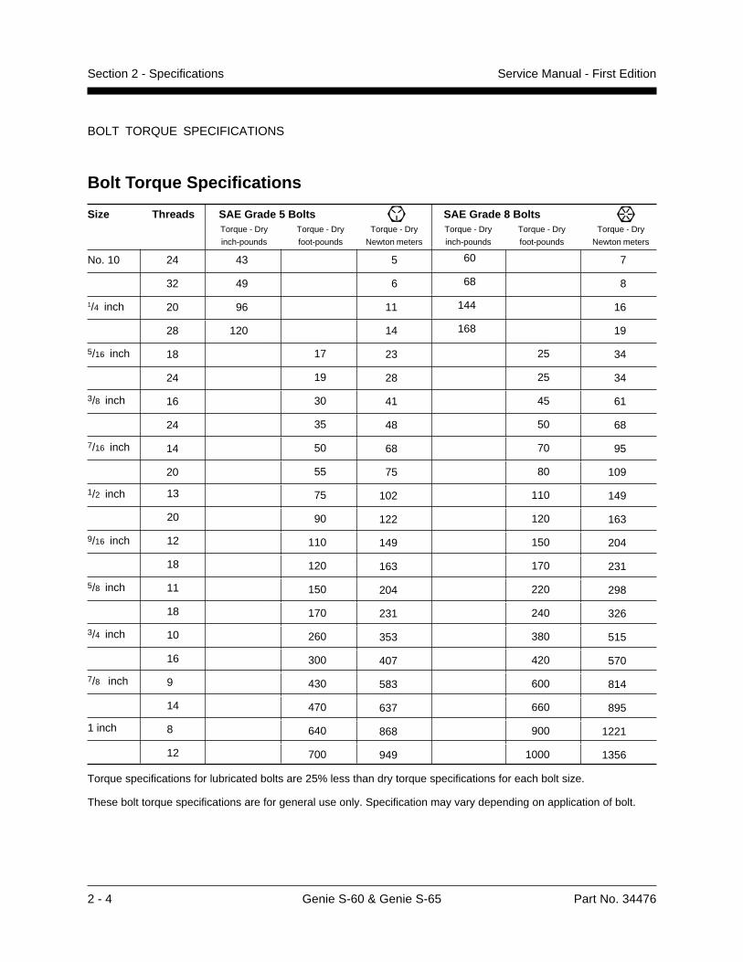
Size Threads SAE Grade 5 Bolts SAE Grade 8 Bolts
Bolt Torque Specifications
13
20
12
18
11
18
10
16
9
14
8
12
No. 10
1/4 inch
5/16 inch
3/8 inch
7/16 inch
1/2 inch
9/16 inch
5/8 inch
3/4 inch
7/8 inch
1 inch
Torque specifications for lubricated bolts are 25% less than dry torque specifications for each bolt size.
These bolt torque specifications are for general use only. Specification may vary depending on application of bolt.
Part No. 34476 Genie S-60 & Genie S-65 2 - 5
Section 2 - SpecificationsService Manual - First Edition
FORD ENGINE LRG-423 SPECIFICATIONS
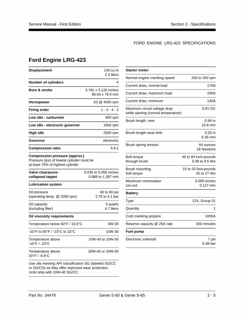
Ford Engine LRG-423
Displacement 140 cu in2.3 liters
Number of cylinders 4
Bore & stroke 3.781 x 3.126 inches96.04 x 79.4 mm
Horsepower 63 @ 4000 rpm
Firing order 1 - 3 - 4 - 2
Low idle - carburetor 900 rpm
Low idle - electronic governor 1600 rpm
High idle 2500 rpm
Governor electronic
Compression ratio 9.4:1
Compression pressure (approx.)Pressure (psi) of lowest cylinder must beat least 75% of highest cylinder
Valve clearances - 0.035 to 0.055 inchescollapsed tappet 0.889 to 1.397 mm
Lubrication system
Oil pressure 40 to 60 psi(operating temp. @ 2000 rpm) 2.75 to 4.1 bar
Oil capacity 5 quarts(including filter) 4.7 liters
Oil viscosity requirements
Temperature below 60°F / 15.5°C 5W-30
-10°F to 90°F / -23°C to 32°C 10W-30
Temperature above 10W-40 to 10W-50-10°F / -23°C
Temperature above 20W-40 or 20W-5020°F / -6.6°C
Use oils meeting API classification SG (labeled SG/CCor SG/CD) as they offer improved wear protection.Units ship with 10W-40 SG/CC.
Starter motor
Normal engine cranking speed 200 to 250 rpm
Current draw, normal load 170A
Current draw, maximum load 200A
Current draw, minimum 140A
Maximum circuit voltage drop 0.5V DCwhile starting (normal temperature)
Brush length, new 0.66 in16.8 mm
Brush length wear limit 0.25 in6.35 mm
Brush spring tension 64 ounces18 Newtons
Bolt torque 45 to 84 inch-poundsthrough brush 5.08 to 9.5 Nm
Brush mounting 15 to 20 foot-poundsbolt torque 20 to 27 Nm
Maximum commutator 0.005 inchesrun-out 0.127 mm
Battery
Type 12V, Group 31
Quantity 1
Cold cranking ampere 1000A
Reserve capacity @ 25A rate 200 minutes
Fuel pump
Electronic solenoid 7 psi0.48 bar
2 - 6 Genie S-60 & Genie S-65 Part No. 34476
Section 2 - Specifications Service Manual - First Edition
FORD ENGINE LRG-423 SPECIFICATIONS
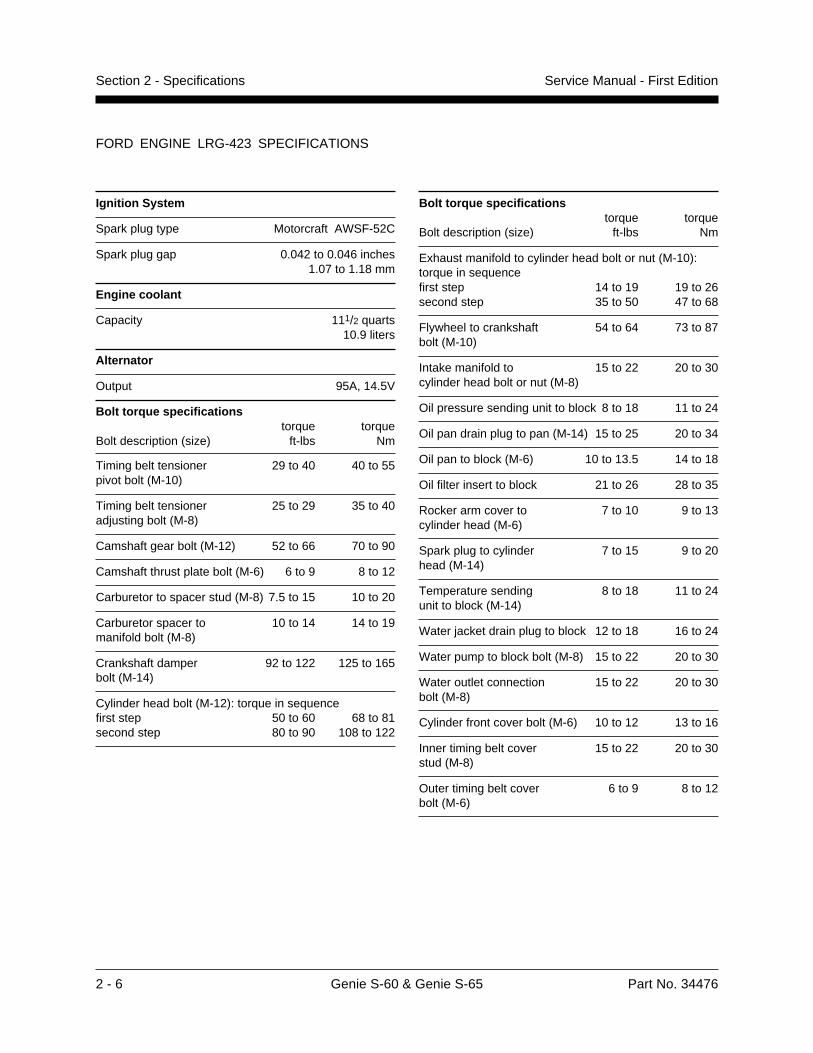
Ignition System
Spark plug type Motorcraft AWSF-52C
Spark plug gap 0.042 to 0.046 inches1.07 to 1.18 mm
Engine coolant
Capacity 111/2 quarts10.9 liters
Alternator
Output 95A, 14.5V
Bolt torque specificationstorque torque
Bolt description (size) ft-lbs Nm
Timing belt tensioner 29 to 40 40 to 55pivot bolt (M-10)
Timing belt tensioner 25 to 29 35 to 40adjusting bolt (M-8)
Camshaft gear bolt (M-12) 52 to 66 70 to 90
Camshaft thrust plate bolt (M-6) 6 to 9 8 to 12
Carburetor to spacer stud (M-8) 7.5 to 15 10 to 20
Carburetor spacer to 10 to 14 14 to 19manifold bolt (M-8)
Crankshaft damper 92 to 122 125 to 165bolt (M-14)
Cylinder head bolt (M-12): torque in sequencefirst step 50 to 60 68 to 81second step 80 to 90 108 to 122
Bolt torque specificationstorque torque
Bolt description (size) ft-lbs Nm
Exhaust manifold to cylinder head bolt or nut (M-10):torque in sequencefirst step 14 to 19 19 to 26second step 35 to 50 47 to 68
Flywheel to crankshaft 54 to 64 73 to 87bolt (M-10)
Intake manifold to 15 to 22 20 to 30cylinder head bolt or nut (M-8)
Oil pressure sending unit to block 8 to 18 11 to 24
Oil pan drain plug to pan (M-14) 15 to 25 20 to 34
Oil pan to block (M-6) 10 to 13.5 14 to 18
Oil filter insert to block 21 to 26 28 to 35
Rocker arm cover to 7 to 10 9 to 13cylinder head (M-6)
Spark plug to cylinder 7 to 15 9 to 20head (M-14)
Temperature sending 8 to 18 11 to 24unit to block (M-14)
Water jacket drain plug to block 12 to 18 16 to 24
Water pump to block bolt (M-8) 15 to 22 20 to 30
Water outlet connection 15 to 22 20 to 30bolt (M-8)
Cylinder front cover bolt (M-6) 10 to 12 13 to 16
Inner timing belt cover 15 to 22 20 to 30stud (M-8)
Outer timing belt cover 6 to 9 8 to 12bolt (M-6)
Part No. 34476 Genie S-60 & Genie S-65 2 - 7
Section 2 - SpecificationsService Manual - First Edition
DEUTZ ENGINE F4L 1011 SPECIFICATIONS
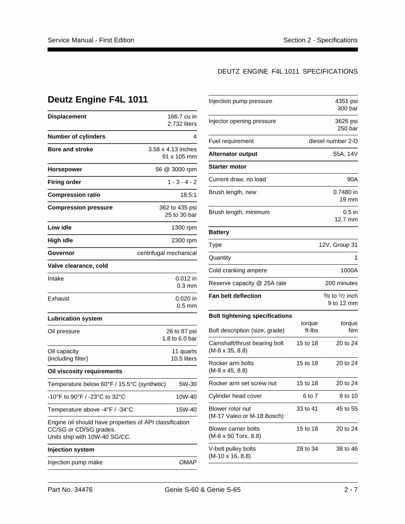
Injection pump pressure 4351 psi300 bar
Injector opening pressure 3626 psi250 bar
Fuel requirement diesel number 2-D
Alternator output 55A, 14V
Starter motor
Current draw, no load 90A
Brush length, new 0.7480 in19 mm
Brush length, minimum 0.5 in12.7 mm
Battery
Type 12V, Group 31
Quantity 1
Cold cranking ampere 1000A
Reserve capacity @ 25A rate 200 minutes
Fan belt deflection 3/8 to 1/2 inch9 to 12 mm
Bolt tightening specificationstorque torque
Bolt description (size, grade) ft-lbs Nm
Camshaft/thrust bearing bolt 15 to 18 20 to 24(M-8 x 35, 8.8)
Rocker arm bolts 15 to 18 20 to 24(M-8 x 45, 8.8)
Rocker arm set screw nut 15 to 18 20 to 24
Cylinder head cover 6 to 7 8 to 10
Blower rotor nut 33 to 41 45 to 55(M-17 Valeo or M-18 Bosch)
Blower carrier bolts 15 to 18 20 to 24(M-8 x 50 Torx, 8.8)
V-belt pulley bolts 28 to 34 38 to 46(M-10 x 16, 8.8)
Deutz Engine F4L 1011
Displacement 166.7 cu in2.732 liters
Number of cylinders 4
Bore and stroke 3.58 x 4.13 inches91 x 105 mm
Horsepower 56 @ 3000 rpm
Firing order 1 - 3 - 4 - 2
Compression ratio 18.5:1
Compression pressure 362 to 435 psi25 to 30 bar
Low idle 1300 rpm
High idle 2300 rpm
Governor centrifugal mechanical
Valve clearance, cold
Intake 0.012 in0.3 mm
Exhaust 0.020 in0.5 mm
Lubrication system
Oil pressure 26 to 87 psi1.8 to 6.0 bar
Oil capacity 11 quarts(including filter) 10.5 liters
Oil viscosity requirements
Temperature below 60°F / 15.5°C (synthetic) 5W-30
-10°F to 90°F / -23°C to 32°C 10W-40
Temperature above -4°F / -34°C 15W-40
Engine oil should have properties of API classificationCC/SG or CD/SG grades.Units ship with 10W-40 SG/CC.
Injection system
Injection pump make OMAP
2 - 8 Genie S-60 & Genie S-65 Part No. 34476
Section 2 - Specifications Service Manual - First Edition
DEUTZ ENGINE F4L 1011 SPECIFICATIONS
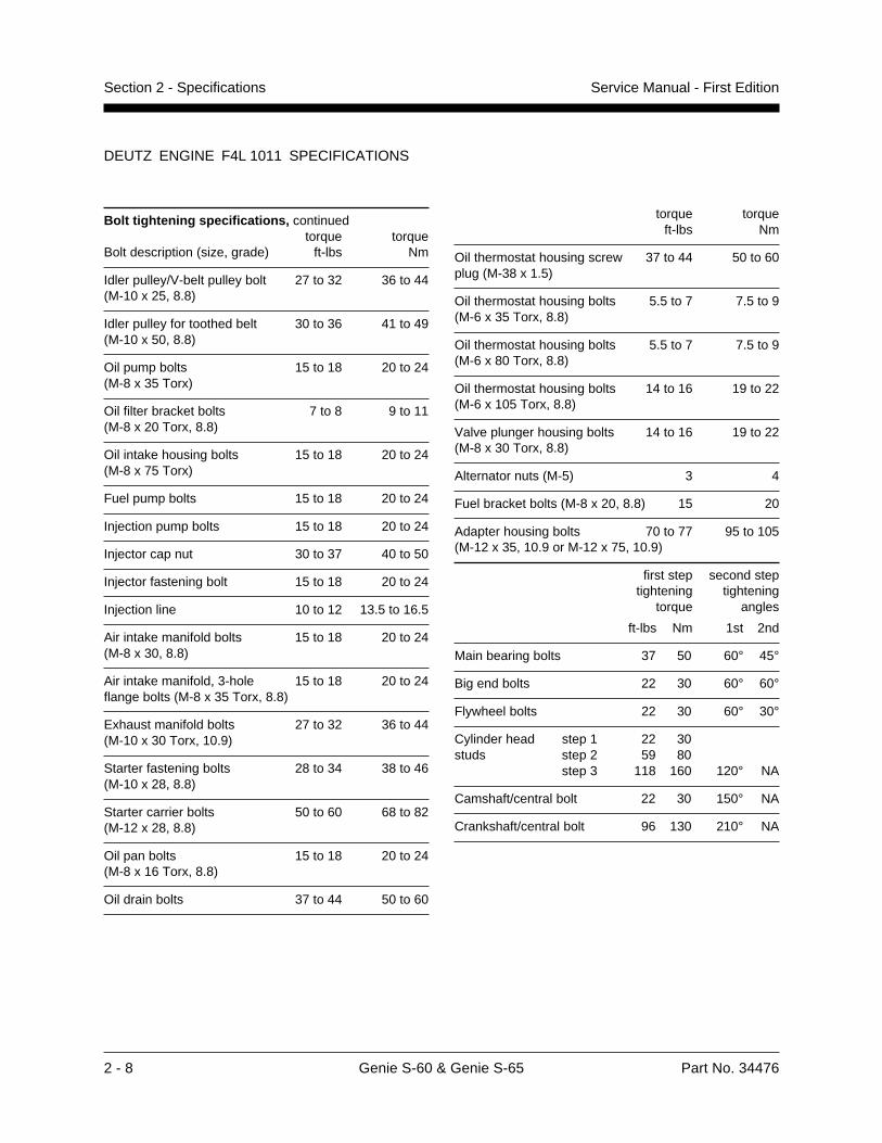
Bolt tightening specifications, continuedtorque torque
Bolt description (size, grade) ft-lbs Nm
Idler pulley/V-belt pulley bolt 27 to 32 36 to 44(M-10 x 25, 8.8)
Idler pulley for toothed belt 30 to 36 41 to 49(M-10 x 50, 8.8)
Oil pump bolts 15 to 18 20 to 24(M-8 x 35 Torx)
Oil filter bracket bolts 7 to 8 9 to 11(M-8 x 20 Torx, 8.8)
Oil intake housing bolts 15 to 18 20 to 24(M-8 x 75 Torx)
Fuel pump bolts 15 to 18 20 to 24
Injection pump bolts 15 to 18 20 to 24
Injector cap nut 30 to 37 40 to 50
Injector fastening bolt 15 to 18 20 to 24
Injection line 10 to 12 13.5 to 16.5
Air intake manifold bolts 15 to 18 20 to 24(M-8 x 30, 8.8)
Air intake manifold, 3-hole 15 to 18 20 to 24flange bolts (M-8 x 35 Torx, 8.8)
Exhaust manifold bolts 27 to 32 36 to 44(M-10 x 30 Torx, 10.9)
Starter fastening bolts 28 to 34 38 to 46(M-10 x 28, 8.8)
Starter carrier bolts 50 to 60 68 to 82(M-12 x 28, 8.8)
Oil pan bolts 15 to 18 20 to 24(M-8 x 16 Torx, 8.8)
Oil drain bolts 37 to 44 50 to 60
torque torqueft-lbs Nm
Oil thermostat housing screw 37 to 44 50 to 60plug (M-38 x 1.5)
Oil thermostat housing bolts 5.5 to 7 7.5 to 9(M-6 x 35 Torx, 8.8)
Oil thermostat housing bolts 5.5 to 7 7.5 to 9(M-6 x 80 Torx, 8.8)
Oil thermostat housing bolts 14 to 16 19 to 22(M-6 x 10⁵ Torx, 8.8)
Valve plunger housing bolts 14 to 16 19 to 22(M-8 x 30 Torx, 8.8)
Alternator nuts (M-5) 3 4
Fuel bracket bolts (M-8 x 20, 8.8) 15 20
Adapter housing bolts 70 to 77 95 to 105(M-12 x 35, 10.9 or M-12 x 75, 10.9)
first step second steptightening tightening
torque angles
ft-lbs Nm 1st 2nd
Main bearing bolts 37 50 60° 45°
Big end bolts 22 30 60° 60°
Flywheel bolts 22 30 60° 30°
Cylinder head step 1 22 30studs step 2 59 80
step 3 118 160 120° NA
Camshaft/central bolt 22 30 150° NA
Crankshaft/central bolt 96 130 210° NA
Part No. 34476 Genie S-60 & Genie S-65 3 - 1
Section 3 - Scheduled Maintenance InspectionsService Manual - First Edition
Tools arerequired
New partsrequired
Warmengine
required
Coldengine
required
Dealerservice
suggested
Scheduled Maintenance Inspections
Observe and Obey:
Maintenance inspections shall be completed bya person trained and qualified on themaintenance of this machine.
Scheduled maintenance inspections shall becompleted daily, quarterly, annually and every2 years as specified on the MaintenanceInspection Report.
Failure to properly complete eachinspection when required maycause death, serious injury orsubstantial damage.
Immediately tag and remove from service adamaged or malfunctioning machine.
Repair any machine damage or malfunctionbefore operating machine.
Keep records on all inspections for three years.
Machines that have been out of service for aperiod longer than 3 months must complete thequarterly inspection.
About This SectionThe Schedule
There are four types of maintenance inspectionsthat must be performed according to a schedule—daily, quarterly, annual, two year. To account forrepeated procedures, the Maintenance Tables andthe Maintenance Inspection Report have beendivided into four subsections—A, B, C, D. Use thefollowing chart to determine which group(s) ofprocedures are required to perform a scheduledinspection.
Inspection Table or Checklist
Daily A
Quarterly A + B
Annual A + B + C
Two year A + B + C + D
Maintenance Tables
The maintenance tables contained in this sectionprovide summary information on the specificphysical requirements for each inspection.
Complete step-by-step instructions for eachscheduled maintenance procedure are provided insection 4, Scheduled Maintenance Procedures.
Maintenance Inspection Report
The maintenance inspection report containschecklists for each type of scheduled inspection.
Make copies of the Maintenance InspectionReport to use for each inspection. Storecompleted forms for three years.
3 - 2 Genie S-60 & Genie S-65 Part No. 34476
Section 3 - Scheduled Maintenance Inspections Service Manual - First Edition
Tools arerequired
New partsrequired
Warmengine
required
Coldengine
required
Dealerservice
suggested
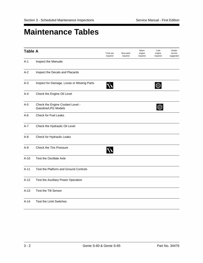
Table A
A-1 Inspect the Manuals
A-2 Inspect the Decals and Placards
A-3 Inspect for Damage, Loose or Missing Parts
A-4 Check the Engine Oil Level
A-5 Check the Engine Coolant Level -Gasoline/LPG Models
A-6 Check for Fuel Leaks
A-7 Check the Hydraulic Oil Level
A-8 Check for Hydraulic Leaks
A-9 Check the Tire Pressure
A-10 Test the Oscillate Axle
A-11 Test the Platform and Ground Controls
A-12 Test the Auxiliary Power Operation
A-13 Test the Tilt Sensor
A-14 Test the Limit Switches
Maintenance Tables
Part No. 34476 Genie S-60 & Genie S-65 3 - 3
Section 3 - Scheduled Maintenance InspectionsService Manual - First Edition
Tools arerequired
New partsrequired
Warmengine
required
Coldengine
required
Dealerservice
suggested
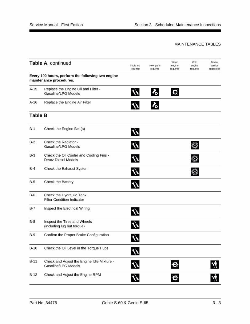
Table A, continued
Every 100 hours, perform the following two enginemaintenance procedures.
A-15 Replace the Engine Oil and Filter -Gasoline/LPG Models
A-16 Replace the Engine Air Filter
Table B
B-1 Check the Engine Belt(s)
B-2 Check the Radiator -Gasoline/LPG Models
B-3 Check the Oil Cooler and Cooling Fins -Deutz Diesel Models
B-4 Check the Exhaust System
B-5 Check the Battery
B-6 Check the Hydraulic TankFilter Condition Indicator
B-7 Inspect the Electrical Wiring
B-8 Inspect the Tires and Wheels(including lug nut torque)
B-9 Confirm the Proper Brake Configuration
B-10 Check the Oil Level in the Torque Hubs
B-11 Check and Adjust the Engine Idle Mixture -Gasoline/LPG Models
B-12 Check and Adjust the Engine RPM
MAINTENANCE TABLES
3 - 4 Genie S-60 & Genie S-65 Part No. 34476
Section 3 - Scheduled Maintenance Inspections Service Manual - First Edition
Tools arerequired
New partsrequired
Warmengine
required
Coldengine
required
Dealerservice
suggested
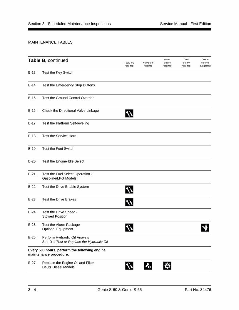
Table B, continued
B-13 Test the Key Switch
B-14 Test the Emergency Stop Buttons
B-15 Test the Ground Control Override
B-16 Check the Directional Valve Linkage
B-17 Test the Platform Self-leveling
B-18 Test the Service Horn
B-19 Test the Foot Switch
B-20 Test the Engine Idle Select
B-21 Test the Fuel Select Operation -Gasoline/LPG Models
B-22 Test the Drive Enable System
B-23 Test the Drive Brakes
B-24 Test the Drive Speed -Stowed Position
B-25 Test the Alarm Package -Optional Equipment
B-26 Perform Hydraulic Oil AnaysisSee D-1 Test or Replace the Hydraulic Oil
Every 500 hours, perform the following enginemaintenance procedure.
B-27 Replace the Engine Oil and Filter -Deutz Diesel Models
MAINTENANCE TABLES
Part No. 34476 Genie S-60 & Genie S-65 3 - 5
Section 3 - Scheduled Maintenance InspectionsService Manual - First Edition
Tools arerequired
New partsrequired
Warmengine
required
Coldengine
required
Dealerservice
suggested
MAINTENANCE TABLES
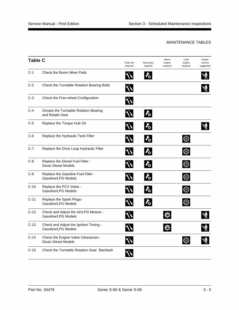
Table C
C-1 Check the Boom Wear Pads
C-2 Check the Turntable Rotation Bearing Bolts
C-3 Check the Free-wheel Configuration
C-4 Grease the Turntable Rotation Bearingand Rotate Gear
C-5 Replace the Torque Hub Oil
C-6 Replace the Hydraulic Tank Filter
C-7 Replace the Drive Loop Hydraulic Filter
C-8 Replace the Diesel Fuel Filter -Deutz Diesel Models
C-9 Replace the Gasoline Fuel Filter -Gasoline/LPG Models
C-10 Replace the PCV Valve -Gasoline/LPG Models
C-11 Replace the Spark Plugs -Gasoline/LPG Models
C-12 Check and Adjust the Air/LPG Mixture -Gasoline/LPG Models
C-13 Check and Adjust the Ignition Timing -Gasoline/LPG Models
C-14 Check the Engine Valve Clearances -Deutz Diesel Models
C-15 Check the Turntable Rotation Gear Backlash
3 - 6 Genie S-60 & Genie S-65 Part No. 34476
Section 3 - Scheduled Maintenance Inspections Service Manual - First Edition
Tools arerequired
New partsrequired
Warmengine
required
Coldengine
required
Dealerservice
suggested
MAINTENANCE TABLES
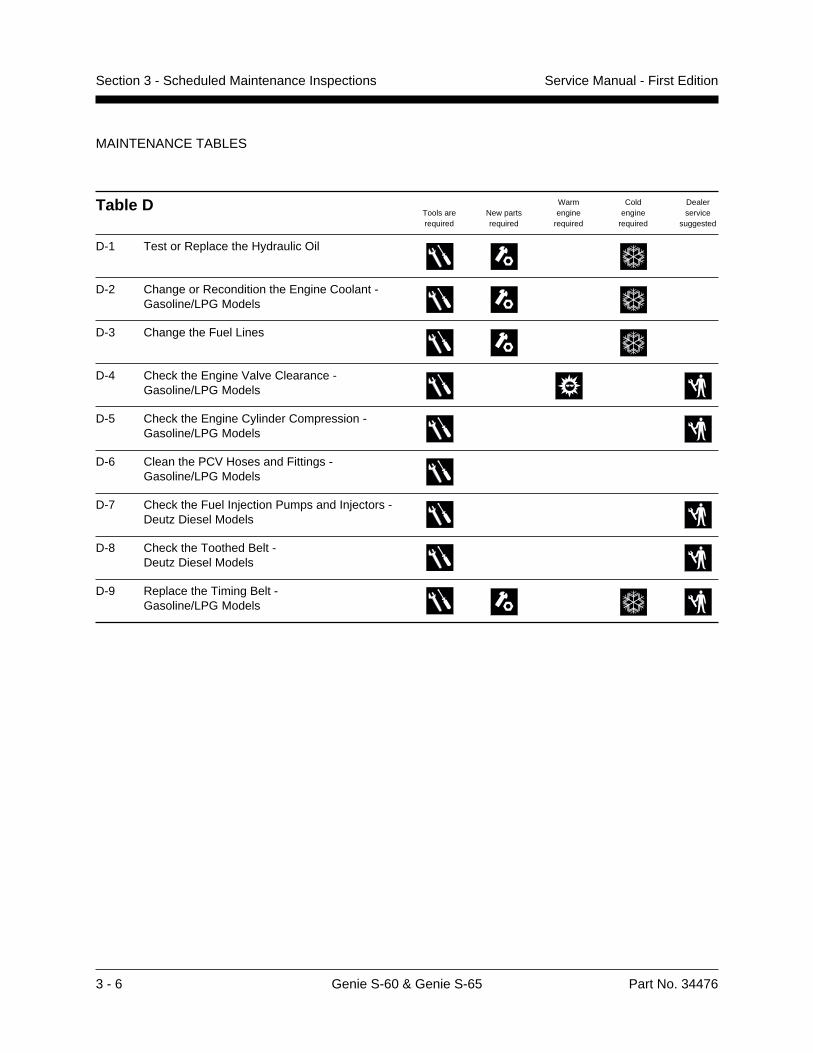
Table D
D-1 Test or Replace the Hydraulic Oil
D-2 Change or Recondition the Engine Coolant -Gasoline/LPG Models
D-3 Change the Fuel Lines
D-4 Check the Engine Valve Clearance -Gasoline/LPG Models
D-5 Check the Engine Cylinder Compression -Gasoline/LPG Models
D-6 Clean the PCV Hoses and Fittings -Gasoline/LPG Models
D-7 Check the Fuel Injection Pumps and Injectors -Deutz Diesel Models
D-8 Check the Toothed Belt -Deutz Diesel Models
D-9 Replace the Timing Belt -Gasoline/LPG Models
Part No. 34476 Genie S-60 & Genie S-65 3 - 7
Section 3 - Scheduled Maintenance InspectionsService Manual - First Edition
Tools arerequired
New partsrequired
Warmengine
required
Coldengine
required
Dealerservice
suggested
B-19 Foot switch
B-20 Engine idle select
B-21 Fuel select-gasoline
B-22 Drive enable system
B-23 Drive brakes
B-24 Drive speed-stowed
B-25 Alarm package
B-26 Hydraulic oil analysis
Perform every 500 hours:
B-27 Replace engine oiland filter-Deutz
Checklist C Y N R
Refer to Table C
C-1 Boom wear pads
C-2 Turntable bearing bolts
C-3 Free-wheel configuration
C-4 Grease rotation bearing
C-5 Torque hub oil
C-6 Hydraulic tank filter
C-7 Drive loop hydraulic filter
C-8 Fuel filter-diesel
C-9 Fuel filter-gasoline
C-10 PCV valve-gasoline
C-11 Spark plugs-gasoline
C-12 Air/LPG mixture
C-13 Ignition timing-gasoline
C-14 Valves-Deutz
C-15 Turntable backlash
Checklist D Y N R
Refer to Table D
D-1 Hydraulic oil
D-2 Engine coolant-gasoline
D-3 Change fuel lines
D-4 Valves-gasoline
D-5 Compression-gasoline
D-6 PCV hoses-gasoline
D-7 Fuel injection-Deutz
D-8 Toothed belt-Deutz
D-9 Timing belt-Ford
Checklist A Y N R
Refer to Table A
A-1 Manuals
A-2 Decals and placards
A-3 Damage, loose ormissing parts
A-4 Engine oil level
A-5 Engine coolant-gasoline
A-6 Fuel leaks
A-7 Hydraulic oil level
A-8 Hydraulic leaks
A-9 Tire pressure
A-10 Oscillate axle
A-11 Platform andground controls
A-12 Auxiliary power
A-13 Tilt sensor
A-14 Limit switches
Perform every 100 hours:
A-15 Replace engine oiland filter-gasoline
A-16 Replace air filter
Checklist B Y N R
Refer to Table B
B-1 Engine belt(s)
B-2 Engine radiator
B-3 Oil cooler and fins-Deutz
B-4 Exhaust system
B-5 Battery
B-6 Hydraulic tank filter
B-7 Electrical wiring
B-8 Tires and wheels
B-9 Brake configuration
B-10 Torque hub oil level
B-11 Idle mixture-gasoline
B-12 Engine RPM
B-13 Key switch
B-14 Emergency Stop
B-15 Ground control override
B-16 Directional valve
B-17 Platform leveling
B-18 Service horn
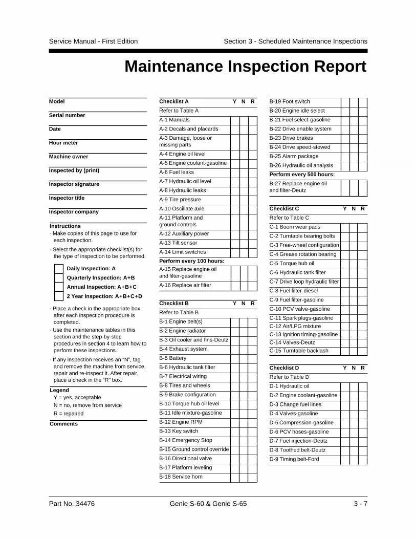
Instructions· Make copies of this page to use for
each inspection.
· Select the appropriate checklist(s) forthe type of inspection to be performed.
Daily Inspection: A
Quarterly Inspection: A+B
Annual Inspection: A+B+C
2 Year Inspection: A+B+C+D
· Place a check in the appropriate boxafter each inspection procedure iscompleted.
· Use the maintenance tables in thissection and the step-by-stepprocedures in section 4 to learn how toperform these inspections.
· If any inspection receives an “N”, tagand remove the machine from service,repair and re-inspect it. After repair,place a check in the “R” box.
LegendY = yes, acceptableN = no, remove from service
R = repaired
Comments
Maintenance Inspection Report
Model
Serial number
Date
Hour meter
Machine owner
Inspected by (print)
Inspector signature
Inspector title
Inspector company

3 - 8 Genie S-60 & Genie S-65 Part No. 34476
Section 3 - Scheduled Maintenance Inspections Service Manual - First Edition
Tools arerequired
New partsrequired
Warmengine
required
Coldengine
required
Dealerservice
suggested
This page intentionally left blank.
Part No. 34476 Genie S-60 & Genie S-65 4 - 1
Service Manual - First Edition Section 4 - Scheduled Maintenance Procedures
Scheduled Maintenance Procedures
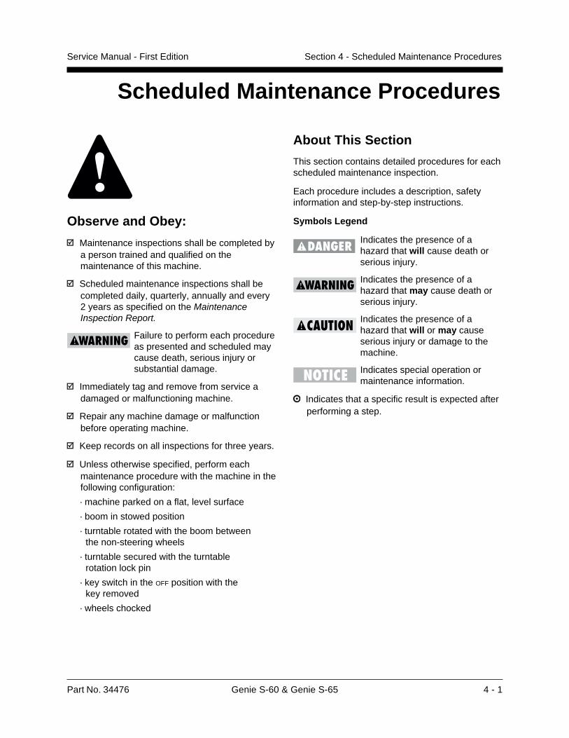
About This Section
This section contains detailed procedures for eachscheduled maintenance inspection.
Each procedure includes a description, safetyinformation and step-by-step instructions.
Symbols Legend
Indicates the presence of ahazard that will cause death orserious injury.
Indicates the presence of ahazard that may cause death orserious injury.
Indicates the presence of ahazard that will or may causeserious injury or damage to themachine.
Indicates special operation ormaintenance information.
Indicates that a specific result is expected afterperforming a step.
Observe and Obey:
Maintenance inspections shall be completed bya person trained and qualified on themaintenance of this machine.
Scheduled maintenance inspections shall becompleted daily, quarterly, annually and every2 years as specified on the MaintenanceInspection Report.
Failure to perform each procedureas presented and scheduled maycause death, serious injury orsubstantial damage.
Immediately tag and remove from service adamaged or malfunctioning machine.
Repair any machine damage or malfunctionbefore operating machine.
Keep records on all inspections for three years.
Unless otherwise specified, perform eachmaintenance procedure with the machine in thefollowing configuration:
· machine parked on a flat, level surface
· boom in stowed position
· turntable rotated with the boom between the non-steering wheels
· turntable secured with the turntable rotation lock pin
· key switch in the OFF position with the key removed
· wheels chocked
4 - 2 Genie S-60 & Genie S-65 Part No. 34476
Service Manual - First EditionSection 4 - Scheduled Maintenance Procedures
A-1Inspect the ManualsMaintaining the operator’s and safety manuals ingood condition is essential to safe machineoperation. Manuals are included with eachmachine and should be stored in the containerprovided in the platform. An illegible or missingmanual will not provide safety and operationalinformation necessary for a safe operatingcondition.
1 Check to be sure that the storage container ispresent and in good condition.
2 Check to make sure that the operator's,responsibilities and safety manual are presentand complete in the storage container in theplatform.
3 Examine the pages of each manual to be surethat they are legible and in good condition.
4 Always return the manuals to the storagecontainer after use.
Contact your authorized Geniedistributor or Genie Industries ifreplacement manuals are needed.
2 Inspect all decals for legibility and damage.Replace any damaged or illegible decalimmediately.
Contact your authorized Geniedistributor or Genie Industries ifreplacement decals are needed.
A-3Inspect for Damage, Loose orMissing PartsDaily machine condition inspections are essentialto safe machine operation and good machineperformance. Failure to locate and repair damage,and discover loose or missing parts may result inan unsafe operating condition.
1 Inspect the entire machine for damage andimproperly installed or missing parts including:
· electrical components, wiring and electrical cables
· hydraulic hoses, fittings, cylinders and manifolds
· fuel and hydraulic tanks
· drive and turntable rotation motors and torque hubs
· axle components
· boom components and wear pads
· dents or damage to machine
· tires and wheels
· engine and related components
· limit switches
· alarms, horn and beacon (if equipped)
· nuts, bolts and other fasteners
· platform entry mid-rail or gate
· cracks in welds or structural components
· compartment covers and latches
Table A Procedures
A-2Inspect theDecals and PlacardsMaintaining all of the safety and instructionaldecals and placards in good condition ismandatory for safe machine operation. Decalsalert operators and personnel to the manypossible hazards associated with using thismachine. They also provide users with operationand maintenance information. An illegible decalwill fail to alert personnel of a procedure or hazardand could result in unsafe operating conditions.
1 Refer to the Decals section in theGenie S-60 & Genie S-65 Operator's Manualand use the decal list and illustrations todetermine that all decals and placards are inplace.
Part No. 34476 Genie S-60 & Genie S-65 4 - 3
Service Manual - First Edition Section 4 - Scheduled Maintenance Procedures
TABLE A PROCEDURES
A-4Check the Engine Oil LevelMaintaining the proper engine oil level is essentialto good engine performance and service life.Operating the machine with an improper oil levelcan damage engine components.
Check the oil level with theengine off.
1 Check the oil dipstick. Add oil as needed.
Result: The oil level should be in the "safe"zone.
Ford LRG-423 Engine 5 quartsOil capacity (including filter) 4.7 liters
Ford LRG-423 EngineOil viscosity requirements
below 60F / 15.5C 5W-30
-10 to 90F / -23 to 32C 10W-30
above -10F / -23C 10W-40 or 10W-50
above 25F / -4C 20W-40 or 20W-50
Use oils meeting API classification SF (labeled SF/CCor SF/CD) as they offer improved wear protection.
Deutz Engine F4L 1011 11 quartsOil capacity (including filter) 10.5 liters
Deutz Engine F4L 1011 Oil viscosity requirements
below 60°F / 15.5°C (synthetic) 5W-30
-10°F to 90°F / -23°C to 32°C 10W-40
above -4°F / -34°C 15W-40
Engine oil should have properties of API classificationCC/SE, CD/SE, SF/CC or SF/CD grades.
A-5Check the Engine Coolant Level- Gasoline/LPG ModelsMaintaining the engine coolant at the proper levelis essential to engine service life. Improper coolantlevel will affect the engine's cooling capability anddamage engine components. Daily checks willallow the inspector to identify changes in coolantlevel that might indicate cooling system problems.
1 Check the fluid level in the coolant recoverytank. Add fluid as needed.
Result: The fluid level should be in theNORMAL range.
Fluids in the radiator are underpressure and extremely hot. Usecaution when removing cap andadding fluids.
A-6Check for Fuel LeaksFailure to detect and correct fuel leaks will result inan unsafe condition. An explosion or fuel fire maycause death or serious injury.
Engine fuels are combustible.Inspect the machine in an open,well-ventilated area away fromheaters, sparks, flames andlighted tobacco. Always have anapproved fire extinguisher withineasy reach.
1 Open the shutoff valve on the liquid petroleumgas (LPG) tank by turning it counterclockwise.
4 - 4 Genie S-60 & Genie S-65 Part No. 34476
Service Manual - First EditionSection 4 - Scheduled Maintenance Procedures
TABLE A PROCEDURES
2 Perform a visual inspection around thefollowing areas. (An LPG detector may benecessary to locate LPG leaks.)
Gasoline/LPG models:
· LPG tank, hoses and fittings, solenoid shutoff valve, LPG regulator and carburetor
· gasoline tank, manual shutoff valve, fuel pump solenoid shutoff valve, hoses and fittings and carburetor
Deutz Diesel models:
· fuel tank, shutoff valve, hoses and fittings,fuel pump, fuel filter, fuel injection pumps andfuel injectors
If a fuel leak is discovered, keepany additional personnel fromentering the area and do notoperate the machine. Repair theleak immediately.
A-8Check for Hydraulic Leaks
Detecting hydraulic fluid leaks is essential tooperational safety and good machineperformance. Undiscovered leaks can develop intohazardous situations, impair machine functionsand damage machine components.
1 Inspect for hydraulic oil puddles, dripping orresidue on or around the following areas:
· hydraulic tank—filter, fittings, hoses, auxiliarypower unit and turntable surface
· engine compartment—fittings, hoses,pumps, filter and turntable surface
· all hydraulic cylinders
· all hydraulic manifolds
· boom(s)
· the underside of the turntable
· the underside of the drive chassis
· ground area under the machine
A-7Check the Hydraulic Oil Level
Maintaining the hydraulic oil at the proper level isessential to machine operation. Improper hydraulicoil levels can damage hydraulic components. Dailychecks allow the inspector to identify changes inoil level that might indicate the presence ofhydraulic system problems.
1 Be sure that the boom is in the stowed position,then visually inspect the sight gauge located onthe side of the hydraulic oil tank.
Result: The hydraulic oil level should be withinthe top 2 inches (5 cm) of the sight gauge.
Hydraulic oil specifications
Hydraulic oil type Dexron II equivalent
Tank capacity 45 gallons170 liters
Hydraulic system 55 gallons(including tank) 208 liters
Part No. 34476 Genie S-60 & Genie S-65 4 - 5
Service Manual - First Edition Section 4 - Scheduled Maintenance Procedures
TABLE A PROCEDURES
A-9Check the Tire Pressure
This procedure does not needto be performed on machinesequipped with the foam-filledtire option.
An over-inflated tire can explodeand may cause death or seriousinjury.
To safeguard maximum stability, achieveoptimum machine handling and minimize tirewear, it is essential to maintain proper pressurein all air-filled tires.
1 Check each tire with an air pressure gauge andadd air as needed.
Tire specifications
Tire size 15-19.5 NHS
Pressure 85 psi5.86 bar
A-10Test the Oscillate Axle(oscillating axle-equippedmodels)Proper axle oscillation is essential to safe machineoperation. If the axle oscillation system is notoperating correctly, the stability of the machine iscompromised and it may tip over.
1 Start the engine from the platform controls.
2 Drive the right steer tire up onto a 6 inch(15.2 cm) block or curb.
Result: The three remaining tires should stay infirm contact with the ground.
3 Drive the left steer tire up onto a 6 inch(15.2 cm) block or curb.
Result: The three remaining tires should stay infirm contact with the ground.
4 Drive both steer tires up onto a 6 inch(15.2 cm) block or curb.
Result: The non-steer tires should stay in firmcontact with the ground.
4 - 6 Genie S-60 & Genie S-65 Part No. 34476
Service Manual - First EditionSection 4 - Scheduled Maintenance Procedures
TABLE A PROCEDURES
A-12Test the Auxiliary PowerOperation
Detection of auxiliary power system malfunctionsis essential for safe machine operation. An unsafeworking condition exists if the auxiliary poweredfunctions do not operate in the event of a mainpower loss. When operating the machine onengine power, selecting auxiliary power will stopthe engine immediately. Auxiliary power isdesigned for short term emergency use only,and excessive use will result in battery drainand component damage.
1 Turn the key switch to ground control and pullout the Emergency Stop button to the ON
position.
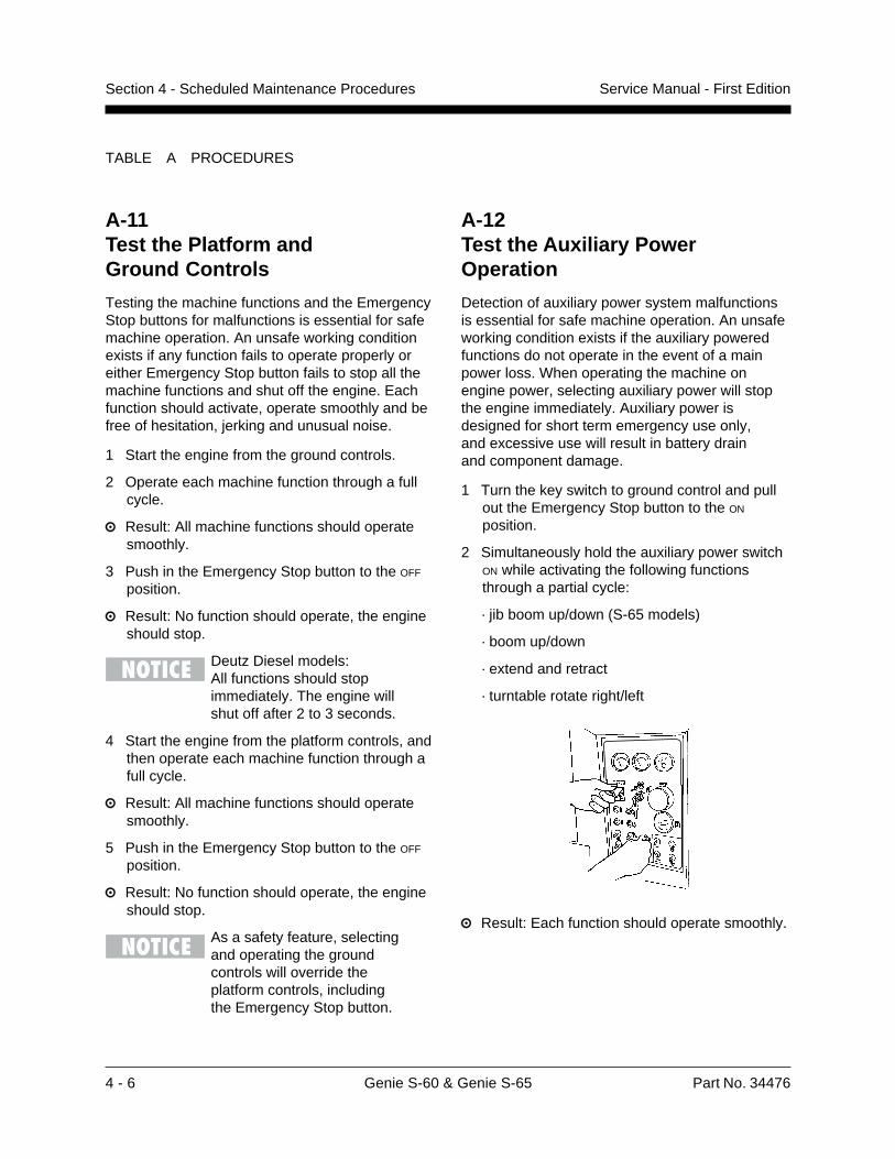
2 Simultaneously hold the auxiliary power switchON while activating the following functionsthrough a partial cycle:
· jib boom up/down (S-65 models)
· boom up/down
· extend and retract
· turntable rotate right/left
Result: Each function should operate smoothly.
A-11Test the Platform andGround Controls
Testing the machine functions and the EmergencyStop buttons for malfunctions is essential for safemachine operation. An unsafe working conditionexists if any function fails to operate properly oreither Emergency Stop button fails to stop all themachine functions and shut off the engine. Eachfunction should activate, operate smoothly and befree of hesitation, jerking and unusual noise.
1 Start the engine from the ground controls.
2 Operate each machine function through a fullcycle.
Result: All machine functions should operatesmoothly.
3 Push in the Emergency Stop button to the OFF
position.
Result: No function should operate, the engineshould stop.
Deutz Diesel models:All functions should stopimmediately. The engine willshut off after 2 to 3 seconds.
4 Start the engine from the platform controls, andthen operate each machine function through afull cycle.
Result: All machine functions should operatesmoothly.
5 Push in the Emergency Stop button to the OFF
position.
Result: No function should operate, the engineshould stop.
As a safety feature, selectingand operating the groundcontrols will override theplatform controls, includingthe Emergency Stop button.
Part No. 34476 Genie S-60 & Genie S-65 4 - 7
Service Manual - First Edition Section 4 - Scheduled Maintenance Procedures
TABLE A PROCEDURES
A-13Test the Tilt Sensor
The tilt sensor sounds an alarm in the platformwhen the incline of the turntable exceeds4.5 degrees.
Select a level test area. The tiltalarm should not be soundingprior to test.
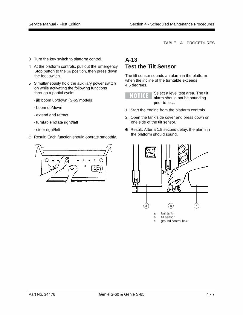
1 Start the engine from the platform controls.
2 Open the tank side cover and press down onone side of the tilt sensor.
Result: After a 1.5 second delay, the alarm inthe platform should sound.
a fuel tankb tilt sensorc ground control box
cba
3 Turn the key switch to platform control.
4 At the platform controls, pull out the EmergencyStop button to the ON position, then press downthe foot switch.
5 Simultaneously hold the auxiliary power switchon while activating the following functionsthrough a partial cycle:
· jib boom up/down (S-65 models)
· boom up/down
· extend and retract
· turntable rotate right/left
· steer right/left
Result: Each function should operate smoothly.
4 - 8 Genie S-60 & Genie S-65 Part No. 34476
Service Manual - First EditionSection 4 - Scheduled Maintenance Procedures
TABLE A PROCEDURES
3 Visually inspect the drive limit switch located onthe end of the cable track on the boom. Inspectfor the following:
· broken or missing roller or arm
· missing fasteners
· loose wiring
4 Start the engine from the platform controls.
5 Slowly move the drive control handleoff center.
Result: The machine should move at normaldrive speeds.
6 Raise the boom above the drive limit switch.
7 Slowly move the drive control handle off center.
Result: The machine should move at a reduceddrive speed.
8 Lower the boom to the stowed position, thenextend the boom 1 foot (30 cm).
9 Slowly move the drive control handle off center.
Result: The machine should move at a reduceddrive speed.
Drive speed, maximum, raised or extended
All models 1 foot per second0.31 meter per second
A-14Test the Limit SwitchesDrive Limit Switches
Detecting limit switch malfunctions is essential tosafe machine operation. The drive limit switchesare used to restrict drive speed when the boom israised or extended. An improperly functioningdrive limit switch will allow the machine to operatein an unsafe position.
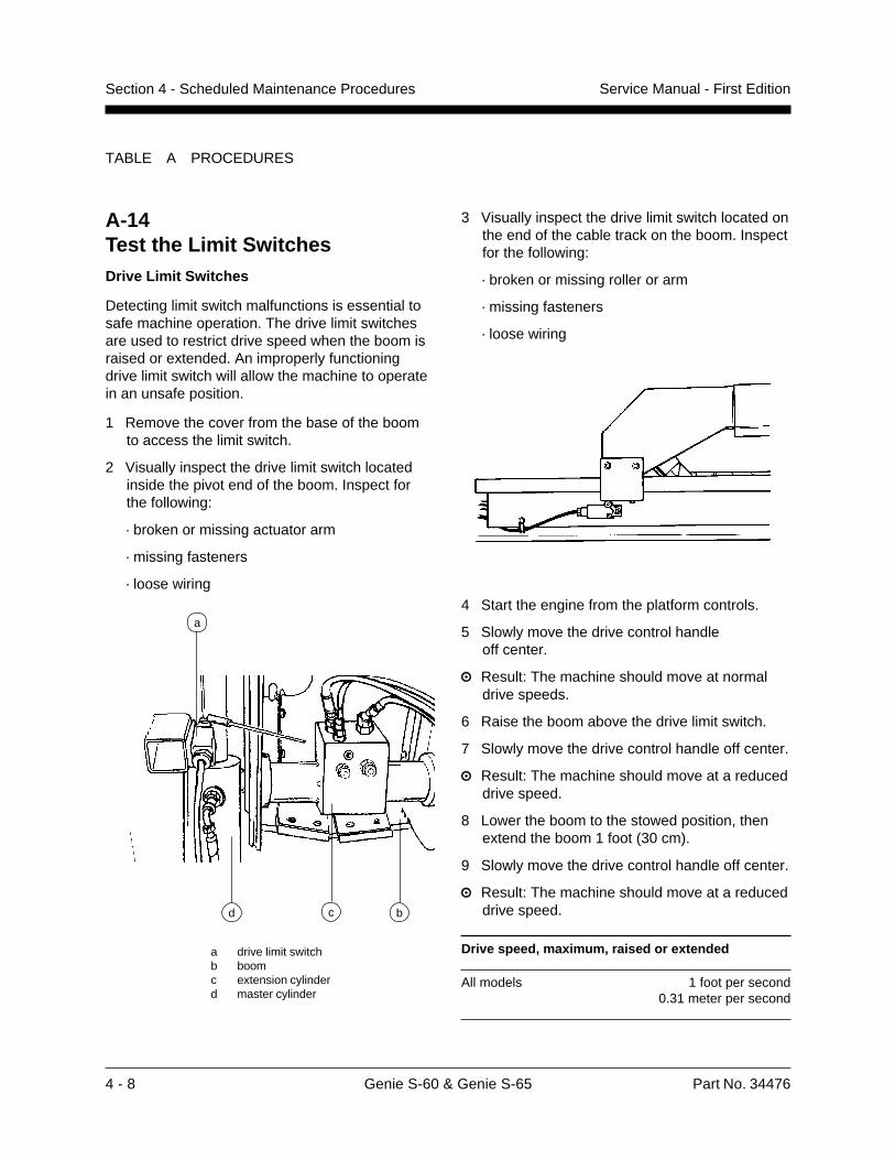
1 Remove the cover from the base of the boomto access the limit switch.
2 Visually inspect the drive limit switch locatedinside the pivot end of the boom. Inspect forthe following:
· broken or missing actuator arm
· missing fasteners
· loose wiring
a drive limit switchb boomc extension cylinderd master cylinder
a
d bc
Part No. 34476 Genie S-60 & Genie S-65 4 - 9
Service Manual - First Edition Section 4 - Scheduled Maintenance Procedures
TABLE A PROCEDURES
2 Manually activate the drive enable limit switch.
Result: The drive enable limit switch rollershould move freely and spring return to center.A distinct click should be felt and heard.
3 Start the engine from the platform controls.
4 Rotate the turntable to the left until the boom ispast the left non-steer wheel.
Result: The drive enable indicator light shouldbe on. Drive function should not operate untilthe drive enable switch is activated.
5 Rotate the turntable to the right until the boomis past the right non-steer wheel.
Result: The drive enable indicator light shouldbe on. Drive function should not operate untilthe drive enable switch is activated.
Drive Enable Limit Switch
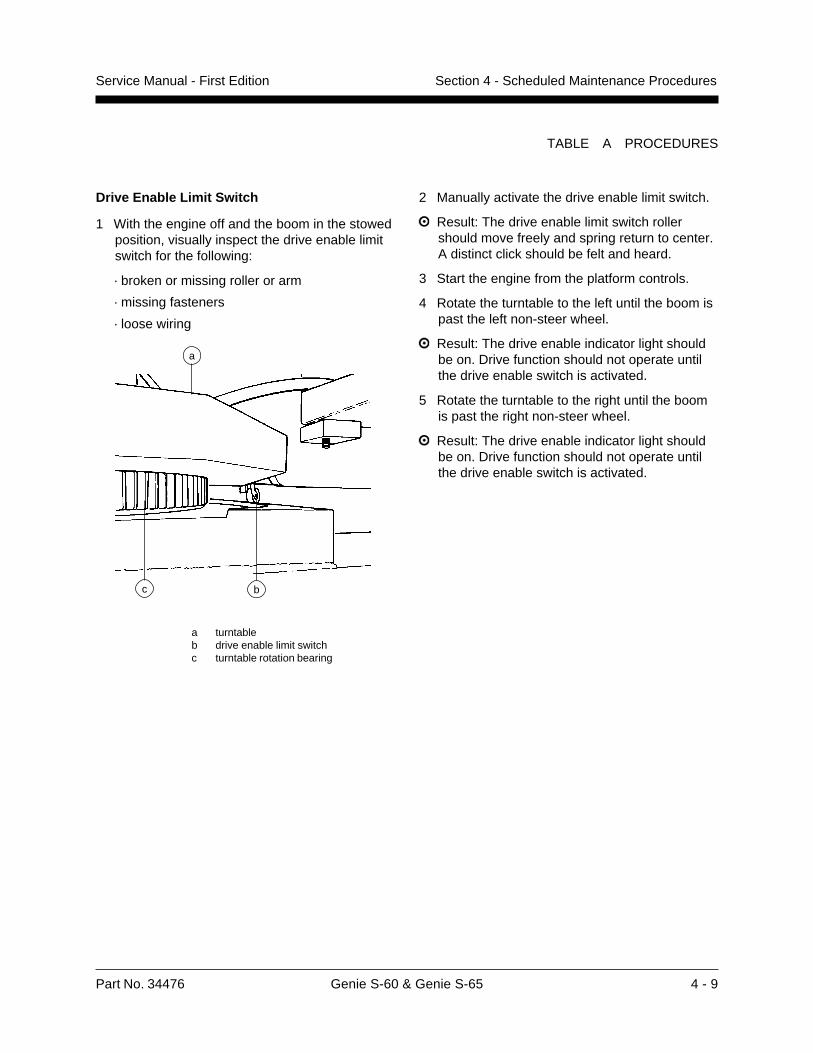
1 With the engine off and the boom in the stowedposition, visually inspect the drive enable limitswitch for the following:
· broken or missing roller or arm
· missing fasteners
· loose wiring
a turntableb drive enable limit switchc turntable rotation bearing
a
bc
4 - 10 Genie S-60 & Genie S-65 Part No. 34476
Service Manual - First EditionSection 4 - Scheduled Maintenance Procedures
TABLE A PROCEDURES
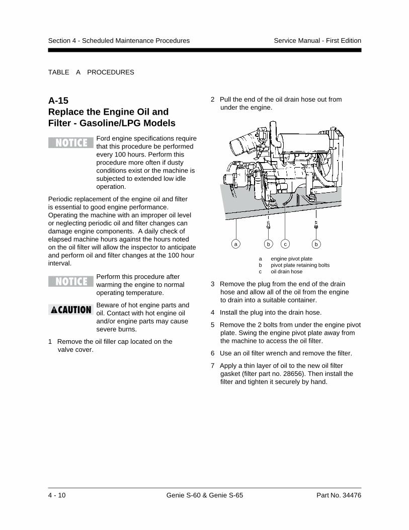
2 Pull the end of the oil drain hose out fromunder the engine.
a engine pivot plateb pivot plate retaining boltsc oil drain hose
3 Remove the plug from the end of the drainhose and allow all of the oil from the engineto drain into a suitable container.
4 Install the plug into the drain hose.
5 Remove the 2 bolts from under the engine pivotplate. Swing the engine pivot plate away fromthe machine to access the oil filter.
6 Use an oil filter wrench and remove the filter.
7 Apply a thin layer of oil to the new oil filtergasket (filter part no. 28656). Then install thefilter and tighten it securely by hand.
a b c b
A-15Replace the Engine Oil andFilter - Gasoline/LPG Models
Ford engine specifications requirethat this procedure be performedevery 100 hours. Perform thisprocedure more often if dustyconditions exist or the machine issubjected to extended low idleoperation.
Periodic replacement of the engine oil and filteris essential to good engine performance.Operating the machine with an improper oil levelor neglecting periodic oil and filter changes candamage engine components. A daily check ofelapsed machine hours against the hours notedon the oil filter will allow the inspector to anticipateand perform oil and filter changes at the 100 hourinterval.
Perform this procedure afterwarming the engine to normaloperating temperature.
Beware of hot engine parts andoil. Contact with hot engine oiland/or engine parts may causesevere burns.
1 Remove the oil filler cap located on thevalve cover.
Part No. 34476 Genie S-60 & Genie S-65 4 - 11
Service Manual - First Edition Section 4 - Scheduled Maintenance Procedures
TABLE A PROCEDURES
A-16Replace the Engine Air Filter
Engine specifications require thatthis procedure be performed every100 hours. Perform this proceduremore often if dusty conditionsexist.
Maintaining the engine air filter in good condition isessential to good engine performance and servicelife. Failure to perform this procedure can lead topoor engine performance and componentdamage.
Perform this procedure with theengine off.
1 Remove the end cap from the air cleanercanister.
2 Remove the mounting fastener from the airfilter, then remove the filter.
3 Clean the inside of the canister and the gasketwith a dry cloth.
4 Insert the new filter and replace the mountingfastener.
5 Replace the end cap on the canister.
Air filters - Genie part numbersFord LRG-423 Engine 27916Deutz F4L 1011 Engine 27916
8 Use a permanent ink marker to write the dateand number of hours from the hour meter onthe oil filter.
9 Fill the engine with new oil per specificationsand install the filler cap.
10 Start the engine from the ground controls.Allow the engine to run for 30 seconds, thenturn the engine off.
11 Check the oil filter and the oil drain hosefor leaks.
12 Swing the engine pivot plate back to its originalposition and replace the two retaining bolts.
13 Check the engine oil level dipstick. Add oilif needed.
Ford LRG-423 Engine 5 quartsOil capacity (including filter) 4.7 liters
Ford LRG-423 EngineOil viscosity requirements
below 60F / 15.5C 5W-30
-10 to 90F / -23 to 32C 10W-30
above -10F / -23C 10W-40 or 10W-50
above 25F / -4C 20W-40 or 20W-50
Use oils meeting API classification SF (labeled SF/CCor SF/CD) as they offer improved wear protection.
4 - 12 Genie S-60 & Genie S-65 Part No. 34476
Service Manual - First EditionSection 4 - Scheduled Maintenance Procedures
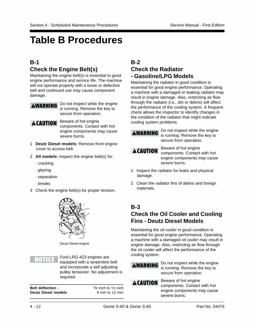
B-1Check the Engine Belt(s)Maintaining the engine belt(s) is essential to goodengine performance and service life. The machinewill not operate properly with a loose or defectivebelt and continued use may cause componentdamage.
Do not inspect while the engineis running. Remove the key tosecure from operation.
Beware of hot enginecomponents. Contact with hotengine components may causesevere burns.
1 Deutz Diesel models: Remove front enginecover to access belt.
2 All models: Inspect the engine belt(s) for:
· cracking
· glazing
· separation
· breaks
3 Check the engine belt(s) for proper tension.
Ford LRG-423 engines areequipped with a serpentine beltand incorporate a self adjustingpulley tensioner. No adjustment isrequired.
Belt deflection - 3/8 inch to 1/2 inchDeutz Diesel models 9 mm to 12 mm
Table B Procedures
Deutz Diesel engine
B-2Check the Radiator- Gasoline/LPG ModelsMaintaining the radiator in good condition isessential for good engine performance. Operatinga machine with a damaged or leaking radiator mayresult in engine damage. Also, restricting air flowthrough the radiator (i.e., dirt or debris) will affectthe performance of the cooling system. A frequentcheck allows the inspector to identify changes inthe condition of the radiator that might indicatecooling system problems.
Do not inspect while the engineis running. Remove the key tosecure from operation.
Beware of hot enginecomponents. Contact with hotengine components may causesevere burns.
1 Inspect the radiator for leaks and physicaldamage.
2 Clean the radiator fins of debris and foreignmaterials.
B-3Check the Oil Cooler and CoolingFins - Deutz Diesel ModelsMaintaining the oil cooler in good condition isessential for good engine performance. Operatinga machine with a damaged oil cooler may result inengine damage. Also, restricting air flow throughthe oil cooler will affect the performance of thecooling system.
Do not inspect while the engineis running. Remove the key tosecure from operation.
Beware of hot enginecomponents. Contact with hotengine components may causesevere burns.
Part No. 34476 Genie S-60 & Genie S-65 4 - 13
Service Manual - First Edition Section 4 - Scheduled Maintenance Procedures
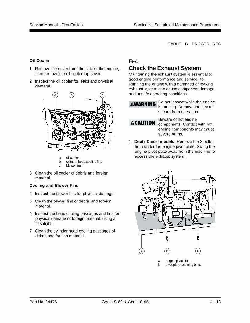
B-4Check the Exhaust SystemMaintaining the exhaust system is essential togood engine performance and service life.Running the engine with a damaged or leakingexhaust system can cause component damageand unsafe operating conditions.
Do not inspect while the engineis running. Remove the key tosecure from operation.
Beware of hot enginecomponents. Contact with hotengine components may causesevere burns.
1 Deutz Diesel models: Remove the 2 boltsfrom under the engine pivot plate. Swing theengine pivot plate away from the machine toaccess the exhaust system.
a engine pivot plateb pivot plate retaining bolts
TABLE B PROCEDURES
a bb
Oil Cooler
1 Remove the cover from the side of the engine,then remove the oil cooler top cover.
2 Inspect the oil cooler for leaks and physicaldamage.
a oil coolerb cylinder head cooling finsc blower fins
3 Clean the oil cooler of debris and foreignmaterial.
Cooling and Blower Fins
4 Inspect the blower fins for physical damage.
5 Clean the blower fins of debris and foreignmaterial.
6 Inspect the head cooling passages and fins forphysical damage or foreign material, using aflashlight.
7 Clean the cylinder head cooling passages ofdebris and foreign material.
a cb
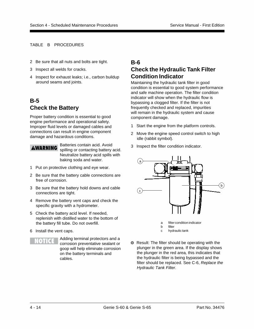
4 - 14 Genie S-60 & Genie S-65 Part No. 34476
Service Manual - First EditionSection 4 - Scheduled Maintenance Procedures
TABLE B PROCEDURES
B-5Check the BatteryProper battery condition is essential to goodengine performance and operational safety.Improper fluid levels or damaged cables andconnections can result in engine componentdamage and hazardous conditions.
Batteries contain acid. Avoidspilling or contacting battery acid.Neutralize battery acid spills withbaking soda and water.
1 Put on protective clothing and eye wear.
2 Be sure that the battery cable connections arefree of corrosion.
3 Be sure that the battery hold downs and cableconnections are tight.
4 Remove the battery vent caps and check thespecific gravity with a hydrometer.
5 Check the battery acid level. If needed,replenish with distilled water to the bottom ofthe battery fill tube. Do not overfill.
6 Install the vent caps.
Adding terminal protectors and acorrosion preventative sealant orgoop will help eliminate corrosionon the battery terminals andcables.
B-6Check the Hydraulic Tank FilterCondition IndicatorMaintaining the hydraulic tank filter in goodcondition is essential to good system performanceand safe machine operation. The filter conditionindicator will show when the hydraulic flow isbypassing a clogged filter. If the filter is notfrequently checked and replaced, impuritieswill remain in the hydraulic system and causecomponent damage.
1 Start the engine from the platform controls.
2 Move the engine speed control switch to highidle (rabbit symbol).
3 Inspect the filter condition indicator.
a filter condition indicatorb filterc hydraulic tank
Result: The filter should be operating with theplunger in the green area. If the display showsthe plunger in the red area, this indicates thatthe hydraulic filter is being bypassed and thefilter should be replaced. See C-6, Replace theHydraulic Tank Filter.
2 Be sure that all nuts and bolts are tight.
3 Inspect all welds for cracks.
4 Inspect for exhaust leaks; i.e., carbon builduparound seams and joints.
a
b
c
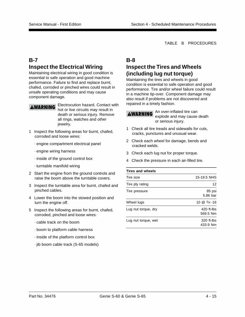
Part No. 34476 Genie S-60 & Genie S-65 4 - 15
Service Manual - First Edition Section 4 - Scheduled Maintenance Procedures
TABLE B PROCEDURES
B-8Inspect the Tires and Wheels(including lug nut torque)Maintaining the tires and wheels in goodcondition is essential to safe operation and goodperformance. Tire and/or wheel failure could resultin a machine tip-over. Component damage mayalso result if problems are not discovered andrepaired in a timely fashion.
An over-inflated tire canexplode and may cause deathor serious injury.
1 Check all tire treads and sidewalls for cuts,cracks, punctures and unusual wear.
2 Check each wheel for damage, bends andcracked welds.
3 Check each lug nut for proper torque.
4 Check the pressure in each air-filled tire.
Tires and wheels
Tire size 15-19.5 NHS
Tire ply rating 12
Tire pressure 85 psi5.86 bar
Wheel lugs 10 @ 3/4 -16
Lug nut torque, dry 420 ft-lbs569.5 Nm
Lug nut torque, wet 320 ft-lbs433.9 Nm
B-7Inspect the Electrical WiringMaintaining electrical wiring in good condition isessential to safe operation and good machineperformance. Failure to find and replace burnt,chafed, corroded or pinched wires could result inunsafe operating conditions and may causecomponent damage.
Electrocution hazard. Contact withhot or live circuits may result indeath or serious injury. Removeall rings, watches and otherjewelry.
1 Inspect the following areas for burnt, chafed,corroded and loose wires:
· engine compartment electrical panel
· engine wiring harness
· inside of the ground control box
· turntable manifold wiring
2 Start the engine from the ground controls andraise the boom above the turntable covers.
3 Inspect the turntable area for burnt, chafed andpinched cables.
4 Lower the boom into the stowed position andturn the engine off.
5 Inspect the following areas for burnt, chafed,corroded, pinched and loose wires:
· cable track on the boom
· boom to platform cable harness
· inside of the platform control box
· jib boom cable track (S-65 models)
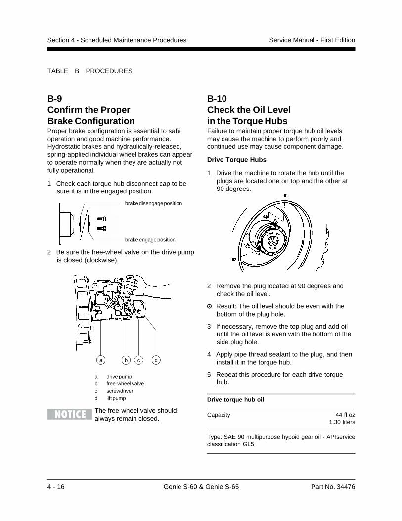
4 - 16 Genie S-60 & Genie S-65 Part No. 34476
Service Manual - First EditionSection 4 - Scheduled Maintenance Procedures
B-9Confirm the ProperBrake ConfigurationProper brake configuration is essential to safeoperation and good machine performance.Hydrostatic brakes and hydraulically-released,spring-applied individual wheel brakes can appearto operate normally when they are actually notfully operational.
1 Check each torque hub disconnect cap to besure it is in the engaged position.
2 Be sure the free-wheel valve on the drive pumpis closed (clockwise).
a drive pumpb free-wheel valvec screwdriverd lift pump
The free-wheel valve shouldalways remain closed.
TABLE B PROCEDURES
B-10Check the Oil Levelin the Torque HubsFailure to maintain proper torque hub oil levelsmay cause the machine to perform poorly andcontinued use may cause component damage.
Drive Torque Hubs
1 Drive the machine to rotate the hub until theplugs are located one on top and the other at90 degrees.
2 Remove the plug located at 90 degrees andcheck the oil level.
Result: The oil level should be even with thebottom of the plug hole.
3 If necessary, remove the top plug and add oiluntil the oil level is even with the bottom of theside plug hole.
4 Apply pipe thread sealant to the plug, and theninstall it in the torque hub.
5 Repeat this procedure for each drive torquehub.
Drive torque hub oil
Capacity 44 fl oz1.30 liters
Type: SAE 90 multipurpose hypoid gear oil - APIserviceclassification GL5
brake disengage position
brake engage position
b ca d
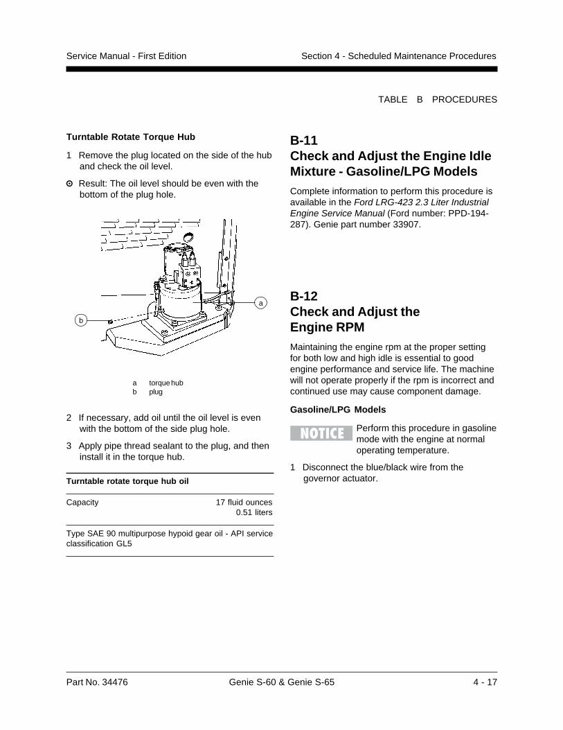
Part No. 34476 Genie S-60 & Genie S-65 4 - 17
Service Manual - First Edition Section 4 - Scheduled Maintenance Procedures
Turntable Rotate Torque Hub
1 Remove the plug located on the side of the huband check the oil level.
Result: The oil level should be even with thebottom of the plug hole.
a torque hubb plug
2 If necessary, add oil until the oil level is evenwith the bottom of the side plug hole.
3 Apply pipe thread sealant to the plug, and theninstall it in the torque hub.
Turntable rotate torque hub oil
Capacity 17 fluid ounces0.51 liters
Type SAE 90 multipurpose hypoid gear oil - API serviceclassification GL5
TABLE B PROCEDURES
B-11Check and Adjust the Engine IdleMixture - Gasoline/LPG ModelsComplete information to perform this procedure isavailable in the Ford LRG-423 2.3 Liter IndustrialEngine Service Manual (Ford number: PPD-194-287). Genie part number 33907.
b
aB-12Check and Adjust theEngine RPMMaintaining the engine rpm at the proper settingfor both low and high idle is essential to goodengine performance and service life. The machinewill not operate properly if the rpm is incorrect andcontinued use may cause component damage.
Gasoline/LPG Models
Perform this procedure in gasolinemode with the engine at normaloperating temperature.
1 Disconnect the blue/black wire from thegovernor actuator.
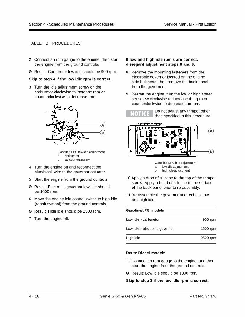
4 - 18 Genie S-60 & Genie S-65 Part No. 34476
Service Manual - First EditionSection 4 - Scheduled Maintenance Procedures
TABLE B PROCEDURES
2 Connect an rpm gauge to the engine, then startthe engine from the ground controls.
Result: Carburetor low idle should be 900 rpm.
Skip to step 4 if the low idle rpm is correct.
3 Turn the idle adjustment screw on thecarburetor clockwise to increase rpm orcounterclockwise to decrease rpm.
Gasoline/LPG low idle adjustmenta carburetorb adjustment screw
4 Turn the engine off and reconnect theblue/black wire to the governor actuator.
5 Start the engine from the ground controls.
Result: Electronic governor low idle shouldbe 1600 rpm.
6 Move the engine idle control switch to high idle(rabbit symbol) from the ground controls.
Result: High idle should be 2500 rpm.
7 Turn the engine off.
b
a
If low and high idle rpm’s are correct,disregard adjustment steps 8 and 9.
8 Remove the mounting fasteners from theelectronic governor located on the engineside bulkhead, then remove the back panelfrom the governor.
9 Restart the engine, turn the low or high speedset screw clockwise to increase the rpm orcounterclockwise to decrease the rpm.
Do not adjust any trimpot otherthan specified in this procedure.
Gasoline/LPG idle adjustmenta low idle adjustmentb high idle adjustment
10 Apply a drop of silicone to the top of the trimpotscrew. Apply a bead of silicone to the surfaceof the back panel prior to re-assembly.
11 Re-assemble the governor and recheck lowand high idle.
Gasoline/LPG models
Low idle - carburetor 900 rpm
Low idle - electronic governor 1600 rpm
High idle 2500 rpm
Deutz Diesel models
1 Connect an rpm gauge to the engine, and thenstart the engine from the ground controls.
Result: Low idle should be 1300 rpm.
Skip to step 3 if the low idle rpm is correct.
b
a
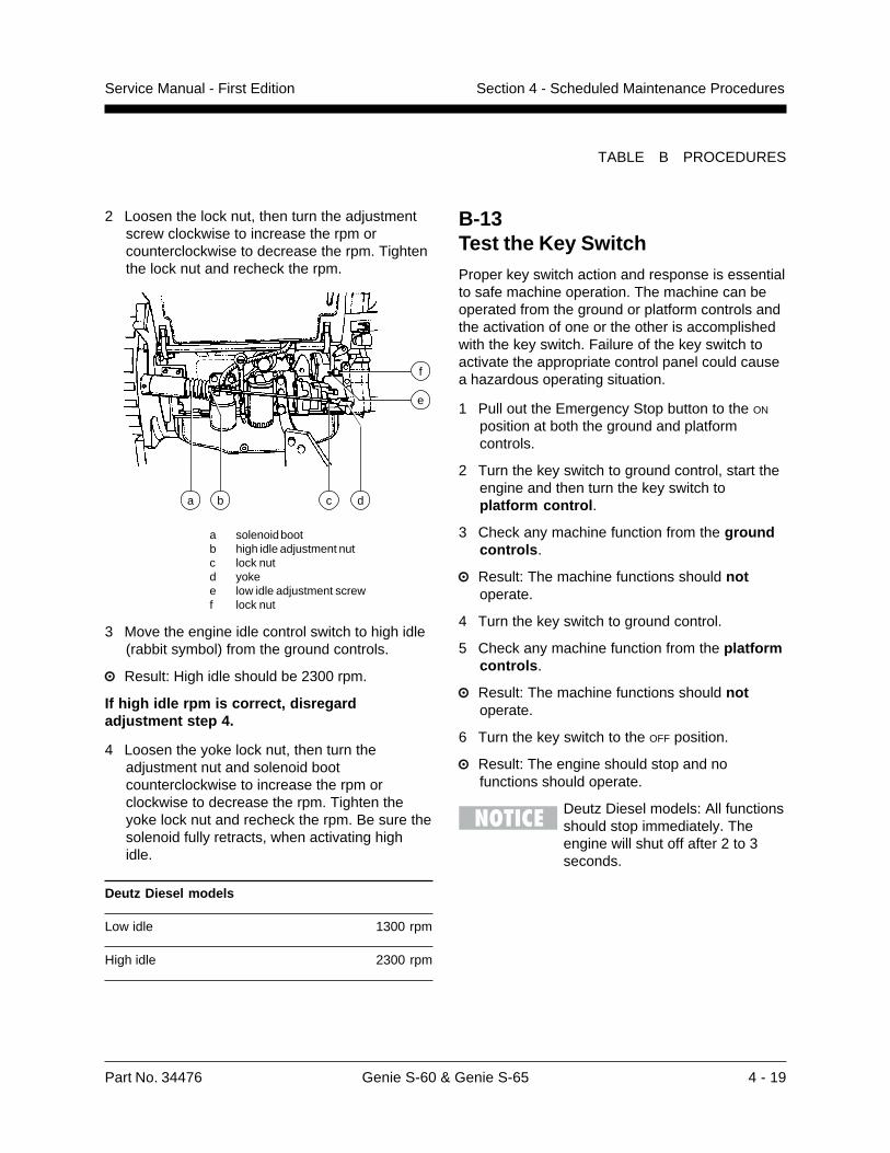
Part No. 34476 Genie S-60 & Genie S-65 4 - 19
Service Manual - First Edition Section 4 - Scheduled Maintenance Procedures
TABLE B PROCEDURES
2 Loosen the lock nut, then turn the adjustmentscrew clockwise to increase the rpm orcounterclockwise to decrease the rpm. Tightenthe lock nut and recheck the rpm.
a solenoid bootb high idle adjustment nutc lock nutd yokee low idle adjustment screwf lock nut
3 Move the engine idle control switch to high idle(rabbit symbol) from the ground controls.
Result: High idle should be 2300 rpm.
If high idle rpm is correct, disregardadjustment step 4.
4 Loosen the yoke lock nut, then turn theadjustment nut and solenoid bootcounterclockwise to increase the rpm orclockwise to decrease the rpm. Tighten theyoke lock nut and recheck the rpm. Be sure thesolenoid fully retracts, when activating highidle.
Deutz Diesel models
Low idle 1300 rpm
High idle 2300 rpm
f
e
c dba
B-13Test the Key SwitchProper key switch action and response is essentialto safe machine operation. The machine can beoperated from the ground or platform controls andthe activation of one or the other is accomplishedwith the key switch. Failure of the key switch toactivate the appropriate control panel could causea hazardous operating situation.
1 Pull out the Emergency Stop button to the ON
position at both the ground and platformcontrols.
2 Turn the key switch to ground control, start theengine and then turn the key switch toplatform control.
3 Check any machine function from the groundcontrols.
Result: The machine functions should notoperate.
4 Turn the key switch to ground control.
5 Check any machine function from the platformcontrols.
Result: The machine functions should notoperate.
6 Turn the key switch to the OFF position.
Result: The engine should stop and nofunctions should operate.
Deutz Diesel models: All functionsshould stop immediately. Theengine will shut off after 2 to 3seconds.
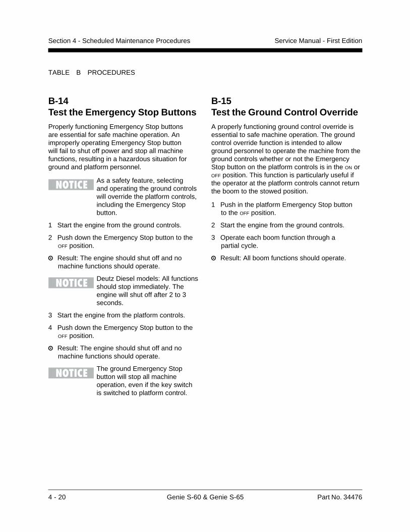
4 - 20 Genie S-60 & Genie S-65 Part No. 34476
Service Manual - First EditionSection 4 - Scheduled Maintenance Procedures
TABLE B PROCEDURES
B-14Test the Emergency Stop ButtonsProperly functioning Emergency Stop buttonsare essential for safe machine operation. Animproperly operating Emergency Stop buttonwill fail to shut off power and stop all machinefunctions, resulting in a hazardous situation forground and platform personnel.
As a safety feature, selectingand operating the ground controlswill override the platform controls,including the Emergency Stopbutton.
1 Start the engine from the ground controls.
2 Push down the Emergency Stop button to theOFF position.
Result: The engine should shut off and nomachine functions should operate.
Deutz Diesel models: All functionsshould stop immediately. Theengine will shut off after 2 to 3seconds.
3 Start the engine from the platform controls.
4 Push down the Emergency Stop button to theOFF position.
Result: The engine should shut off and nomachine functions should operate.
The ground Emergency Stopbutton will stop all machineoperation, even if the key switchis switched to platform control.
B-15Test the Ground Control OverrideA properly functioning ground control override isessential to safe machine operation. The groundcontrol override function is intended to allowground personnel to operate the machine from theground controls whether or not the EmergencyStop button on the platform controls is in the ON orOFF position. This function is particularly useful ifthe operator at the platform controls cannot returnthe boom to the stowed position.
1 Push in the platform Emergency Stop buttonto the OFF position.
2 Start the engine from the ground controls.
3 Operate each boom function through apartial cycle.
Result: All boom functions should operate.
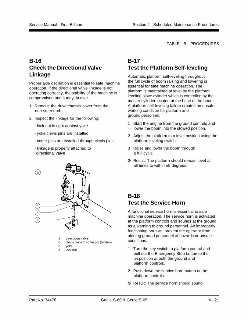
Part No. 34476 Genie S-60 & Genie S-65 4 - 21
Service Manual - First Edition Section 4 - Scheduled Maintenance Procedures
TABLE B PROCEDURES
B-18Test the Service HornA functional service horn is essential to safemachine operation. The service horn is activatedat the platform controls and sounds at the groundas a warning to ground personnel. An improperlyfunctioning horn will prevent the operator fromalerting ground personnel of hazards or unsafeconditions.
1 Turn the key switch to platform control andpull out the Emergency Stop button to theON position at both the ground andplatform controls.
2 Push down the service horn button at theplatform controls.
Result: The service horn should sound.
B-17Test the Platform Self-levelingAutomatic platform self-leveling throughoutthe full cycle of boom raising and lowering isessential for safe machine operation. Theplatform is maintained at level by the platformleveling slave cylinder which is controlled by themaster cylinder located at the base of the boom.A platform self-leveling failure creates an unsafeworking condition for platform andground personnel.
1 Start the engine from the ground controls andlower the boom into the stowed position.
2 Adjust the platform to a level position using theplatform leveling switch.
3 Raise and lower the boom througha full cycle.
Result: The platform should remain level atall times to within ±5 degrees.
B-16Check the Directional ValveLinkageProper axle oscillation is essential to safe machineoperation. If the directional valve linkage is notoperating correctly, the stability of the machine iscompromised and it may tip over.
1 Remove the drive chassis cover from thenon-steer end.
2 Inspect the linkage for the following:
· lock nut is tight against yoke
· yoke clevis pins are installed
· cotter pins are installed through clevis pins
· linkage is properly attached to directional valve
a
b
c
d
a directional valveb clevis pin with cotter pin (hidden)c yoked lock nut

4 - 22 Genie S-60 & Genie S-65 Part No. 34476
Service Manual - First EditionSection 4 - Scheduled Maintenance Procedures
TABLE B PROCEDURES
Foot switch activated high idle (rabbit and footswitch symbols) should be used for normalmachine operation. This selection activates highidle only when the foot switch is pressed down.
1 Pull out the Emergency Stop button to theON position at both the ground and platformcontrols.
2 Start the engine from the ground controls. Thenmove the engine idle control switch to high idle(rabbit symbol) and hold in the ON position.
Result: The engine should change to high idle.
3 Release the engine idle control switch.
Result: The engine should return to low idle.
4 Turn the key switch to platform controls.
5 At the platform controls, move the engine idlecontrol switch to high idle (rabbit symbol).
Result: The engine should change to high idle.
6 Move the engine idle control switch to low idle(turtle symbol).
Result: The engine should change to low idle.
7 Move the engine idle control switch to footswitch activated high idle (rabbit and footswitch symbol).
Result: The engine should not change tohigh idle.
8 Press down the foot switch.
Result: The engine should change to high idle.
Gasoline/LPG models
Low idle 1600 rpm
High idle 2500 rpm
Deutz Diesel models
Low idle 1300 rpm
High idle 2300 rpm
B-19Test the Foot SwitchA properly functioning foot switch is essential tosafe machine operation. Machine functions shouldactivate and operate smoothly as long as the footswitch is pressed down, and promptly stop whenthe foot switch is released. The foot switch willalso shift the engine into high idle if the idle selectis switched to the rabbit and foot switch symbol.An improperly functioning foot switch can causean unsafe working condition and endangerplatform and ground personnel.
The engine should not start if thefoot switch is pressed down.
1 Start the engine from the platform controls.
2 Without pressing down the foot switch, checkthe machine functions.
Result: The machine functions should notoperate.
3 Press down the foot switch and operate themachine functions.
Result: The machine functions should operate.
B-20Test the Engine Idle SelectA properly operating engine idle select switchis essential to good engine performance and safemachine operation. There are three settings.
Low idle (turtle symbol) allows the operator tocontrol individual boom functions only. Drivefunctions do not operate at low idle.
High idle (rabbit symbol) allows the operatorto control multiple boom and/or drive functionssimultaneously. This setting maintains aconsistent high idle and is usually selected onlywhen the generator option is being used.
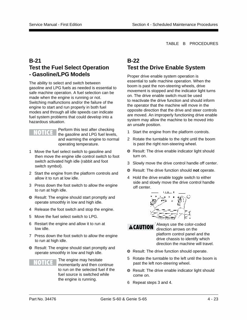
Part No. 34476 Genie S-60 & Genie S-65 4 - 23
Service Manual - First Edition Section 4 - Scheduled Maintenance Procedures
TABLE B PROCEDURES
B-22Test the Drive Enable SystemProper drive enable system operation isessential to safe machine operation. When theboom is past the non-steering wheels, drivemovement is stopped and the indicator light turnson. The drive enable switch must be usedto reactivate the drive function and should informthe operator that the machine will move in theopposite direction that the drive and steer controlsare moved. An improperly functioning drive enablesystem may allow the machine to be moved intoan unsafe position.
1 Start the engine from the platform controls.
2 Rotate the turntable to the right until the boomis past the right non-steering wheel.
Result: The drive enable indicator light shouldturn on.
3 Slowly move the drive control handle off center.
Result: The drive function should not operate.
4 Hold the drive enable toggle switch to eitherside and slowly move the drive control handleoff center.
`Always use the color-codeddirection arrows on theplatform control panel and thedrive chassis to identify whichdirection the machine will travel.
Result: The drive function should operate.
5 Rotate the turntable to the left until the boom ispast the left non-steering wheel.
Result: The drive enable indicator light shouldcome on.
6 Repeat steps 3 and 4.
B-21Test the Fuel Select Operation- Gasoline/LPG ModelsThe ability to select and switch betweengasoline and LPG fuels as needed is essential tosafe machine operation. A fuel selection can bemade when the engine is running or not.Switching malfunctions and/or the failure of theengine to start and run properly in both fuelmodes and through all idle speeds can indicatefuel system problems that could develop into ahazardous situation.
Perform this test after checkingthe gasoline and LPG fuel levels,and warming the engine to normaloperating temperature.
1 Move the fuel select switch to gasoline andthen move the engine idle control switch to footswitch activated high idle (rabbit and footswitch symbol).
2 Start the engine from the platform controls andallow it to run at low idle.
3 Press down the foot switch to allow the engineto run at high idle.
Result: The engine should start promptly andoperate smoothly in low and high idle.
4 Release the foot switch and stop the engine.
5 Move the fuel select switch to LPG.
6 Restart the engine and allow it to run atlow idle.
7 Press down the foot switch to allow the engineto run at high idle.
Result: The engine should start promptly andoperate smoothly in low and high idle.
The engine may hesitatemomentarily and then continueto run on the selected fuel if thefuel source is switched whilethe engine is running.
4 - 24 Genie S-60 & Genie S-65 Part No. 34476
Service Manual - First EditionSection 4 - Scheduled Maintenance Procedures
TABLE B PROCEDURES
B-24Test the Drive Speed- Stowed PositionProper drive function movement is essential tosafe machine operation. The drive function shouldrespond quickly and smoothly to operator control.Drive performance should also be free ofhesitation, jerking and unusual noise over theentire proportionally controlled speed range.
Select a test area that is firm,level and free of obstructions.
1 Create start and finish lines by marking twolines on the ground 40 feet (12.2 m) apart.
2 Start the engine from the platform controls.
3 Move the engine idle control switch tofoot switch activated high idle (rabbit and footswitch), then lower the boom into the stowedposition.
4 Choose a point on the machine; i.e., contactpatch of a tire, as a visual reference for usewhen crossing the start and finish lines.
5 Bring the machine to top drive speed beforereaching the start line. Begin timing when yourreference point on the machine crosses thestart line.
6 Continue at full speed and note the time whenthe machine reference point crosses the finishline.
Drive speed:stowed position 2WD 4WD
Gasoline/LPG models 40 ft/6.2 sec 40 ft/9.1 sec12.2 m/6.2 sec 12.2 m/9.1 sec
Deutz Diesel models 40 ft/6.8 sec 40 ft/9.1 sec12.2 m/6.8 sec 12.2 m/9.1 sec
B-23Test the Drive BrakesProper brake action is essential to safe machineoperation. The drive brake function should operatesmoothly, free of hesitation, jerking and unusualnoise. Hydrostatic brakes and hydraulically-released individual wheel brakes can appear tooperate normally when they are actually not fullyoperational.
Be sure that the machine is not infree-wheel or partial free-wheelconfiguration. Refer to B-9 in thissection, Confirm the Proper BrakeConfiguration.
Select a test area that is firm,level and free of obstructions.
1 Mark a test line on the ground for reference.
2 Start the engine from the platform controls.
3 Move the engine idle control switch tofoot switch activated high idle (rabbit andfoot switch), then lower the boom into thestowed position.
4 Choose a point on the machine; i.e., contactpatch of a tire, as a visual reference for usewhen crossing the test line.
5 Bring the machine to top drive speed beforereaching the test line. Release the drivejoystick when your reference point on themachine crosses the test line.
6 Measure the distance between the test line andyour machine reference point.
Braking:paved surface 2WD 4WD
Stopping distance 3 to 5 ft 5 to 7 ft0.91 to 1.5 m 1.5 to 2.1 m
The brakes must be able to holdthe machine on any slope it isable to climb.
Part No. 34476 Genie S-60 & Genie S-65 4 - 25
Service Manual - First Edition Section 4 - Scheduled Maintenance Procedures
TABLE B PROCEDURES
B-25Test the Alarm Package- Optional EquipmentThe alarm package includes:
· travel alarm
· descent alarm
· flashing beacon
Alarms and a beacon are installed to alertoperators and ground personnel of machineproximity and motion. The alarm package isinstalled on the turntable covers.
The alarms and beacon willoperate with the enginerunning or not running.
1 At the ground controls, pull out the EmergencyStop button to the ON position and turn the keyswitch to ground control.
Result: The flashing beacon should be on andflashing.
2 Move the boom switch to the DOWN position,hold for a moment and then release it.
Result: The descent alarm should sound whenthe switch is held down.
3 Turn the key switch to platform control.
4 At the platform controls pull out the EmergencyStop button to the ON position.
Result: The flashing beacon should be onand flashing.
5 Press down the foot switch. Move the boomcontrol handle to the DOWN position, hold for amoment and then release it.
Result: The descent alarm should sound whenthe control handle is held down.
6 Press down the foot switch. Move the drivecontrol handle off center, hold for a momentand then release it. Move the drive controlhandle off center in the opposite direction, holdfor a moment and then release it.
Result: The travel alarm should sound whenthe drive control handle is moved off center ineither direction.
B-26Perform Hydraulic Oil AnalysisSee D-1, Test or Replace the Hydraulic Oil.
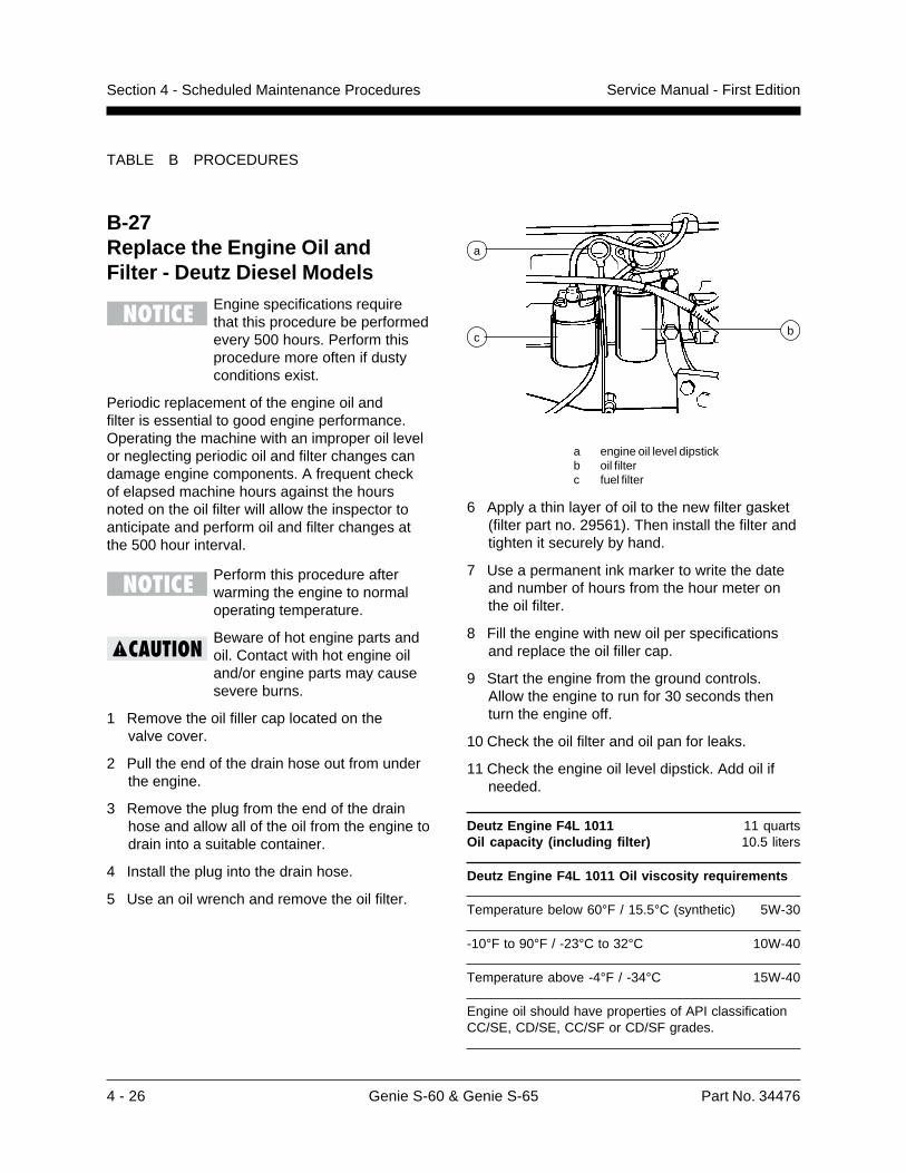
4 - 26 Genie S-60 & Genie S-65 Part No. 34476
Service Manual - First EditionSection 4 - Scheduled Maintenance Procedures
TABLE B PROCEDURES
a engine oil level dipstickb oil filterc fuel filter
6 Apply a thin layer of oil to the new filter gasket(filter part no. 29561). Then install the filter andtighten it securely by hand.
7 Use a permanent ink marker to write the dateand number of hours from the hour meter onthe oil filter.
8 Fill the engine with new oil per specificationsand replace the oil filler cap.
9 Start the engine from the ground controls.Allow the engine to run for 30 seconds thenturn the engine off.
10 Check the oil filter and oil pan for leaks.
11 Check the engine oil level dipstick. Add oil ifneeded.
Deutz Engine F4L 1011 11 quartsOil capacity (including filter) 10.5 liters
Deutz Engine F4L 1011 Oil viscosity requirements
Temperature below 60°F / 15.5°C (synthetic) 5W-30
-10°F to 90°F / -23°C to 32°C 10W-40
Temperature above -4°F / -34°C 15W-40
Engine oil should have properties of API classificationCC/SE, CD/SE, CC/SF or CD/SF grades.
a
bc
B-27Replace the Engine Oil andFilter - Deutz Diesel Models
Engine specifications requirethat this procedure be performedevery 500 hours. Perform thisprocedure more often if dustyconditions exist.
Periodic replacement of the engine oil andfilter is essential to good engine performance.Operating the machine with an improper oil levelor neglecting periodic oil and filter changes candamage engine components. A frequent checkof elapsed machine hours against the hoursnoted on the oil filter will allow the inspector toanticipate and perform oil and filter changes atthe 500 hour interval.
Perform this procedure afterwarming the engine to normaloperating temperature.
Beware of hot engine parts andoil. Contact with hot engine oiland/or engine parts may causesevere burns.
1 Remove the oil filler cap located on thevalve cover.
2 Pull the end of the drain hose out from underthe engine.
3 Remove the plug from the end of the drainhose and allow all of the oil from the engine todrain into a suitable container.
4 Install the plug into the drain hose.
5 Use an oil wrench and remove the oil filter.
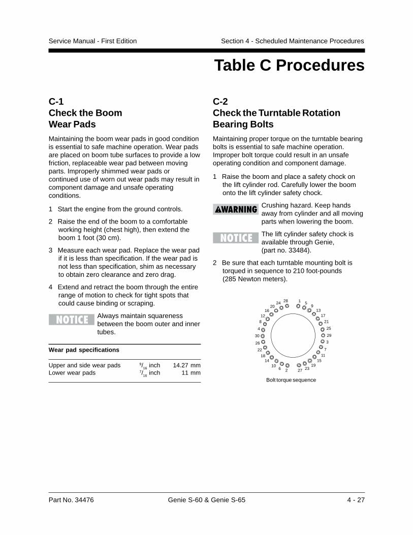
Part No. 34476 Genie S-60 & Genie S-65 4 - 27
Service Manual - First Edition Section 4 - Scheduled Maintenance Procedures
C-1Check the BoomWear PadsMaintaining the boom wear pads in good conditionis essential to safe machine operation. Wear padsare placed on boom tube surfaces to provide a lowfriction, replaceable wear pad between movingparts. Improperly shimmed wear pads orcontinued use of worn out wear pads may result incomponent damage and unsafe operatingconditions.
1 Start the engine from the ground controls.
2 Raise the end of the boom to a comfortableworking height (chest high), then extend theboom 1 foot (30 cm).
3 Measure each wear pad. Replace the wear padif it is less than specification. If the wear pad isnot less than specification, shim as necessaryto obtain zero clearance and zero drag.
4 Extend and retract the boom through the entirerange of motion to check for tight spots thatcould cause binding or scraping.
Always maintain squarenessbetween the boom outer and innertubes.
Wear pad specifications
Upper and side wear pads 9/16 inch 14.27 mmLower wear pads 7/16 inch 11 mm
Table C Procedures
C-2Check the Turntable RotationBearing BoltsMaintaining proper torque on the turntable bearingbolts is essential to safe machine operation.Improper bolt torque could result in an unsafeoperating condition and component damage.
1 Raise the boom and place a safety chock onthe lift cylinder rod. Carefully lower the boomonto the lift cylinder safety chock.
Crushing hazard. Keep handsaway from cylinder and all movingparts when lowering the boom.
The lift cylinder safety chock isavailable through Genie,(part no. 33484).
2 Be sure that each turntable mounting bolt istorqued in sequence to 210 foot-pounds(285 Newton meters).
Bolt torque sequence
1
2
3
4
5
6
7
8
9
10
11
1213
14 15
1617
18
22
26
30
192327
2024 28
21
25
29
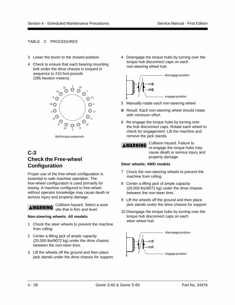
4 - 28 Genie S-60 & Genie S-65 Part No. 34476
Service Manual - First EditionSection 4 - Scheduled Maintenance Procedures
TABLE C PROCEDURES
3 Lower the boom to the stowed position.
4 Check to ensure that each bearing mountingbolt under the drive chassis is torqued insequence to 210 foot-pounds(285 Newton meters).
4 Disengage the torque hubs by turning over thetorque hub disconnect caps on eachnon-steering wheel hub.
5 Manually rotate each non-steering wheel.
Result: Each non-steering wheel should rotatewith minimum effort.
6 Re-engage the torque hubs by turning overthe hub disconnect caps. Rotate each wheel tocheck for engagement. Lift the machine andremove the jack stands.
Collision hazard. Failure tore-engage the torque hubs maycause death or serious injury andproperty damage.
Steer wheels: 4WD models
7 Chock the non-steering wheels to prevent themachine from rolling.
8 Center a lifting jack of ample capacity(20,000 lbs/9072 kg) under the drive chassisbetween the non-steer tires.
9 Lift the wheels off the ground and then placejack stands under the drive chassis for support.
10 Disengage the torque hubs by turning over thetorque hub disconnect caps on eachsteer wheel hub.
Bolt torque sequence
1 15
7
12
4
17
5
14
9216
8
11
3
18
6
13
10
C-3Check the Free-wheelConfigurationProper use of the free-wheel configuration isessential to safe machine operation. Thefree-wheel configuration is used primarily fortowing. A machine configured to free-wheelwithout operator knowledge may cause death orserious injury and property damage.
Collision hazard. Select a worksite that is firm and level.
Non-steering wheels: All models
1 Chock the steer wheels to prevent the machinefrom rolling.
2 Center a lifting jack of ample capacity(20,000 lbs/9072 kg) under the drive chassisbetween the non-steer tires.
3 Lift the wheels off the ground and then placejack stands under the drive chassis for support.
disengage position
engage position
disengage position
engage position
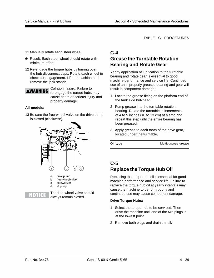
Part No. 34476 Genie S-60 & Genie S-65 4 - 29
Service Manual - First Edition Section 4 - Scheduled Maintenance Procedures
TABLE C PROCEDURES
C-4Grease the Turntable RotationBearing and Rotate GearYearly application of lubrication to the turntablebearing and rotate gear is essential to goodmachine performance and service life. Continueduse of an improperly greased bearing and gear willresult in component damage.
1 Locate the grease fitting on the platform end ofthe tank side bulkhead.
2 Pump grease into the turntable rotationbearing. Rotate the turntable in incrementsof 4 to 5 inches (10 to 13 cm) at a time andrepeat this step until the entire bearing hasbeen greased.
3 Apply grease to each tooth of the drive gear,located under the turntable.
Oil type Multipurpose grease
C-5Replace the Torque Hub OilReplacing the torque hub oil is essential for goodmachine performance and service life. Failure toreplace the torque hub oil at yearly intervals maycause the machine to perform poorly andcontinued use may cause component damage.
Drive Torque Hubs:
1 Select the torque hub to be serviced. Thendrive the machine until one of the two plugs isat the lowest point.
2 Remove both plugs and drain the oil.
11 Manually rotate each steer wheel.
Result: Each steer wheel should rotate withminimum effort.
12 Re-engage the torque hubs by turning overthe hub disconnect caps. Rotate each wheel tocheck for engagement. Lift the machine andremove the jack stands.
Collision hazard. Failure tore-engage the torque hubs maycause death or serious injury andproperty damage.
All models:
13 Be sure the free-wheel valve on the drive pumpis closed (clockwise).
a drive pumpb free-wheel valvec screwdriverd lift pump
The free-wheel valve shouldalways remain closed.
a b dc
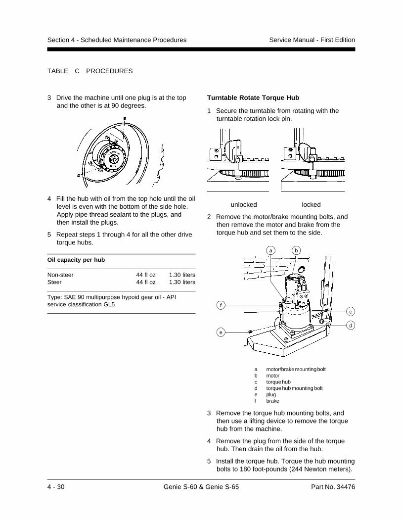
4 - 30 Genie S-60 & Genie S-65 Part No. 34476
Service Manual - First EditionSection 4 - Scheduled Maintenance Procedures
3 Drive the machine until one plug is at the topand the other is at 90 degrees.
4 Fill the hub with oil from the top hole until the oillevel is even with the bottom of the side hole.Apply pipe thread sealant to the plugs, andthen install the plugs.
5 Repeat steps 1 through 4 for all the other drivetorque hubs.
Oil capacity per hub
Non-steer 44 fl oz 1.30 litersSteer 44 fl oz 1.30 liters
Type: SAE 90 multipurpose hypoid gear oil - APIservice classification GL5
TABLE C PROCEDURES
Turntable Rotate Torque Hub
1 Secure the turntable from rotating with theturntable rotation lock pin.
unlocked locked
2 Remove the motor/brake mounting bolts, andthen remove the motor and brake from thetorque hub and set them to the side.
a motor/brake mounting boltb motorc torque hubd torque hub mounting bolte plugf brake
3 Remove the torque hub mounting bolts, andthen use a lifting device to remove the torquehub from the machine.
4 Remove the plug from the side of the torquehub. Then drain the oil from the hub.
5 Install the torque hub. Torque the hub mountingbolts to 180 foot-pounds (244 Newton meters).
b
c
de
f
a
Part No. 34476 Genie S-60 & Genie S-65 4 - 31
Service Manual - First Edition Section 4 - Scheduled Maintenance Procedures
C-7Replace the Drive LoopHydraulic Filter
Replacing the drive loop hydraulic filter is essentialto good machine performance and service life. Adirty or clogged filter may cause the machine toperform poorly and continued use may causecomponent damage. Extremely dirty conditionsmay require that the filter be replaced more often.
Beware of hot oil. Contact withhot oil may cause severe burns.
Perform this procedure with theengine off.
1 Open the engine side turntable cover andlocate the drive loop hydraulic filter mounted onthe engine near the main pump.
2 Rotate the filter housing counterclockwise andremove the housing.
3 Remove the filter element from the housing.
4 Inspect the housing seal and replace it ifnecessary.
5 Install the new filter (part no. 20880) and handtighten the housing onto the filter head. Cleanup any oil that may have spilled during theinstallation procedure.
6 Start the engine from the ground controls.
7 Inspect the filter assembly to be sure that thereare no leaks.
TABLE C PROCEDURES
6 Install the brake and motor onto the torque hub.
7 Fill the hub with oil from the side hole until theoil level is even with the bottom of the hole.Apply pipe thread sealant to the plugs, andthen install the plugs.
Capacity 17 fluid ounces0.51 liters
Type: SAE 90 multipurpose hypoid gear oil - APIservice classification GL5
C-6Replace the Hydraulic Tank FilterReplacement of the hydraulic tank filter isessential for good machine performance andservice life. A dirty or clogged filter may cause themachine to perform poorly and continued use maycause component damage. Extremely dirtyconditions may require that the filter be replacedmore often.
Beware of hot oil. Contact withhot oil may cause severe burns.
Perform this procedure with theengine off.
1 Remove the filter with an oil filter wrench.
2 Apply a thin layer of oil to the new oil filtergasket.
3 Install the new filter (part no. 20293) andtighten it securely by hand. Clean up any oilthat may have spilled during the installationprocedure.
4 Use a permanent ink marker to write the dateand number of hours from the hour meter onthe oil filter.
5 Start the engine from the ground controls.
6 Inspect the filter and related components tobe sure that there are no leaks.
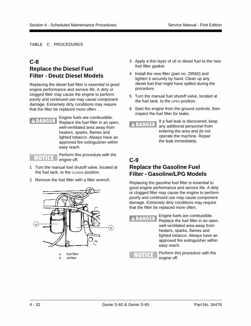
4 - 32 Genie S-60 & Genie S-65 Part No. 34476
Service Manual - First EditionSection 4 - Scheduled Maintenance Procedures
3 Apply a thin layer of oil or diesel fuel to the newfuel filter gasket.
4 Install the new filter (part no. 29560) andtighten it securely by hand. Clean up anydiesel fuel that might have spilled during theprocedure.
5 Turn the manual fuel shutoff valve, located atthe fuel tank, to the OPEN position.
6 Start the engine from the ground controls, theninspect the fuel filter for leaks.
If a fuel leak is discovered, keepany additional personnel fromentering the area and do notoperate the machine. Repairthe leak immediately.
C-8Replace the Diesel FuelFilter - Deutz Diesel ModelsReplacing the diesel fuel filter is essential to goodengine performance and service life. A dirty orclogged filter may cause the engine to performpoorly and continued use may cause componentdamage. Extremely dirty conditions may requirethat the filter be replaced more often.
Engine fuels are combustible.Replace the fuel filter in an open,well-ventilated area away fromheaters, sparks, flames andlighted tobacco. Always have anapproved fire extinguisher withineasy reach.
Perform this procedure with theengine off.
1 Turn the manual fuel shutoff valve, located atthe fuel tank, to the CLOSED position.
2 Remove the fuel filter with a filter wrench.
a fuel filterb oil filter
TABLE C PROCEDURES
a
C-9Replace the Gasoline FuelFilter - Gasoline/LPG ModelsReplacing the gasoline fuel filter is essential togood engine performance and service life. A dirtyor clogged filter may cause the engine to performpoorly and continued use may cause componentdamage. Extremely dirty conditions may requirethat the filter be replaced more often.
Engine fuels are combustible.Replace the fuel filter in an open,well-ventilated area away fromheaters, sparks, flames andlighted tobacco. Always have anapproved fire extinguisher withineasy reach.
Perform this procedure with theengine off.
b

Part No. 34476 Genie S-60 & Genie S-65 4 - 33
Service Manual - First Edition Section 4 - Scheduled Maintenance Procedures
a fuel filterb hose from the fuel pump to
the fuel filter
4 Install the fitting into the new fuel filter, theninstall the fiter into the carburetor.
5 Connect the fuel hose to the filter.
6 Clean up any fuel that may have spilled duringthe installation procedure.
7 Start the machine from the ground controls,then inspect the fuel filter and hose for leaks.
If a fuel leak is discovered, keepany additional personnel fromentering the area and do notoperate the machine. Repairthe leak immediately.
8 Swing the engine pivot plate back to its originalposition and replace the two retaining bolts.
1 Remove the 2 bolts from under the engine pivotplate. Swing the engine pivot plate away fromthe machine to access the fuel filter, locatednear the carburetor.
a pivot plate retaining boltsb engine pivot plate
2 Disconnect the fuel hose from the filter, thenremove the fitting from the filter.
3 Remove the filter from the carburetor.
TABLE C PROCEDURES
ba a
a b
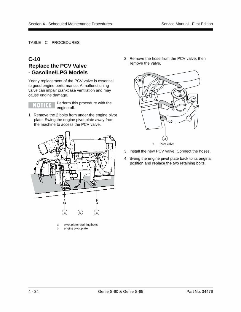
4 - 34 Genie S-60 & Genie S-65 Part No. 34476
Service Manual - First EditionSection 4 - Scheduled Maintenance Procedures
2 Remove the hose from the PCV valve, thenremove the valve.
a PCV valve
3 Install the new PCV valve. Connect the hoses.
4 Swing the engine pivot plate back to its originalposition and replace the two retaining bolts.
C-10Replace the PCV Valve- Gasoline/LPG ModelsYearly replacement of the PCV valve is essentialto good engine performance. A malfunctioningvalve can impair crankcase ventilation and maycause engine damage.
Perform this procedure with theengine off.
1 Remove the 2 bolts from under the engine pivotplate. Swing the engine pivot plate away fromthe machine to access the PCV valve.
a pivot plate retaining boltsb engine pivot plate
TABLE C PROCEDURES
ba a
a
Part No. 34476 Genie S-60 & Genie S-65 4 - 35
Service Manual - First Edition Section 4 - Scheduled Maintenance Procedures
TABLE C PROCEDURES
C-11Replace the Spark Plugs- Gasoline/LPG ModelsPeriodic replacement of the spark plugs isessential to good engine performance andservice life. Worn, loose or corroded spark plugswill cause the engine to perform poorly and mayresult in component damage.
Perform this procedure with theengine off.
1 Label, then disconnect the plug wires from thespark plugs by grasping the molded boot. Donot pull on the plug wire.
2 Blow out any debris around spark plugs.
3 Remove all the spark plugs from the engine.
4 Adjust the gap on each new spark plug.
5 Install the new spark plugs, then connect thewires. Be sure that each spark plug wire isattached to the correct spark plug.
Spark plug specifications
Spark plug type Motorcraft AWSF-52C
Spark plug gap 0.042 to 0.046 inches1.07 to 1.18 mm
Spark plug torque 5 to 10 foot-pounds7 to 14 Nm
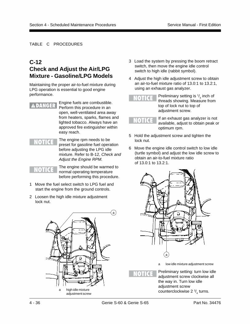
4 - 36 Genie S-60 & Genie S-65 Part No. 34476
Service Manual - First EditionSection 4 - Scheduled Maintenance Procedures
3 Load the system by pressing the boom retractswitch, then move the engine idle controlswitch to high idle (rabbit symbol).
4 Adjust the high idle adjustment screw to obtainan air-to-fuel mixture ratio of 13.0:1 to 13.2:1,using an exhaust gas analyzer.
Preliminary setting is 1/4 inch of
threads showing. Measure fromtop of lock nut to top ofadjustment screw.
If an exhaust gas analyzer is notavailable, adjust to obtain peak oroptimum rpm.
5 Hold the adjustment screw and tighten thelock nut.
6 Move the engine idle control switch to low idle(turtle symbol) and adjust the low idle screw toobtain an air-to-fuel mixture ratioof 13.0:1 to 13.2:1.
a low idle mixture adjustment screw
Preliminary setting: turn low idleadjustment screw clockwise allthe way in. Turn low idleadjustment screwcounterclockwise 2 3/
4 turns.
C-12Check and Adjust the Air/LPGMixture - Gasoline/LPG ModelsMaintaining the proper air-to-fuel mixture duringLPG operation is essential to good engineperformance.
Engine fuels are combustible.Perform this procedure in anopen, well-ventilated area awayfrom heaters, sparks, flames andlighted tobacco. Always have anapproved fire extinguisher withineasy reach.
The engine rpm needs to bepreset for gasoline fuel operationbefore adjusting the LPG idlemixture. Refer to B-12, Check andAdjust the Engine RPM.
The engine should be warmed tonormal operating temperaturebefore performing this procedure.
1 Move the fuel select switch to LPG fuel andstart the engine from the ground controls.
2 Loosen the high idle mixture adjustmentlock nut.
a high idle mixtureadjustment screw
TABLE C PROCEDURES
a
a
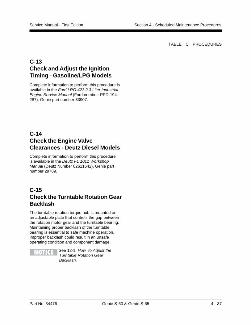
Part No. 34476 Genie S-60 & Genie S-65 4 - 37
Service Manual - First Edition Section 4 - Scheduled Maintenance Procedures
TABLE C PROCEDURES
C-13Check and Adjust the IgnitionTiming - Gasoline/LPG Models
Complete information to perform this procedure isavailable in the Ford LRG-423 2.3 Liter IndustrialEngine Service Manual (Ford number: PPD-194-287). Genie part number 33907.
C-14Check the Engine ValveClearances - Deutz Diesel ModelsComplete information to perform this procedureis available in the Deutz FL 1011 WorkshopManual (Deutz Number 02611642). Genie partnumber 29789.
C-15Check the Turntable Rotation GearBacklashThe turntable rotation torque hub is mounted onan adjustable plate that controls the gap betweenthe rotation motor gear and the turntable bearing.Maintaining proper backlash of the turntablebearing is essential to safe machine operation.Improper backlash could result in an unsafeoperating condition and component damage.
See 12-1, How to Adjust theTurntable Rotation GearBacklash.
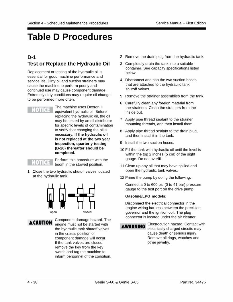
4 - 38 Genie S-60 & Genie S-65 Part No. 34476
Service Manual - First EditionSection 4 - Scheduled Maintenance Procedures
2 Remove the drain plug from the hydraulic tank.
3 Completely drain the tank into a suitablecontainer. See capacity specifications listedbelow.
4 Disconnect and cap the two suction hosesthat are attached to the hydraulic tankshutoff valves.
5 Remove the strainer assemblies from the tank.
6 Carefully clean any foreign material fromthe strainers. Clean the strainers from theinside out.
7 Apply pipe thread sealant to the strainermounting threads, and then install them.
8 Apply pipe thread sealant to the drain plug,and then install it in the tank.
9 Install the two suction hoses.
10 Fill the tank with hydraulic oil until the level iswithin the top 2 inches (5 cm) of the sightgauge. Do not overfill.
11 Clean up any oil that may have spilled andopen the hydraulic tank valves.
12 Prime the pump by doing the following:
Connect a 0 to 600 psi (0 to 41 bar) pressuregauge to the test port on the drive pump.
Gasoline/LPG models:
Disconnect the electrical connector in theengine wiring harness between the precisiongovernor and the ignition coil. The plugconnector is located under the air cleaner.
Electrocution hazard. Contact withelectrically charged circuits maycause death or serious injury.Remove all rings, watches andother jewelry.
D-1Test or Replace the Hydraulic OilReplacement or testing of the hydraulic oil isessential for good machine performance andservice life. Dirty oil and suction strainers maycause the machine to perform poorly andcontinued use may cause component damage.Extremely dirty conditions may require oil changesto be performed more often.
The machine uses Dexron IIequivalent hydraulic oil. Beforereplacing the hydraulic oil, the oilmay be tested by an oil distributorfor specific levels of contaminationto verify that changing the oil isnecessary. If the hydraulic oilis not replaced at the two yearinspection, quarterly testing(B-26) thereafter should becompleted.
Perform this procedure with theboom in the stowed position.
1 Close the two hydraulic shutoff valves locatedat the hydraulic tank.
Component damage hazard. Theengine must not be started withthe hydraulic tank shutoff valvesin the CLOSED position orcomponent damage will occur.If the tank valves are closed,remove the key from the keyswitch and tag the machine toinform personnel of the condition.
Table D Procedures
open closed
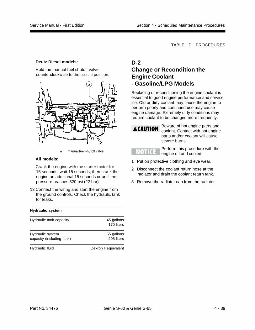
Part No. 34476 Genie S-60 & Genie S-65 4 - 39
Service Manual - First Edition Section 4 - Scheduled Maintenance Procedures
D-2Change or Recondition theEngine Coolant- Gasoline/LPG ModelsReplacing or reconditioning the engine coolant isessential to good engine performance and servicelife. Old or dirty coolant may cause the engine toperform poorly and continued use may causeengine damage. Extremely dirty conditions mayrequire coolant to be changed more frequently.
Beware of hot engine parts andcoolant. Contact with hot engineparts and/or coolant will causesevere burns.
Perform this procedure with theengine off and cooled.
1 Put on protective clothing and eye wear.
2 Disconnect the coolant return hose at theradiator and drain the coolant return tank.
3 Remove the radiator cap from the radiator.
Deutz Diesel models:
Hold the manual fuel shutoff valvecounterclockwise to the CLOSED position.
a manual fuel shutoff valve
All models:
Crank the engine with the starter motor for15 seconds, wait 15 seconds, then crank theengine an additional 15 seconds or until thepressure reaches 320 psi (22 bar).
13 Connect the wiring and start the engine fromthe ground controls. Check the hydraulic tankfor leaks.
Hydraulic system
Hydraulic tank capacity 45 gallons170 liters
Hydraulic system 55 gallonscapacity (including tank) 208 liters
Hydraulic fluid Dexron ll equivalent
TABLE D PROCEDURES
a
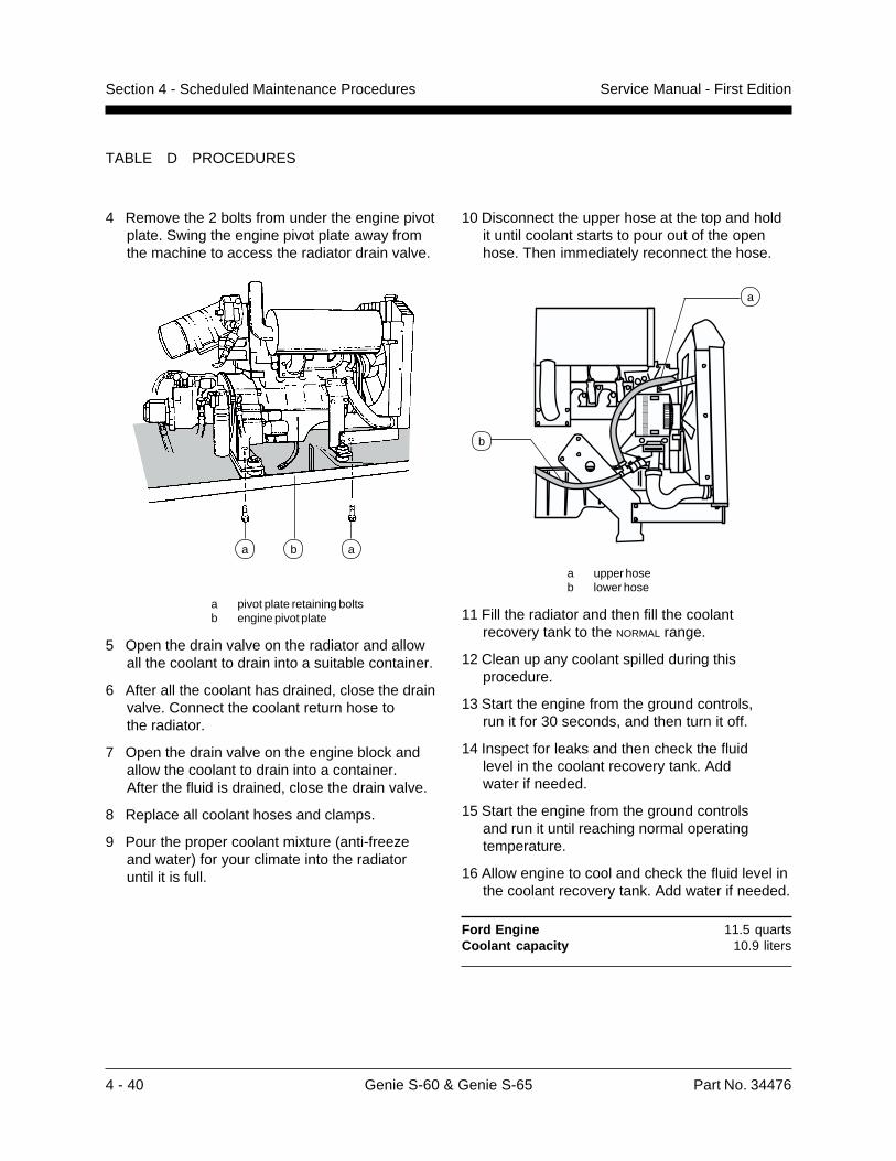
4 - 40 Genie S-60 & Genie S-65 Part No. 34476
Service Manual - First EditionSection 4 - Scheduled Maintenance Procedures
TABLE D PROCEDURES
4 Remove the 2 bolts from under the engine pivotplate. Swing the engine pivot plate away fromthe machine to access the radiator drain valve.
a pivot plate retaining boltsb engine pivot plate
5 Open the drain valve on the radiator and allowall the coolant to drain into a suitable container.
6 After all the coolant has drained, close the drainvalve. Connect the coolant return hose tothe radiator.
7 Open the drain valve on the engine block andallow the coolant to drain into a container.After the fluid is drained, close the drain valve.
8 Replace all coolant hoses and clamps.
9 Pour the proper coolant mixture (anti-freezeand water) for your climate into the radiatoruntil it is full.
10 Disconnect the upper hose at the top and holdit until coolant starts to pour out of the openhose. Then immediately reconnect the hose.
a upper hoseb lower hose
11 Fill the radiator and then fill the coolantrecovery tank to the NORMAL range.
12 Clean up any coolant spilled during thisprocedure.
13 Start the engine from the ground controls,run it for 30 seconds, and then turn it off.
14 Inspect for leaks and then check the fluidlevel in the coolant recovery tank. Addwater if needed.
15 Start the engine from the ground controlsand run it until reaching normal operatingtemperature.
16 Allow engine to cool and check the fluid level inthe coolant recovery tank. Add water if needed.
Ford Engine 11.5 quartsCoolant capacity 10.9 liters
ba a
a
b
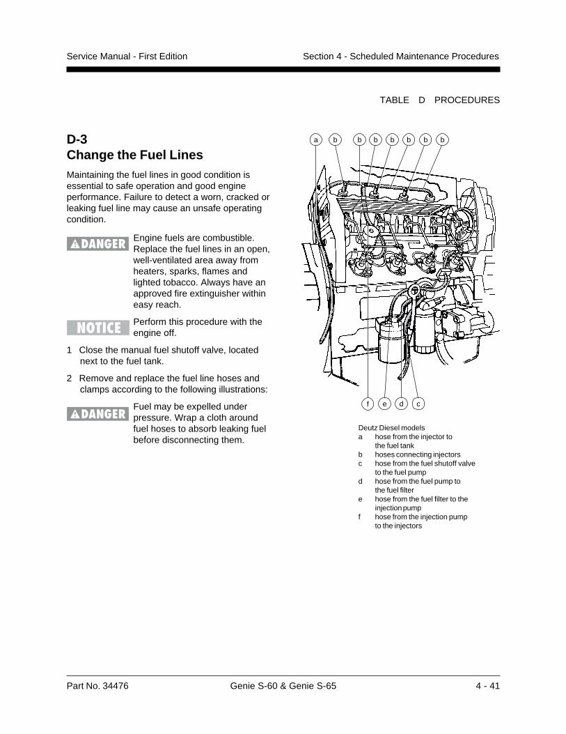
Part No. 34476 Genie S-60 & Genie S-65 4 - 41
Service Manual - First Edition Section 4 - Scheduled Maintenance Procedures
Deutz Diesel modelsa hose from the injector to
the fuel tankb hoses connecting injectorsc hose from the fuel shutoff valve
to the fuel pumpd hose from the fuel pump to
the fuel filtere hose from the fuel filter to the
injection pumpf hose from the injection pump
to the injectors
TABLE D PROCEDURES
D-3Change the Fuel LinesMaintaining the fuel lines in good condition isessential to safe operation and good engineperformance. Failure to detect a worn, cracked orleaking fuel line may cause an unsafe operatingcondition.
Engine fuels are combustible.Replace the fuel lines in an open,well-ventilated area away fromheaters, sparks, flames andlighted tobacco. Always have anapproved fire extinguisher withineasy reach.
Perform this procedure with theengine off.
1 Close the manual fuel shutoff valve, locatednext to the fuel tank.
2 Remove and replace the fuel line hoses andclamps according to the following illustrations:
Fuel may be expelled underpressure. Wrap a cloth aroundfuel hoses to absorb leaking fuelbefore disconnecting them.
b b b b b b
e d cf
ba

4 - 42 Genie S-60 & Genie S-65 Part No. 34476
Service Manual - First EditionSection 4 - Scheduled Maintenance Procedures
a carburetorb fuel filterc hose from the fuel filter to
the fuel pumpd hose from the fuel pump
to the fuel tank (not shown)
3 Clean up any fuel that may have spilled duringthis procedure.
4 Start the engine from the ground controls, theninspect the fuel filter and hoses for leaks.
If a fuel leak is discovered, keepany additional personnel fromentering the area and do notoperate the machine. Repairthe leak immediately.
TABLE D PROCEDURES
D-4Check the Engine ValveClearance - Gasoline/LPG ModelsComplete information to perform this procedure isavailable in the Ford LRG-423 2.3 Liter IndustrialEngine Service Manual (Ford number: PPD-194-287). Genie part number 33907.
D-5Check the Engine CylinderCompression- Gasoline/LPG ModelsComplete information to perform this procedure isavailable in the Ford LRG-423 2.3 Liter IndustrialEngine Service Manual (Ford number: PPD-194-287). Genie part number 33907.
a b c
d
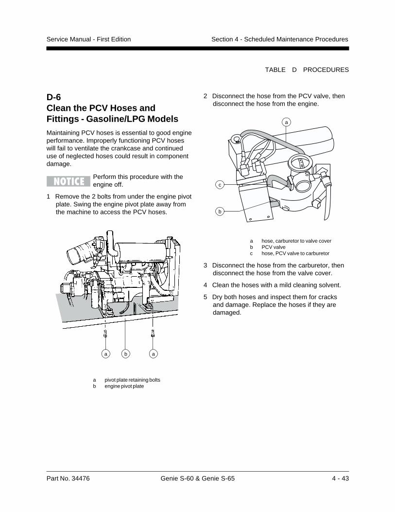
Part No. 34476 Genie S-60 & Genie S-65 4 - 43
Service Manual - First Edition Section 4 - Scheduled Maintenance Procedures
TABLE D PROCEDURES
2 Disconnect the hose from the PCV valve, thendisconnect the hose from the engine.
a hose, carburetor to valve coverb PCV valvec hose, PCV valve to carburetor
3 Disconnect the hose from the carburetor, thendisconnect the hose from the valve cover.
4 Clean the hoses with a mild cleaning solvent.
5 Dry both hoses and inspect them for cracksand damage. Replace the hoses if they aredamaged.
D-6Clean the PCV Hoses andFittings - Gasoline/LPG ModelsMaintaining PCV hoses is essential to good engineperformance. Improperly functioning PCV hoseswill fail to ventilate the crankcase and continueduse of neglected hoses could result in componentdamage.
Perform this procedure with theengine off.
1 Remove the 2 bolts from under the engine pivotplate. Swing the engine pivot plate away fromthe machine to access the PCV hoses.
a pivot plate retaining boltsb engine pivot plate
ba a
c
b
a
4 - 44 Genie S-60 & Genie S-65 Part No. 34476
Service Manual - First EditionSection 4 - Scheduled Maintenance Procedures
D-7Check the Fuel Injection Pumpsand Injectors - Deutz DieselModelsComplete information to perform this procedure isavailable in the Deutz FL 1011 Workshop Manual(Deutz number: 0291 1942). Genie part number29789.
D-8Check the Toothed Belt- Deutz Diesel ModelsComplete information to perform this procedure isavailable in the Deutz FL 1011 Operation Manual(Deutz number: 0297 4706 EN). Genie partnumber 29790.
D-9Replace the Timing Belt- Gasoline/LPG ModelsComplete information to perform this procedure isavailable in the Ford LRG-423 2.3 Liter IndustrialEngine Service Manual (Ford number: PPD-194-287). Genie part number 33907.
TABLE D PROCEDURES
Part No. 34476 Genie S-60 & Genie S-65 5 - 1
Service Manual - First Edition Section 5 - Troubleshooting Flow Charts
Before Troubleshooting:
Read, understand and obey the safety rulesand operating instructions printed in theGenie S-60 & Genie S-65 Operator’s Manual.
Be sure that all necessary tools and testequipment are available and ready for use.
Read each appropiate flow chart thoroughly.Attempting shortcuts may produce hazardousconditions.
Be aware of the following hazards and followgenerally accepted safe workshop practices.
Crushing hazard. When testingor replacing any hydrauliccomponent, always supportthe structure and secure itfrom movement.
Electrocution hazard. Contactwith electrically charged circuitsmay result in death or seriousinjury. Remove all rings, watchesand other jewelry.
Bodily injury hazard. Sprayinghydraulic oil can penetrate andburn skin. Loosen hydraulicconnections very slowly to allowthe oil pressure to dissipategradually. Do not allow oil tosquirt or spray.
Perform all troubleshooting on afirm level surface.
Two persons will be required tosafely perform sometroubleshooting procedures.
Troubleshooting Flow Charts
Observe and Obey:
Troubleshooting and repair procedures shall becompleted by a person trained and qualified onthe repair of this machine.
Immediately tag and remove from service adamaged or malfunctioning machine.
Repair any machine damage or malfunctionbefore operating the machine.
Unless otherwise specified, perform eachrepair procedure with the machine in thefollowing configuration:
· machine parked on a flat level surface
· boom in stowed position
· turntable rotated with the boom between the non-steering wheels
· turntable secured with the turntable rotation lock pin
· key switch in the OFF position with the key removed
· wheels chocked
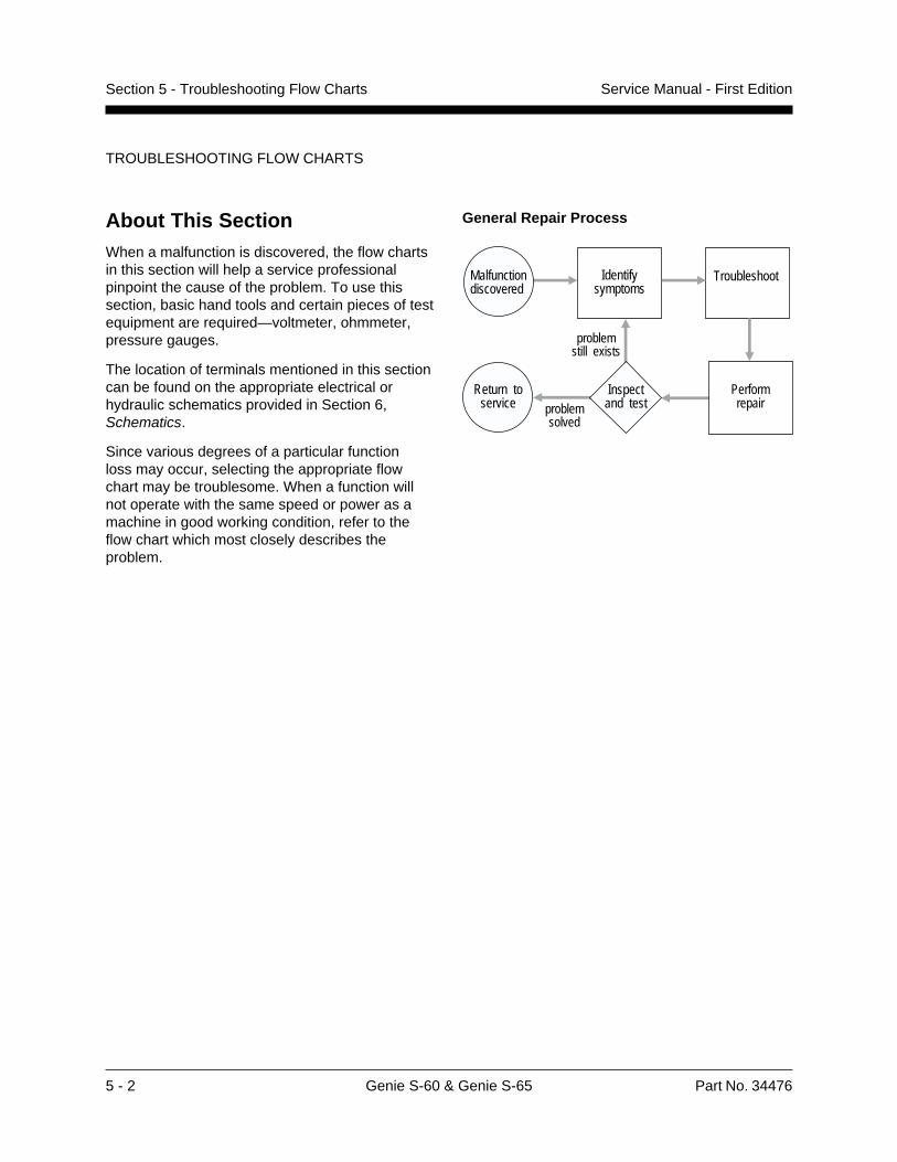
5 - 2 Genie S-60 & Genie S-65 Part No. 34476
Service Manual - First EditionSection 5 - Troubleshooting Flow Charts
General Repair Process
TROUBLESHOOTING FLOW CHARTS
About This SectionWhen a malfunction is discovered, the flow chartsin this section will help a service professionalpinpoint the cause of the problem. To use thissection, basic hand tools and certain pieces of testequipment are required—voltmeter, ohmmeter,pressure gauges.
The location of terminals mentioned in this sectioncan be found on the appropriate electrical orhydraulic schematics provided in Section 6,Schematics.
Since various degrees of a particular functionloss may occur, selecting the appropriate flowchart may be troublesome. When a function willnot operate with the same speed or power as amachine in good working condition, refer to theflow chart which most closely describes theproblem.
Malfunctiondiscovered
Identifysymptoms
Troubleshoot
Performrepair
Return toservice problem
solved
problemstill exists
Inspectand test
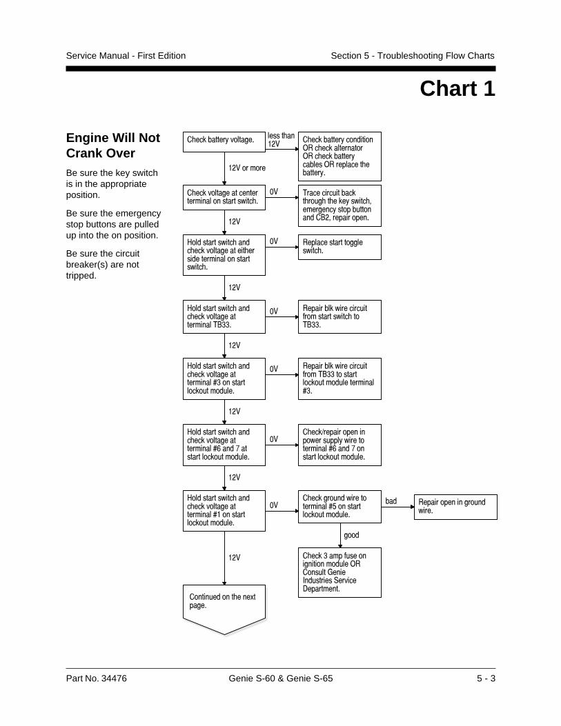
Part No. 34476 Genie S-60 & Genie S-65 5 - 3
Service Manual - First Edition Section 5 - Troubleshooting Flow Charts
Engine Will NotCrank OverBe sure the key switchis in the appropriateposition.
Be sure the emergencystop buttons are pulledup into the on position.
Be sure the circuitbreaker(s) are nottripped.
Chart 1
������������ ����� ������������ ���� ��������������� �������������������������������������
�����������
���� �� �
������� ������������������ �����������
�� ���������������� ���������������� ���������� ���� ������!� ������ �������
" ���������������������� ����������������������� ����������
�� ����������� ����������
���
" ���������������������� ��������������!##�
�� �������������������$ ����������� �!##�
���
" ���������������������� �������������%#� ����� �� ��� �����
�� �������������������$ ���!##� ���� �� ��� �����������%#�
� ������� �������&�����
���
" ���������������������� �������������%'�����(������ �� ��� �����
�������)����� ������� �������������� �������%'�����(� ����� �� ��� �����
���
" ���������������������� �������������%�� ����� �� ��� �����
��������� �������� �������%*� ����� �� ��� �����
��� ������ �������� �������
� �
������#�����$���� ������ ��� �������� �����+����,��������-�����.�������
���
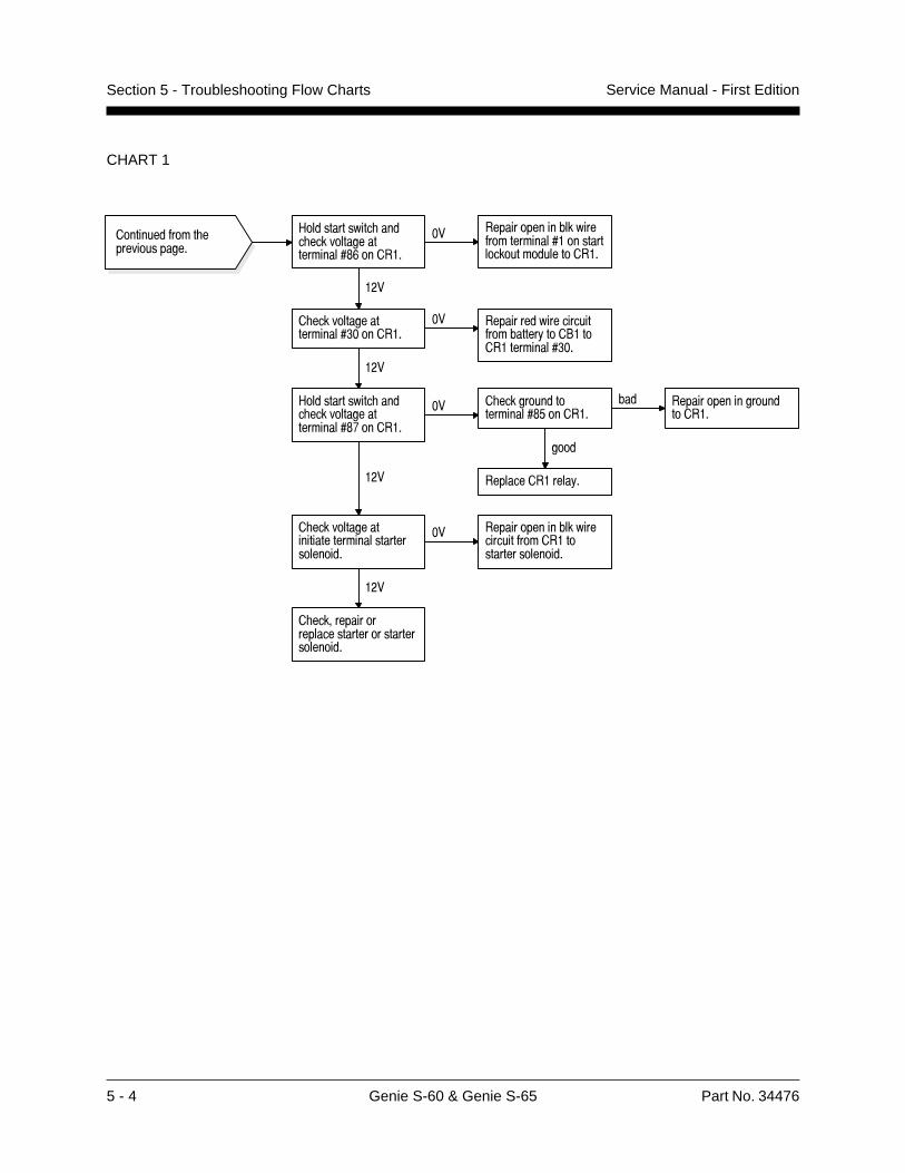
5 - 4 Genie S-60 & Genie S-65 Part No. 34476
Service Manual - First EditionSection 5 - Troubleshooting Flow Charts
CHART 1
������������� ��������������
� ��������������������������������������������
�� ��������������������������������������������������
���
� ��������������������������������������������
� ��������������������� �������
�� �����������������������������!���"��������������� ��
���
#������������� ���� ���������������������$%������
��
��������������!����
#������������� ���� ���������������������$&������
�� ����������������������������������������������������������
���
� ��������������������$'������
����
��� ������������������������
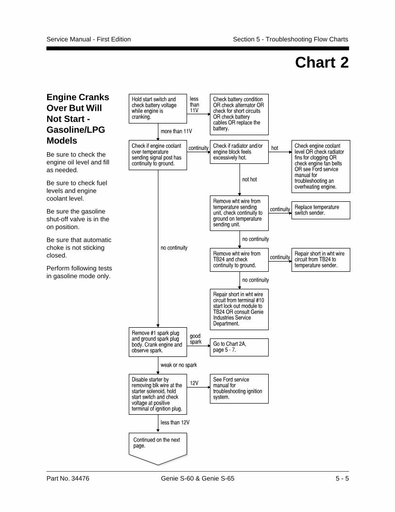
Part No. 34476 Genie S-60 & Genie S-65 5 - 5
Service Manual - First Edition Section 5 - Troubleshooting Flow Charts
Chart 2
Engine CranksOver But WillNot Start -Gasoline/LPGModelsBe sure to check theengine oil level and fillas needed.
Be sure to check fuellevels and enginecoolant level.
Be sure the gasolineshut-off valve is in theon position.
Be sure that automaticchoke is not stickingclosed.
Perform following testsin gasoline mode only.
�������������� ����� ������������������ ���������������������
����� �����
� ������������������������ ���������������� �������� �������������� ���������������������������� ������������� ������
� ������������������������������������������������������ ����������������������
���������� � ����������������� ��������������������!���������� ���
�� � ���������������������������� ������������������������������ ���������������������������"������������������������� ������������ ��������������
���� ��
������� �����������������������������#�� ������������������������������������������������
���������� ��������������������� �������
�������������
������� ��������$%&'������ �����������������������
����������������� ������ ���������������$%&'�������������������
�������������
������� ������ �����������������������(�)�����������������������$%&'������������*����+���������,�����-���������
�������������
�������(���������������������������������������������������������������
�������� *������ ���&.#
�����/���0�
�������������
-���������������������������������� ���������������#� ������������ ������ �����������������������������������������������
�&�,���"������������������������� ����������������������
������ ����&�
�������������� ����!������
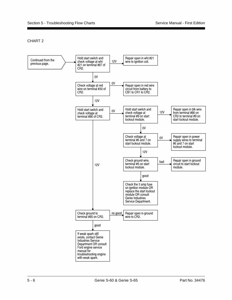
5 - 6 Genie S-60 & Genie S-65 Part No. 34476
Service Manual - First EditionSection 5 - Troubleshooting Flow Charts
CHART 2
������������� ��������������
#������������� ���� ������������� ���������������$%�����
���������������� �����������������������
��
� ������������������������������ ������
�������������������������������������!���"������������
���
#������������� ���� ���������������������$&�����
�� �������������������������������$&����������������(���������������������
���
� ��������������������$'������
������ ����������������������������
����
#������������� ���� ���������������������(���������������������
���
� ���� � ����������������������)��������� �������������������)��������*����+���������,������-����������
��
� ���������������������&���%���������������������
���
�� ����������������������!����������������&���%���������������������
� �����������������������'���������������������
����
��� ����������������������������������������������
+���������������.������������*����+���������,������-���������)��������/�������������������������������� ��������������� ����������
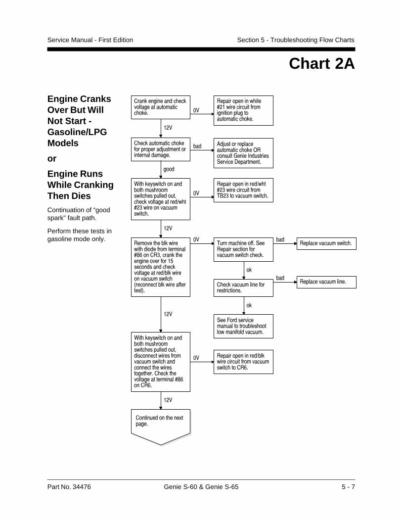
Part No. 34476 Genie S-60 & Genie S-65 5 - 7
Service Manual - First Edition Section 5 - Troubleshooting Flow Charts
Chart 2A
Engine CranksOver But WillNot Start -Gasoline/LPGModels
or
Engine RunsWhile CrankingThen DiesContinuation of “goodspark” fault path.
Perform these tests ingasoline mode only.
0�� ��!����� �������� ��� ��������� ������������� ���������������1� ��� ����������������� �
��
���������������1� ��� ��������������2"� ������������� �
���
������� ����������� �����������������$&���� ������� ��������������'����������� ���������������1�������������������� 3������������������������4�
��2������ �����,���������������������������� � ����
��������������������� �
��
� ����������������������������
���������������������
��
,��/�������������������������� ��������������������
���
0�� ��!����� �������� ��� ��������� ����������������������������������������� ����������� ����������� ���� ���� �������������������$&����&�
�� ���������������1���������������������������� ����&�
���
������������ ���.������
� ������������� �������������5������������������������
��� 6�5���������������������� ���)��������*����+���������,������-����������
��������������� ���������������������� ����
���
��
������������� �������������������������������������������� ����
����
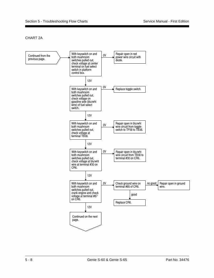
5 - 8 Genie S-60 & Genie S-65 Part No. 34476
Service Manual - First EditionSection 5 - Troubleshooting Flow Charts
CHART 2A
������������� ��������������
0�� ��!����� �������� ��� ��������� ��������������������������� ���������������������$%����&�
�� � ������������������������$'���&�
����
������ �����������������������
���������&�
0�� ��!����� �������� ��� ��������� ������������� ������������������������������������������ ������������������.�
�� ���������������������������������� ������
���
0�� ��!����� �������� ��� ��������� ������������� ������������������������3���1� �����4��������������� �
�������������������� �
���
0�� ��!����� �������� ��� ��������� ������������� ��������������������2" $�
�� ���������������1� �������������������������� ��27 $��2" $�
���
0�� ��!����� �������� ��� ��������� ������������� ���������������1� ���������������� �����&�
���������������1� ���������������2" $����������� �����&�
���
��
������������ ���.������
���
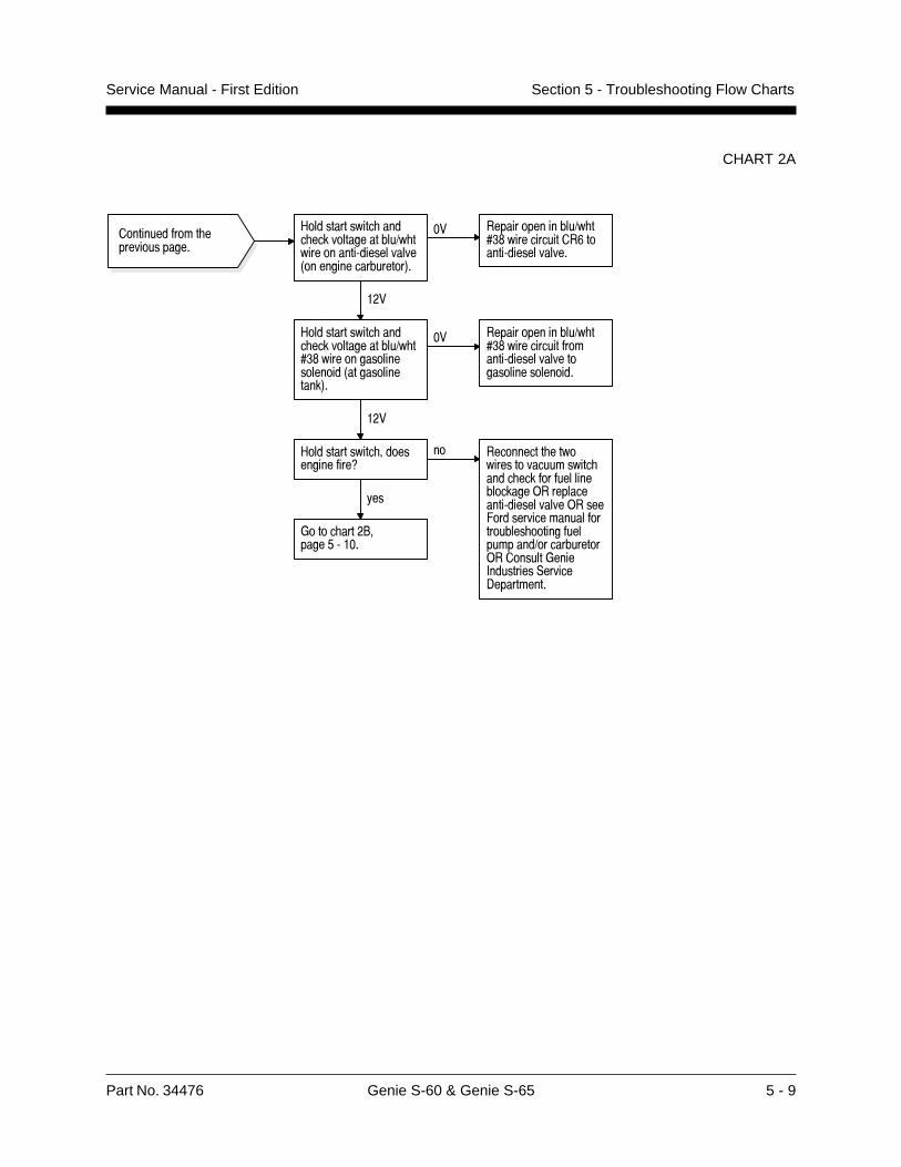
Part No. 34476 Genie S-60 & Genie S-65 5 - 9
Service Manual - First Edition Section 5 - Troubleshooting Flow Charts
CHART 2A
" ���������������������� ����������)������ �����/������������0 �������������� 1�
�� ������ ����������)��%#2�������������'� ���/�������������
���
" ���������������������� ����������)��%#2����� ����� ����� ��� ���0����� �������1�
�� ������ ����������)��%#2�����������$ ����/������������� ��� ������ ��� ���
��� ��������� ����� �����������������������$ �$���������� ������������������/�������������������3 ����������������$ ������ ����$�����������) ������ ���� �����+����,��������-�����.�������
� �������$ �������� ��������
���
" ����������� �� ���������$��4
�
���
+ � ������! �����*�/����
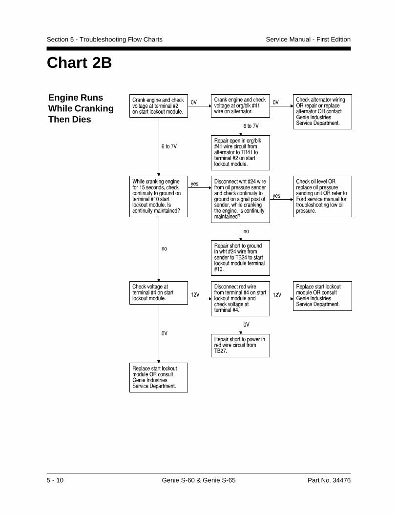
5 - 10 Genie S-60 & Genie S-65 Part No. 34476
Service Manual - First EditionSection 5 - Troubleshooting Flow Charts
Chart 2B
Engine RunsWhile CrankingThen Dies
��������������� �������������������������������������������
�� ��������������� ���������������1����8������������������
�� � �������������������)��������������������������)��������*����+���������,������-����������&��%�
���������������1����8���������������������������2"8����������������������������������
&��%�
0 ��������������������'��������� ������������!����������������������������������������+����������!����������9
!�� -���������� ���8���������������������������� ������������!����������������������������� ������������ ��������+����������!����������9
!��
� �����������)������������������������������)�������/�������������������������� ���������������������
��
������� �������������� ���8���������������2"�8��������������������������������
��
� ���������������������8���������������������
���-����������������������������8������������������������ ���������������������8�
����������������������������)��������*����+���������,������-����������
��
������� �����������������������������2"�%�
��
�������������������������)��������*����+���������,������-����������
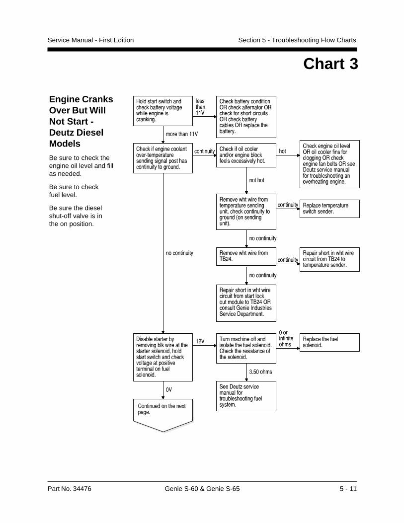
Part No. 34476 Genie S-60 & Genie S-65 5 - 11
Service Manual - First Edition Section 5 - Troubleshooting Flow Charts
Engine CranksOver But WillNot Start -Deutz DieselModelsBe sure to check theengine oil level and fillas needed.
Be sure to checkfuel level.
Be sure the dieselshut-off valve is inthe on position.
Chart 3
#������������� ���� ���������!�������� ��������������������
����� �����
� ���������!���������)�� �������������)�� ������ �����������)�� ���������!������)��������� �������!������ �����
� ���������������������:���������������������������� �����������!���������
���������! � ����������������1������������������.��������! ���
��� �����������������)�����������������������)�� ����������������)����-���;����������������������� ������������ ���������������� ��
������� �������������������������������� ������������!��������3�������������4�
���������! ����������������������� �������
�����������!
������� ��������2"�8� ���������!
������� ������ ���������������2"�8��������������������
�����������!
������� ������ �����������������������������������2"�8)��������*����+���������,������-����������
�����������!
-��������������!������������������ ����������������� ������������� ���� ������������������������������������������
���
,��-���;����������������������� ����������!�����
��
������������ ���.������
2������ ��������������� �������������� ���� ������������� ����������
�'�� ��
����������� ��
�������� �������������

5 - 12 Genie S-60 & Genie S-65 Part No. 34476
Service Manual - First EditionSection 5 - Troubleshooting Flow Charts
CHART 3
� �������$ �������� ��������
" ���������������������� ���������%������� ��������%2(� $�����
��������� ����������%������$ ������� �$���� ��� ���
��
������� ������������� ���������%#�� $����
�������� �������������������$ ������� �!�� ����� �����
���
" ���������������������� �������������%2'� $�����
�� ������ ��������������$ ���������%2'� ����� ��������%5� ����� �� ��� �����
���
������� ���� �������%2*� ������
� �� � ������ �������� ������� �����
� �
" ���������������������� �������������%5� ����� �� ��� �����
���
������#�����$���� ������ ��� ��������������������� �� �� ��������� ����+�����,�������-������.�������
��
������� �������������%'�����(� ����� �� ��� �����
���
�� ������ �������� �������������� �������%'�����(� ����� �� ��� �����
������� ������� �������%*� ����� �� ��� �����
� �
��� ������ �������� ��������� ��������%*� ����� �� ��� �����
� ������� �������&�����
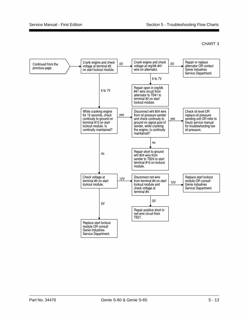
Part No. 34476 Genie S-60 & Genie S-65 5 - 13
Service Manual - First Edition Section 5 - Troubleshooting Flow Charts
CHART 3
��������������� �������������������������������������������
�� ��������������� ���������������1����8������������������
�� �������������������������)��������*����+���������,������-����������
&��%�
���������������1����8���������������������������2"8����������������������������������
&��%�
0 ��������������������'��������� ������������!������������������������������������������+����������!����������9
!��-���������� ���8���������������������������� ������������!����������������������������� ������������ ��������+����������!����������9
!��
� �����������)������������������������������)�������-���;����������������������� ���������������������
��
������� ������������ ���8���������������2"�8����������������������������������
��
� ���������������������8���������������������
��� -����������������������������8������������������������ ���������������������8�
����������������������������)��������*����+���������,������-����������
��
��������������� ����������������������2"�%�
��
�������������������������)��������*����+���������,������-����������
������������� ��������������
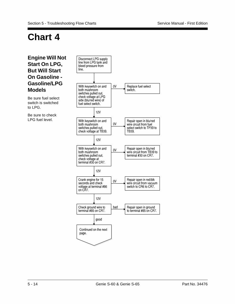
5 - 14 Genie S-60 & Genie S-65 Part No. 34476
Service Manual - First EditionSection 5 - Troubleshooting Flow Charts
Engine Will NotStart On LPG,But Will StartOn Gasoline -Gasoline/LPGModelsBe sure fuel selectswitch is switchedto LPG.
Be sure to checkLPG fuel level.
Chart 4
.��� �����67+������������$ ��67+���������������������$ ������
8������������ ������ ������ ���������������� � ������� �������67+�����0���)������1� $$����������������
�� ��������$���������������
���
8������������ ������ ������ ���������������� � ������� ��������!#5�
�������� ����������)������������$ ��$��������������� ��7#5� �!#5�
���
8������������ ������ ������ ���������������� � ������� �������������%#�� ����(�
�� ������ ����������)������������$ ���!#5� �������%#�� ����(�
���
������������$ ��*��� �������������� ��������������%2' ����(�
�� ������ ���������)�������������$ �������������� ���'� ���(�
���
������� �������� �������%2*� ����(�
��� ������ �������� ��� ��������%2*� ����(�
� �
� ������� �������&�����
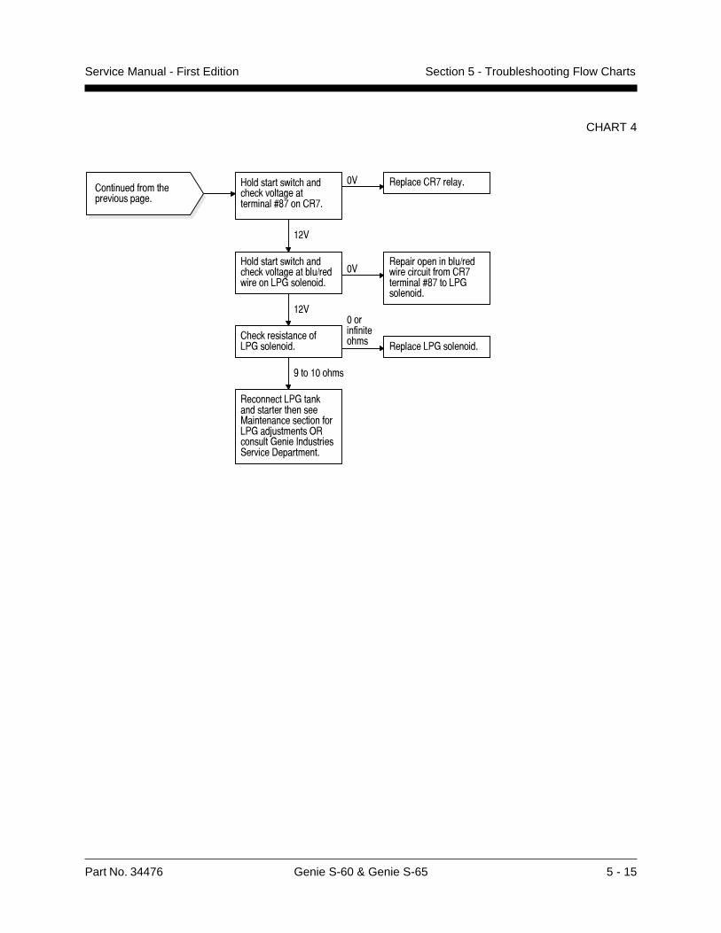
Part No. 34476 Genie S-60 & Genie S-65 5 - 15
Service Manual - First Edition Section 5 - Troubleshooting Flow Charts
CHART 4
������������� ��������������
#������������� ���� ���������������������$%����%�
�� ���������%����!�
#������������� ���� ���������������1���������<7*���������
�����������������1�������������������%���������$%��<7*���������
���
� ��������������<7*���������
����������� �� �������<7*���������
(����� ��
���������<7*��������������� �����=�������������������<7*��5��������)��������*����+���������,������-����������
���
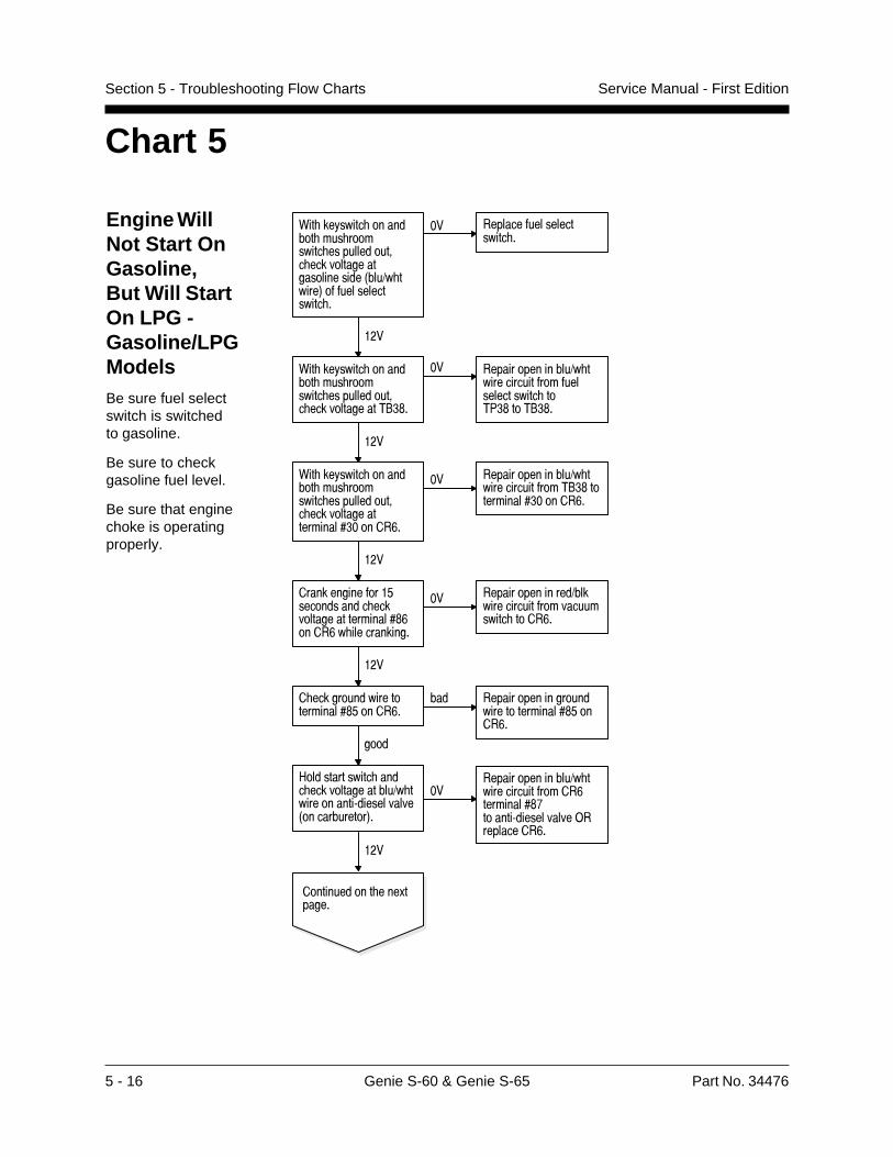
5 - 16 Genie S-60 & Genie S-65 Part No. 34476
Service Manual - First EditionSection 5 - Troubleshooting Flow Charts
Chart 5
Engine WillNot Start OnGasoline,But Will StartOn LPG -Gasoline/LPGModelsBe sure fuel selectswitch is switchedto gasoline.
Be sure to checkgasoline fuel level.
Be sure that enginechoke is operatingproperly.
1�� �������� ���������� ���� ������� �������������#� ����������������������������2��� ���3������������������� �
)� ����������������������� �
�&�
1�� �������� ���������� ���� ������� �������������#� ���������������$%45�
)� ����������������� ������������������������������ ���$645����$%45�
�&�
�������������� ����� ������������������ ������������������������2����������3�
)������������������ �����������������7��������(50��������������������������������7�
�&�
1�� �������� ���������� ���� ������� �������������#� ����������������������(4)������7�
)� ����������������� ���������������$%45�����������(4)������7�
�&�
����������������/������������� ����������������������(57�����7� ������������
)� ���������������� ��������������������������� ������7�
�&�
� �����������������������(5/������7�
��� ���������������������������������(5/�����7�
����
�������������� ����!������
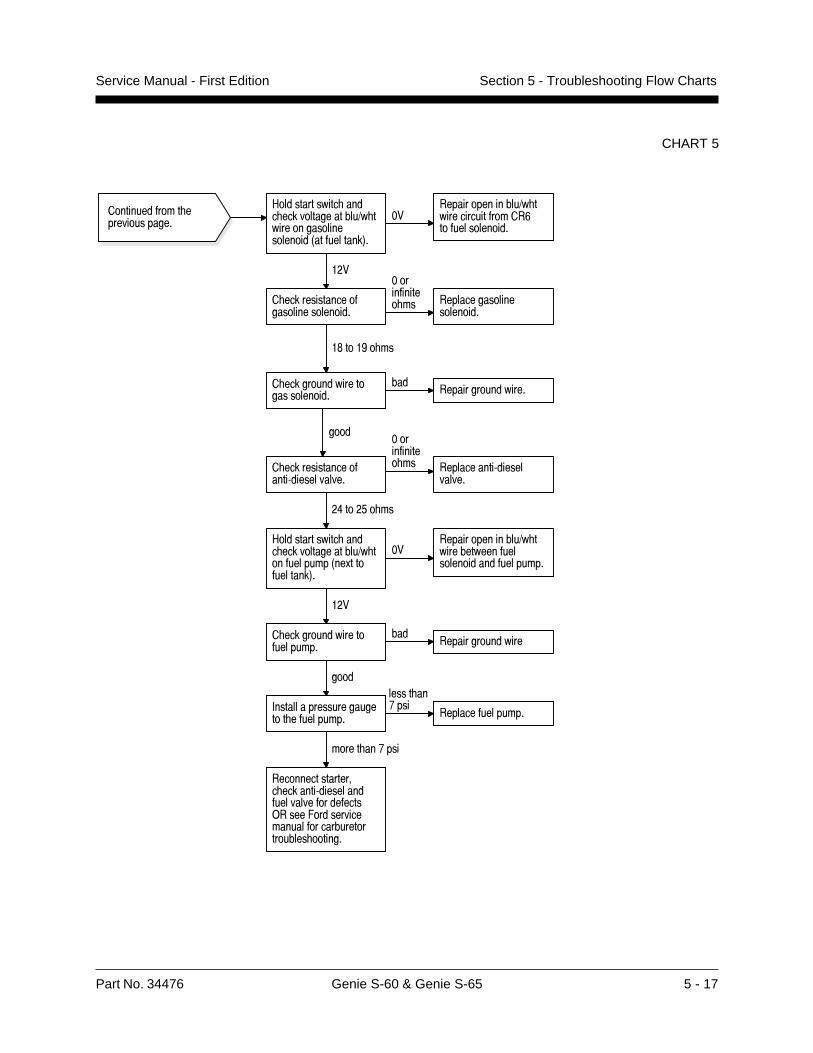
Part No. 34476 Genie S-60 & Genie S-65 5 - 17
Service Manual - First Edition Section 5 - Troubleshooting Flow Charts
CHART 5
#������������� ���� ���������������1� �����������������������3���������4�
�����������������1� �����������������&��������������
���
� �������������������������������
����������� �� ���������������
���������
�$���(� ��
� ������������������:������������
����������� �� �����������:������
������
�8���'� ��
������������������ �������:�������������������������)����/������������������������������������ �������
� ���������������������������
��������������������
����
������������� ��������������
#������������� ���� ���������������1� ����������3��.����������4�
�����������������1� ����������������������������������
���
� �����������������������
�������������������
����
+����������������������� ���������
����� ��%���
���������������
����� ��%���
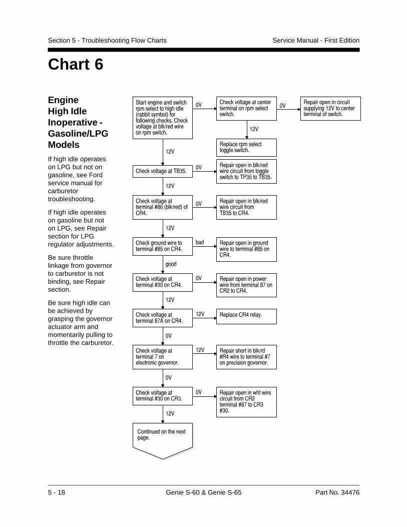
5 - 18 Genie S-60 & Genie S-65 Part No. 34476
Service Manual - First EditionSection 5 - Troubleshooting Flow Charts
Chart 6
EngineHigh IdleInoperative -Gasoline/LPGModelsIf high idle operateson LPG but not ongasoline, see Fordservice manual forcarburetortroubleshooting.
If high idle operateson gasoline but noton LPG, see Repairsection for LPGregulator adjustments.
Be sure throttlelinkage from governorto carburetor is notbinding, see Repairsection.
Be sure high idle canbe achieved bygrasping the governoractuator arm andmomentarily pulling tothrottle the carburetor.
,������������������ ����������� �� ����3�������!����4����������� ������ ���������������1����������������� �
�� � ������������������������������������������ �
�� ������������������������!���������������������������� �
���
��������������������������� ����
� ������������2" '��� ���������������1���
������������������������� ��27 '��2" '�
���
� ���������������������$&3���1���4���8�
�� ���������������1�����������������2" '����8�
���
������������ ���.������
� ��������������������� ����� �
�� ������������� ���������������������������$%���� � �����
� ������������������������$'����8�
��� ���������������������������������$'����8�
����
� ��������������������� �����8�
�� ��������������������������������$%���������8�
���
� ��������������������$%6����8�
��� ���������8����!�
��
� ��������������������%���������������������
��� ������� ��������1����8���������������%��������������������
��
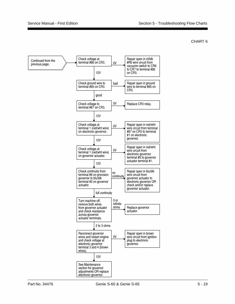
Part No. 34476 Genie S-60 & Genie S-65 5 - 19
Service Manual - First Edition Section 5 - Troubleshooting Flow Charts
CHART 6
������������� ��������������
2������ �������������� ���������������������������� ���������������������������������������������
����������� �� ���������������
���������
��� � ��
������������������������������������������ �������������������������������������� ���83����������4�
������������������������������������������������������������������
���
,��=�����������������������������5��������)���������������������������
���������������1� ������������������������$%���� ���������������������������������
� ���������������������3���1� �����4���������������������
��
���
� ���������������������3���1� �����4�������������������
�����������������1� ������������������������������������������'�����������������������������
���
� ������������!������������&������������������������1��������������������������������
�����������!
���������������1�����������������������������������������������������)�� ������1��������������������������
������������!
� ���������������������$&���� � ��
��������������1�����&�������������������������� ����&����%�����������$&���� ����
� ������������������������$'���� �
��� ���������������������������������$'���� �
����
� ���������������������$%���� �
�� ��������� ����!�
���

5 - 20 Genie S-60 & Genie S-65 Part No. 34476
Service Manual - First EditionSection 5 - Troubleshooting Flow Charts
Engine Low IdleInoperative -Gasoline/LPGModelsIf low idle operateson LPG but not ongasoline, see Fordservice manual forcarburetortroubleshooting.
If low idle operateson gasoline but noton LPG, see Repairsection for LPGregulator adjustments.
Be sure throttlelinkage from governorto carburetor is notbinding, see Repairsection.
Chart 7
,������������������ ������������������3�������!����4�� ���������������������$&3���1������4����8�
���+������� ������������������������� ���� ��������������!����������������������� �
��
� ���������������������%���������������������
�� ���������������1�������������������8���������$%6�����������������������������%����
� �������������������������������������� ���83����������4�
�� ������������������������������������������������������������������
���
2������ ��������������1�������������������&�������������������������������������
������������ �� ������� ���� �������������3����������������4)�� ������1�������������������������)����/������������������������������������ ��������������������������
��� �����������������������5��������)���������������������������
� ��������������������� �����8�
�� ������������� ������������������������$%���������8��������� �����
� ���������������������$%6����8�
�� ���������8����!�
���
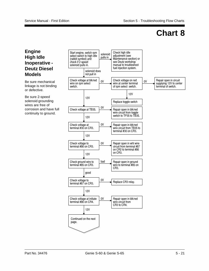
Part No. 34476 Genie S-60 & Genie S-65 5 - 21
Service Manual - First Edition Section 5 - Troubleshooting Flow Charts
Chart 8
EngineHigh IdleInoperative -Deutz DieselModelsBe sure mechanicallinkage is not bindingor defective.
Be sure 2-speedsolenoid groundingwires are free ofcorrosion and have fullcontinuity to ground.
-�������� ��������������������� ����������0��������� �1�����������$��/������ ��� ������������
� ��� ����������
�����������������9������0���:�������������� �1� ����.��;�� ��� �������� � ������ $������9��� ��������
� ��� ���� ��� ��������
������� ����������)������ ����������������
�� ������� ����� ��������������������� $�����������������
�� ������ �������������������������� ������������ $�������
���
�������� �������������
������� ��������!#*���
������ ����������)������������$ �� ���������� ��7#*� ��!#*����
������� ��������������������%2'� ����<�
�� ������ ����������)������������$ ���#� ���<�
������� �������������%#�� ����#�
�� ������ ����������)������������$ ���!#*� �������%#�� ����#�
���
������� ����� �������%2'� ����#�
���
�� ������ �������������������$ ���������%2( ������ ��������%2' ����#�
������� �������� �������%2*� ����#�
��� ������ �������� ������� ��������%2*� ���#�
� �
������� ����� �������%2(� ����#�
������������#������
���
���
� ������� �������&�����
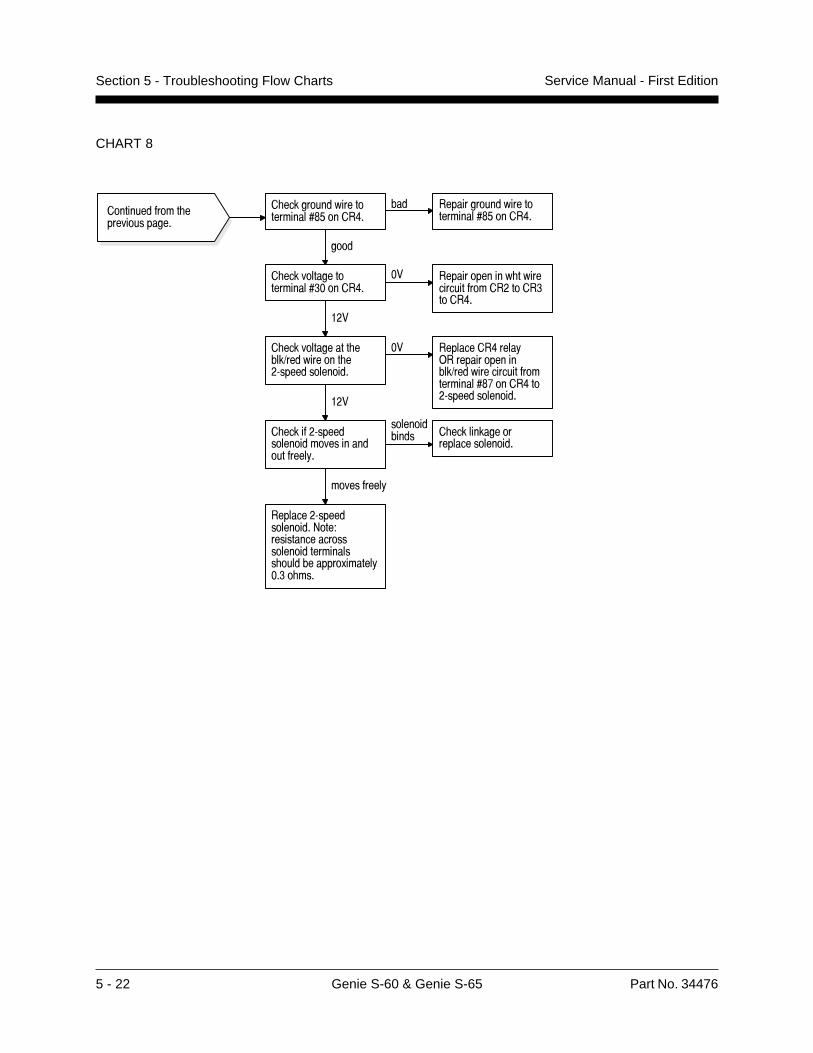
5 - 22 Genie S-60 & Genie S-65 Part No. 34476
Service Manual - First EditionSection 5 - Troubleshooting Flow Charts
CHART 8
� ������������� ����1���������� ��:��������������
�� ���������8����!)����������������1��������������������������$%����8���:�����������������
� �����:������������������������������!�
������������� � ������������
����������������
���������!
��������:��������������>���?���������������������������������� �����������.������!�� � ���
������������� ��������������
� ������������������������$'����8�
��� ���������������������������$'����8�
����
� ��������������������� �����8�
�� ������������� ���������������������� ����8�
���
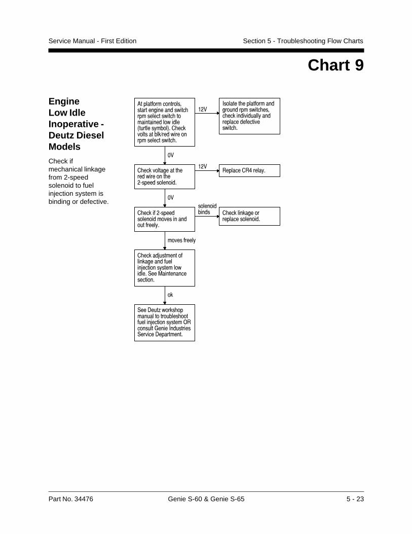
Part No. 34476 Genie S-60 & Genie S-65 5 - 23
Service Manual - First Edition Section 5 - Troubleshooting Flow Charts
Chart 9
EngineLow IdleInoperative -Deutz DieselModelsCheck ifmechanical linkagefrom 2-speedsolenoid to fuelinjection system isbinding or defective.
6������������������������������������ �������������� �������������������3�������!����4�� �������������1����������������������� �
���+������� ������������������������� ���� ��������������!����������������������� �
��
� ������������� ����������� ��:��������������
������������8����!�
��
� �����:������������������������������!�
������������� � ������������
����������������
���������!
� �����5�����������������������5�������!������������,��=������������������
��
,��-���;����� ������������������ ��������5�������!����)��������*����+���������,������-����������
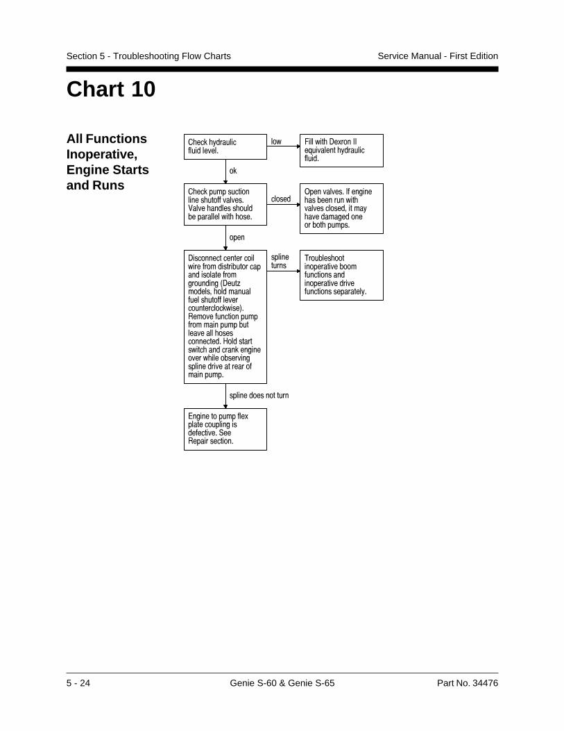
5 - 24 Genie S-60 & Genie S-65 Part No. 34476
Service Manual - First EditionSection 5 - Troubleshooting Flow Charts
Chart 10
All FunctionsInoperative,Engine Startsand Runs
� ��� !�����������������
��� /������ -�.���++�@�������� !������������
��
� ������������������� ��������������� ������� ����������������� ����
������)����������+������ ������������ �����������������! ������������������ ������
����
-��������������������������������������������������������������3-���;������� ������������� ������������������������4���������������������������������������� ��������������#������������� ������������������� ���������������������������������������
�����������
2������� ��������������������������������������������������������������!�
�����������������
A�������������.������������������������,����������������
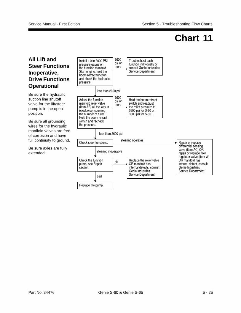
Part No. 34476 Genie S-60 & Genie S-65 5 - 25
Service Manual - First Edition Section 5 - Troubleshooting Flow Charts
Chart 11
All Lift andSteer FunctionsInoperative,Drive FunctionsOperationalBe sure the hydraulicsuction line shutoffvalve for the lift/steerpump is in the openposition.
Be sure all groundingwires for the hydraulicmanifold valves are freeof corrosion and havefull continuity to ground.
Be sure axles are fullyextended.
+���������� ���7,+���������������� ����������������,����������� ���� ����������������������� ���� � !����������������
�&�����������
2������� ������ ������������������!���������*����+���������,������-����������
����� ���&�����
6�5���� �������������������������3����6"4���� ���!��3���������4��������� ��������������#���� ����������������� ������ ���� ����������
�&�����������
#���� ����������������� �������5���� �����������������&�������,:&��� ��������,:&'�
����� ���&�����
� ���� ������������������������������
�� �������� �����������)�������� ������������������������*����+���������,������-�������������
�������� ������
� ���������������������������������
�������������������������������������3����6�4)���������������������������������3����04)�������� �����������������������*����+���������,������-����������
�������������������
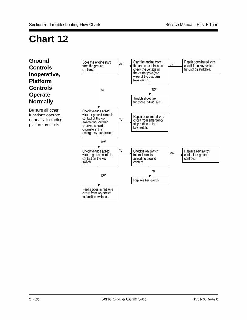
5 - 26 Genie S-60 & Genie S-65 Part No. 34476
Service Manual - First EditionSection 5 - Troubleshooting Flow Charts
Chart 12
GroundControlsInoperative,PlatformControlsOperateNormallyBe sure all otherfunctions operatenormally, includingplatform controls.
-���� ���������������� ���������������9
!�� ,����� ����������� ������������������� ���� ����������� �����������3�������4�� ������������������ �
�� �������������������������������!����� �������������� ���
���
2������� ���� ��������������������!�
��
� �������������������������������������������� ���!����� 3� ��������� ������ ���������������� ���������!����������4�
���������������������������������������!������������� ���!����� �
���
� ��������������������������������������������� ���!����� �
�� � ������!����� �������������������������������������
!�� ���������!����� ������������������������
��
���������!����� ����
�������������������������������!����� �������������� ���
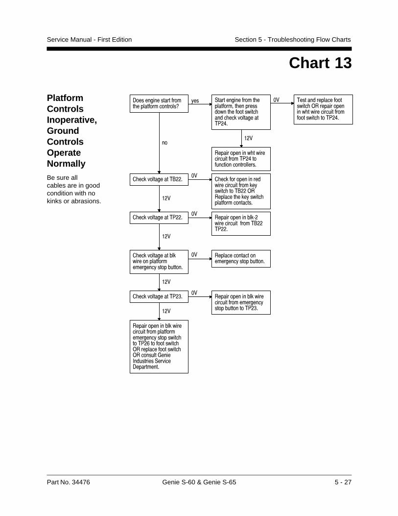
Part No. 34476 Genie S-60 & Genie S-65 5 - 27
Service Manual - First Edition Section 5 - Troubleshooting Flow Charts
Chart 13
PlatformControlsInoperative,GroundControlsOperateNormallyBe sure allcables are in goodcondition with nokinks or abrasions.
-������������������ ����������������9
!�� ,�������������� ���������� ������������ ��������� ���� ������������27�8�
�� 2��������������������� )�������������� ����������������������� ��27�8�
���
������������� ���������������27�8���������������������
��
� ������������2"�����
� ������������������������������!����� ��2"��)��������� ���!����� ����������������
���
� ������������27�����
���������������:���������������2"��27���
���
� ������������������������������������!�����������
�� ������������������������!�����������
���
� ������������27� ���
�������������������������������������!������������27� ����
��������������������������������������������!��������� ��27�&���������� )���������������� )��������*����+���������,������-����������
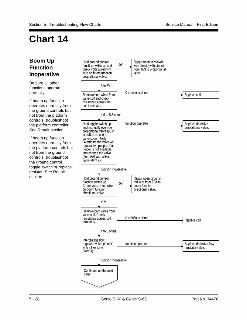
5 - 28 Genie S-60 & Genie S-65 Part No. 34476
Service Manual - First EditionSection 5 - Troubleshooting Flow Charts
Chart 14
Boom UpFunctionInoperativeBe sure all otherfunctions operatenormally.
If boom up functionoperates normally fromthe ground controls butnot from the platformcontrols, troubleshootthe platform controller.See Repair section.
If boom up functionoperates normally fromthe platform controls butnot from the groundcontrols, troubleshootthe ground controltoggle switch or replaceresistor. See Repairsection.
" ���� ����� � �$���� ��������������������� �������)������ ��� ��$���� �� � � ����������
�������� ���������)������������0������ ��1$ ���!#� �� � � ���������
#� �'�
��� ���� �������$ �������� ����������������������� ������ �����������
�� ���$����� ���
����������$������ � � ����������
<�*� �*�*� ���
" ��� �������������������������� ������ � � ����������0��������� �� ������ $�������� �1��= �>�����������������������?����� ��� �����,$������������ ���������� ������������������0����@@1�����������������0����A1�
$���� �� �����
��������� ��
,���������$� ������ �������0����B1����������������0����C1�
$���� ���� ������
$���� �� ����� ����������$������$� ������ �������
� ������� �������&�����
$���� ���� ������
" ���� ����� � �$���� ������������������ ����������� ��� ��$���� ������ ����������
�������� �������������������$ ���!�� � ��$���� ������ ����������
���
��� ���� �������$ �������� �������������������� ���� ����������
�� ���$����� ������������ ���
<� �*� ���
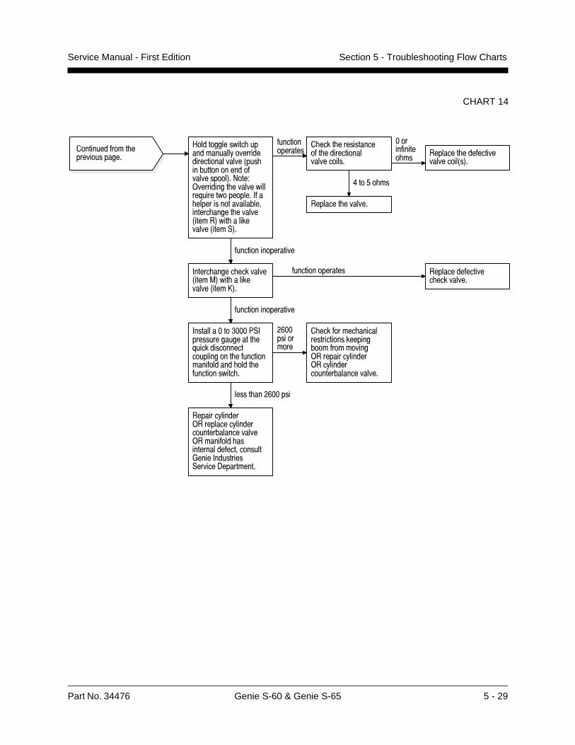
Part No. 34476 Genie S-60 & Genie S-65 5 - 29
Service Manual - First Edition Section 5 - Troubleshooting Flow Charts
CHART 14
#�������������� ������������!������������������������3��� ������������������������4�>���?)���������� ������������@��������������+� �������������������������� ����� ������3�����4��� ����������3����,4�
������������� ��������������
���������������
� ���� ������������� �����������������������
����������� �� �������� ���������
���������3�4�
8��'� ��
�������� �������
������������������
+����� ����� ��������3����=4��� ����������3����B4�
��������������� ���������������� ���������
������������������
+���������� ���7,+���������������� �@������������������������� ������������������ ���� ������������� �
�&�����������
� �������� ��������������������������������������)��������!������)��!��������������������������
����� ���&�����
�������!������)���������!�������������������������)�������� �����������������������*����+���������,������-����������
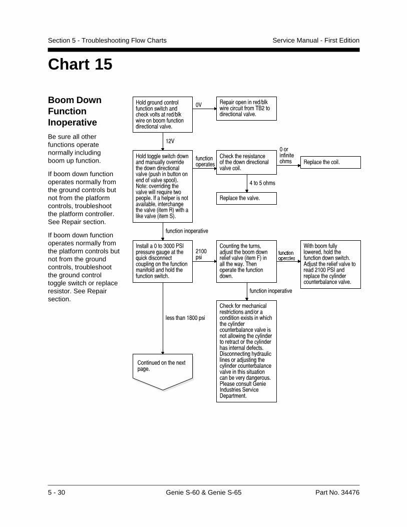
5 - 30 Genie S-60 & Genie S-65 Part No. 34476
Service Manual - First EditionSection 5 - Troubleshooting Flow Charts
Boom DownFunctionInoperativeBe sure all otherfunctions operatenormally includingboom up function.
If boom down functionoperates normally fromthe ground controls butnot from the platformcontrols, troubleshootthe platform controller.See Repair section.
If boom down functionoperates normally fromthe platform controls butnot from the groundcontrols, troubleshootthe ground controltoggle switch or replaceresistor. See Repairsection.
Chart 15
#���������������������������� ���� �������������1�������������������������������������
�� ���������������1�����������������2"��������������������
���
#�������������� ��������������!��������� ���������������������3��� ������������������������4�>���?����������� ������������@��������������+� �������������������������� ����� ������3�����4��� ����������3����,4�
���������������
� ���� ������������� ��������������������������
����������� ��
8��'� ��
�������� ������
�������� �������
������������������
+���������� ���7,+���������������� �@������������������������� ������������������ ���� ������������� �
�������
��������� ���������5���� �������������������3����/4������ ���!�2 ���������� �������������
L[TIZOUTUVKXGZKY
� �������� ���������������������1�������������.������� �� � ��!��������������������������������������� ��!������������������ ��!������ �����������������-������������ !����������������5������� ��!���������������������������� �������������������!����������7������������*����+���������,������-����������
������������������
0�� �������!�������� ���� ����������������� �6�5���� ���������������������7,+����������� ��!��������������������������
����� ���$�����
������������ ���.������
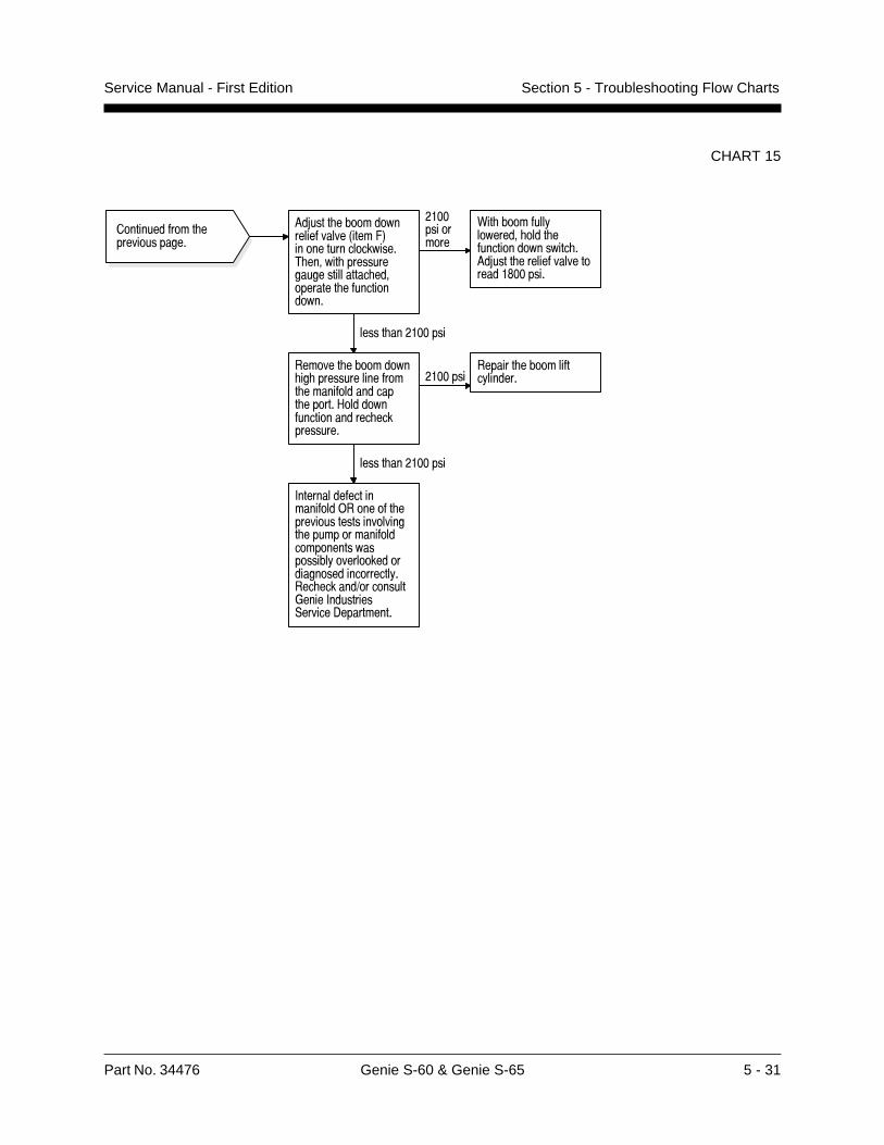
Part No. 34476 Genie S-60 & Genie S-65 5 - 31
Service Manual - First Edition Section 5 - Troubleshooting Flow Charts
CHART 15
��������������� ��������������
.�8����� ����������������������2�����"3��������������������$ ��#��� ������������������������ ��#�������� ��������������
&�))��������
1�� ����������������#� ����� ������������������ �.�8����� ���������������������5))�����
������ ���&�))����
�������� ���������� �� ����������������� ������������������� ������������������������������ ����������
&�))����������� �������������������
������ ���&�))����
+������������������������������������ ������������������������� ������������������������������������������������������������������������� ������� ���������*�����+��������,������-���������
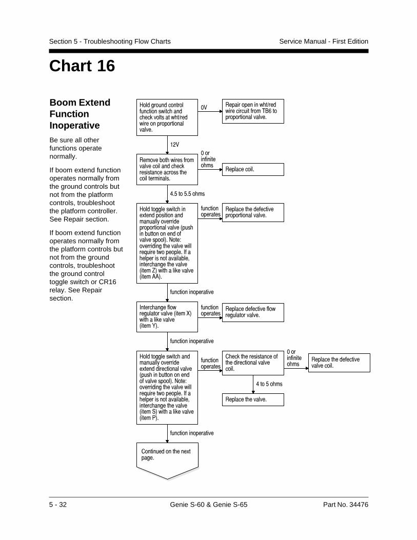
5 - 32 Genie S-60 & Genie S-65 Part No. 34476
Service Manual - First EditionSection 5 - Troubleshooting Flow Charts
Chart 16
Boom ExtendFunctionInoperativeBe sure all otherfunctions operatenormally.
If boom extend functionoperates normally fromthe ground controls butnot from the platformcontrols, troubleshootthe platform controller.See Repair section.
If boom extend functionoperates normally fromthe platform controls butnot from the groundcontrols, troubleshootthe ground controltoggle switch or CR16relay. See Repairsection.
#���������������������������� ���� ����������� �1���������������������������
�� ������������� �1�����������������2"&��������������������
���
��������� ��������������������� �������������������� ���������������
����������� ��
������������
8�'��'�'� ��
#�������������� ���.����������������������!�������������������������3��� ������������������������4�>���?����������� ������������@��������������+� �������������������������� ����� ������3����C4��� ����������3����664�
���������������
�������� ���������������������������
������������������
+����� ���������������������3����D4��� ����������3����E4�
���������������
���������������������������������
������������������
#�������������� ����������!���������.��������������������3��� ������������������������4�>���?����������� ������������@��������������+� �������������������������� ����� ������3����,4��� ����������3����74�
���������������
� ���� ������������� ����������������������
8��'� ��
�������� �������
����������� ��
�������� �������������������
������������������
������������ ���.������
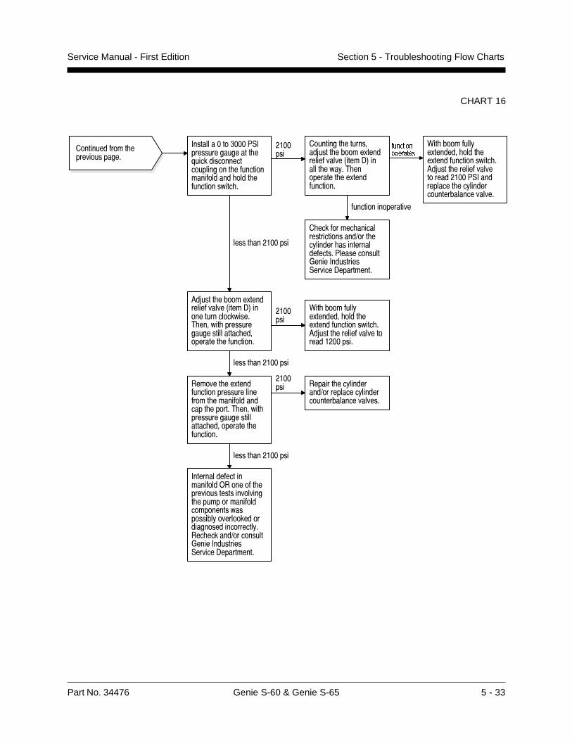
Part No. 34476 Genie S-60 & Genie S-65 5 - 33
Service Manual - First Edition Section 5 - Troubleshooting Flow Charts
CHART 16
������������� ��������������
+���������� ���7,+���������������� �@������������������������� ������������������ ���� ������������� �
�������
��������� ���������5���� ������.��������������3����-4������ ���!�2 ���������� ��.������������
L[TIZOUTUVKXGZKY
� �������� ���������������������1��� ��!������ �����������������7������������*����+���������,������-����������
������������������
0�� �������!�.������� ���� ��.���������������� �6�5���� ���������������������7,+����������� ��!��������������������������
����� ���������
6�5���� ������.��������������3����-4�������������������2 ������ ����������������������� ����������� ���������
�������
0�� �������!�.������� ���� ��.���������������� �6�5���� �������������������������
����� ���������
������� ��.��������������������������� ��������������� ������2 ������ ����������������������� ����������� ���������
������� ������� ��!������
���1����������!���������������������������
����� ���������
+���������������������)������ ������������������������ ����������������������������������!�������������������������������!���� ������1���������*����+���������,������-����������
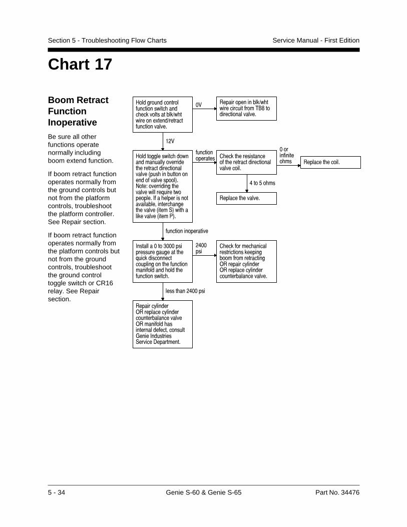
5 - 34 Genie S-60 & Genie S-65 Part No. 34476
Service Manual - First EditionSection 5 - Troubleshooting Flow Charts
Chart 17
Boom RetractFunctionInoperativeBe sure all otherfunctions operatenormally includingboom extend function.
If boom retract functionoperates normally fromthe ground controls butnot from the platformcontrols, troubleshootthe platform controller.See Repair section.
If boom retract functionoperates normally fromthe platform controls butnot from the groundcontrols, troubleshootthe ground controltoggle switch or CR16relay. See Repairsection.
#���������������������������� ���� �������������1� ��������.����1��������������������
�� ���������������1� ���������������2"$�������������������
���
#�������������� ��������������!��������� ������������������������3��� ������������������������4�>���?����������� ������������@��������������+� �������������������������� ����� ������3����,4��� ����������3����74�
��������������� � ���� �����������
�� �����������������������������
����������� �� �������� ������
8��'� ��
�������� �������
������������������
+���������� ���������������������� �@������������������������� ������������������ ���� ������������� �
�8�����
� �������� ������������������������������������������)��������!������)���������!��������������������������
����� ���8�����
�������!������)���������!�������������������������)�������� �����������������������*����+���������,������-����������
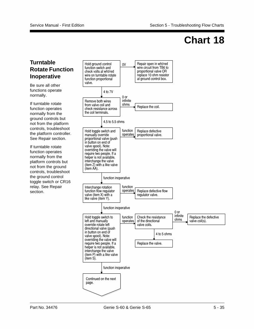
Part No. 34476 Genie S-60 & Genie S-65 5 - 35
Service Manual - First Edition Section 5 - Troubleshooting Flow Charts
Chart 18
TurntableRotate FunctionInoperativeBe sure all otherfunctions operatenormally.
If turntable rotatefunction operatesnormally from theground controls butnot from the platformcontrols, troubleshootthe platform controller.See Repair section.
If turntable rotatefunction operatesnormally from theplatform controls butnot from the groundcontrols, troubleshootthe ground controltoggle switch or CR16relay. See Repairsection.
#���������������������������� ���� ����������� �1�������������������������������������������������
�� ������������� �1�����������������2"&�������������������)����������� ��������������������������.�
8��%�
��������� ��������������������� �������������������� ���������������
����������� ��
�������� ������
8�'��'�'� ��
#�������������� ����������!�������������������������3��� ������������������������4�>���?����������� ������������@��������������+� �������������������������� ����� ������3����C4��� ����������3����664�
���������������
���������������������������������
������������������
+����� ������������������������������������3����D4��� ����������3����E4�
��������������� ������������������
���������������
������������������
#�������������� ���������������!���������������������������������3��� ������������������������4�>���?����������� ������������@��������������+� �������������������������� ����� ������3����74��� ����������3����,4�
���������������
� ���� ������������� �����������������������
8��'� ��
�������� �������
����������� ��
�������� ������������������3�4�
������������������
������������ ���.������
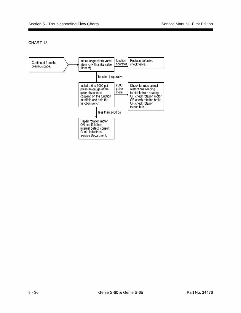
5 - 36 Genie S-60 & Genie S-65 Part No. 34476
Service Manual - First EditionSection 5 - Troubleshooting Flow Charts
CHART 18
������������� ��������������
+����� ����� ��������3����B4��� ����������3����=4�
���������������
���������������� ���������
������������������
+���������� ���������������������� �@������������������������� ������������������ ���� ������������� �
�&�����������
� �������� ���������������������������������������������)�� ����������������)�� ����������������)�� ��������������@�� ���
����� ���8�����
�������������������)�������� �����������������������*����+���������,������-����������
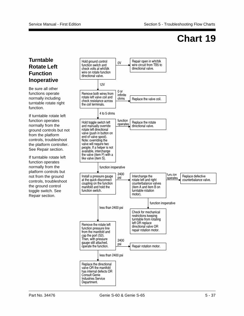
Part No. 34476 Genie S-60 & Genie S-65 5 - 37
Service Manual - First Edition Section 5 - Troubleshooting Flow Charts
Chart 19
TurntableRotate LeftFunctionInoperativeBe sure all otherfunctions operatenormally includingturntable rotate rightfunction.
If turntable rotate leftfunction operatesnormally from theground controls but notfrom the platformcontrols, troubleshootthe platform controller.See Repair section.
If turntable rotate leftfunction operatesnormally from theplatform controls butnot from the groundcontrols, troubleshootthe ground controltoggle switch. SeeRepair section.
#���������������������������� ���� ����������� �1���������������������������������������
�� ������������� �1�����������������2"'�������������������
���
��������� ������������������������������ �������������������� ���������������
����������� �� �������� �����������
8��'� ��
#�������������� �������������!���������������������������������3��� ������������������������4�>���?����������� ������������@��������������+� �������������������������� ����� ������3����74��� ����������3����,4�
��������������� �������� �������
�����������������
������������������
+����������������������� �@����:��������������������� ������������������ ���� ������������� �
�8����� +����� ����� �
��������������� ���������������������3����6�������"������������������������4�
L[TIZOUTUVKXGZKY
� �������� ������������������������������������������������)������������������������)���������������������
������������������
�����������������������������������
����� ���8�����
������� ��������������������������������� ��������������� �����3,�4�2 ������ ����������������������� ����������� ���������
�8�����
��������������������
����� ���8�����
�������� �����������������)�� �������� ����������������)��������*����+���������,������-����������
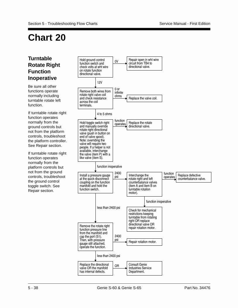
5 - 38 Genie S-60 & Genie S-65 Part No. 34476
Service Manual - First EditionSection 5 - Troubleshooting Flow Charts
Chart 20
TurntableRotate RightFunctionInoperativeBe sure all otherfunctions operatenormally includingturntable rotate leftfunction.
If turntable rotate rightfunction operatesnormally from theground controls butnot from the platformcontrols, troubleshootthe platform controller.See Repair section.
If turntable rotate rightfunction operatesnormally from theplatform controls butnot from the groundcontrols, troubleshootthe ground controltoggle switch. SeeRepair section.
#���������������������������� ���� ����������� �������������������������������������
�� ������������� ���������������2"8�������������������
���
��������� ����������������� �������������� �������������������� ���������������
����������� ��
�������� �����������
8��'� ��
#�������������� ��� �����������!����������������� �����������������3��� ������������������������4�>���?����������� ������������@��������������+� �������������������������� ����� ������3����74��� ����������3����,4�
��������������� �������� �������
�����������������
������������������
+����������������������� �@����:��������������������� ������������������ ���� ������������� �
�8����� +����� ����� �
��������� ���������������������������3����6�������"������������������������4�
��������������� ���������������
��������������������
������������������
� �������� ������������������������������������������������ �)������������������������)���������������������
����� ���8�����
������� ���������� ������������������������ ��������������� �����3,�4�2 ������ ����������������������� ����������� ���������
�8�����
��������������������
����� ���8�����
�������� �����������������)�� �������� �����������������
)� �������*����+���������,������-����������
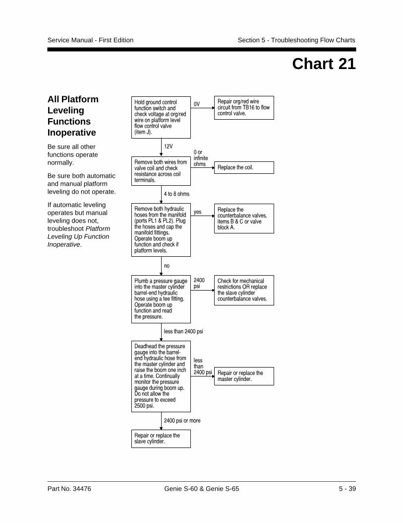
Part No. 34476 Genie S-60 & Genie S-65 5 - 39
Service Manual - First Edition Section 5 - Troubleshooting Flow Charts
Chart 21
All PlatformLevelingFunctionsInoperativeBe sure all otherfunctions operatenormally.
Be sure both automaticand manual platformleveling do not operate.
If automatic levelingoperates but manualleveling does not,troubleshoot PlatformLeveling Up FunctionInoperative.
��� ���� ����������� ����$ ���������$ ��0� ��76��D�76�1��7������� ������������������$ ���$������������� ����$���� �������������$���$ ���������
��� ����������� ����������������� �����!�D��� �������� ���@�
�
7��������������������� ��������������������/������������� ��������������$������������ ����$���� �������������������
�<�����
������$ ���������������� ����������������������������� ������������������
����������<������
.������������������������� ��������/�������������� ���$ ����������������������������� �� ����������������� ��������� �� ����������������������� �����. �� ���� ����������� ��&�����*�������
��������<������ ������ ����������
�������������
�<������� �� �
������ ������������������������
" ���� ����� � �$���� ������������������ ������� �)������ �����$ �������$� ��� � �������0����E1�
�� ������ �)������������$ ���!�'� �$� �� � ��������
���
��� ���� �������$ �������� ����������������������� ���� ����������
�� ��$���� ��� ������������ ���
<� �2� ���
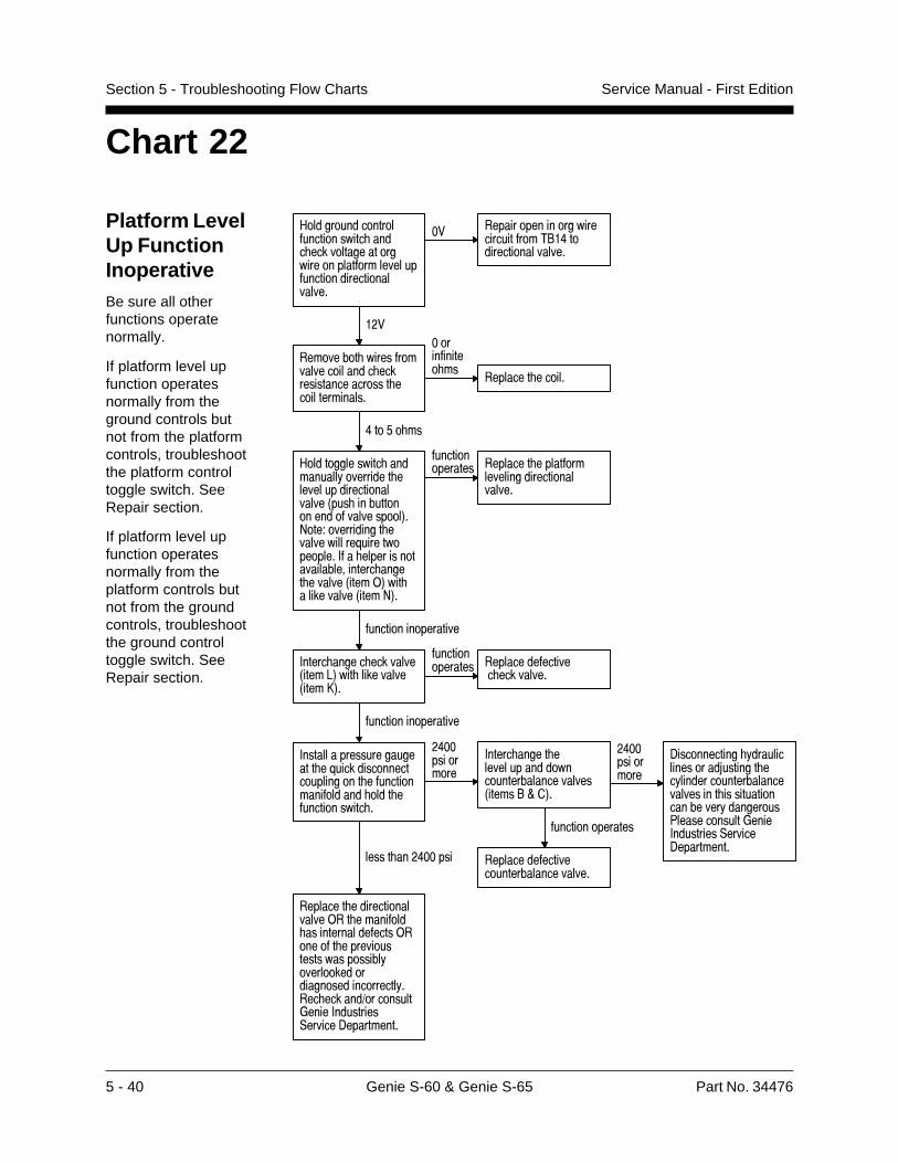
5 - 40 Genie S-60 & Genie S-65 Part No. 34476
Service Manual - First EditionSection 5 - Troubleshooting Flow Charts
Chart 22
Platform LevelUp FunctionInoperativeBe sure all otherfunctions operatenormally.
If platform level upfunction operatesnormally from theground controls butnot from the platformcontrols, troubleshootthe platform controltoggle switch. SeeRepair section.
If platform level upfunction operatesnormally from theplatform controls butnot from the groundcontrols, troubleshootthe ground controltoggle switch. SeeRepair section.
#���������������������������� ���� �����������������������������������������������������������
�� �����������������������������2"�8�������������������
���
��������� ��������������������� �������������������� ���������������
����������� ��
�������� ������
8��'� ��
#�������������� ����������!��������� ������������������������3��� ������������������������4�>���?����������� ������������@��������������+� �������������������������� ����� ������3����)4��� ����������3����>4�
��������������� �������� ��������
�������������������������
������������������
+����� ����� ��������3����<4��� ���������3����B4�
��������������� ���������������
� ���������
������������������
+����������������������� �@������������������������� ������������������ ���� ������������� �
�8�����������
+����� ����� �����������������������������������3�����"F�4�
�8�����������
-������������ !����������������5������� ��!����������������������������� �������������������!���������7������������*����+���������,������-����������
���������������
�����������������������������������
����� ���8�����
�������� �����������������)�� �������� ����������������)������ ������������������������!�������������������������������!���� ������1���������*����+���������,������-����������
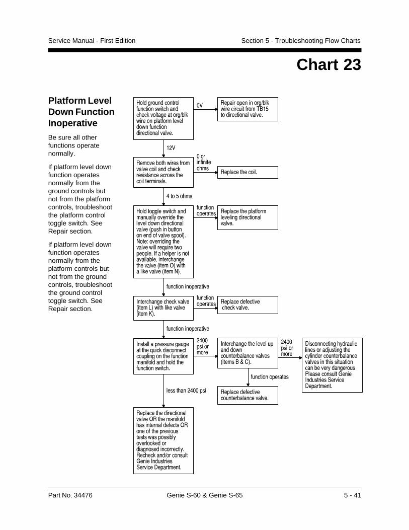
Part No. 34476 Genie S-60 & Genie S-65 5 - 41
Service Manual - First Edition Section 5 - Troubleshooting Flow Charts
Chart 23
Platform LevelDown FunctionInoperativeBe sure all otherfunctions operatenormally.
If platform level downfunction operatesnormally from theground controls butnot from the platformcontrols, troubleshootthe platform controltoggle switch. SeeRepair section.
If platform level downfunction operatesnormally from theplatform controls butnot from the groundcontrols, troubleshootthe ground controltoggle switch. SeeRepair section.
#���������������������������� ���� ���������������1�������������������������������������������������
�� ���������������1�����������������2"�'�������������������
���
��������� ��������������������� �������������������� ���������������
����������� ��
�������� ������
8��'� ��
#�������������� ����������!��������� ��������������������������3��� ������������������������4�>���?����������� ������������@��������������+� �������������������������� ����� ������3����)4��� ����������3����>4�
��������������� �������� ��������
�������������������������
������������������
+����� ����� ��������3����<4��� ���������3����B4�
��������������� ���������������
� ���������
������������������
+����������������������� �@������������������������� ������������������ ���� ������������� �
�8�����������
+����� ����� �����������������������������������3�����"F�4�
�8�����������
-������������ !����������������5������� ��!����������������������������� �������������������!���������7������������*����+���������,������-����������
���������������
�����������������������������������
����� ���8�����
�������� �����������������)�� �������� ����������������)������ ������������������������!�������������������������������!���� ������1���������*����+���������,������-����������
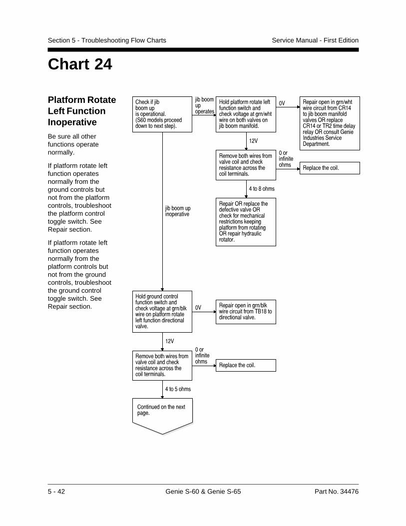
5 - 42 Genie S-60 & Genie S-65 Part No. 34476
Service Manual - First EditionSection 5 - Troubleshooting Flow Charts
Chart 24
Platform RotateLeft FunctionInoperativeBe sure all otherfunctions operatenormally.
If platform rotate leftfunction operatesnormally from theground controls butnot from the platformcontrols, troubleshootthe platform controltoggle switch. SeeRepair section.
If platform rotate leftfunction operatesnormally from theplatform controls butnot from the groundcontrols, troubleshootthe ground controltoggle switch. SeeRepair section.
� ����5����������������������3,&����������������������.�����4�
5����������������
#������������������������������� ���� ���������������1� ���������� ��������5��������������
�� ���������������1� ������������������8��5�������������������)�����������8��2����������!����!)��������*����+���������,������-�������������
��������� ��������������������� �������������������� ���������������
����������� �� �������� ������
8��$� ��
������)��������� ��������������)�� �������� �������������������������������������������)������� !���������������
5�������������������
#���������������������������� ���� ���������������1�������������������������������������������������
�� ���������������1�����������������2"�$�������������������
���
��������� ��������������������� �������������������� ���������������
����������� ��
�������� ������
8��'� ��
������������ ���.������
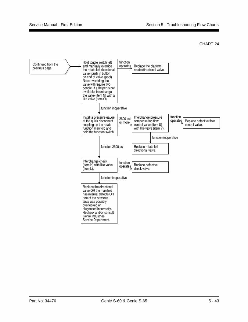
Part No. 34476 Genie S-60 & Genie S-65 5 - 43
Service Manual - First Edition Section 5 - Troubleshooting Flow Charts
CHART 24
������������� ��������������
#�������������� �������������!��������� ��������������������������3��� ������������������������4�>���?����������� ������������@��������������+� �������������������������� ����� ������3����>4��� ����������3����)4�
��������������� �������� ��������
�����������������������
������������������
+����������������������� �@������������������������� ������������������������ ���� ������������� �
�&�����������
+����� ���������������������������������������3����G4��� ���������3�����4�
��������������� ������������������
�������������
������������������
���������������������������������
��������&�����
+����� ����� ���3����#4��� ���������3����<4�
��������������� ���������������
� ���������
������������������
�������� �����������������)�� �������� ����������������)������ ������������������������!�������������������������������!���� ������1���������*����+���������,������-����������
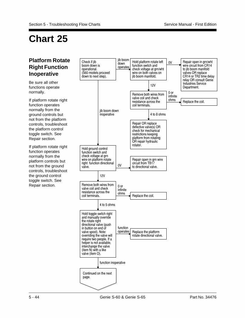
5 - 44 Genie S-60 & Genie S-65 Part No. 34476
Service Manual - First EditionSection 5 - Troubleshooting Flow Charts
Chart 25
Platform RotateRight FunctionInoperativeBe sure all otherfunctions operatenormally.
If platform rotate rightfunction operatesnormally from theground controls butnot from the platformcontrols, troubleshootthe platform controltoggle switch. SeeRepair section.
If platform rotate rightfunction operatesnormally from theplatform controls butnot from the groundcontrols, troubleshootthe ground controltoggle switch. SeeRepair section.
� �������8������������������������2,7)�����������������������!������3�
8�����������������
������������������������������2�3���� ���������� ��������������������������������������������������� �������������
8���������������������
������������������������������ ����� �������������������������������������� ���������������������������� )�
������������������������������$%�0��������������������
�&�
���������� ������������������������ �������������������� ���������������
)����������� ��
��������� �������
'����/�� ��
���������������� ��� ��������������������� ���������� ������������������2��� ������������������������������3��9���:���������� ������������;���������������+��� ���������������������#����� ������ �������2�����93��� �������������2������3�
��������������� ��������� ���������
�����������������������
�������������������
�������������� ����!������
������������������������������������ ����� ����������������� ���������� ����������8�����������������
)� ���������������� ������������������'���8�����������������������������������'���$�&���������������������������*����+���������,�����-����������&�
���������� ������������������������ �������������������� ���������������
)����������� �� ��������� �������
'����5�� ��
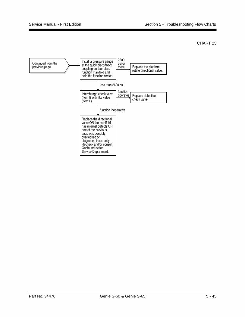
Part No. 34476 Genie S-60 & Genie S-65 5 - 45
Service Manual - First Edition Section 5 - Troubleshooting Flow Charts
CHART 25
������������� ��������������
+����������������������� �@������������������������� ������������������������ ���� ������������� �
�&����������� �������� ��������
�����������������������
����� ���&�����
+����� ����� ��������3����+4��� ���������3����<4�
��������������� ���������������
� ���������
������������������
�������� �����������������)�� �������� ����������������)������ ������������������������!�������������������������������!���� ������1���������*����+���������,������-����������
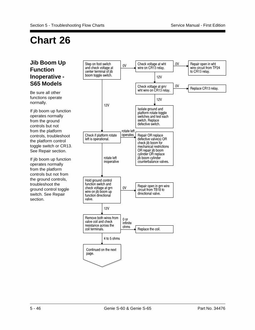
5 - 46 Genie S-60 & Genie S-65 Part No. 34476
Service Manual - First EditionSection 5 - Troubleshooting Flow Charts
Jib Boom UpFunctionInoperative -S65 ModelsBe sure all otherfunctions operatenormally.
If jib boom up functionoperates normallyfrom the groundcontrols but notfrom the platformcontrols, troubleshootthe platform controltoggle switch or CR13.See Repair section.
If jib boom up functionoperates normallyfrom the platformcontrols but not fromthe ground controls,troubleshoot theground control toggleswitch. See Repairsection.
Chart 26
,������������� ���� ���������������������������5����������������� �
�� � ������������� ���������� ����!�
�� ������������� ���������������27�8����� ����!�
���
� ���������������1� ���������� ����!�
������������ ����!�
���
+��������������������������������������� ������������ ����� ��������������������� �
���
� ����������������������������������
����������������� ������)��������
�������������3�4)�� ���5����������� ������������������)�������5�������!������)��������5�������!���������������������������
��������������������
#���������������������������� ���� ���������������������5��������������������������������
�� �����������������������������2"�$�������������������
���
��������� ��������������������� �������������������� ���������������
����������� ��
�������� ������
8��'� ��
������������ ���.������

Part No. 34476 Genie S-60 & Genie S-65 5 - 47
Service Manual - First Edition Section 5 - Troubleshooting Flow Charts
CHART 26
������������� ��������������
#�������������� ����������!��������� �5������������������������3��� ������������������������4�>���?����������� ������������@��������������+� �������������������������� ����� ������3����>4��� ����������3����)4�
��������������� �������� �5��������
�����������������
������������������
+����������������������� �@������������������������� ������������������ ���� ������������� �
�&�����������
+����� ���������������������������������������3����G4��� ���������3�����4�
��������������� ������������������
�������������
������������������
�������5�����������������������
����� ���&�����
+����� ����� ���3����#4��� ���������3����<4�
��������������� ���������������
� ���������
������������������
�������� �����������������)�� �������� ����������������)������ ������������������������!�������������������������������!���� ������1���������*����+���������,������-����������
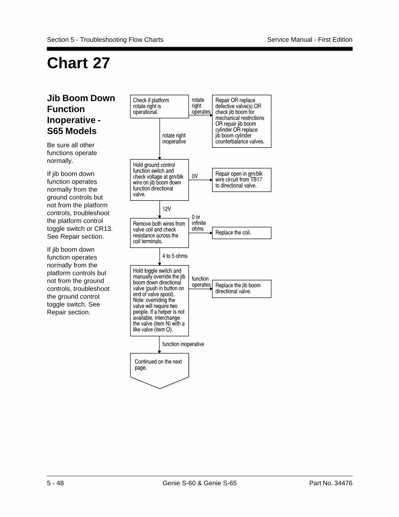
5 - 48 Genie S-60 & Genie S-65 Part No. 34476
Service Manual - First EditionSection 5 - Troubleshooting Flow Charts
Jib Boom DownFunctionInoperative -S65 ModelsBe sure all otherfunctions operatenormally.
If jib boom downfunction operatesnormally from theground controls butnot from the platformcontrols, troubleshootthe platform controltoggle switch or CR13.See Repair section.
If jib boom downfunction operatesnormally from theplatform controls butnot from the groundcontrols, troubleshootthe ground controltoggle switch. SeeRepair section.
Chart 27
� �������������������� ���������������
��������� ���������
������)���������������������3�4)�� ���5����������� ������������������)�������5�������!������)��������5�������!���������������������������
��������� ������������
#���������������������������� ���� ���������������1���������5����������������������������������
�� ���������������1�����������������2"�%�������������������
���
��������� ��������������������� �������������������� ���������������
����������� ��
�������� ������
8��'� ��
#�������������� ����������!��������� �5��������������������������3��� ������������������������4�>���?����������� ������������@��������������+� �������������������������� ����� ������3����>4��� ����������3����)4�
��������������� �������� �5������
�����������������
������������������
������������ ���.������

Part No. 34476 Genie S-60 & Genie S-65 5 - 49
Service Manual - First Edition Section 5 - Troubleshooting Flow Charts
CHART 27
������������� ��������������
+����������������������� �@������������������������� ������������������������ ���� ������������� �
�&����������� �������� �5������
�����������������
����� ���&�����
+����� ����� ���3����+4��� ���������3����<4�
��������������� ���������������
� ���������
������������������
�������� �����������������)�� �������� ����������������)������ ������������������������!�������������������������������!���� ������1���������*����+���������,������-����������
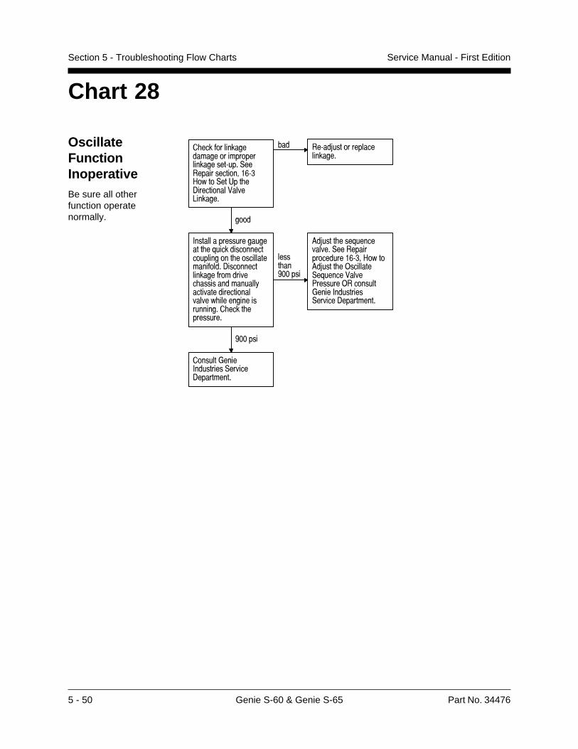
5 - 50 Genie S-60 & Genie S-65 Part No. 34476
Service Manual - First EditionSection 5 - Troubleshooting Flow Charts
Chart 28
OscillateFunctionInoperativeBe sure all otherfunction operatenormally.
������������ ��� � �������������� ����������������� �������������������������������� ������� �! "�#��� ���
$ � ��� �%�������� ����� ���
����
&��� � ��������� ��� ������'���������������������������������� ��� ������� ������������ ���������"��� ����� ���� �� ( ���" ����������� " "����������������������������������������
����� �)**����
+�%����������'�����" "���������� ���������������������+�%��������,��� ����'������! "�-������,��������.�����&����������"���� �� ������
)**����
�������.����&�����������"��� �� ������
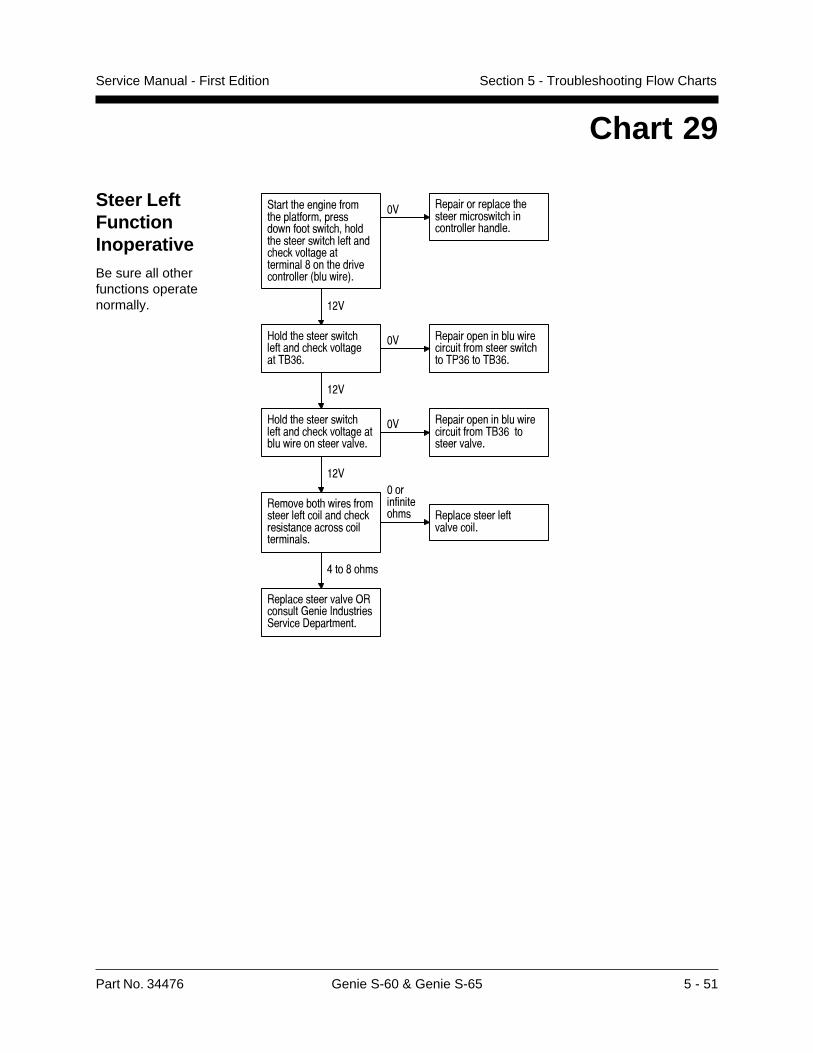
Part No. 34476 Genie S-60 & Genie S-65 5 - 51
Service Manual - First Edition Section 5 - Troubleshooting Flow Charts
Chart 29
Steer LeftFunctionInoperativeBe sure all otherfunctions operatenormally.
,����� ����������� �������������������������� � ���� ����������� ������� ��������������������$��� ����������������3�������4�
�� ���������������� ���������������� ������������ ������
���
#���� ����������� ������� ������������2" &�
�� ��������������������������������������� ��27 &��2" &�
���
#���� ����������� ������� ��������������������������������
�� �����������������������������2" &�������������
���
��������� ������������������������ ���������������������������������
����������� �� ���������������
����������
8��$� ��
�����������������)��������*����+���������,������-����������
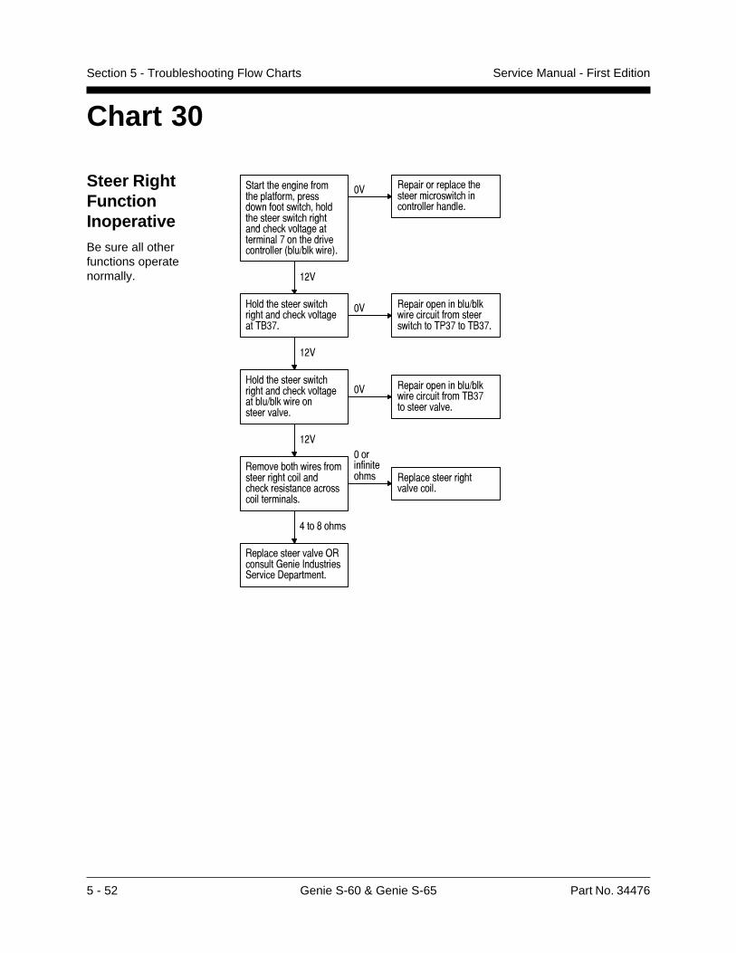
5 - 52 Genie S-60 & Genie S-65 Part No. 34476
Service Manual - First EditionSection 5 - Troubleshooting Flow Charts
Chart 30
Steer RightFunctionInoperativeBe sure all otherfunctions operatenormally.
,����� ����������� �������������������������� � ���� ����������� ��� ����� ��������������������%��� ����������������3���1�������4�
�� ���������������� ���������������� ������������ ������
���
#���� ����������� ��� ����� ������������2" %�
�� ���������������1��������������������������� ��27 %��2" %�
���
#���� ����������� ��� ����� ���������������1��������������������
�� ���������������1�����������������2" %�������������
���
��������� ���������������� ��������� ���������������������������������
����������� �� ��������������� �
����������
8��$� ��
�����������������)��������*����+���������,������-����������
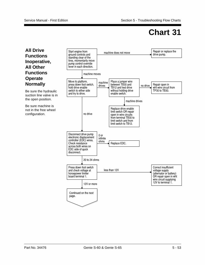
Part No. 34476 Genie S-60 & Genie S-65 5 - 53
Service Manual - First Edition Section 5 - Troubleshooting Flow Charts
All DriveFunctionsInoperative,All OtherFunctionsOperateNormallyBe sure the hydraulicsuction line valve is inthe open position.
Be sure machine isnot in the free wheelconfiguration.
Chart 31
,��������������������������������������������� �����������������!��������������������������������� ����������
��� �������������� ���������������� �����������
��� ��������
=������������������������������ � ������������������� ����� �����������!��������
��� ���������
7�����5����������������2" ����2"����������������� ��� ���������������������� �
������� ������������� ���������������27 ���2" ��
��� ���������
���������������������������� )������������������������������������2" ������������� ���������������� ��2"���
�������
-��������������������������������������������������3A-�4������� ���������������������� �������A-������@���������������
����������� ��
�������A-��
�����8� ��
7���������������� ���� ������������ �������������������������������
����� ����������������������������������!3������������������!4)�������������� �����������������!���������������������������
������������ ���.������
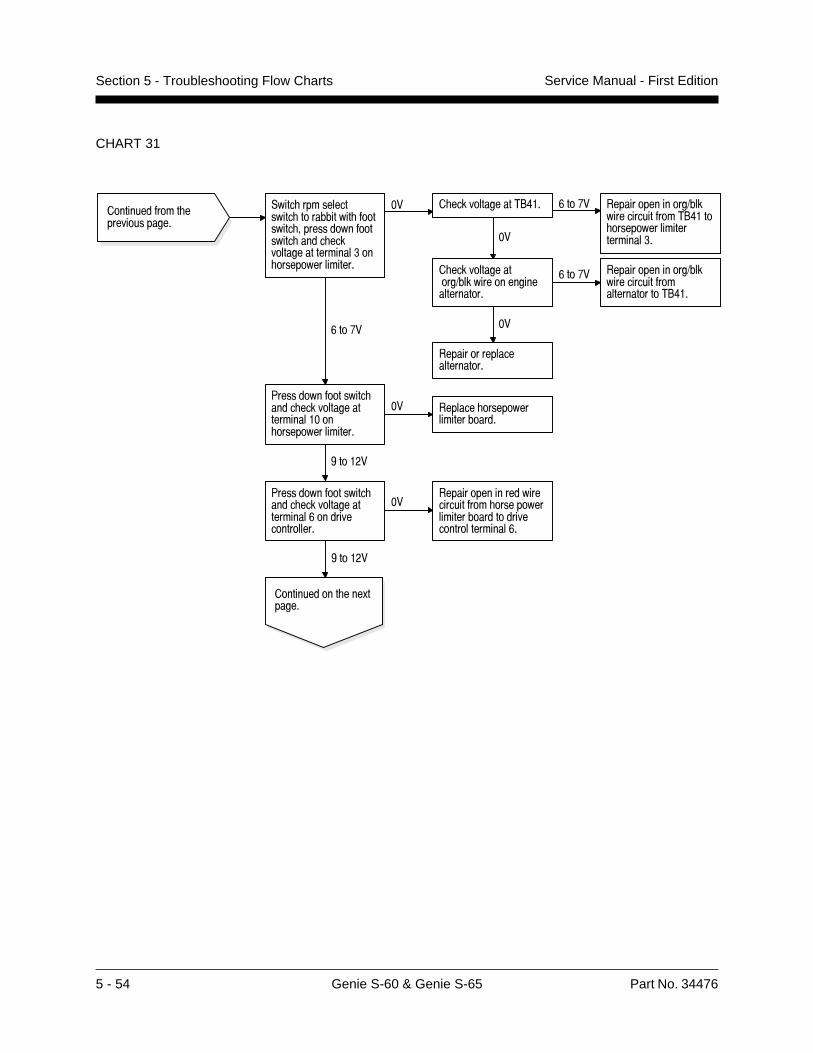
5 - 54 Genie S-60 & Genie S-65 Part No. 34476
Service Manual - First EditionSection 5 - Troubleshooting Flow Charts
CHART 31
������������� ��������������
,���� �������������� ����������� �������� ������������������ ���� �������������������� �� �����������������
�� � ������������2"8�� &��%� ���������������1�����������������2"8��� ������������������������ ���
� ���������������1��������������������������
&��%� ���������������1�����������������������������2"8��
��
��������������������������
&��%�
7���������������� ���� ������������������������ �����������������
�� ������� ����������������������
(�����
7���������������� ���� ��������������������&������������������
������������������������������� �������������������������������������������&�
(�����
������������ ���.������

Part No. 34476 Genie S-60 & Genie S-65 5 - 55
Service Manual - First Edition Section 5 - Troubleshooting Flow Charts
CHART 31
������������� ��������������
-������������������A-������������������������ � ����������������������������������������� �������������������������8���'������������������
�� �������������������������������
8��%�
7���������������� � ����������������������������������������� �������������������������27 ����27 ��
����������������� ��� ���� �1����������������������������������27 ����27 ������������!�
8��%�
7���������������� � ����������������������������������������� �������������������������2" ����2" ��
�� ��������������� ��� ���� �1�����������������2" ����2" ������������!�
8��%�
7���������������� � ����������������������������������������� ����������������� �����������A-�@���������������
��
������������� �1�����������������2" ���A-�@��������������)�������������� ���������������2" ���A-�@���������������
8��%�
����������������A-�)��������*����+���������,������-����������
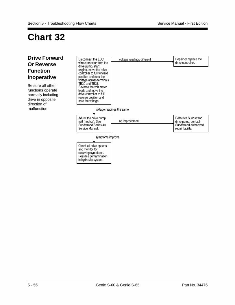
5 - 56 Genie S-60 & Genie S-65 Part No. 34476
Service Manual - First EditionSection 5 - Troubleshooting Flow Charts
Chart 32
Drive ForwardOr ReverseFunctionInoperativeBe sure all otherfunctions operatenormally includingdrive in oppositedirection ofmalfunction.
-���������� �A-������������������ ���������������������������� ������������������������������������������� �����������������������2" ����2" ���������� ����������������������� �������������������������������������������� ���������
���������������������� ���������������� �����������������
���������������� �����
6�5���� ��������������3�������4�,��,���������,�����8�,������=������
�������������-�������,��������������������������,������������ ���;��������������!�
�!�������������
� ���������������������������������������!�������7���������������������� !��������!�����
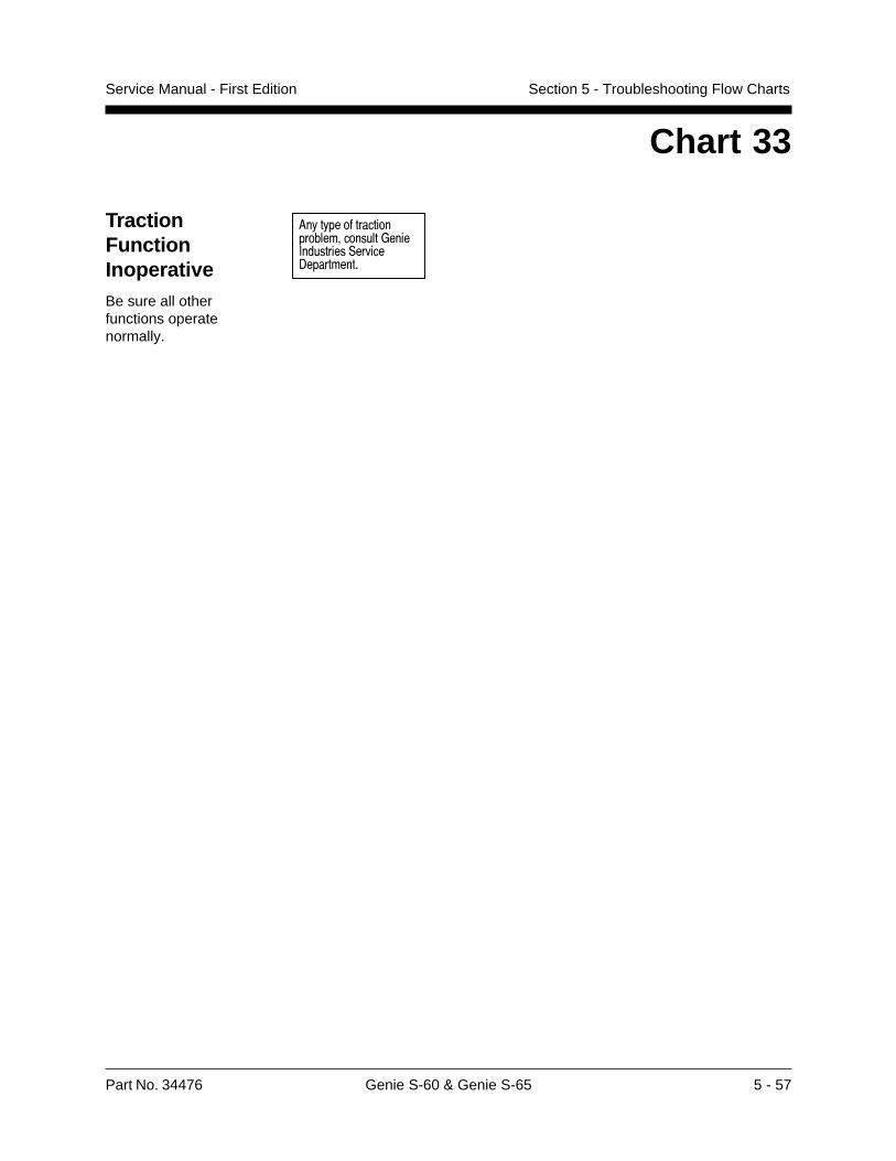
Part No. 34476 Genie S-60 & Genie S-65 5 - 57
Service Manual - First Edition Section 5 - Troubleshooting Flow Charts
Chart 33
TractionFunctionInoperativeBe sure all otherfunctions operatenormally.
��������������� ��������������������� ������� ������ ������������
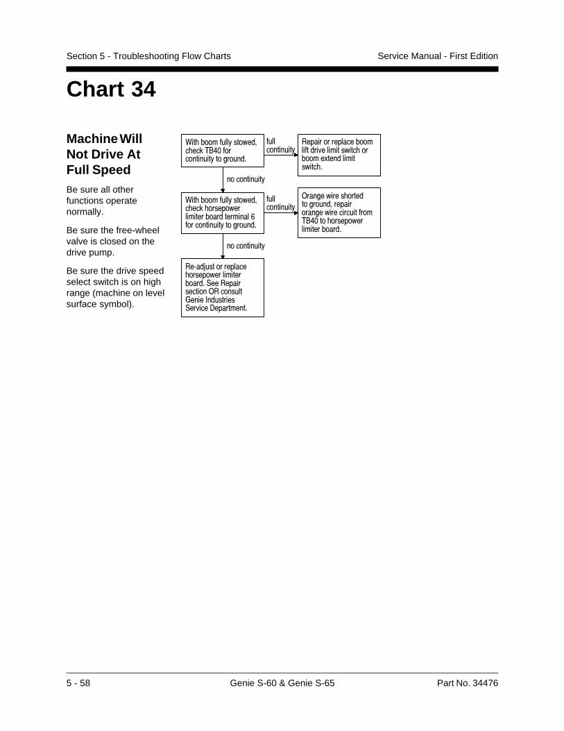
5 - 58 Genie S-60 & Genie S-65 Part No. 34476
Service Manual - First EditionSection 5 - Troubleshooting Flow Charts
Chart 34
Machine WillNot Drive AtFull SpeedBe sure all otherfunctions operatenormally.
Be sure the free-wheelvalve is closed on thedrive pump.
Be sure the drive speedselect switch is on highrange (machine on levelsurface symbol).
1�� �����������������#� ����$%')�����������������������
��������������
��������������������������������������� ��������!�������������� �
�������������
1�� �����������������#� ���� ��������������������������7�����������������������
��������������
���������� ������������#������������������������$%')���� ������������������
�������������
�����8������������ �������������������,��������������������������*�����+��������,������-���������
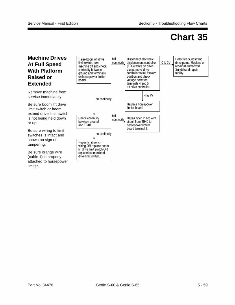
Part No. 34476 Genie S-60 & Genie S-65 5 - 59
Service Manual - First Edition Section 5 - Troubleshooting Flow Charts
Chart 35
Machine DrivesAt Full SpeedWith PlatformRaised orExtendedRemove machine fromservice immediately.
Be sure boom lift drivelimit switch or boomextend drive limit switchis not being held downor up.
Be sure wiring to limitswitches is intact andshows no sign oftampering.
Be sure orange wire(cable 1) is properlyattached to horsepowerlimiter.
����������������������������� #������� ������������� ��������������������������������������7��� ������������������
��������������
-����������������������������������������2<-�3����������������#��������������������������������������������� ��������������������������'�����/�����������������
)����4�-���������,��������������������������������������� ��=��,����������������������
'����0�
�������� ������������������
�������������
� ������������������������������$%')�
�������������� �������������������
�����������$%')��� ��������������������������7�
�������������
���������������� ��������������������������������������� ����������������!������������������� �
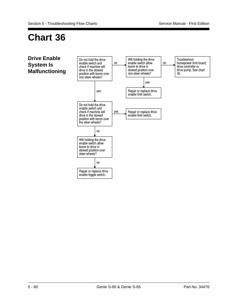
5 - 60 Genie S-60 & Genie S-65 Part No. 34476
Service Manual - First EditionSection 5 - Troubleshooting Flow Charts
Chart 36
Drive EnableSystem IsMalfunctioning
-���� ���� ����������������� ���� ������� ��������������� ������������������ �����������:������ ����9
��0��� ������� ����������������� ���������������������������������������:������ ����9
��2������� ��� �����������������������������������������������,��� ��� ��
!��
������������������������������������ �
!��
-���� ���� ����������������� ���� ������� ��������������� ������������������ ��������� ������� ����9
!�� ������������������������������������ �
��
0��� ������� ����������������� ������������������������������������������ ����9
��
������������������������������������� �
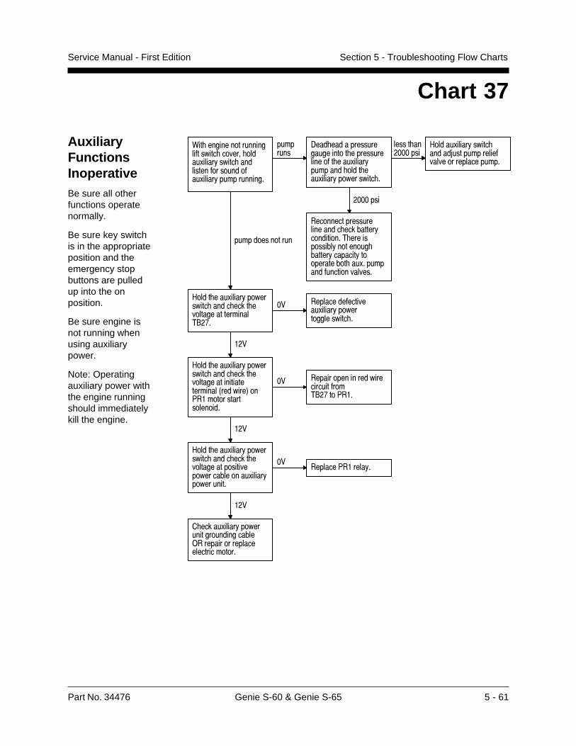
Part No. 34476 Genie S-60 & Genie S-65 5 - 61
Service Manual - First Edition Section 5 - Troubleshooting Flow Charts
Chart 37
AuxiliaryFunctionsInoperativeBe sure all otherfunctions operatenormally.
Be sure key switchis in the appropriateposition and theemergency stopbuttons are pulledup into the onposition.
Be sure engine isnot running whenusing auxiliarypower.
Note: Operatingauxiliary power withthe engine runningshould immediatelykill the engine.
0�� ������������������������ ������ �����.�����!����� �������������������.�����!������������
��������
-��� ���������������������� ��������������� ���.�����!������� ���� ���.�����!���������� �
����� ���������
#�����.�����!����� �����5�������������������������������
�������
������������������������� ���������!����������2 ������������!�������� ������!�������!������������ ��.����������������������
��������������
#���� ���.�����!���������� ���� ���� ������������������2"�%�
�� �����������������.�����!���������������� �
���
#���� ���.�����!���������� ���� ���� ��������������������������3�������4��7���������������������
�� �����������������������������2"�%��7���
���
#���� ���.�����!���������� ���� ���� ��������������������������������.�����!����������
���������7������!�
���
� �����.�����!�����������������������)������������������������������
5 - 62 Genie S-60 & Genie S-65 Part No. 34476
Service Manual - First EditionSection 5 - Troubleshooting Flow Charts
This page intentionally left blank.
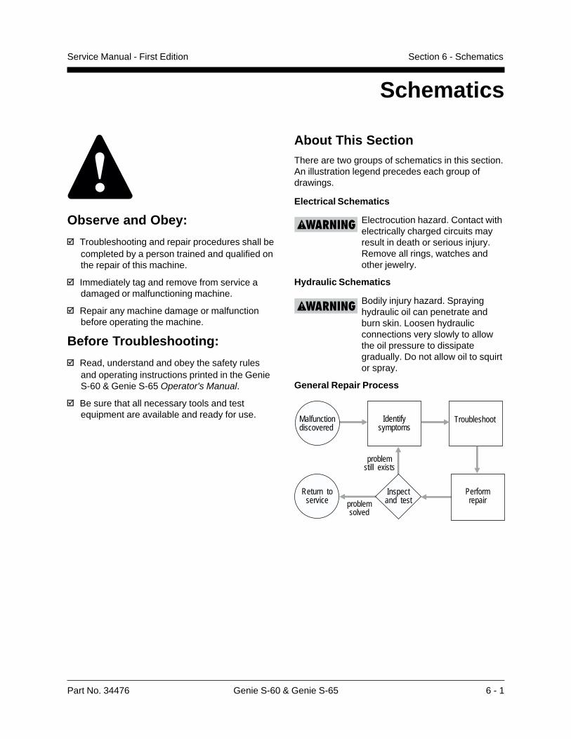
Schematics
Observe and Obey:
Troubleshooting and repair procedures shall becompleted by a person trained and qualified onthe repair of this machine.
Immediately tag and remove from service adamaged or malfunctioning machine.
Repair any machine damage or malfunctionbefore operating the machine.
Before Troubleshooting:
Read, understand and obey the safety rulesand operating instructions printed in the GenieS-60 & Genie S-65 Operator's Manual.
Be sure that all necessary tools and testequipment are available and ready for use.
About This SectionThere are two groups of schematics in this section.An illustration legend precedes each group ofdrawings.
Electrical Schematics
Electrocution hazard. Contact withelectrically charged circuits mayresult in death or serious injury.Remove all rings, watches andother jewelry.
Hydraulic Schematics
Bodily injury hazard. Sprayinghydraulic oil can penetrate andburn skin. Loosen hydraulicconnections very slowly to allowthe oil pressure to dissipategradually. Do not allow oil to squirtor spray.
General Repair Process
Malfunctiondiscovered
Identifysymptoms
Troubleshoot
Performrepair
Return toservice problem
solved
problemstill exists
Inspectand test
Part No. 34476 Genie S-60 & Genie S-65 6 - 1
Service Manual - First Edition Section 6 - Schematics
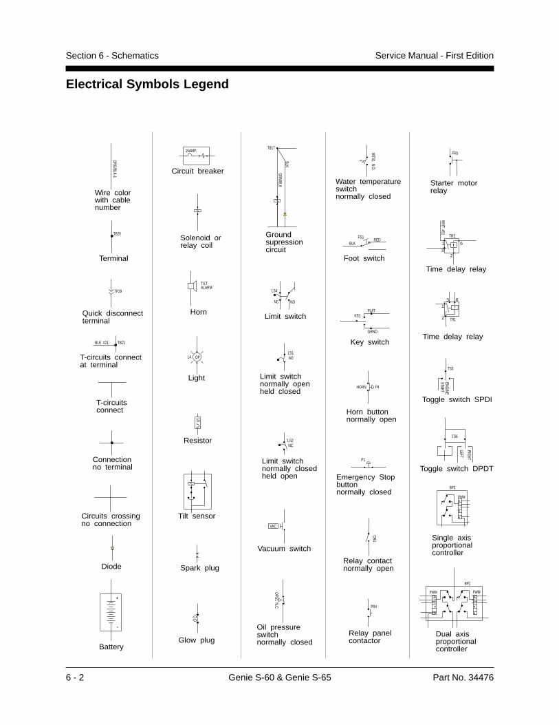
Service Manual - First EditionSection 6 - Schematics
6 - 2 Genie S-60 & Genie S-65 Part No. 34476
Electrical Symbols Legend
+
-
ORG/BLK-1
15AMP.
TB20
P1
KS1
GRND
PLAT
PR4
ALARMTILT
NOLS1
NCLS2
HORN P4
T
WHT #51
TR2
OPS1 N.C.
L4 OP
WTS1 N.O.
TP29
VAC
REDBLK
FS1
CR4
TS3
STARTENGINE
TS6
RIGHT
LEFT
BLK
GRN/BLK
TB17
PWMA
+
-
X
R R
X
-
+
A
PWM
BP1
10
R
X
-
+
A
PWM
BP2
BLK #21 TB21
NONC
LS4
TR1
PR5
1
2
3 6
1
23
6
Battery
Wire colorwith cable number
Circuit breaker
Connectionno terminal
Spark plug
Terminal
Emergency Stop buttonnormally closed
Key switch
Relay panelcontactor
Solenoid or relay coil
Horn
Tilt sensor
Limit switchnormally closedheld open
Limit switchnormally openheld closed
Horn buttonnormally open
T-circuits connect
Time delay relay
Oil pressure switchnormally closed
Light
Water temperature switchnormally closed
Quick disconnectterminal
Diode
Vacuum switch
Foot switch
Relay contactnormally open
Toggle switch SPDI
Circuits crossingno connection
Toggle switch DPDT
Groundsupressioncircuit
Starter motorrelay
Glow plug
Limit switch
T-circuits connect at terminal
Single axisproportional controller
Resistor
Dual axisproportional controller
T
Time delay relay
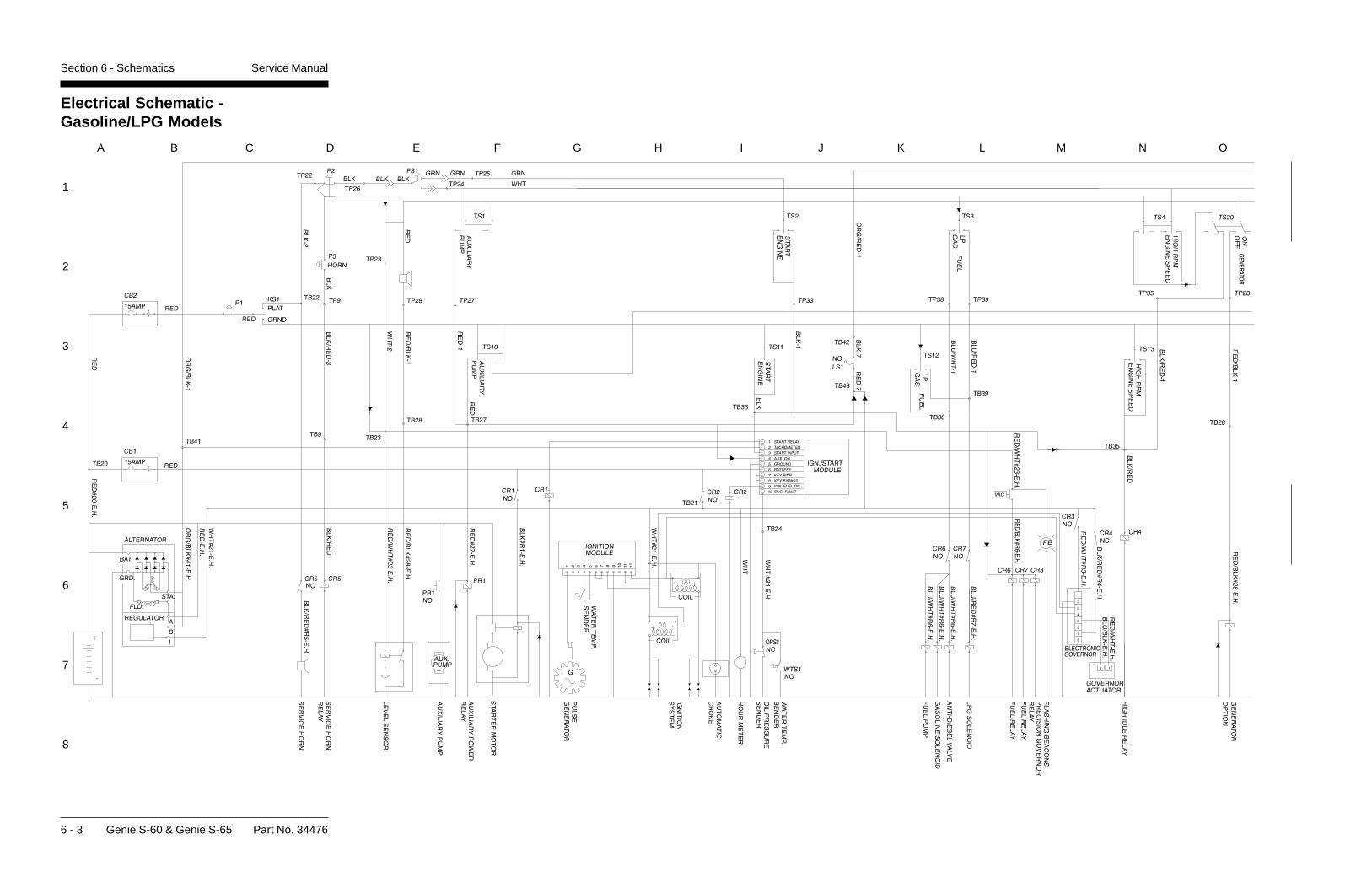
6 - 3 Genie S-60 & Genie S-65 Part No. 34476
Electrical Schematic -Gasoline/LPG Models
Section 6 - Schematics Service Manual
1
2
3
4
5
6
7
8
A B C D E F G H I J K L M N O
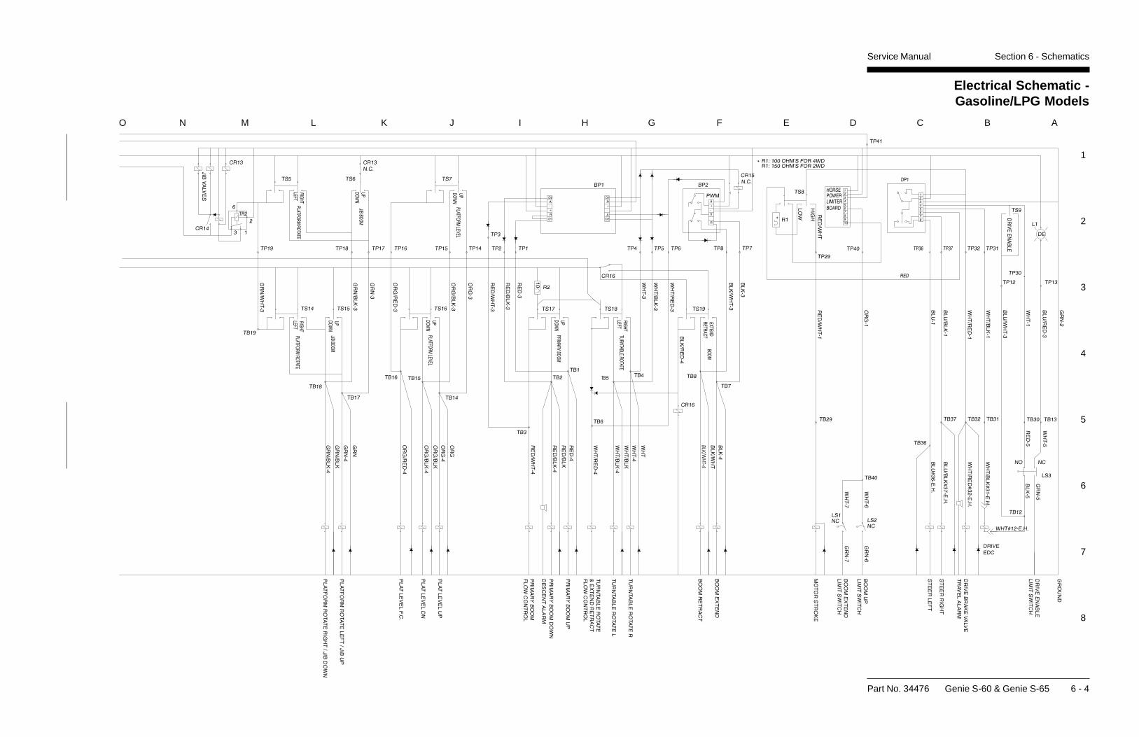
Part No. 34476 Genie S-60 & Genie S-65 6 - 4
Electrical Schematic -Gasoline/LPG Models
Service Manual Section 6 - Schematics
1
2
3
4
5
6
7
8
O N M L K J I H G F E D C B A
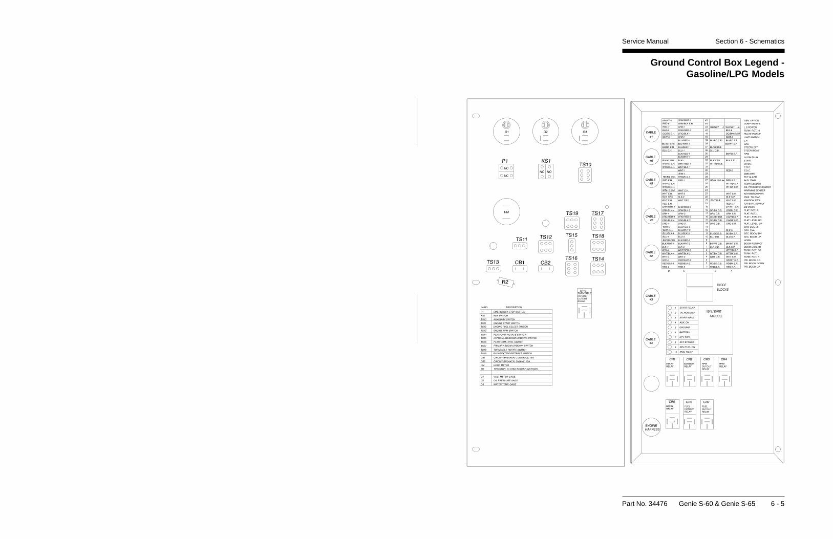
Part No. 34476 Genie S-60 & Genie S-65 6 - 5
Service Manual Section 6 - Schematics
Ground Control Box Legend -Gasoline/LPG Models
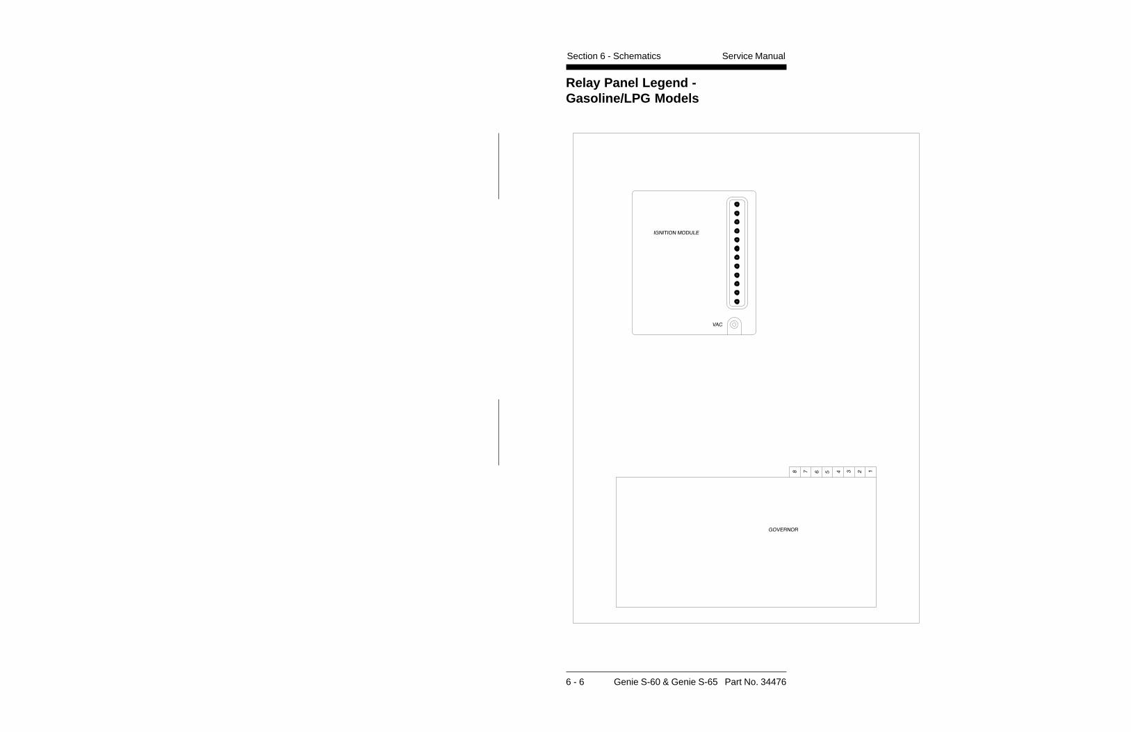
6 - 6 Genie S-60 & Genie S-65 Part No. 34476
Relay Panel Legend -Gasoline/LPG Models
Service ManualSection 6 - Schematics
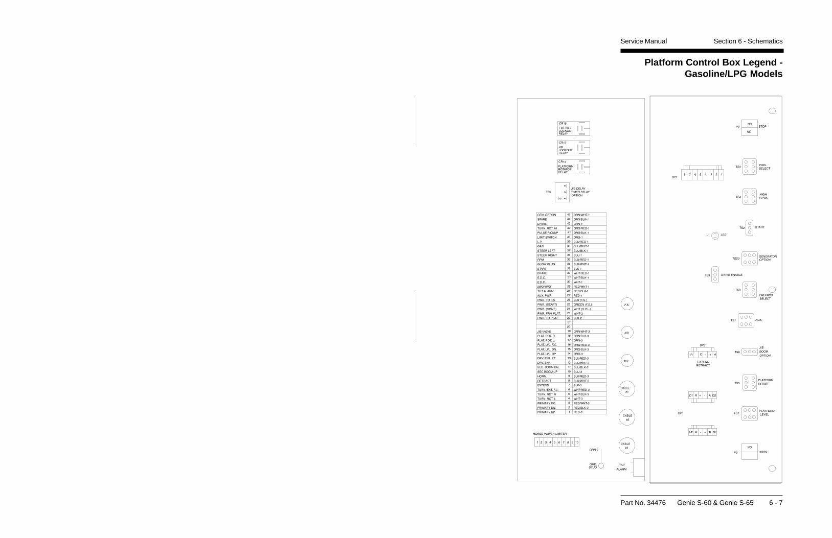
Part No. 34476 Genie S-60 & Genie S-65 6 - 7
Section 6 - SchematicsService Manual
Platform Control Box Legend -Gasoline/LPG Models
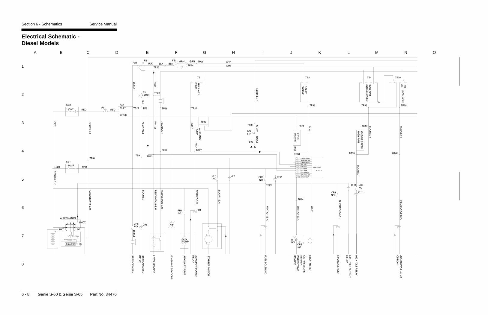
6 - 8 Genie S-60 & Genie S-65 Part No. 34476
Section 6 - Schematics Service Manual
Electrical Schematic -Diesel Models
1
2
3
4
5
6
7
8
A B C D E F G H I J K L M N O
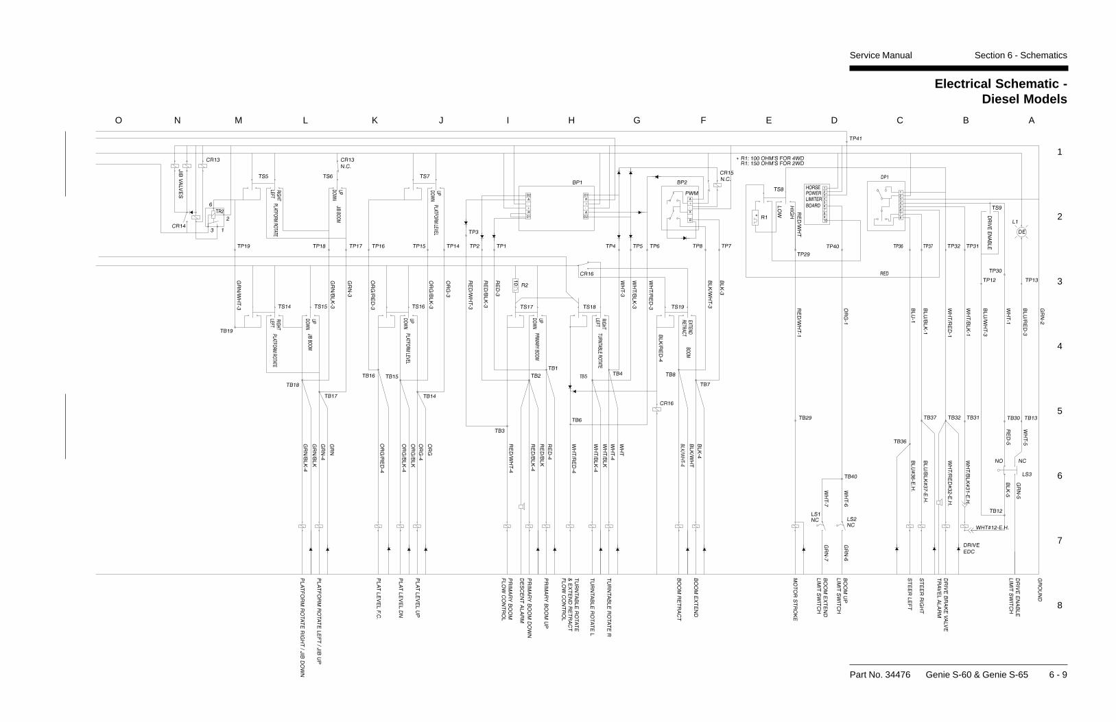
Electrical Schematic -Diesel Models
Part No. 34476 Genie S-60 & Genie S-65 6 - 9
Section 6 - SchematicsService Manual
1
2
3
4
5
6
7
8
O N M L K J I H G F E D C B A
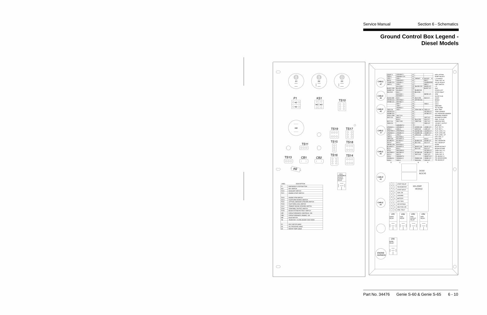
Part No. 34476 Genie S-60 & Genie S-65 6 - 10
Section 6 - SchematicsService Manual
Ground Control Box Legend -Diesel Models
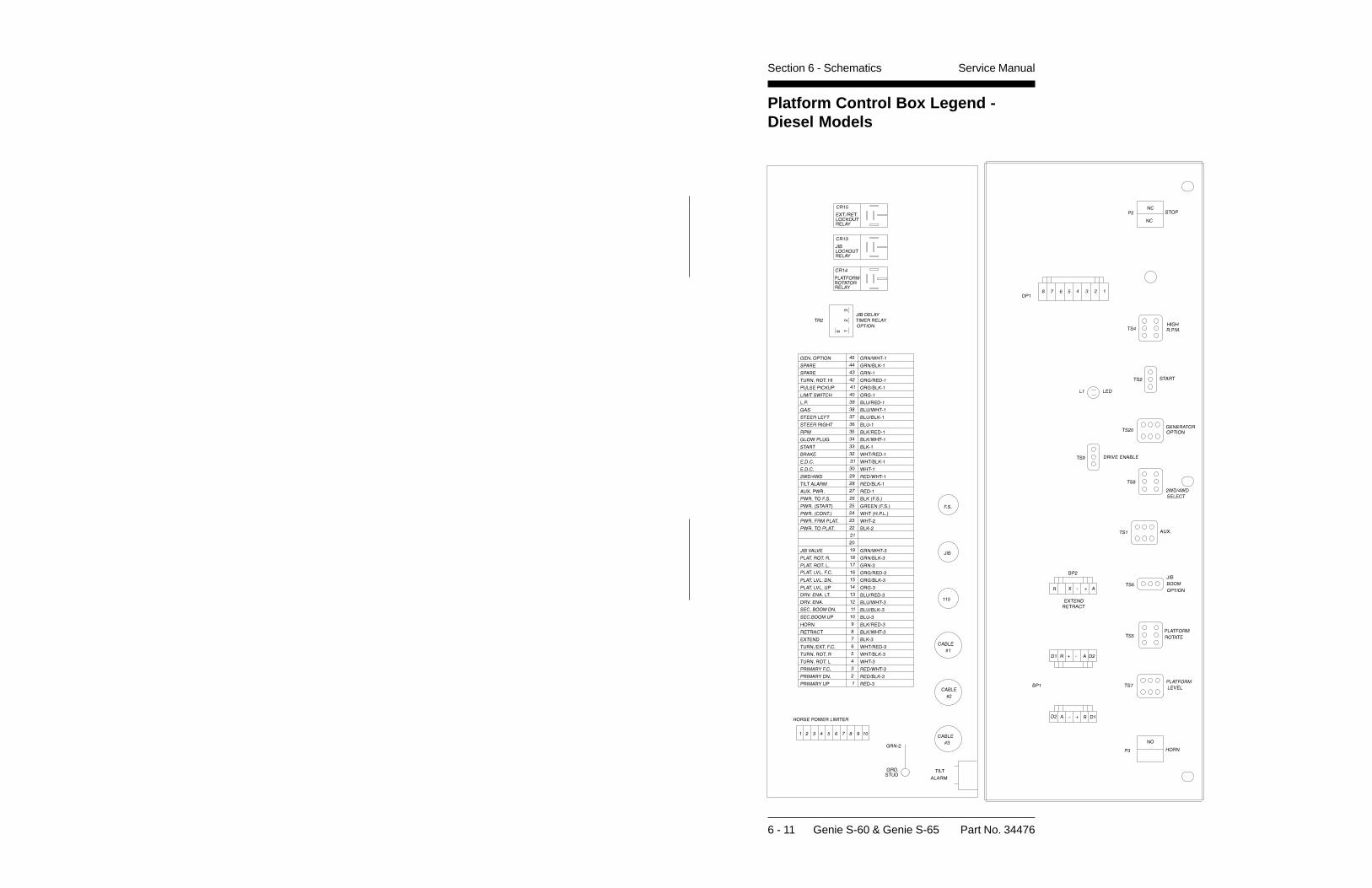
6 - 11 Genie S-60 & Genie S-65 Part No. 34476
Section 6 - Schematics Service Manual
Platform Control Box Legend -Diesel Models
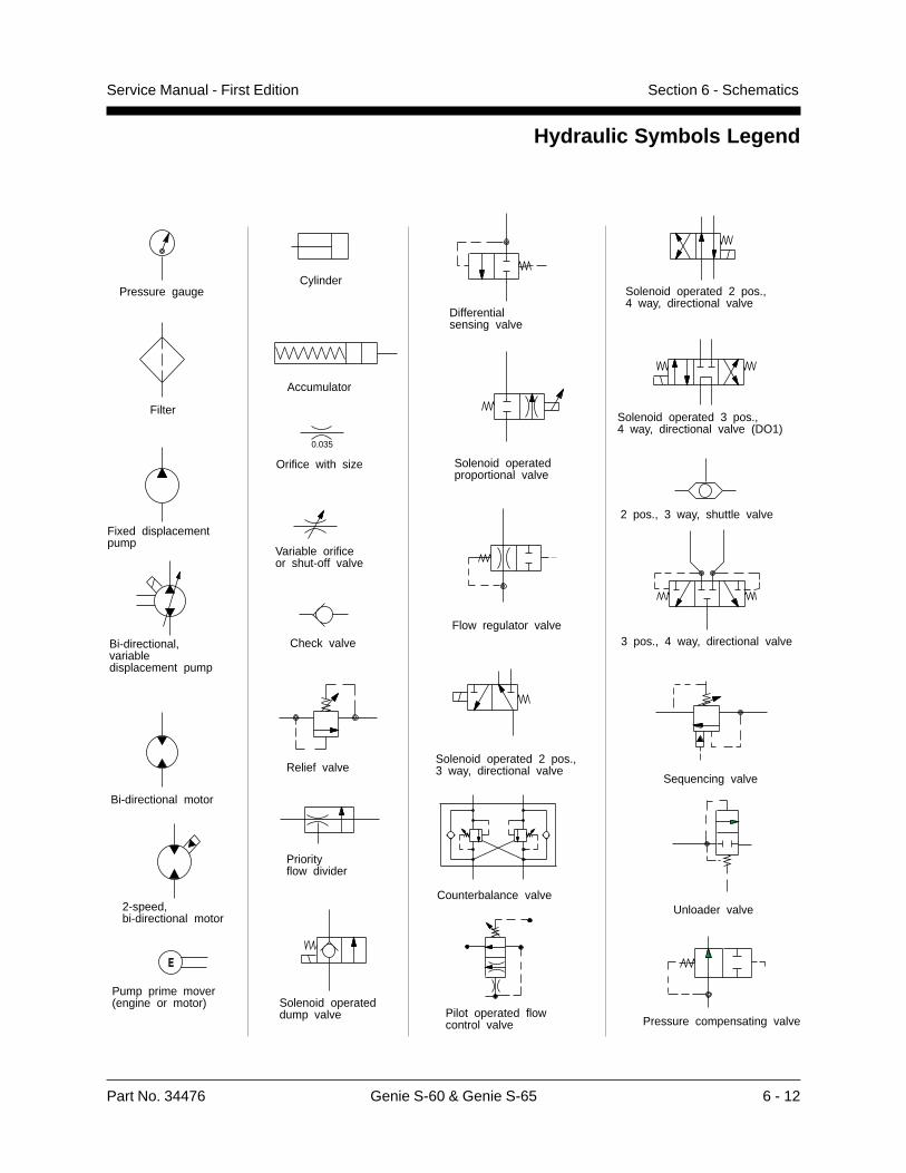
Part No. 34476 Genie S-60 & Genie S-65 6 - 12
Service Manual - First Edition Section 6 - Schematics
Hydraulic Symbols Legend
E
Pressure gauge
Filter
Fixed displacement pump
Bi-directional, variable displacement pump
Bi-directional motor
2-speed, bi-directional motor
Pump prime mover (engine or motor)
Cylinder
Accumulator
Orifice with size
0.035
Variable orifice or shut-off valve
Check valve
Relief valve
Priority flow divider
Solenoid operated dump valve
Differential sensing valve
Solenoid operated proportional valve
Flow regulator valve
Solenoid operated 2 pos., 3 way, directional valve
Solenoid operated 2 pos., 4 way, directional valve
Solenoid operated 3 pos., 4 way, directional valve (DO1)
2 pos., 3 way, shuttle valve
3 pos., 4 way, directional valve
Sequencing valve
Unloader valve
Pressure compensating valve
Counterbalance valve
Pilot operated flowcontrol valve
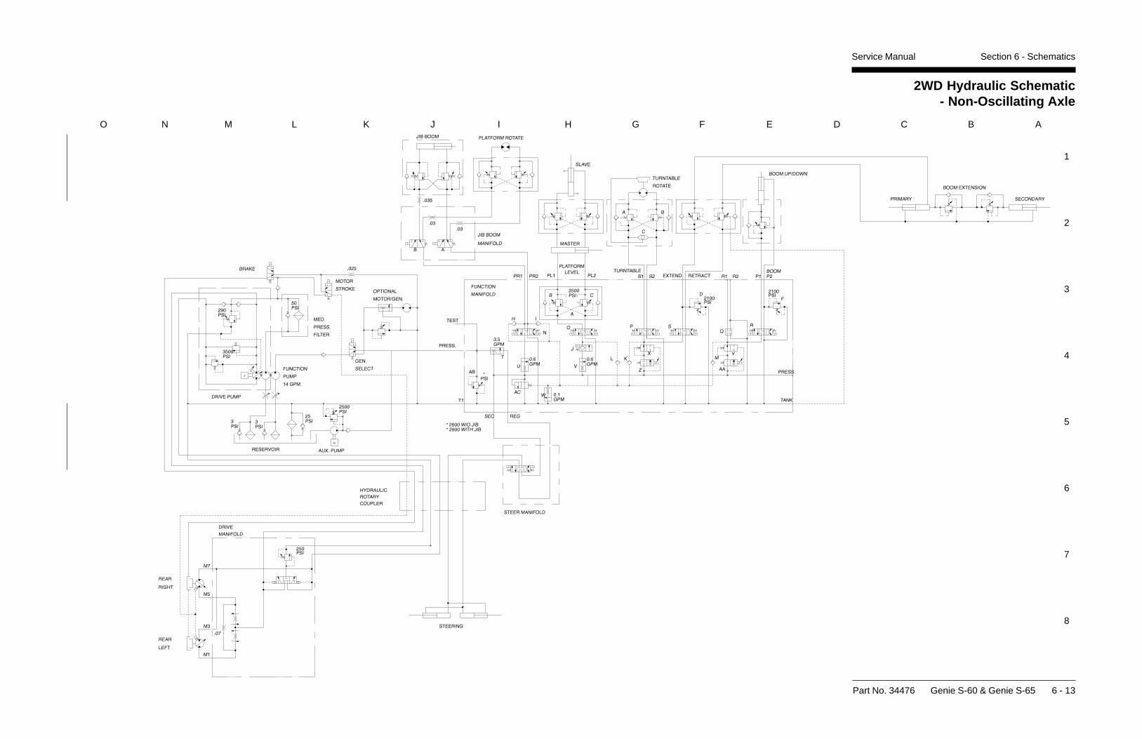
Section 6 - SchematicsService Manual
2WD Hydraulic Schematic- Non-Oscillating Axle
Part No. 34476 Genie S-60 & Genie S-65 6 - 13
1
2
3
4
5
6
7
8
O N M L K J I H G F E D C B A
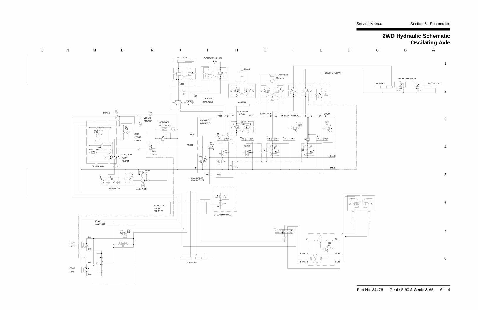
Section 6 - SchematicsService Manual
2WD Hydraulic SchematicOscilating Axle
Part No. 34476 Genie S-60 & Genie S-65 6 - 14
1
2
3
4
5
6
7
8
O N M L K J I H G F E D C B A
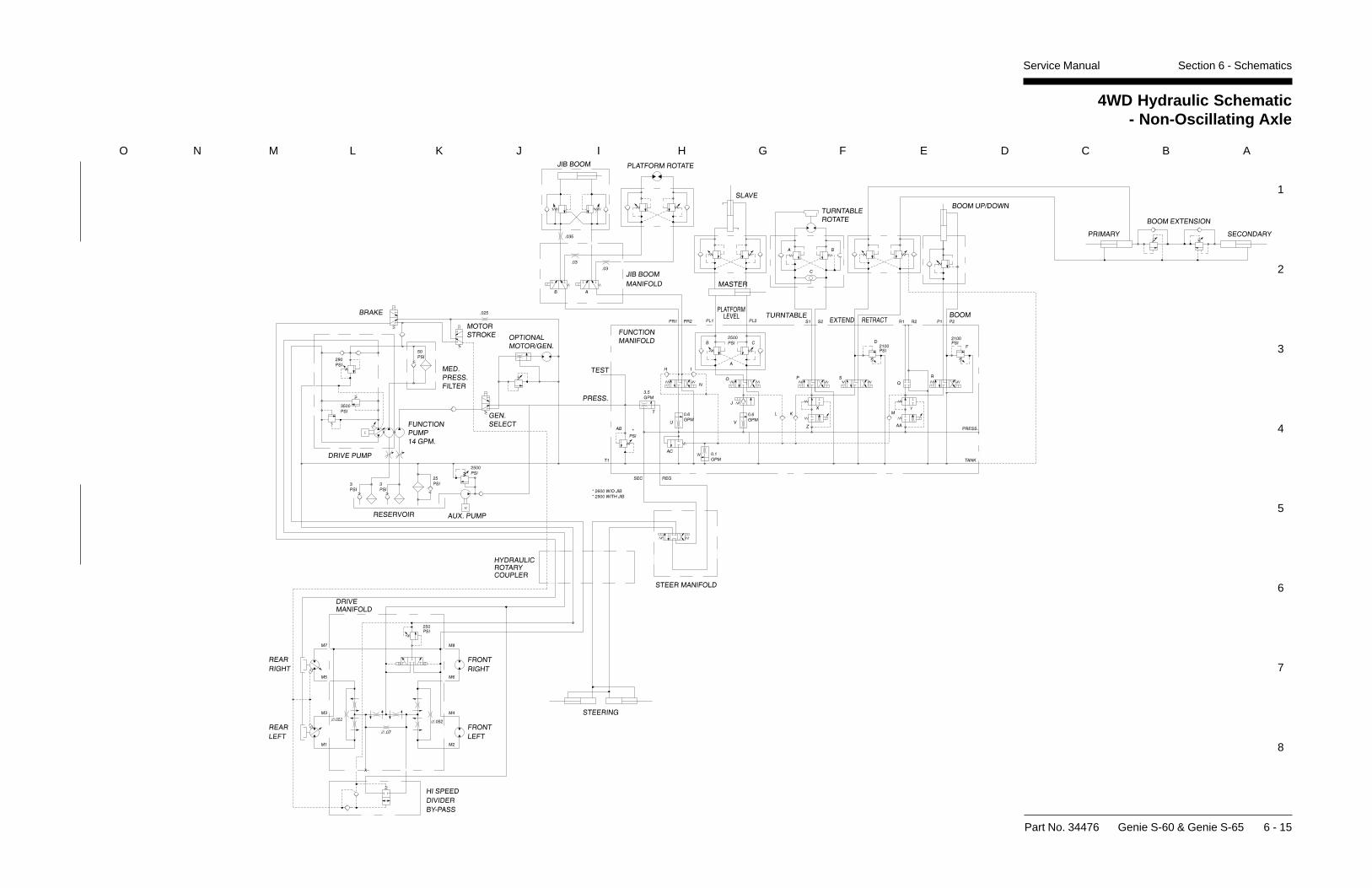
Section 6 - SchematicsService Manual
4WD Hydraulic Schematic- Non-Oscillating Axle
Part No. 34476 Genie S-60 & Genie S-65 6 - 15
1
2
3
4
5
6
7
8
O N M L K J I H G F E D C B A
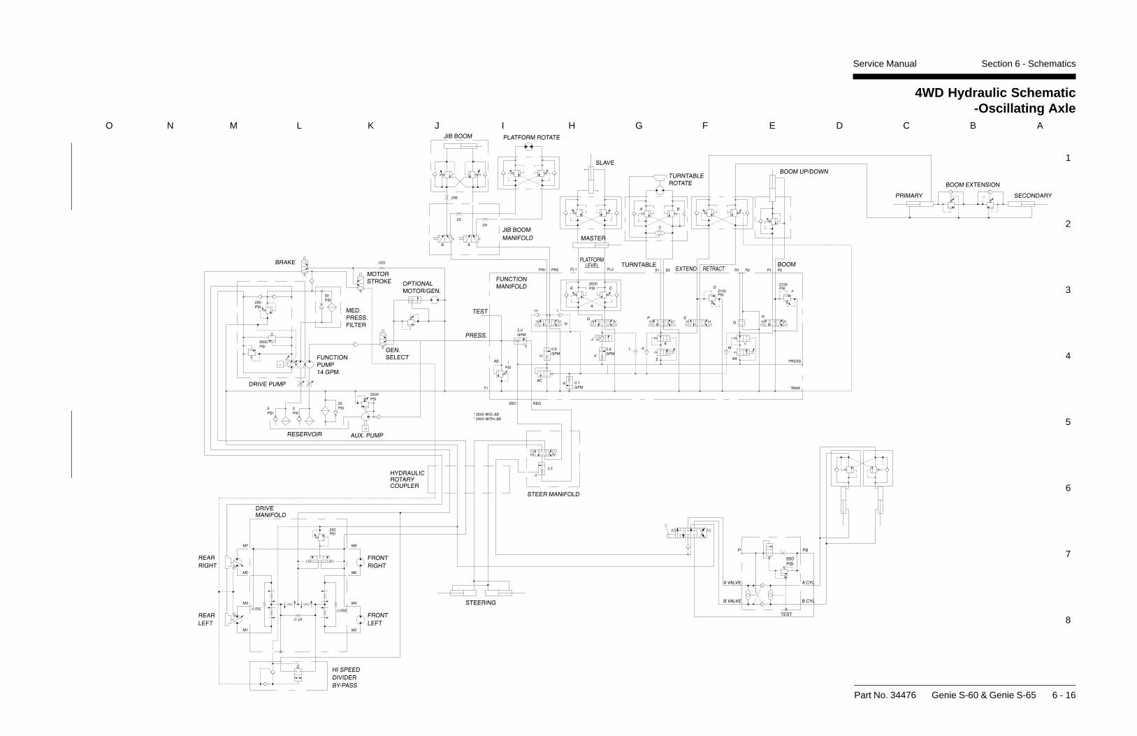
Section 6 - SchematicsService Manual
4WD Hydraulic Schematic-Oscillating Axle
Part No. 34476 Genie S-60 & Genie S-65 6 - 16
1
2
3
4
5
6
7
8
O N M L K J I H G F E D C B A
Part No. 34476 Genie S-60 & Genie S-65 7 - 1
Service Manual - First Edition Section 7 - Repair Procedures
Repair Procedures
About This SectionMost of the procedures in this section should onlybe performed by a trained service professionalin a suitably equipped workshop. Select theappropriate repair procedure after troubleshootingthe problem.
Perform disassembly procedures to the pointwhere repairs can be completed. Then tore-assemble, perform the disassembly steps inreverse order.
General Repair Process
Symbols Legend
Indicates the presence of ahazard that will cause deathor serious injury.
Indicates the presence of ahazard that may cause deathor serious injury.
Indicates the presence of ahazard that will or may causeserious personal injury ordamage to the machine.
Indicates special operation ormaintenance information.
Indicates that a specific result is expectedafter performing a series of steps.
Observe and Obey:Repair procedures shall be completed by aperson trained and qualified on the repair ofthis machine.
Immediately tag and remove from service adamaged or malfunctioning machine.
Repair any machine damage or malfunctionbefore operating the machine.
Before Repairs Start:Read, understand and obey the safety rulesand operating instructions in theGenie S-60 & Genie S-65 Operator’s Manual.
Be sure that all necessary tools and parts areavailable and ready for use.
Read each procedure completely and adhereto the instructions. Attempting shortcuts mayproduce hazardous conditions.
Unless otherwise specified, perform eachrepair procedure with the machine in thefollowing configuration:
· machine parked on a flat, level surface
· boom in stowed position
· turntable rotated with the boom between the non-steering wheels
· turntable secured with the turntable rotation lock pin
· key switch in the OFF position with the key removed
· wheels chocked
Malfunctiondiscovered
Identifysymptoms
Troubleshoot
Performrepair
Return toservice problem
solved
problemstill exists
Inspectand test
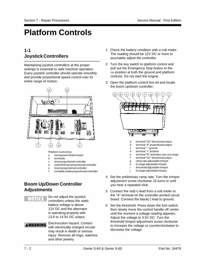
7 - 2 Genie S-60 & Genie S-65 Part No. 34476
Service Manual - First EditionSection 7 - Repair Procedures
1-1Joystick Controllers
Maintaining joystick controllers at the propersettings is essential to safe machine operation.Every joystick controller should operate smoothlyand provide proportional speed control over itsentire range of motion.
Platform control boxa horsepower limiter boardb terminalsc drive proportional controllerd extend/retract proportional controllere boom proportional controllerf turntable rotate proportional controller
Boom Up/Down ControllerAdjustments
Do not adjust the joystickcontrollers unless the staticbattery voltage is above12V DC and the alternatoris operating properly with13.6 to 14.5V DC output.
Electrocution hazard. Contactwith electrically charged circuitsmay result in death or seriousinjury. Remove all rings, watchesand other jewelry.
1 Check the battery condition with a volt meter.The reading should be 12V DC or more toaccurately adjust the controller.
2 Turn the key switch to platform control andpull out the Emergency Stop button to theON position at both the ground and platformcontrols. Do not start the engine.
3 Open the platform control box lid and locatethe boom up/down controller.
a terminal "D2" directional outputb terminal "A" proportional outputc terminal "-" groundd terminal "+" positivee terminal "R" activates max-out rangef terminal "D1" directional outputg ramp rate adjustable trimpoth lo range adjustable trimpoti threshold adjustable trimpotj hi range adjustable trimpot
4 Set the preliminary ramp rate: Turn the trimpotadjustment screw clockwise 15 turns or untilyou hear a repeated click.
5 Connect the red(+) lead from a volt meter tothe “A” terminal on the controller printed circuitboard. Connect the black(-) lead to ground.
6 Set the threshold: Press down the foot switch,then slowly move the control handle off centeruntil the moment a voltage reading appears.Adjust the voltage to 3.5V DC. Turn thethreshold trimpot adjustment screw clockwiseto increase the voltage or counterclockwise todecrease the voltage.
Platform Controls
a b c d e f g h i j
b
c
a
def

Part No. 34476 Genie S-60 & Genie S-65 7 - 3
Service Manual - First Edition Section 7 - Repair Procedures
Turntable Rotation ControllerAdjustments
Do not adjust the joystickcontrollers unless the staticbattery voltage is above12V DC and the alternator isoperating properly with13.6 to 14.5V DC output.
Electrocution hazard. Contactwith electrically charged circuitsmay result in death or seriousinjury. Remove all rings, watchesand other jewelry.
1 Check the battery condition with a volt meter.The reading should be 12V DC or more toaccurately adjust the controller.
2 Turn the key switch to platform control andpull out the Emergency Stop button tothe ON position at both the ground andplatform controls. Do not start the engine.
16 Start a timer and simultaneously move thecontrol handle all the way to the UP position.Note how long it takes to reach the maximumvoltage recorded in step 14. This is theramp speed.
17 Set the ramp rate: turn the trimpot to obtaina 3 to 4 second ramp speed. Turn thetrimpot clockwise to increase the time orcounterclockwise to decrease the time.
Boom up/down specifications
Threshold 3.5V DC
Boom up - hi range 8.5V DCCycle time 55 to 85 seconds
Boom down - lo range 6.2V DCCycle time 90 to 120 seconds
Ramp rate 3 to 4 seconds
7 Set the hi range: Press down the foot switch,then move the control handle all the way tothe UP position. Adjust the voltage to 8.5V DC.Turn the max-out trimpot adjustment screwclockwise to increase the voltage orcounterclockwise to decrease the voltage.
8 Set the lo range: Press down the foot switch,then move the control handle all the way to theDOWN position. Adjust the voltageto 6.2V DC. Turn the dual range trimpotadjustment screw clockwise to increase thevoltage or counterclockwise to decreasethe voltage.
9 Start the engine and move the engine idlecontrol switch to foot switch activated highidle (rabbit and foot switch symbol). Lowerthe boom to the stowed position.
Engine should be at normaloperating temperature.
10 Start a timer and record how long it takes forthe boom to fully raise. Adjust themax-out trimpot to achieve a 55 to 85 secondcycle time.
11 Start a timer and record how long it takes forthe boom to fully lower. Adjust the dual rangetrimpot to achieve an 90 to 120 second cycletime.
If the function cycle time is notachievable, check the relief valvepressure. See 10-2, ValveAdjustments - Function Manifold.
12 Turn the engine off and re-connect thevolt meter.
13 Pull out the Emergency Stop button tothe ON position.
14 Press down the foot switch and then move thecontrol handle all the way to the UP position.Record the maximum voltage reading.
15 Start the engine.
PLATFORM CONTROLS
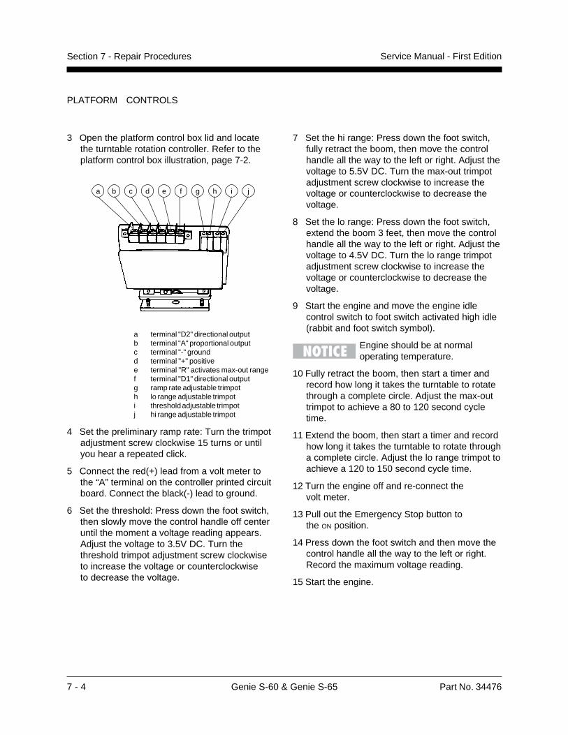
7 - 4 Genie S-60 & Genie S-65 Part No. 34476
Service Manual - First EditionSection 7 - Repair Procedures
PLATFORM CONTROLS
3 Open the platform control box lid and locatethe turntable rotation controller. Refer to theplatform control box illustration, page 7-2.
a terminal "D2" directional outputb terminal "A" proportional outputc terminal "-" groundd terminal "+" positivee terminal "R" activates max-out rangef terminal "D1" directional outputg ramp rate adjustable trimpoth lo range adjustable trimpoti threshold adjustable trimpotj hi range adjustable trimpot
4 Set the preliminary ramp rate: Turn the trimpotadjustment screw clockwise 15 turns or untilyou hear a repeated click.
5 Connect the red(+) lead from a volt meter tothe “A” terminal on the controller printed circuitboard. Connect the black(-) lead to ground.
6 Set the threshold: Press down the foot switch,then slowly move the control handle off centeruntil the moment a voltage reading appears.Adjust the voltage to 3.5V DC. Turn thethreshold trimpot adjustment screw clockwiseto increase the voltage or counterclockwiseto decrease the voltage.
a b c d e f g h i j
7 Set the hi range: Press down the foot switch,fully retract the boom, then move the controlhandle all the way to the left or right. Adjust thevoltage to 5.5V DC. Turn the max-out trimpotadjustment screw clockwise to increase thevoltage or counterclockwise to decrease thevoltage.
8 Set the lo range: Press down the foot switch,extend the boom 3 feet, then move the controlhandle all the way to the left or right. Adjust thevoltage to 4.5V DC. Turn the lo range trimpotadjustment screw clockwise to increase thevoltage or counterclockwise to decrease thevoltage.
9 Start the engine and move the engine idlecontrol switch to foot switch activated high idle(rabbit and foot switch symbol).
Engine should be at normaloperating temperature.
10 Fully retract the boom, then start a timer andrecord how long it takes the turntable to rotatethrough a complete circle. Adjust the max-outtrimpot to achieve a 80 to 120 second cycletime.
11 Extend the boom, then start a timer and recordhow long it takes the turntable to rotate througha complete circle. Adjust the lo range trimpot toachieve a 120 to 150 second cycle time.
12 Turn the engine off and re-connect thevolt meter.
13 Pull out the Emergency Stop button tothe ON position.
14 Press down the foot switch and then move thecontrol handle all the way to the left or right.Record the maximum voltage reading.
15 Start the engine.
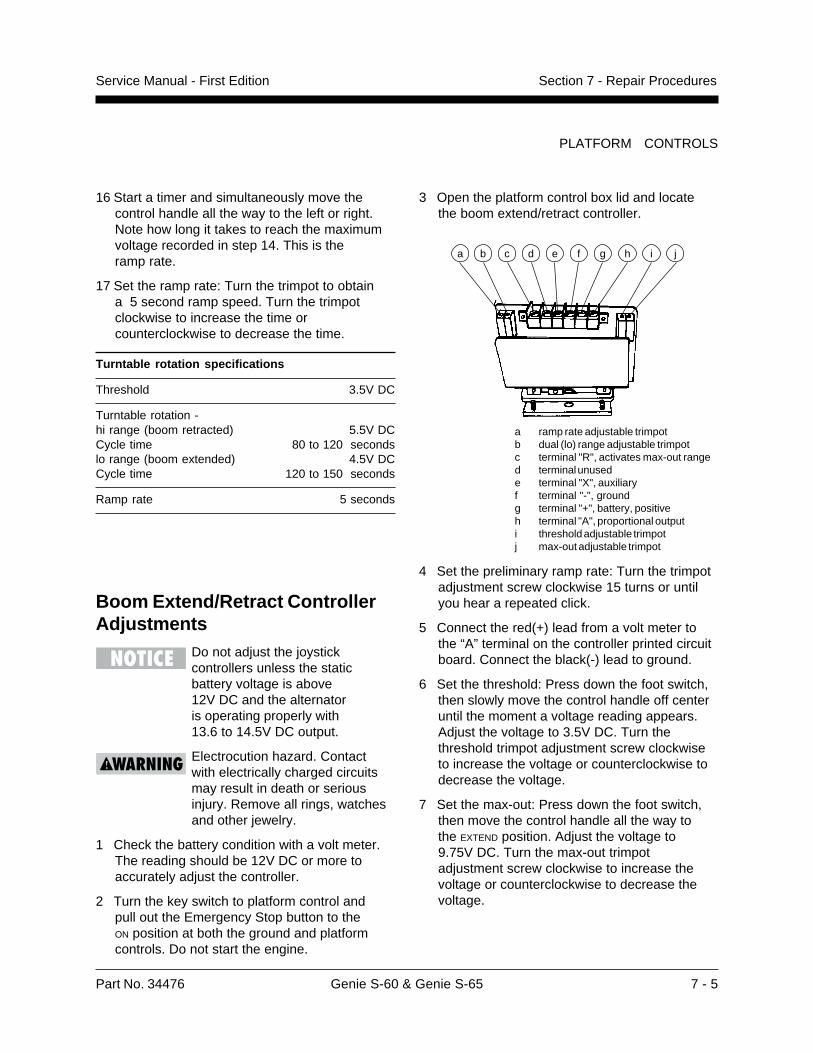
Part No. 34476 Genie S-60 & Genie S-65 7 - 5
Service Manual - First Edition Section 7 - Repair Procedures
3 Open the platform control box lid and locatethe boom extend/retract controller.
a ramp rate adjustable trimpotb dual (lo) range adjustable trimpotc terminal "R", activates max-out ranged terminal unusede terminal "X", auxiliaryf terminal "-", groundg terminal "+", battery, positiveh terminal "A", proportional outputi threshold adjustable trimpotj max-out adjustable trimpot
4 Set the preliminary ramp rate: Turn the trimpotadjustment screw clockwise 15 turns or untilyou hear a repeated click.
5 Connect the red(+) lead from a volt meter tothe “A” terminal on the controller printed circuitboard. Connect the black(-) lead to ground.
6 Set the threshold: Press down the foot switch,then slowly move the control handle off centeruntil the moment a voltage reading appears.Adjust the voltage to 3.5V DC. Turn thethreshold trimpot adjustment screw clockwiseto increase the voltage or counterclockwise todecrease the voltage.
7 Set the max-out: Press down the foot switch,then move the control handle all the way tothe EXTEND position. Adjust the voltage to9.75V DC. Turn the max-out trimpotadjustment screw clockwise to increase thevoltage or counterclockwise to decrease thevoltage.
PLATFORM CONTROLS
Boom Extend/Retract ControllerAdjustments
Do not adjust the joystickcontrollers unless the staticbattery voltage is above12V DC and the alternatoris operating properly with13.6 to 14.5V DC output.
Electrocution hazard. Contactwith electrically charged circuitsmay result in death or seriousinjury. Remove all rings, watchesand other jewelry.
1 Check the battery condition with a volt meter.The reading should be 12V DC or more toaccurately adjust the controller.
2 Turn the key switch to platform control andpull out the Emergency Stop button to theON position at both the ground and platformcontrols. Do not start the engine.
a b c d e f g h i j
16 Start a timer and simultaneously move thecontrol handle all the way to the left or right.Note how long it takes to reach the maximumvoltage recorded in step 14. This is theramp rate.
17 Set the ramp rate: Turn the trimpot to obtaina 5 second ramp speed. Turn the trimpotclockwise to increase the time orcounterclockwise to decrease the time.
Turntable rotation specifications
Threshold 3.5V DC
Turntable rotation -hi range (boom retracted) 5.5V DCCycle time 80 to 120 secondslo range (boom extended) 4.5V DCCycle time 120 to 150 seconds
Ramp rate 5 seconds
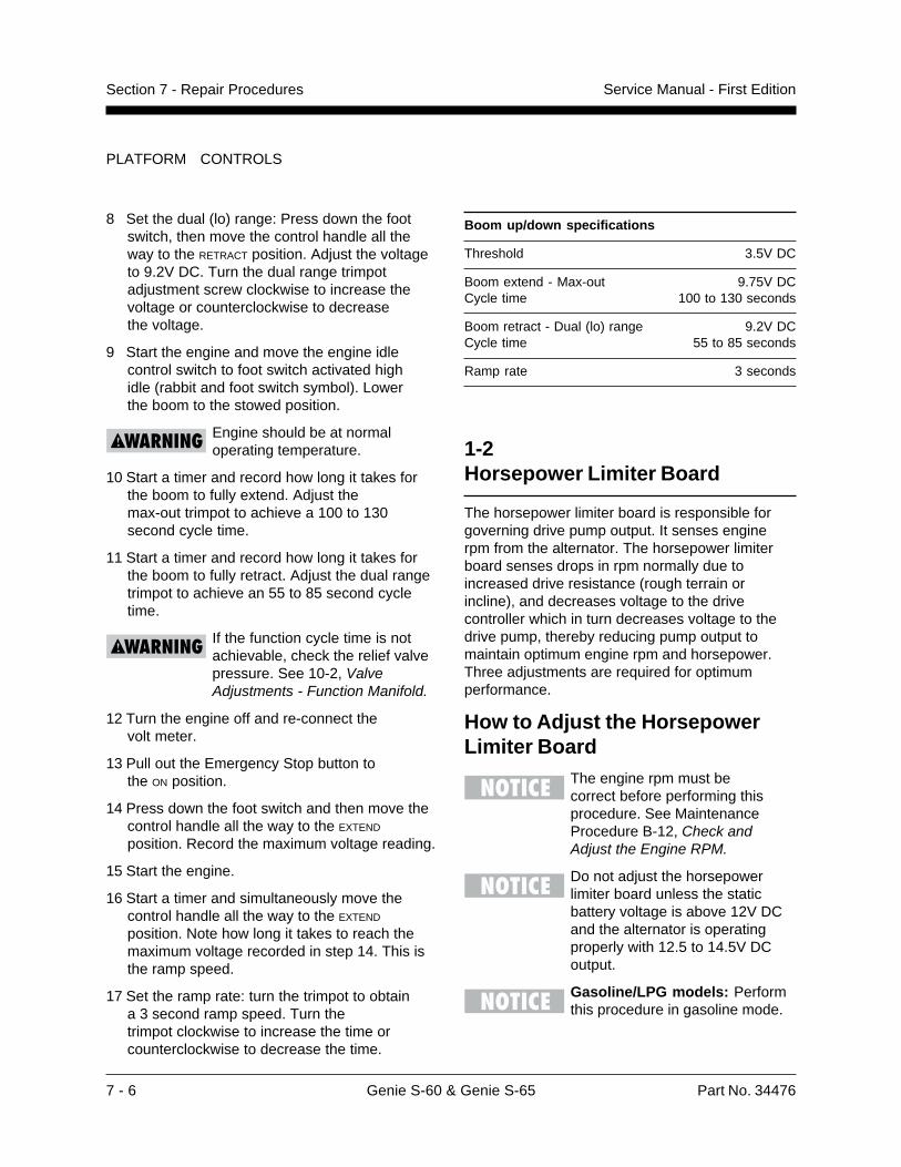
7 - 6 Genie S-60 & Genie S-65 Part No. 34476
Service Manual - First EditionSection 7 - Repair Procedures
8 Set the dual (lo) range: Press down the footswitch, then move the control handle all theway to the RETRACT position. Adjust the voltageto 9.2V DC. Turn the dual range trimpotadjustment screw clockwise to increase thevoltage or counterclockwise to decreasethe voltage.
9 Start the engine and move the engine idlecontrol switch to foot switch activated highidle (rabbit and foot switch symbol). Lowerthe boom to the stowed position.
Engine should be at normaloperating temperature.
10 Start a timer and record how long it takes forthe boom to fully extend. Adjust themax-out trimpot to achieve a 100 to 130second cycle time.
11 Start a timer and record how long it takes forthe boom to fully retract. Adjust the dual rangetrimpot to achieve an 55 to 85 second cycletime.
If the function cycle time is notachievable, check the relief valvepressure. See 10-2, ValveAdjustments - Function Manifold.
12 Turn the engine off and re-connect thevolt meter.
13 Pull out the Emergency Stop button tothe ON position.
14 Press down the foot switch and then move thecontrol handle all the way to the EXTEND
position. Record the maximum voltage reading.
15 Start the engine.
16 Start a timer and simultaneously move thecontrol handle all the way to the EXTEND
position. Note how long it takes to reach themaximum voltage recorded in step 14. This isthe ramp speed.
17 Set the ramp rate: turn the trimpot to obtaina 3 second ramp speed. Turn thetrimpot clockwise to increase the time orcounterclockwise to decrease the time.
PLATFORM CONTROLS
Boom up/down specifications
Threshold 3.5V DC
Boom extend - Max-out 9.75V DCCycle time 100 to 130 seconds
Boom retract - Dual (lo) range 9.2V DCCycle time 55 to 85 seconds
Ramp rate 3 seconds
1-2Horsepower Limiter Board
The horsepower limiter board is responsible forgoverning drive pump output. It senses enginerpm from the alternator. The horsepower limiterboard senses drops in rpm normally due toincreased drive resistance (rough terrain orincline), and decreases voltage to the drivecontroller which in turn decreases voltage to thedrive pump, thereby reducing pump output tomaintain optimum engine rpm and horsepower.Three adjustments are required for optimumperformance.
How to Adjust the HorsepowerLimiter Board
The engine rpm must becorrect before performing thisprocedure. See MaintenanceProcedure B-12, Check andAdjust the Engine RPM.
Do not adjust the horsepowerlimiter board unless the staticbattery voltage is above 12V DCand the alternator is operatingproperly with 12.5 to 14.5V DCoutput.
Gasoline/LPG models: Performthis procedure in gasoline mode.
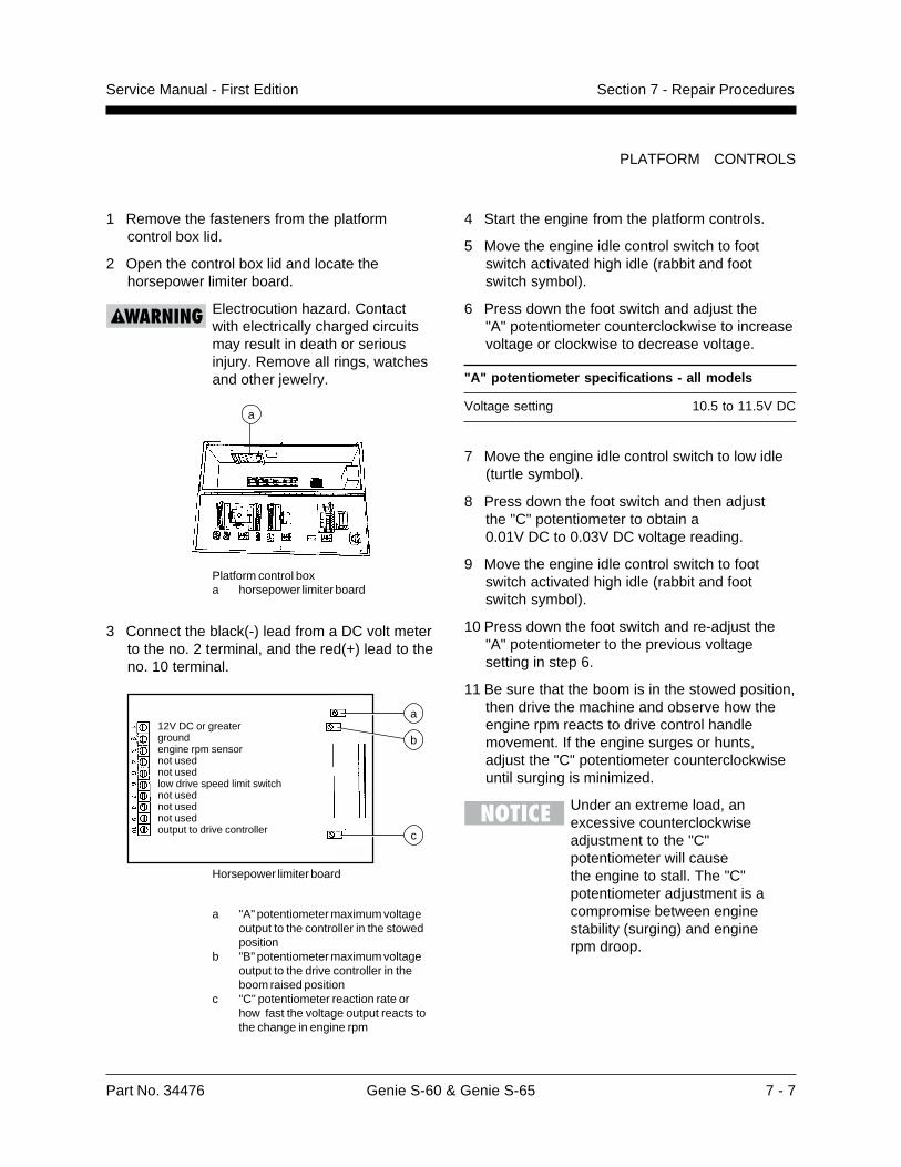
Part No. 34476 Genie S-60 & Genie S-65 7 - 7
Service Manual - First Edition Section 7 - Repair Procedures
PLATFORM CONTROLS
4 Start the engine from the platform controls.
5 Move the engine idle control switch to footswitch activated high idle (rabbit and footswitch symbol).
6 Press down the foot switch and adjust the"A" potentiometer counterclockwise to increasevoltage or clockwise to decrease voltage.
"A" potentiometer specifications - all models
Voltage setting 10.5 to 11.5V DC
7 Move the engine idle control switch to low idle(turtle symbol).
8 Press down the foot switch and then adjustthe "C" potentiometer to obtain a0.01V DC to 0.03V DC voltage reading.
9 Move the engine idle control switch to footswitch activated high idle (rabbit and footswitch symbol).
10 Press down the foot switch and re-adjust the"A" potentiometer to the previous voltagesetting in step 6.
11 Be sure that the boom is in the stowed position,then drive the machine and observe how theengine rpm reacts to drive control handlemovement. If the engine surges or hunts,adjust the "C" potentiometer counterclockwiseuntil surging is minimized.
Under an extreme load, anexcessive counterclockwiseadjustment to the "C"potentiometer will causethe engine to stall. The "C"potentiometer adjustment is acompromise between enginestability (surging) and enginerpm droop.
1 Remove the fasteners from the platformcontrol box lid.
2 Open the control box lid and locate thehorsepower limiter board.
Electrocution hazard. Contactwith electrically charged circuitsmay result in death or seriousinjury. Remove all rings, watchesand other jewelry.
Platform control boxa horsepower limiter board
3 Connect the black(-) lead from a DC volt meterto the no. 2 terminal, and the red(+) lead to theno. 10 terminal.
Horsepower limiter board
a "A" potentiometer maximum voltageoutput to the controller in the stowedposition
b "B" potentiometer maximum voltageoutput to the drive controller in theboom raised position
c "C" potentiometer reaction rate orhow fast the voltage output reacts tothe change in engine rpm
12V DC or greatergroundengine rpm sensornot usednot usedlow drive speed limit switchnot usednot usednot usedoutput to drive controller
b
a
c
a
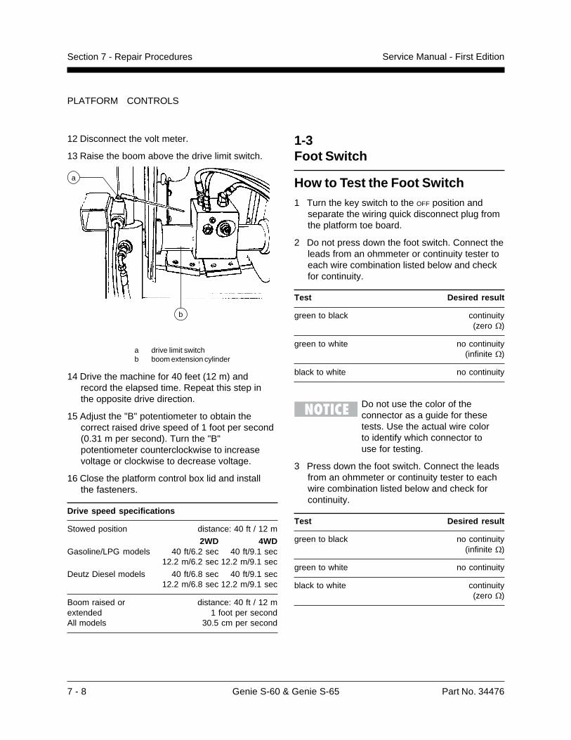
7 - 8 Genie S-60 & Genie S-65 Part No. 34476
Service Manual - First EditionSection 7 - Repair Procedures
PLATFORM CONTROLS
12 Disconnect the volt meter.
13 Raise the boom above the drive limit switch.
a drive limit switchb boom extension cylinder
14 Drive the machine for 40 feet (12 m) andrecord the elapsed time. Repeat this step inthe opposite drive direction.
15 Adjust the "B" potentiometer to obtain thecorrect raised drive speed of 1 foot per second(0.31 m per second). Turn the "B"potentiometer counterclockwise to increasevoltage or clockwise to decrease voltage.
16 Close the platform control box lid and installthe fasteners.
Drive speed specifications
Stowed position distance: 40 ft / 12 m
2WD 4WDGasoline/LPG models 40 ft/6.2 sec 40 ft/9.1 sec
12.2 m/6.2 sec 12.2 m/9.1 sec
Deutz Diesel models 40 ft/6.8 sec 40 ft/9.1 sec12.2 m/6.8 sec 12.2 m/9.1 sec
Boom raised or distance: 40 ft / 12 mextended 1 foot per secondAll models 30.5 cm per second
a
b
1-3Foot Switch
How to Test the Foot Switch1 Turn the key switch to the OFF position and
separate the wiring quick disconnect plug fromthe platform toe board.
2 Do not press down the foot switch. Connect theleads from an ohmmeter or continuity tester toeach wire combination listed below and checkfor continuity.
Test Desired result
green to black continuity(zero �)
green to white no continuity(infinite �)
black to white no continuity
Do not use the color of theconnector as a guide for thesetests. Use the actual wire colorto identify which connector touse for testing.
3 Press down the foot switch. Connect the leadsfrom an ohmmeter or continuity tester to eachwire combination listed below and check forcontinuity.
Test Desired result
green to black no continuity(infinite �)
green to white no continuity
black to white continuity(zero �)
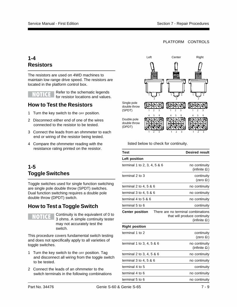
Part No. 34476 Genie S-60 & Genie S-65 7 - 9
Service Manual - First Edition Section 7 - Repair Procedures
1
2
3
4 5 6
1 2 3
1
2
3 1
2
3
1 2 3 1 2 3
1 2 3 1 2 3 1 2 3
4 5 6 4 5 6
PLATFORM CONTROLS
1-4Resistors
The resistors are used on 4WD machines tomaintain low range drive speed. The resistors arelocated in the platform control box.
Refer to the schematic legendsfor resistor locations and values.
How to Test the Resistors1 Turn the key switch to the OFF position.
2 Disconnect either end of one of the wiresconnected to the resistor to be tested.
3 Connect the leads from an ohmmeter to eachend or wiring of the resistor being tested.
4 Compare the ohmmeter reading with theresistance rating printed on the resistor.
1-5Toggle Switches
Toggle switches used for single function switchingare single pole double throw (SPDT) switches.Dual function switching requires a double poledouble throw (DPDT) switch.
How to Test a Toggle SwitchContinuity is the equivalent of 0 to3 ohms. A simple continuity testermay not accurately test theswitch.
This procedure covers fundamental switch testingand does not specifically apply to all varieties oftoggle switches.
1 Turn the key switch to the OFF position. Tagand disconnect all wiring from the toggle switchto be tested.
2 Connect the leads of an ohmmeter to theswitch terminals in the following combinations
CenterLeft Right
Single poledouble throw(SPDT)
Double poledouble throw(DPDT)
listed below to check for continuity.
Test Desired result
Left position
terminal 1 to 2, 3, 4, 5 & 6 no continuity(infinite �)
terminal 2 to 3 continuity(zero �)
terminal 2 to 4, 5 & 6 no continuity
terminal 3 to 4, 5 & 6 no continuity
terminal 4 to 5 & 6 no continuity
terminal 5 to 6 continuity
Center position There are no terminal combinationsthat will produce continuity
(infinite �)
Right position
terminal 1 to 2 continuity(zero �)
terminal 1 to 3, 4, 5 & 6 no continuity(infinite �)
terminal 2 to 3, 4, 5 & 6 no continuity
terminal 3 to 4, 5 & 6 no continuity
terminal 4 to 5 continuity
terminal 4 to 6 no continuity
terminal 5 to 6 no continuity
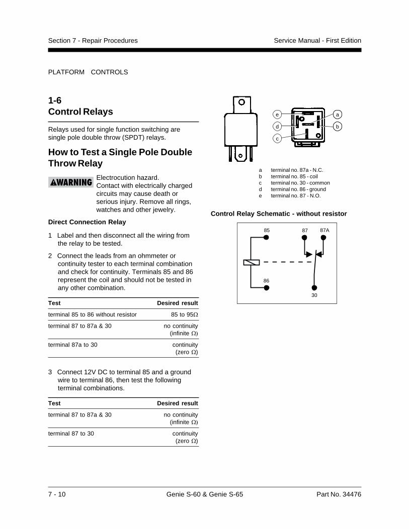
7 - 10 Genie S-60 & Genie S-65 Part No. 34476
Service Manual - First EditionSection 7 - Repair Procedures
PLATFORM CONTROLS
1-6Control Relays
Relays used for single function switching aresingle pole double throw (SPDT) relays.
How to Test a Single Pole DoubleThrow Relay
Electrocution hazard.Contact with electrically chargedcircuits may cause death orserious injury. Remove all rings,watches and other jewelry.
Direct Connection Relay
1 Label and then disconnect all the wiring fromthe relay to be tested.
2 Connect the leads from an ohmmeter orcontinuity tester to each terminal combinationand check for continuity. Terminals 85 and 86represent the coil and should not be tested inany other combination.
Test Desired result
terminal 85 to 86 without resistor 85 to 95�
terminal 87 to 87a & 30 no continuity(infinite ��
terminal 87a to 30 continuity(zero �)
3 Connect 12V DC to terminal 85 and a groundwire to terminal 86, then test the followingterminal combinations.
Test Desired result
terminal 87 to 87a & 30 no continuity(infinite ��
terminal 87 to 30 continuity(zero �)
d
e
c
a
b
a terminal no. 87a - N.C.b terminal no. 85 - coilc terminal no. 30 - commond terminal no. 86 - grounde terminal no. 87 - N.O.
Control Relay Schematic - without resistor
85
86
87 87A
30
Part No. 34476 Genie S-60 & Genie S-65 7 - 11
Service Manual - First Edition Section 7 - Repair Procedures
3 Remove the pin retainer fastener fromthe rod-end pin.
4 Remove the external retaining ring from thebarrel-end pin.
5 Use a soft metal drift to drive the rod-end pinout.
6 Use a soft metal drift and drive the barrel-endpin out.
7 Carefully pull the cylinder out of the boom.
8 Disconnect the hydraulic hoses from theslave cylinder and connect them togetherwith a connector. Cap the fittings on thecylinder.
Bodily injury hazard. Sprayinghydraulic oil can penetrate andburn skin. Loosen hydraulicconnections very slowly to allowthe oil pressure to dissipategradually. Do not allow oil tosquirt or spray.
Platform Components
2-1Platform
How to Remove the Platform1 Remove the cable harness from the cable
clamp located on the platform mountingbracket and separate the foot switch quickdisconnect plug.
2 Remove the platform control box mountingbolts, then lower the control box andset it aside.
If your machine is equipped withan airline to platform option, theairline must be disconnected fromthe platform before removal.
3 Remove the platform mounting bolts and lift theplatform off the mount.
2-2Platform Leveling Slave Cylinder
The slave cylinder and the rotator pivot are thetwo primary supports for the platform. The slavecylinder keeps the platform level through theentire range of boom motion. It operates in aclosed-circuit hydraulic loop with the mastercylinder. The slave cylinder is equipped withcounterbalance valves to prevent movement inthe event of a hydraulic line failure.
How to Remove the SlaveCylinder
Before cylinder removal isconsidered, bleed the slavecylinder to be sure there is noair in the closed loop.
1 Extend the boom until the slave cylinderbarrel-end pivot pin is accessible.
2 Raise the boom slightly and place blocks underthe platform. Then lower the boom until theplatform is resting on the blocks.

7 - 12 Genie S-60 & Genie S-65 Part No. 34476
Service Manual - First EditionSection 7 - Repair Procedures
How to Bleed the Slave CylinderDo not start the engine. Useauxiliary power for all machinefunctions in this procedure.
1 Raise the boom to a horizontal position.
2 Move the platform level switch up and downthrough two platform leveling cycles to removeany air that might be in the system.
PLATFORM COMPONENTS
2-3Platform Rotator
The platform rotator is a hydraulically activatedhelical gear assembly used to rotate the platform160 degrees.
How to Remove thePlatform Rotator
Component damage hazard. Markthe platform mounting weldmentand the rotator flange beforeremoving the platform mountingweldment. The platform mountingweldment must be replaced in theexact same position on the rotatorflange as it was before removal. Ifa new rotator is installed or therotator is disassembled, properalignment can be achieved byrotating the rotator all the way tothe left and then installing theplatform mounting weldment allthe way in the left position.
1 Remove the platform. See 2-1,How to Remove the Platform.
2 Disconnect and plug the hydraulic hoses fromthe platform rotator manifold.
Bodily injury hazard. Sprayinghydraulic oil can penetrate andburn skin. Loosen hydraulicconnections very slowly to allowthe oil pressure to dissipategradually. Do not allow oil to squirtor spray.
3 Support the platform mounting weldment, butdo not apply any lifting pressure.
4 Remove the six mounting bolts from theplatform mounting weldment, then remove thecenter bolt and slide the platform mountingweldment off of the platform rotator.
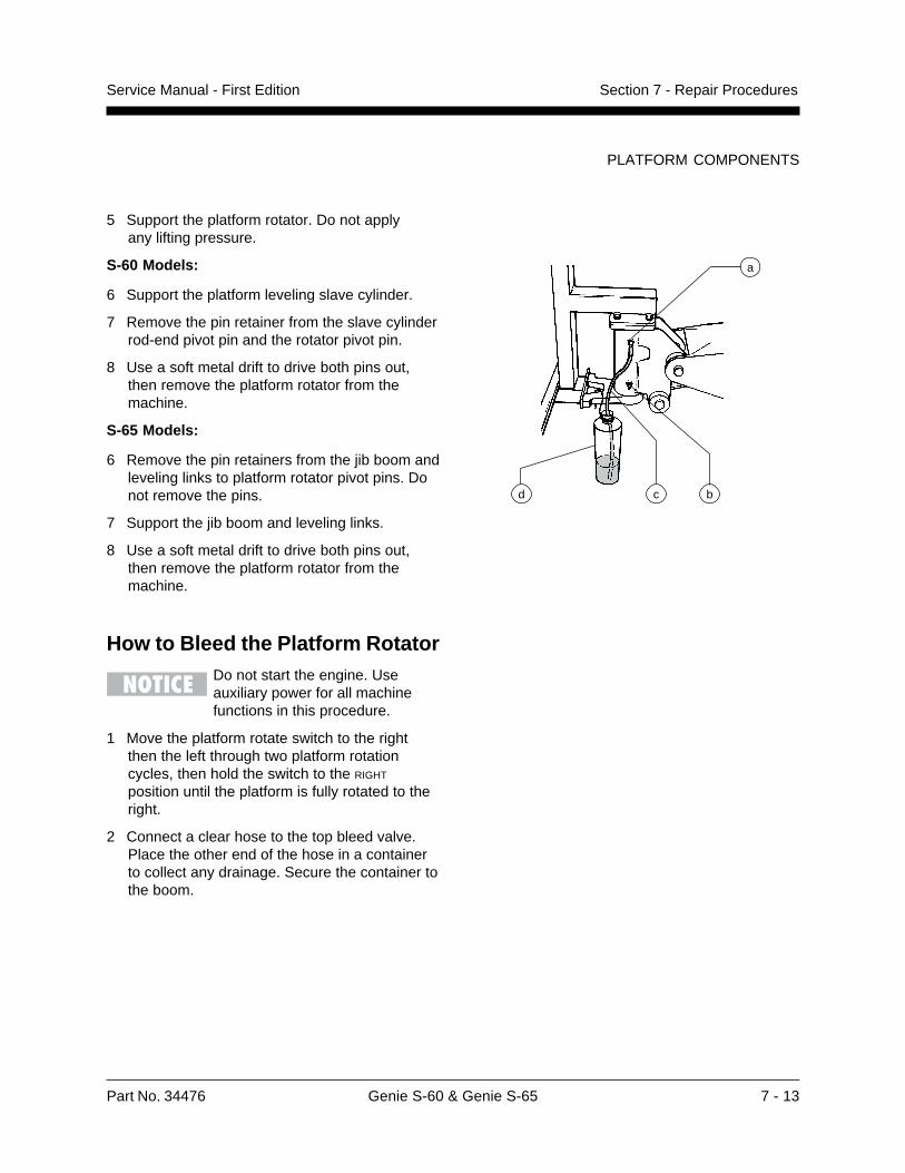
Part No. 34476 Genie S-60 & Genie S-65 7 - 13
Service Manual - First Edition Section 7 - Repair Procedures
PLATFORM COMPONENTS
5 Support the platform rotator. Do not applyany lifting pressure.
S-60 Models:
6 Support the platform leveling slave cylinder.
7 Remove the pin retainer from the slave cylinderrod-end pivot pin and the rotator pivot pin.
8 Use a soft metal drift to drive both pins out,then remove the platform rotator from themachine.
S-65 Models:
6 Remove the pin retainers from the jib boom andleveling links to platform rotator pivot pins. Donot remove the pins.
7 Support the jib boom and leveling links.
8 Use a soft metal drift to drive both pins out,then remove the platform rotator from themachine.
How to Bleed the Platform RotatorDo not start the engine. Useauxiliary power for all machinefunctions in this procedure.
1 Move the platform rotate switch to the rightthen the left through two platform rotationcycles, then hold the switch to the RIGHT
position until the platform is fully rotated to theright.
2 Connect a clear hose to the top bleed valve.Place the other end of the hose in a containerto collect any drainage. Secure the container tothe boom.
a
d c b
7 - 14 Genie S-60 & Genie S-65 Part No. 34476
Service Manual - First EditionSection 7 - Repair Procedures
3-1Jib Boom - S-65 Models
How to Remove the Jib BoomPerform this procedure with theboom in the stowed position.
1 Remove the platform. See 2-1,How to Remove the Platform.
2 Remove the platform mounting weldmentand the platform rotator. See 2-3, How toRemove the Platform Rotator.
3 Support the platform pivot weldment with alifting device.
4 Disconnect and plug the jib boom lift cylinderhydraulic hoses.
Bodily injury hazard. Sprayinghydraulic oil can penetrate andburn skin. Loosen hydraulicconnections very slowly to allowthe oil pressure to dissipategradually. Do not allow oil tosquirt or spray.
5 Remove the pin retainer from the jib boom liftcylinder barrel-end pivot pin. Use a soft metaldrift to remove the pin.
6 Tag, disconnect and plug all the hydraulichoses from the jib boom manifold.
Bodily injury hazard. Sprayinghydraulic oil can penetrate andburn skin. Loosen hydraulicconnections very slowly to allowthe oil pressure to dissipategradually. Do not allow oil tosquirt or spray.
7 Remove the cable tray from the side of thejib boom.
8 Support the jib boom with an overhead crane.
9 Remove the pin retainer from the jib boompivot pin. Use a soft metal drift to remove thepin, then remove the jib boom from theprimary boom.
Crushing hazard. The jib boomwill fall when the pin is removedif it is not properly supported.
10 Remove the pin retainers from the jib boomlift cylinder rod-end pivot pin. Do not removethe pin.
11 Remove both of the jib boom leveling links fromthe primary boom.
12 Support the jib boom lift cylinder with anoverhead crane.
13 Use a soft metal drift to remove the jib boom liftcylinder rod-end pivot pin, then remove the jibboom lift cylinder from the primary boom.
Crushing hazard. The jib boomlift cylinder will fall when the pinis removed if it is not properlysupported.
Jib Boom Components - S-65 Models
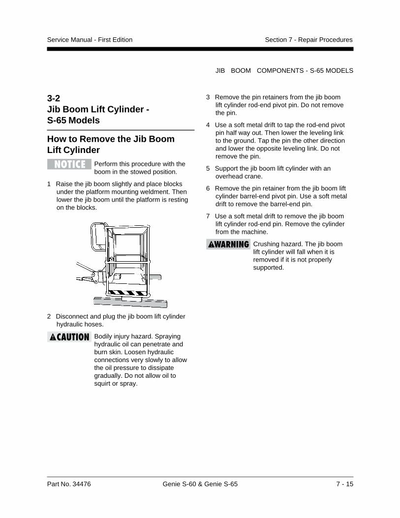
Part No. 34476 Genie S-60 & Genie S-65 7 - 15
Service Manual - First Edition Section 7 - Repair Procedures
3-2Jib Boom Lift Cylinder -S-65 Models
How to Remove the Jib BoomLift Cylinder
Perform this procedure with theboom in the stowed position.
1 Raise the jib boom slightly and place blocksunder the platform mounting weldment. Thenlower the jib boom until the platform is restingon the blocks.
2 Disconnect and plug the jib boom lift cylinderhydraulic hoses.
Bodily injury hazard. Sprayinghydraulic oil can penetrate andburn skin. Loosen hydraulicconnections very slowly to allowthe oil pressure to dissipategradually. Do not allow oil tosquirt or spray.
3 Remove the pin retainers from the jib boomlift cylinder rod-end pivot pin. Do not removethe pin.
4 Use a soft metal drift to tap the rod-end pivotpin half way out. Then lower the leveling linkto the ground. Tap the pin the other directionand lower the opposite leveling link. Do notremove the pin.
5 Support the jib boom lift cylinder with anoverhead crane.
6 Remove the pin retainer from the jib boom liftcylinder barrel-end pivot pin. Use a soft metaldrift to remove the barrel-end pin.
7 Use a soft metal drift to remove the jib boomlift cylinder rod-end pin. Remove the cylinderfrom the machine.
Crushing hazard. The jib boomlift cylinder will fall when it isremoved if it is not properlysupported.
JIB BOOM COMPONENTS - S-65 MODELS
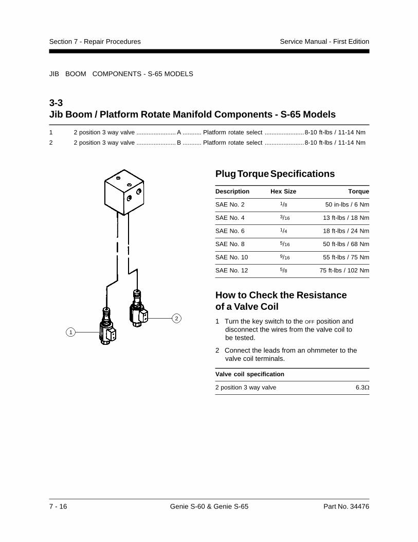
7 - 16 Genie S-60 & Genie S-65 Part No. 34476
Service Manual - First EditionSection 7 - Repair Procedures
JIB BOOM COMPONENTS - S-65 MODELS
3-3Jib Boom / Platform Rotate Manifold Components - S-65 Models
1 2 position 3 way valve ....................... A ........... Platform rotate select .......................8-10 ft-lbs / 11-14 Nm
2 2 position 3 way valve ....................... B ........... Platform rotate select .......................8-10 ft-lbs / 11-14 Nm
Plug Torque Specifications
Description Hex Size Torque
SAE No. 2 1/8 50 in-lbs / 6 Nm
SAE No. 4 3/16 13 ft-lbs / 18 Nm
SAE No. 6 1/4 18 ft-lbs / 24 Nm
SAE No. 8 5/16 50 ft-lbs / 68 Nm
SAE No. 10 9/16 55 ft-lbs / 75 Nm
SAE No. 12 5/8 75 ft-lbs / 102 Nm
How to Check the Resistanceof a Valve Coil1 Turn the key switch to the OFF position and
disconnect the wires from the valve coil tobe tested.
2 Connect the leads from an ohmmeter to thevalve coil terminals.
Valve coil specification
2 position 3 way valve 6.3�
1
2
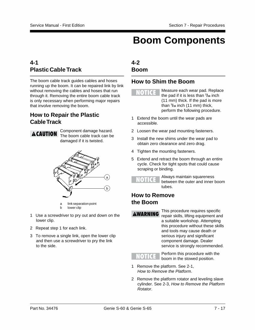
Part No. 34476 Genie S-60 & Genie S-65 7 - 17
Service Manual - First Edition Section 7 - Repair Procedures
4-1Plastic Cable Track
The boom cable track guides cables and hosesrunning up the boom. It can be repaired link by linkwithout removing the cables and hoses that runthrough it. Removing the entire boom cable trackis only necessary when performing major repairsthat involve removing the boom.
How to Repair the PlasticCable Track
Component damage hazard.The boom cable track can bedamaged if it is twisted.
a link separation pointb lower clip
1 Use a screwdriver to pry out and down on thelower clip.
2 Repeat step 1 for each link.
3 To remove a single link, open the lower clipand then use a screwdriver to pry the linkto the side.
Boom Components
a
b
4-2Boom
How to Shim the BoomMeasure each wear pad. Replacethe pad if it is less than 7/16 inch(11 mm) thick. If the pad is morethan 7/16 inch (11 mm) thick,perform the following procedure.
1 Extend the boom until the wear pads areaccessible.
2 Loosen the wear pad mounting fasteners.
3 Install the new shims under the wear pad toobtain zero clearance and zero drag.
4 Tighten the mounting fasteners.
5 Extend and retract the boom through an entirecycle. Check for tight spots that could causescraping or binding.
Always maintain squarenessbetween the outer and inner boomtubes.
How to Removethe Boom
This procedure requires specificrepair skills, lifting equipment anda suitable workshop. Attemptingthis procedure without these skillsand tools may cause death orserious injury and significantcomponent damage. Dealerservice is strongly recommended.
Perform this procedure with theboom in the stowed position.
1 Remove the platform. See 2-1,How to Remove the Platform.
2 Remove the platform rotator and leveling slavecylinder. See 2-3, How to Remove the PlatformRotator.
7 - 18 Genie S-60 & Genie S-65 Part No. 34476
Service Manual - First EditionSection 7 - Repair Procedures
BOOM COMPONENTS
S-65 Models: Remove the jib boom. See 3-1,How to Remove the Jib Boom.
3 Remove the mounting fasteners from thecounterbalance valve manifold on the end ofthe boom. Then remove the manifold and set itaside.
4 Remove the drive speed limit switchmounted on the side of the cable track. Do notdisconnect the wiring.
5 Support the cable track with an overheadcrane.
6 Remove the hose/cable cover from the pivotend of the boom.
7 Remove the cable track mounting bolts at theplatform end of the boom.
8 Remove the side panel from the cable track toaccess the cable track mounting bolts.
9 Remove the cable track mounting fasteners,then remove the cable track from theboom and lay it off to the side.
Component damage hazard.The boom cable trackcan be damaged if it is twisted.
10 Remove the turntable end cover.
11 Remove the retaining bolt from the mastercylinder rod-end pivot pin. Use a soft metal driftto remove the pin. Pull the cylinder back andsecure it from moving.
12 Remove the drive speed limit switchmounted on the inside of the pivot end ofthe boom. Do not disconnect the wiring.
13 Tag, disconnect and plug the extension cylinderhydraulic hoses. Cap the fittings on thecylinder.
Bodily injury hazard. Sprayinghydraulic oil can penetrate andburn skin. Loosen hydraulicconnections very slowly to allowthe oil pressure to dissipategradually. Do not allow oil tosquirt or spray.
14 Attach an overhead 5 ton (4536 kg) crane tothe center point of the boom.
15 Attach a similar lifting device to the lift cylinder.
16 Use the crane to lift the boom to a horizontalposition.
17 Place support blocks under the cylinder, acrossthe turntable.
18 Remove the pin retaining fastener from theboom lift cylinder rod-end pin. Use a soft metaldrift to remove the pin.
Crushing hazard. The boom liftcylinder will fall unless it isproperly supported.
19 Lower the rod end of the lift cylinder ontosupport blocks. Protect the cylinder rod fromdamage.
20 Remove the pin retaining fastener from theboom pivot pin.
21 Remove the boom pivot pin with a soft metaldrift, then carefully remove the boom from themachine.
Crushing hazard. If the overheadcrane is not properly attached,the boom may becomeunbalanced and fall when it isremoved from the machine.
How to Disassemblethe Boom
Complete disassembly of theboom is only necessaryif the outer or inner boom tubesmust be replaced. The extensioncylinder can be removed withoutcompletely disassembling theboom. See 4-4, How to Removethe Extension Cylinder.
1 Remove the boom. See 4-2,How to Remove the Boom.
Part No. 34476 Genie S-60 & Genie S-65 7 - 19
Service Manual - First Edition Section 7 - Repair Procedures
BOOM COMPONENTS
2 Place blocks under the extension cylinder forsupport.
3 Remove the retaining rings from the extensioncylinder barrel-end pivot pin at the base of thenumber 1 boom tube. Use a soft metal drift toremove the pin.
4 Remove and label the wear pads from the topside of the number 1 boom tube at the platformend of the boom.
Pay careful attention to thelocation and amount of shims usedwith each wear pad.
5 Remove the two wear pad stop bolts from eachside of the number 1 boom tube (located on theoutside).
6 Support the number 2 and 3 boom tubes withan overhead crane at the platform end of theboom.
Crushing hazard. The boom tubeswill fall when they are removedfrom the boom if they are notproperly supported.
7 Support and slide the number 2 and 3 boomtubes out of the number 1 boom tube. Place the2 and 3 boom tubes on blocks for support.
During removal, the overheadcrane strap will need to becarefully adjusted for properbalancing.
8 Remove and label the wear pads from the topside of the number 2 boom tube at the platformend of the boom.
9 Remove the trunnion cap mounting fasteners atthe base of the number 2 boom tube. Then usea slide hammer to remove the trunnion caps.
10 Carefully rotate the the base end of theextension cylinder until the pin mounting bore isin a vertical position.
11 Support the number 3 boom tube with anoverhead crane at the platform end of theboom.
Crushing hazard. The boom tubeswill fall when they are removedfrom the boom if they are notproperly supported.
12 Support and slide the number 3 boom tube outof the number 2 boom tube. Place the 3 boomtube on blocks for support.
During removal, the overheadcrane strap will need to becarefully adjusted for properbalancing.
13 Remove the retaining rings from the extensioncylinder rod-end pivot pin at the platform end ofthe number 3 boom tube. Use a soft metal driftto remove the pin.
14 Support and slide the extension cylinder out ofthe base end of the number 3 boom tube.Place the extension cylinder on blocks forsupport.
During removal, the overheadcrane strap will need to becarefully adjusted for properbalancing.
15 Remove and label the wear pads from theextension cylinder.
Pay careful attention to thelocation of each wear pad.
7 - 20 Genie S-60 & Genie S-65 Part No. 34476
Service Manual - First EditionSection 7 - Repair Procedures
BOOM COMPONENTS
6 Remove the pin retaining fastener from the liftcylinder rod-end pivot pin. Use a soft metal driftto remove the pin, then allow the lift cylinder torest on the blocks. Protect the cylinder rodfrom damage.
Crushing hazard. The liftcylinder will fall unless it isproperly supported.
7 Remove the mounting fasteners from thebarrel-end cylinder pin mounting plates.
8 With the lift cylinder being supported by theoverhead crane, pull the cylinder toward theplatform until it is out.
Component damage hazard. Thecables and hydraulic hoses canbe damaged if the lift cylinder ispulled across them.
4-4Extension Cylinders
The extension cylinder consists of two cylindersthat are fastened together. The first cylinderextends and retracts the number 2 boom tube.The second cylinder extends and retracts thenumber 3 boom tube.The extension cylinders areequipped with counterbalance valves to preventmovement in the event of a hydraulic line failure.
How to Remove theExtension Cylinders
This procedure requires specificrepair skills, lifting equipment anda suitable workshop. Attemptingthis procedure without these skillsand tools may cause death orserious injury and significantcomponent damage. Dealerservice is strongly recommended.
1 Extend the boom until the cylinder rod-end pinis accessible in the number 3 boom tube.
2 Remove the platform. See 2-1, How to Removethe Platform.
4-3Boom Lift Cylinder
How to Remove the BoomLift Cylinder
This procedure requires specificrepair skills, lifting equipment anda suitable workshop. Attemptingthis procedure without these skillsand tools may result in death orserious injury and significantcomponent damage. Dealerservice is strongly recommended.
1 Raise the boom until the boom is horizontal.
2 Place support blocks under the cylinder acrossthe turntable.
3 Support the boom with an overhead crane.Do not lift the boom.
4 Support the balance point of the boom liftcylinder with an overhead crane or similar liftingdevice.
Crushing hazard. If the overheadcrane is not properly attached,the lift cylinder may becomeunbalanced and fall when it isdisconnected from the machine.
5 Tag, disconnect and plug the boom lift cylinderhydraulic hoses. Cap the fittings on thecylinder.
Bodily injury hazard. Sprayinghydraulic oil can penetrate andburn skin. Loosen hydraulicconnections very slowly to allowthe oil pressure to dissipategradually. Do not allow oil tosquirt or spray.
Part No. 34476 Genie S-60 & Genie S-65 7 - 21
Service Manual - First Edition Section 7 - Repair Procedures
BOOM COMPONENTS
4-5Platform LevelingMaster Cylinder
The master cylinder acts as a pump for the slavecylinder. It’s part of the closed circuit hydraulicloop that keeps the platform level through theentire range of boom motion. The master cylinderis located at the base of the boom.
How to Remove the PlatformLeveling Master Cylinder1 Raise the boom until the rod-end pivot pin is
accessible.
2 Remove the turntable end cover to access themaster cylinder.
3 Tag, disconnect and plug the master cylinderhydraulic hoses. Cap the fittings on thecylinder.
Bodily injury hazard. Sprayinghydraulic oil can penetrate andburn skin. Loosen hydraulicconnections very slowly to allowthe oil pressure to dissipategradually. Do not allow oil tosquirt or spray.
4 Remove the pin retaining fasteners from bothmaster cylinder pins.
5 Use a soft metal drift to remove the pins.
3 Remove the platform leveling slave cylinder.See 2-2, How to Remove the Slave Cylinder.
S-65 Models: Remove the jib boom. See 3-1,How to Remove the Jib Boom.
4 Raise the boom to a horizontal position.
5 Remove the snap rings from the extensioncylinder rod-end pin (at the platform end). Usea soft metal drift to remove the pin.
6 Remove the turntable end cover.
7 Tag, disconnect and plug the extension cylinderhydraulic hoses. Cap the fittings on thecylinder.
Bodily injury hazard. Sprayinghydraulic oil can penetrate andburn skin. Loosen hydraulicconnections very slowly to allowthe oil pressure to dissipategradually. Do not allow oil tosquirt or spray.
8 Remove the pin retaining fasteners from bothsides of the extension cylinder at the base endof the boom.
9 Use a slide hammer to remove the pins.
10 Support and slide the extension cylinder out ofthe boom.
Crushing hazard. The extensioncylinder will fall when it is removedfrom the extension boom if it isnot properly supported.
Note the length of the cylinderafter removal. The cylinder mustbe at the same length forinstallation.
7 - 22 Genie S-60 & Genie S-65 Part No. 34476
Service Manual - First EditionSection 7 - Repair Procedures
5-1Turntable Covers
How to Remove aTurntable Cover1 Raise the turntable cover. Support the open
cover with an overhead crane or forklift.Do not lift it.
Crushing hazard. Due to its heavyweight, do not attempt to supportthe cover by hand.
2 Remove the upper and lower retaining clipsfrom the gas strut.
3 Gently pry the strut pivot sockets off of the ballstuds and remove the strut. Protect the strutcylinder rod from damage.
4 Remove the cover hinge bolts, that fasten thehinge support bracket to the bulkhead.
5 Carefully lift and remove the cover fromthe machine.
If a turntable cover must bereplaced, be sure that allappropriate safety andinstructional decals areapplied to the new cover.
Alignment adjustments may benecessary when a new coveris installed.
Turntable Covers
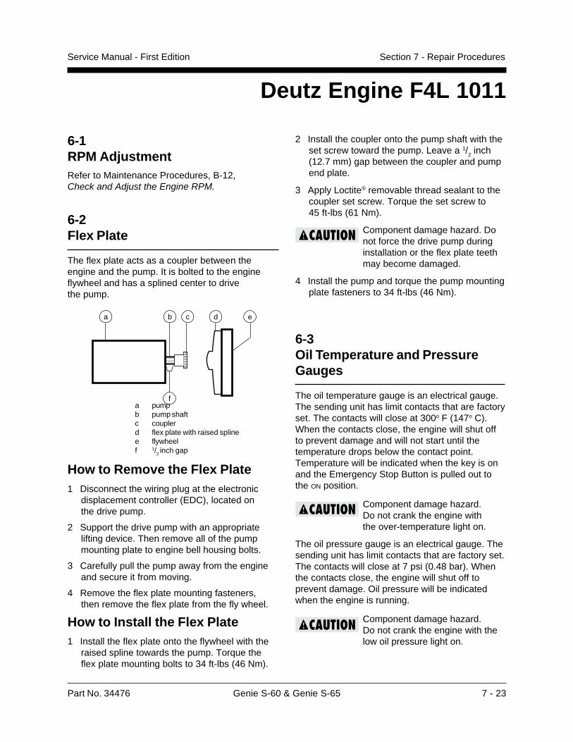
Part No. 34476 Genie S-60 & Genie S-65 7 - 23
Service Manual - First Edition Section 7 - Repair Procedures
6-1RPM AdjustmentRefer to Maintenance Procedures, B-12,Check and Adjust the Engine RPM.
6-2Flex Plate
The flex plate acts as a coupler between theengine and the pump. It is bolted to the engineflywheel and has a splined center to drivethe pump.
a pumpb pump shaftc couplerd flex plate with raised splinee flywheelf 1/2 inch gap
How to Remove the Flex Plate1 Disconnect the wiring plug at the electronic
displacement controller (EDC), located onthe drive pump.
2 Support the drive pump with an appropriatelifting device. Then remove all of the pumpmounting plate to engine bell housing bolts.
3 Carefully pull the pump away from the engineand secure it from moving.
4 Remove the flex plate mounting fasteners,then remove the flex plate from the fly wheel.
How to Install the Flex Plate1 Install the flex plate onto the flywheel with the
raised spline towards the pump. Torque theflex plate mounting bolts to 34 ft-lbs (46 Nm).
Deutz Engine F4L 1011
2 Install the coupler onto the pump shaft with theset screw toward the pump. Leave a 1/
2 inch
(12.7 mm) gap between the coupler and pumpend plate.
3 Apply Loctite® removable thread sealant to thecoupler set screw. Torque the set screw to45 ft-lbs (61 Nm).
Component damage hazard. Donot force the drive pump duringinstallation or the flex plate teethmay become damaged.
4 Install the pump and torque the pump mountingplate fasteners to 34 ft-lbs (46 Nm).
6-3Oil Temperature and PressureGauges
The oil temperature gauge is an electrical gauge.The sending unit has limit contacts that are factoryset. The contacts will close at 300o F (147o C).When the contacts close, the engine will shut offto prevent damage and will not start until thetemperature drops below the contact point.Temperature will be indicated when the key is onand the Emergency Stop Button is pulled out tothe ON position.
Component damage hazard.Do not crank the engine withthe over-temperature light on.
The oil pressure gauge is an electrical gauge. Thesending unit has limit contacts that are factory set.The contacts will close at 7 psi (0.48 bar). Whenthe contacts close, the engine will shut off toprevent damage. Oil pressure will be indicatedwhen the engine is running.
Component damage hazard.Do not crank the engine with thelow oil pressure light on.
a b c d e
f
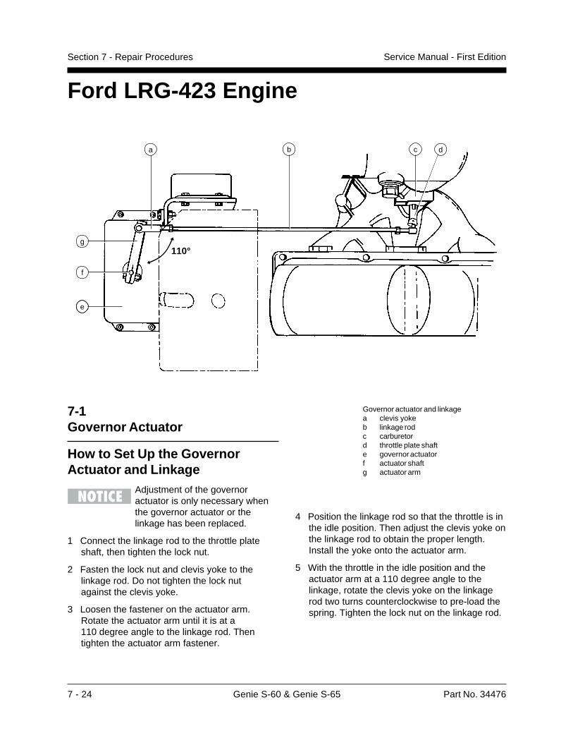
7 - 24 Genie S-60 & Genie S-65 Part No. 34476
Service Manual - First EditionSection 7 - Repair Procedures
e
b c
f
g
7-1Governor Actuator
How to Set Up the GovernorActuator and Linkage
Adjustment of the governoractuator is only necessary whenthe governor actuator or thelinkage has been replaced.
1 Connect the linkage rod to the throttle plateshaft, then tighten the lock nut.
2 Fasten the lock nut and clevis yoke to thelinkage rod. Do not tighten the lock nutagainst the clevis yoke.
3 Loosen the fastener on the actuator arm.Rotate the actuator arm until it is at a110 degree angle to the linkage rod. Thentighten the actuator arm fastener.
Governor actuator and linkagea clevis yokeb linkage rodc carburetord throttle plate shafte governor actuatorf actuator shaftg actuator arm
4 Position the linkage rod so that the throttle is inthe idle position. Then adjust the clevis yoke onthe linkage rod to obtain the proper length.Install the yoke onto the actuator arm.
5 With the throttle in the idle position and theactuator arm at a 110 degree angle to thelinkage, rotate the clevis yoke on the linkagerod two turns counterclockwise to pre-load thespring. Tighten the lock nut on the linkage rod.
d
110°
a
Ford LRG-423 Engine
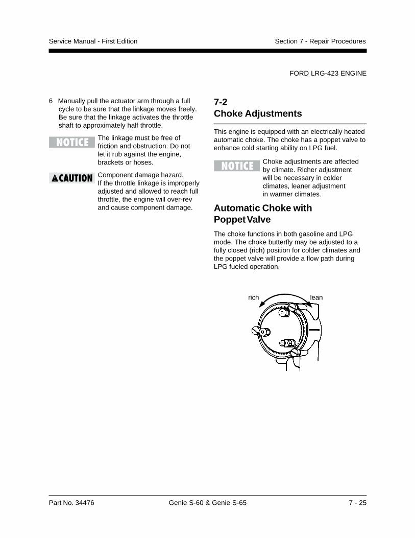
Part No. 34476 Genie S-60 & Genie S-65 7 - 25
Service Manual - First Edition Section 7 - Repair Procedures
6 Manually pull the actuator arm through a fullcycle to be sure that the linkage moves freely.Be sure that the linkage activates the throttleshaft to approximately half throttle.
The linkage must be free offriction and obstruction. Do notlet it rub against the engine,brackets or hoses.
Component damage hazard.If the throttle linkage is improperlyadjusted and allowed to reach fullthrottle, the engine will over-revand cause component damage.
FORD LRG-423 ENGINE
7-2Choke Adjustments
This engine is equipped with an electrically heatedautomatic choke. The choke has a poppet valve toenhance cold starting ability on LPG fuel.
Choke adjustments are affectedby climate. Richer adjustmentwill be necessary in colderclimates, leaner adjustmentin warmer climates.
Automatic Choke withPoppet ValveThe choke functions in both gasoline and LPGmode. The choke butterfly may be adjusted to afully closed (rich) position for colder climates andthe poppet valve will provide a flow path duringLPG fueled operation.
rich lean
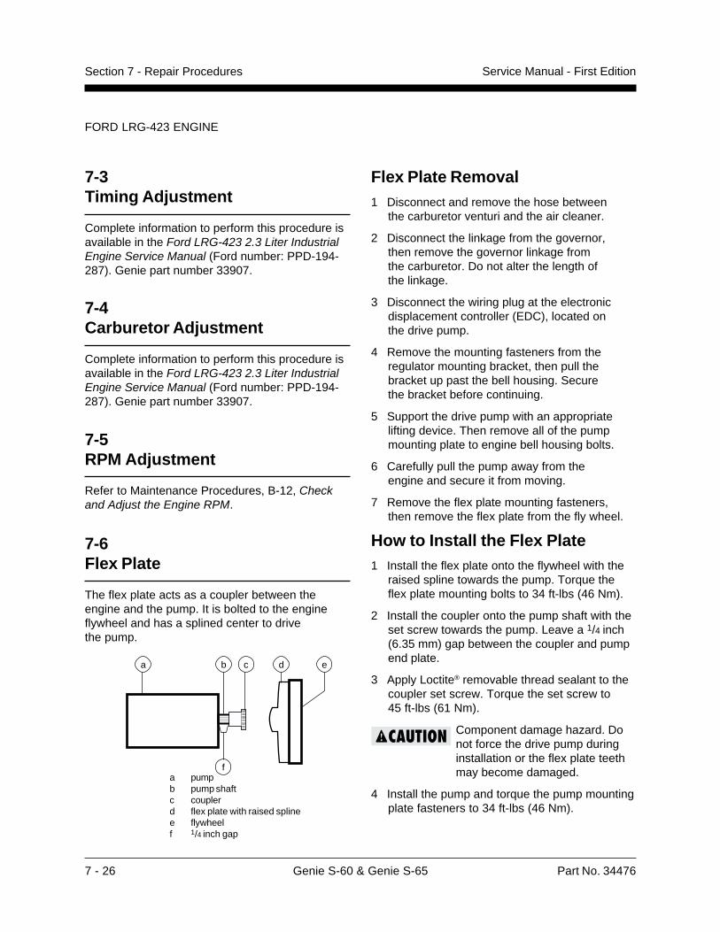
7 - 26 Genie S-60 & Genie S-65 Part No. 34476
Service Manual - First EditionSection 7 - Repair Procedures
Flex Plate Removal1 Disconnect and remove the hose between
the carburetor venturi and the air cleaner.
2 Disconnect the linkage from the governor,then remove the governor linkage fromthe carburetor. Do not alter the length ofthe linkage.
3 Disconnect the wiring plug at the electronicdisplacement controller (EDC), located onthe drive pump.
4 Remove the mounting fasteners from theregulator mounting bracket, then pull thebracket up past the bell housing. Securethe bracket before continuing.
5 Support the drive pump with an appropriatelifting device. Then remove all of the pumpmounting plate to engine bell housing bolts.
6 Carefully pull the pump away from theengine and secure it from moving.
7 Remove the flex plate mounting fasteners,then remove the flex plate from the fly wheel.
How to Install the Flex Plate1 Install the flex plate onto the flywheel with the
raised spline towards the pump. Torque theflex plate mounting bolts to 34 ft-lbs (46 Nm).
2 Install the coupler onto the pump shaft with theset screw towards the pump. Leave a 1/4 inch(6.35 mm) gap between the coupler and pumpend plate.
3 Apply Loctite® removable thread sealant to thecoupler set screw. Torque the set screw to45 ft-lbs (61 Nm).
Component damage hazard. Donot force the drive pump duringinstallation or the flex plate teethmay become damaged.
4 Install the pump and torque the pump mountingplate fasteners to 34 ft-lbs (46 Nm).
FORD LRG-423 ENGINE
7-3Timing Adjustment
Complete information to perform this procedure isavailable in the Ford LRG-423 2.3 Liter IndustrialEngine Service Manual (Ford number: PPD-194-287). Genie part number 33907.
7-4Carburetor Adjustment
Complete information to perform this procedure isavailable in the Ford LRG-423 2.3 Liter IndustrialEngine Service Manual (Ford number: PPD-194-287). Genie part number 33907.
7-5RPM Adjustment
Refer to Maintenance Procedures, B-12, Checkand Adjust the Engine RPM.
7-6Flex Plate
The flex plate acts as a coupler between theengine and the pump. It is bolted to the engineflywheel and has a splined center to drivethe pump.
a pumpb pump shaftc couplerd flex plate with raised splinee flywheelf 1/4 inch gap
a b c d e
f

Part No. 34476 Genie S-60 & Genie S-65 7 - 27
Service Manual - First Edition Section 7 - Repair Procedures
7-8Vacuum Switch
How to Test the Vacuum Switch
a ohmmeterb common terminal (SOL.)c vacuum switchd normally open terminal (ING.)
1 Connect the leads from an ohmmeter orcontinuity tester to the common and normallyopen terminals.
Result: There should be no continuity(infinite �).
2 Apply mild suction to the vacuum port.
Result: The switch should close and show fullcontinuity (zero �).
Component damage hazard.Do not short the vacuum switchterminals to ground.
FORD LRG-423 ENGINE
7-7Water Temperature and OilPressure Gauges
The water temperature gauge is an electricalgauge. The sending unit has limit contacts that arefactory set. The contacts will close at 230o F(109o C). When the contacts close, the engine willshut off to prevent damage and will not start untilthe temperature drops below the contact point.Temperature will be indicated when the key is onand the Emergency Stop Button is pulled out tothe ON position.
Component damage hazard.Do not crank the engine withthe over-temperature light on.
The oil pressure gauge is an electrical gauge. Thesending unit has limit contacts that are factory set.The contacts will close at 8 psi (0.55 bar). Whenthe contacts close, the engine will shut off toprevent damage. Oil pressure will be indicatedwhen the engine is running.
Component damage hazard.Do not crank the engine with thelow oil pressure light on.
a b
cd
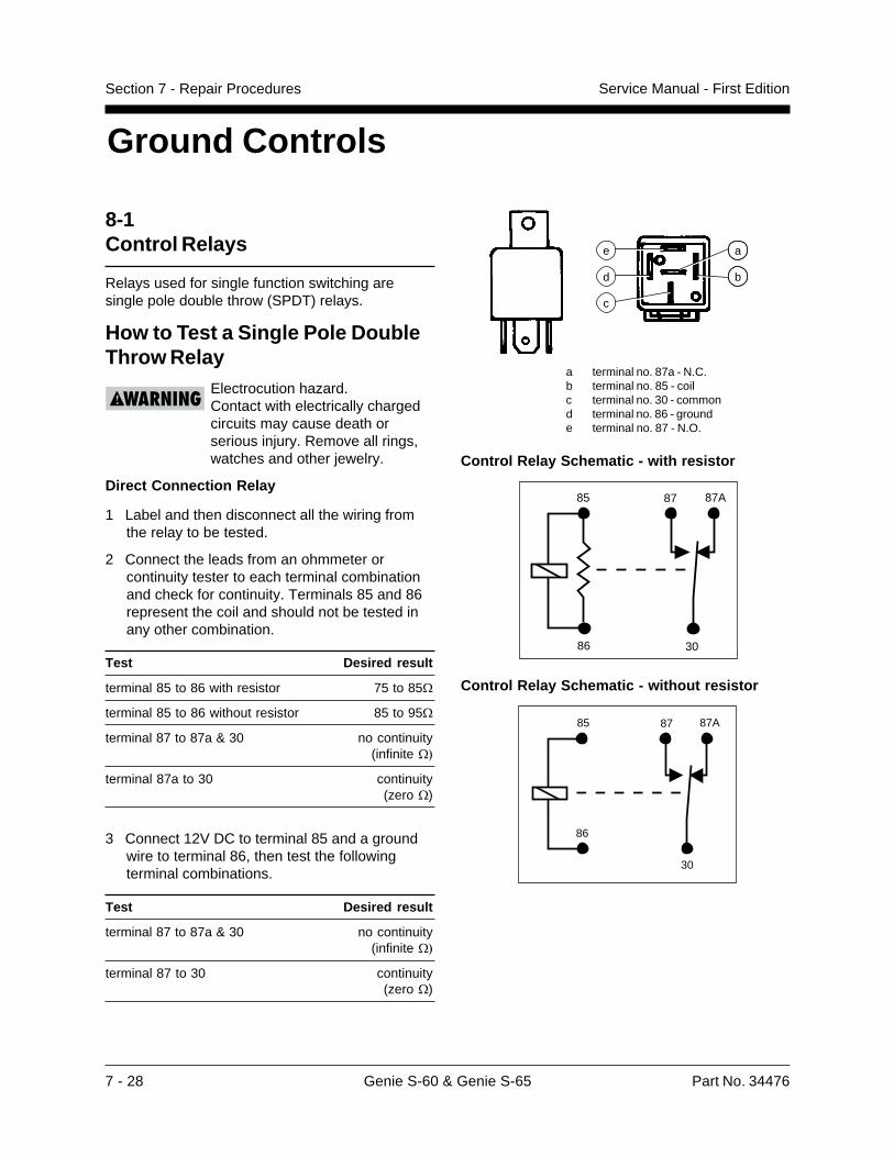
7 - 28 Genie S-60 & Genie S-65 Part No. 34476
Service Manual - First EditionSection 7 - Repair Procedures
Ground Controls
8-1Control Relays
Relays used for single function switching aresingle pole double throw (SPDT) relays.
How to Test a Single Pole DoubleThrow Relay
Electrocution hazard.Contact with electrically chargedcircuits may cause death orserious injury. Remove all rings,watches and other jewelry.
Direct Connection Relay
1 Label and then disconnect all the wiring fromthe relay to be tested.
2 Connect the leads from an ohmmeter orcontinuity tester to each terminal combinationand check for continuity. Terminals 85 and 86represent the coil and should not be tested inany other combination.
Test Desired result
terminal 85 to 86 with resistor 75 to 85�
terminal 85 to 86 without resistor 85 to 95�
terminal 87 to 87a & 30 no continuity(infinite ��
terminal 87a to 30 continuity(zero �)
3 Connect 12V DC to terminal 85 and a groundwire to terminal 86, then test the followingterminal combinations.
Test Desired result
terminal 87 to 87a & 30 no continuity(infinite ��
terminal 87 to 30 continuity(zero �)
d
e
c
a
b
a terminal no. 87a - N.C.b terminal no. 85 - coilc terminal no. 30 - commond terminal no. 86 - grounde terminal no. 87 - N.O.
Control Relay Schematic - with resistor
85
86
87 87A
30
Control Relay Schematic - without resistor
85
86
87 87A
30
Part No. 34476 Genie S-60 & Genie S-65 7 - 29
Service Manual - First Edition Section 7 - Repair Procedures
GROUND CONTROLS
8-2Toggle Switches
See 1-5, Toggle Switches.
8-3Wago® Components
How to Remove a Wago®
ComponentElectrocution hazard.Contact with electrically chargedcircuits may cause death orserious injury. Remove all rings,watches and other jewelry.
A small screwdriver is providedand should be used whenremoving a Wago® component.This screwdriver is located in theoperator’s manual storage box inthe platform.
1 Label the wiring from the component to beremoved.
2 Use the provided screwdriver to push in andrelease the wire from the component.
3 Locate the removal tab on the bottom or topside of the component.
4 Use the provided screwdriver to gently pry upon the tab of the component and remove it.
8-4Resistors
How to Test the ResistorThe resistor is used to maintain proper control ofboom function speeds. A 10 ohm resistor reducesvoltage to all the boom function switches.
Refer to the schematic legends forresistor locations and values.
1 Turn the key switch to the OFF position.
2 Disconnect either end of one of the wiresconnected to the resistor to be tested.
3 Connect the leads from an ohmmeter to eachend or wiring of the resistor being tested.
4 Compare the ohmmeter reading with theresistance rating printed on the resistor.
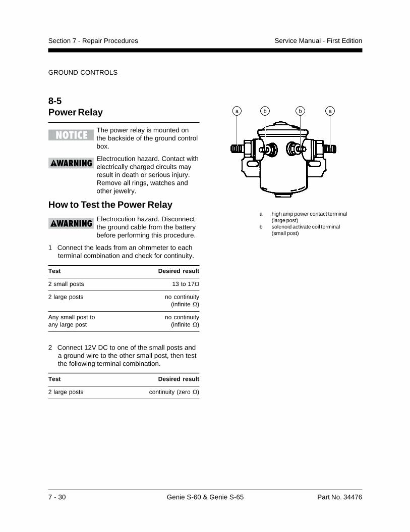
7 - 30 Genie S-60 & Genie S-65 Part No. 34476
Service Manual - First EditionSection 7 - Repair Procedures
GROUND CONTROLS
8-5Power Relay
The power relay is mounted onthe backside of the ground controlbox.
Electrocution hazard. Contact withelectrically charged circuits mayresult in death or serious injury.Remove all rings, watches andother jewelry.
How to Test the Power RelayElectrocution hazard. Disconnectthe ground cable from the batterybefore performing this procedure.
1 Connect the leads from an ohmmeter to eachterminal combination and check for continuity.
Test Desired result
2 small posts 13 to 17�
2 large posts no continuity(infinite �)
Any small post to no continuityany large post (infinite �)
2 Connect 12V DC to one of the small posts anda ground wire to the other small post, then testthe following terminal combination.
Test Desired result
2 large posts continuity (zero �)
a high amp power contact terminal(large post)
b solenoid activate coil terminal(small post)
a b ab
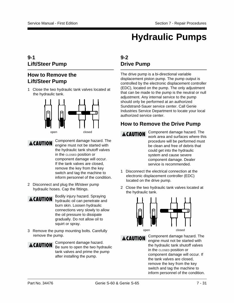
Part No. 34476 Genie S-60 & Genie S-65 7 - 31
Service Manual - First Edition Section 7 - Repair Procedures
Hydraulic Pumps
open closed
9-1Lift/Steer Pump
How to Remove theLift/Steer Pump1 Close the two hydraulic tank valves located at
the hydraulic tank.
Component damage hazard. Theengine must not be started withthe hydraulic tank shutoff valvesin the CLOSED position orcomponent damage will occur.If the tank valves are closed,remove the key from the keyswitch and tag the machine toinform personnel of the condition.
2 Disconnect and plug the lift/steer pumphydraulic hoses. Cap the fittings.
Bodily injury hazard. Sprayinghydraulic oil can penetrate andburn skin. Loosen hydraulicconnections very slowly to allowthe oil pressure to dissipategradually. Do not allow oil tosquirt or spray.
3 Remove the pump mounting bolts. Carefullyremove the pump.
Component damage hazard.Be sure to open the two hydraulictank valves and prime the pumpafter installing the pump.
9-2Drive Pump
The drive pump is a bi-directional variabledisplacement piston pump. The pump output iscontrolled by the electronic displacement controller(EDC), located on the pump. The only adjustmentthat can be made to the pump is the neutral or nulladjustment. Any internal service to the pumpshould only be performed at an authorizedSundstrand-Sauer service center. Call GenieIndustries Service Department to locate your localauthorized service center.
How to Remove the Drive PumpComponent damage hazard. Thework area and surfaces where thisprocedure will be performed mustbe clean and free of debris thatcould get into the hydraulicsystem and cause severecomponent damage. Dealerservice is recommended.
1 Disconnect the electrical connection at theelectronic displacement controller (EDC)located on the drive pump.
2 Close the two hydraulic tank valves located atthe hydraulic tank.
Component damage hazard. Theengine must not be started withthe hydraulic tank shutoff valvesin the CLOSED position orcomponent damage will occur. Ifthe tank valves are closed,remove the key from the keyswitch and tag the machine toinform personnel of the condition.
open closed

7 - 32 Genie S-60 & Genie S-65 Part No. 34476
Service Manual - First EditionSection 7 - Repair Procedures
HYDRAULIC PUMPS
3 Tag and disconnect the hydraulic hoses fromthe pumps and plug them.
Bodily injury hazard. Sprayinghydraulic oil can penetrate andburn skin. Loosen hydraulicconnections very slowly to allowthe oil pressure to dissipategradually. Do not allow oil tosquirt or spray.
4 Support the pump and remove the twodrive pump mounting bolts. Carefullyremove the pump.
Component damage hazard.Be sure to open the two hydraulictank valves and prime the pumpafter installing the pump.
How to Prime the Pump1 Connect a 0 to 600 psi (0 to 41 bar) pressure
gauge to the test port on the drive pump.
2 Gasoline/LPG models: Disconnect theelectrical connector in the engine wiringharness between the precision governor andthe ignition coil. The plug connector is locatedunder the air cleaner.
Electrocution hazard.Contact with electrically chargedcircuits may cause death orserious injury. Remove all rings,watches and other jewelry.
Deutz Diesel models: Hold the manual fuelshutoff valve counterclockwise to the CLOSED
position.
3 Crank the engine with the starter motor for15 seconds, wait 15 seconds, then crank theengine an additional 15 seconds or until thepressure reaches 320 psi (22 bar).
4 Connect the wiring and start the engine fromthe ground controls. Check for hydraulic leaks.
Part No. 34476 Genie S-60 & Genie S-65 7 - 33
Service Manual - First Edition Section 7 - Repair Procedures
This page intentionally left blank.
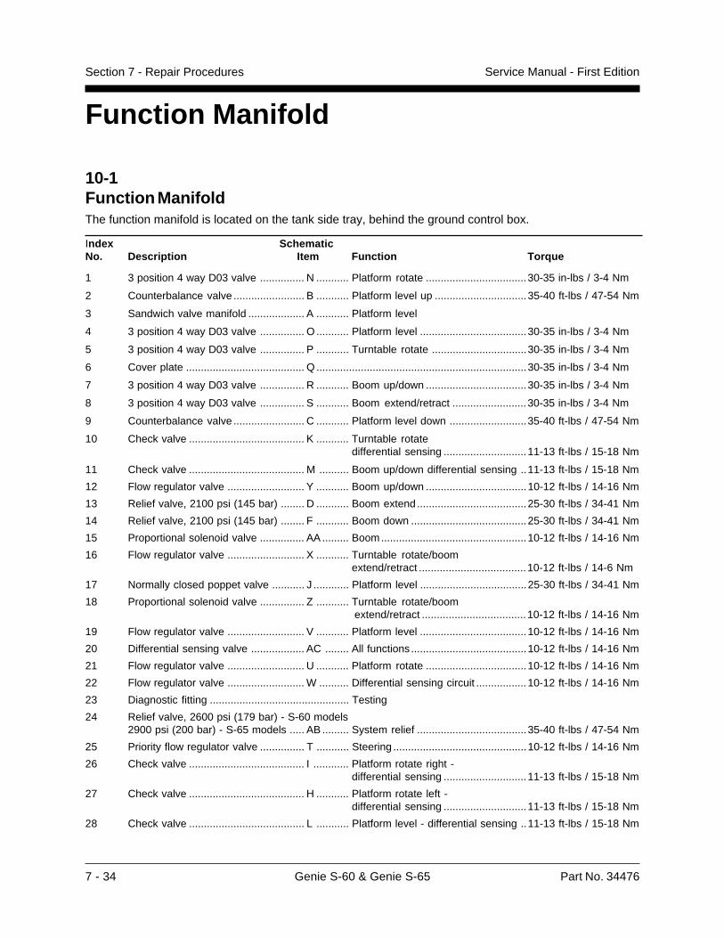
7 - 34 Genie S-60 & Genie S-65 Part No. 34476
Service Manual - First EditionSection 7 - Repair Procedures
Function Manifold
10-1Function ManifoldThe function manifold is located on the tank side tray, behind the ground control box.
Index SchematicNo. Description Item Function Torque
1 3 position 4 way D03 valve ............... N ........... Platform rotate ..................................30-35 in-lbs / 3-4 Nm
2 Counterbalance valve ........................ B ........... Platform level up ...............................35-40 ft-lbs / 47-54 Nm
3 Sandwich valve manifold ................... A ........... Platform level
4 3 position 4 way D03 valve ............... O ........... Platform level ....................................30-35 in-lbs / 3-4 Nm
5 3 position 4 way D03 valve ............... P ........... Turntable rotate ................................30-35 in-lbs / 3-4 Nm
6 Cover plate ........................................ Q .......................................................................30-35 in-lbs / 3-4 Nm
7 3 position 4 way D03 valve ............... R ........... Boom up/down ..................................30-35 in-lbs / 3-4 Nm
8 3 position 4 way D03 valve ............... S ........... Boom extend/retract .........................30-35 in-lbs / 3-4 Nm
9 Counterbalance valve ........................ C ........... Platform level down ..........................35-40 ft-lbs / 47-54 Nm
10 Check valve ....................................... K ........... Turntable rotatedifferential sensing ............................11-13 ft-lbs / 15-18 Nm
11 Check valve ....................................... M .......... Boom up/down differential sensing ..11-13 ft-lbs / 15-18 Nm
12 Flow regulator valve .......................... Y ........... Boom up/down ..................................10-12 ft-lbs / 14-16 Nm
13 Relief valve, 2100 psi (145 bar) ........ D ........... Boom extend.....................................25-30 ft-lbs / 34-41 Nm
14 Relief valve, 2100 psi (145 bar) ........ F ........... Boom down .......................................25-30 ft-lbs / 34-41 Nm
15 Proportional solenoid valve ............... AA ......... Boom.................................................10-12 ft-lbs / 14-16 Nm
16 Flow regulator valve .......................... X ........... Turntable rotate/boomextend/retract ....................................10-12 ft-lbs / 14-6 Nm
17 Normally closed poppet valve ........... J ............ Platform level ....................................25-30 ft-lbs / 34-41 Nm
18 Proportional solenoid valve ............... Z ........... Turntable rotate/boomextend/retract ...................................10-12 ft-lbs / 14-16 Nm
19 Flow regulator valve .......................... V ........... Platform level ....................................10-12 ft-lbs / 14-16 Nm
20 Differential sensing valve .................. AC ........ All functions .......................................10-12 ft-lbs / 14-16 Nm
21 Flow regulator valve .......................... U ........... Platform rotate ..................................10-12 ft-lbs / 14-16 Nm
22 Flow regulator valve .......................... W .......... Differential sensing circuit .................10-12 ft-lbs / 14-16 Nm
23 Diagnostic fitting ............................................... Testing
24 Relief valve, 2600 psi (179 bar) - S-60 models2900 psi (200 bar) - S-65 models ..... AB ......... System relief .....................................35-40 ft-lbs / 47-54 Nm
25 Priority flow regulator valve ............... T ........... Steering .............................................10-12 ft-lbs / 14-16 Nm
26 Check valve ....................................... I ............ Platform rotate right -differential sensing ............................11-13 ft-lbs / 15-18 Nm
27 Check valve ....................................... H ........... Platform rotate left -differential sensing ............................11-13 ft-lbs / 15-18 Nm
28 Check valve ....................................... L ........... Platform level - differential sensing ..11-13 ft-lbs / 15-18 Nm
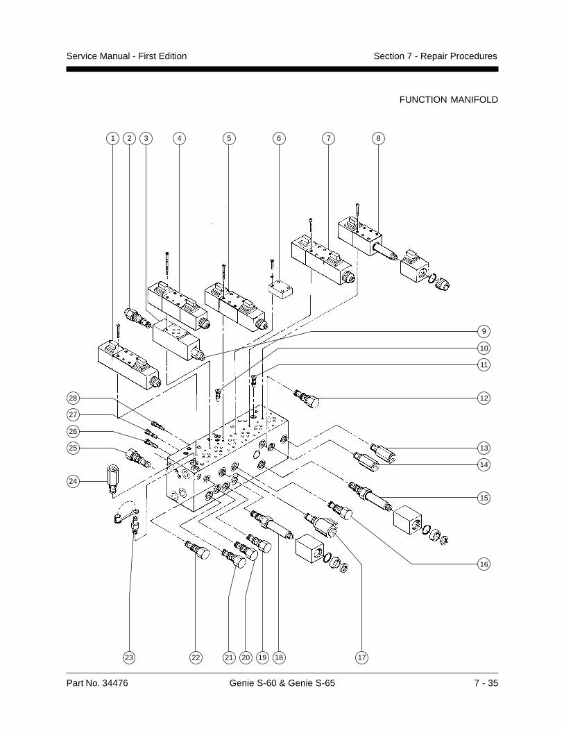
Part No. 34476 Genie S-60 & Genie S-65 7 - 35
Service Manual - First Edition Section 7 - Repair Procedures
FUNCTION MANIFOLD
21
14
23 22 1819
24
25
20
16
26
17
8
9
73 4 5
13
28
10
6
12
27
11
15
21
7 - 36 Genie S-60 & Genie S-65 Part No. 34476
Service Manual - First EditionSection 7 - Repair Procedures
10-2Valve Adjustments -Function Manifold
How to Adjust the MainRelief Valve
Perform this procedure with theboom in the stowed position.
1 Connect a 0 to 5000 psi (0 to 345 bar) pressuregauge to the test port (item 23) on the functionmanifold.
2 Start the engine from the ground controls.
3 Hold the retract switch with the boom fullyretracted, and observe the pressure reading onthe pressure gauge.
4 Turn the engine off. Use a wrench to hold therelief valve and remove the cap(item 24, function manifold).
5 Adjust the internal hex socket. Turn it clockwiseto increase the pressure or counterclockwise todecrease the pressure. Then install the reliefvalve cap.
Tip-over hazard. Do not adjustthe relief valves higher thanrecommended.
6 Restart the engine. Hold the retract switch withthe boom fully retracted, and recheck the valvepressure.
Main relief valve specifications
Pressure S-60 S-652600 psi 2900 psi179 bar 200 bar
FUNCTION MANIFOLD
How to Adjust the Boom DownRelief Valve
Perform this procedure with theboom in the stowed position.
1 Connect a 0 to 5000 psi (0 to 345 bar) pressuregauge to the test port (item 23) on the functionmanifold.
2 Start the engine from the ground controls.
3 Hold the boom down switch with the boom fullylowered, and observe the pressure reading onthe pressure gauge.
4 Turn the engine off. Use a wrench to hold therelief valve and remove the cap(item 14, function manifold).
5 Adjust the internal hex socket. Turn it clockwiseto increase the pressure or counterclockwise todecrease the pressure. Then install the reliefvalve cap.
Tip-over hazard. Do not adjustthe relief valves higher thanrecommended.
6 Restart the engine. Hold the boom down switchwith the boom fully lowered and recheck thevalve pressure.
Boom down relief valve specifications
Pressure 2100 psi145 bar
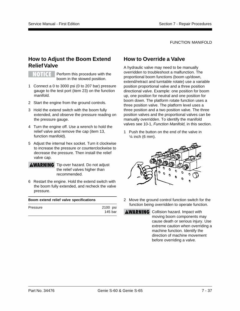
Part No. 34476 Genie S-60 & Genie S-65 7 - 37
Service Manual - First Edition Section 7 - Repair Procedures
How to Override a ValveA hydraulic valve may need to be manuallyoverridden to troubleshoot a malfunction. Theproportional boom functions (boom up/down,extend/retract and turntable rotate) use a variableposition proportional valve and a three positiondirectional valve. Example: one position for boomup, one position for neutral and one position forboom down. The platform rotate function uses athree position valve. The platform level uses athree position and a two position valve. The threeposition valves and the proportional valves can bemanually overridden. To identify the manifoldvalves see 10-1, Function Manifold, in this section.
1 Push the button on the end of the valve in¼ inch (6 mm).
2 Move the ground control function switch for thefunction being overridden to operate function.
Collision hazard. Impact withmoving boom components maycause death or serious injury. Useextreme caution when overriding amachine function. Identify thedirection of machine movementbefore overriding a valve.
FUNCTION MANIFOLD
How to Adjust the Boom ExtendRelief Valve
Perform this procedure with theboom in the stowed position.
1 Connect a 0 to 3000 psi (0 to 207 bar) pressuregauge to the test port (item 23) on the functionmanifold.
2 Start the engine from the ground controls.
3 Hold the extend switch with the boom fullyextended, and observe the pressure reading onthe pressure gauge.
4 Turn the engine off. Use a wrench to hold therelief valve and remove the cap (item 13,function manifold).
5 Adjust the internal hex socket. Turn it clockwiseto increase the pressure or counterclockwise todecrease the pressure. Then install the reliefvalve cap.
Tip-over hazard. Do not adjustthe relief valves higher thanrecommended.
6 Restart the engine. Hold the extend switch withthe boom fully extended, and recheck the valvepressure.
Boom extend relief valve specifications
Pressure 2100 psi145 bar

7 - 38 Genie S-60 & Genie S-65 Part No. 34476
Service Manual - First EditionSection 7 - Repair Procedures
FUNCTION MANIFOLD
How to Check the Resistanceof a Valve Coil1 Turn the key switch to the OFF position and
disconnect the wires from the valve coil to betested.
2 Connect the leads from an ohmmeter to thevalve coil terminals.
Valve coil specifications
Proportional solenoid valve 5�
3 position 4 way directional valve 4.5�
Normally closed poppet valve 7�
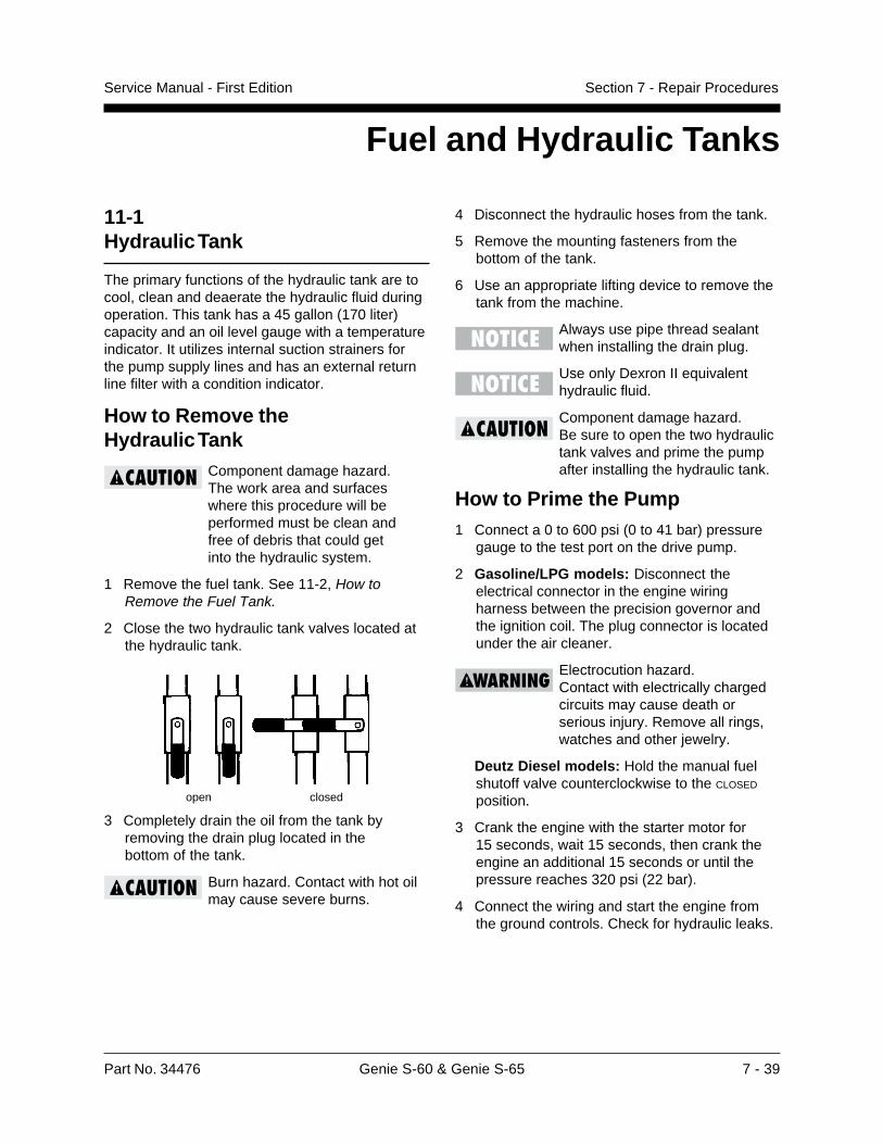
Part No. 34476 Genie S-60 & Genie S-65 7 - 39
Service Manual - First Edition Section 7 - Repair Procedures
11-1Hydraulic Tank
The primary functions of the hydraulic tank are tocool, clean and deaerate the hydraulic fluid duringoperation. This tank has a 45 gallon (170 liter)capacity and an oil level gauge with a temperatureindicator. It utilizes internal suction strainers forthe pump supply lines and has an external returnline filter with a condition indicator.
How to Remove theHydraulic Tank
Component damage hazard.The work area and surfaceswhere this procedure will beperformed must be clean andfree of debris that could getinto the hydraulic system.
1 Remove the fuel tank. See 11-2, How toRemove the Fuel Tank.
2 Close the two hydraulic tank valves located atthe hydraulic tank.
3 Completely drain the oil from the tank byremoving the drain plug located in thebottom of the tank.
Burn hazard. Contact with hot oilmay cause severe burns.
4 Disconnect the hydraulic hoses from the tank.
5 Remove the mounting fasteners from thebottom of the tank.
6 Use an appropriate lifting device to remove thetank from the machine.
Always use pipe thread sealantwhen installing the drain plug.
Use only Dexron II equivalenthydraulic fluid.
Component damage hazard.Be sure to open the two hydraulictank valves and prime the pumpafter installing the hydraulic tank.
How to Prime the Pump1 Connect a 0 to 600 psi (0 to 41 bar) pressure
gauge to the test port on the drive pump.
2 Gasoline/LPG models: Disconnect theelectrical connector in the engine wiringharness between the precision governor andthe ignition coil. The plug connector is locatedunder the air cleaner.
Electrocution hazard.Contact with electrically chargedcircuits may cause death orserious injury. Remove all rings,watches and other jewelry.
Deutz Diesel models: Hold the manual fuelshutoff valve counterclockwise to the CLOSED
position.
3 Crank the engine with the starter motor for15 seconds, wait 15 seconds, then crank theengine an additional 15 seconds or until thepressure reaches 320 psi (22 bar).
4 Connect the wiring and start the engine fromthe ground controls. Check for hydraulic leaks.
Fuel and Hydraulic Tanks
open closed
7 - 40 Genie S-60 & Genie S-65 Part No. 34476
Service Manual - First EditionSection 7 - Repair Procedures
FUEL AND HYDRAULIC TANKS
11-2Fuel Tank
How to Remove the Fuel TankExplosion hazard. Engine fuelsare combustible. Remove the fueltank in an open, well-ventilatedarea away from heaters, sparks,flames and lighted tobacco.Always have an approved fireextinguisher within easy reach.
Explosion hazard. Whentransferring fuel, connect agrounding wire between themachine and pump or container.
1 Turn the manual fuel shutoff valve to theCLOSED position.
2 Gasoline/LPG models: Disconnect, drain andplug the fuel hose.
Deutz Diesel models: Disconnect, drain andplug the supply and return fuel lines. Cap thefuel return fitting on the fuel tank.
3 Remove the mounting fasteners from thebottom of the tank.
4 Use an appropriate lifting device to remove thetank from the machine.
Clean the fuel tank and inspectfor rust and corrosion beforeinstalling.
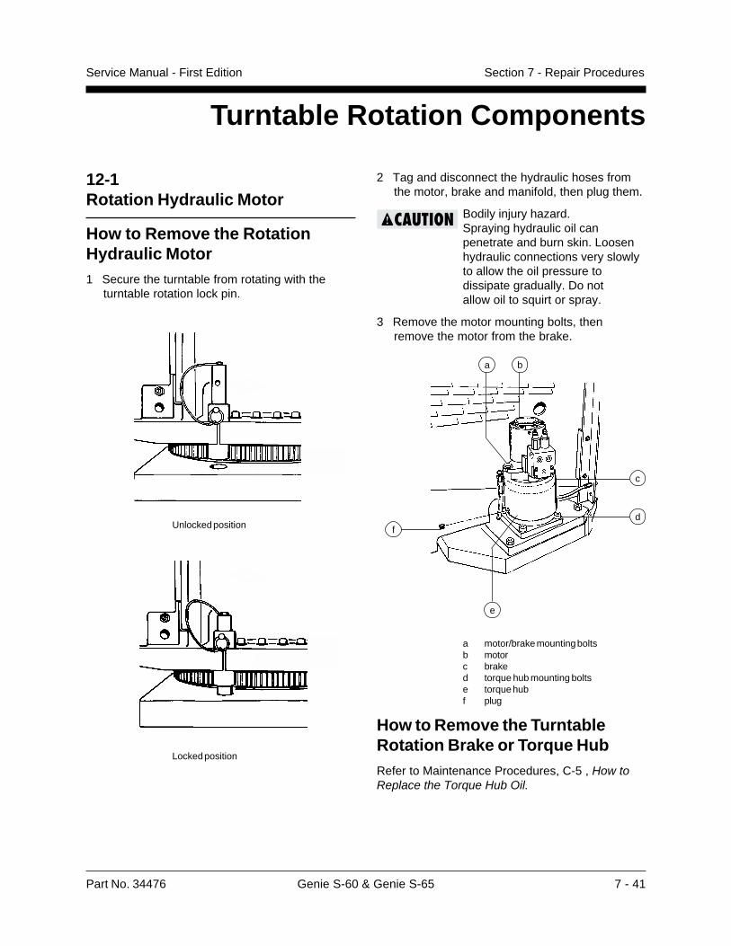
Part No. 34476 Genie S-60 & Genie S-65 7 - 41
Service Manual - First Edition Section 7 - Repair Procedures
2 Tag and disconnect the hydraulic hoses fromthe motor, brake and manifold, then plug them.
Bodily injury hazard.Spraying hydraulic oil canpenetrate and burn skin. Loosenhydraulic connections very slowlyto allow the oil pressure todissipate gradually. Do notallow oil to squirt or spray.
3 Remove the motor mounting bolts, thenremove the motor from the brake.
a motor/brake mounting boltsb motorc braked torque hub mounting boltse torque hubf plug
How to Remove the TurntableRotation Brake or Torque HubRefer to Maintenance Procedures, C-5 , How toReplace the Torque Hub Oil.
12-1Rotation Hydraulic Motor
How to Remove the RotationHydraulic Motor1 Secure the turntable from rotating with the
turntable rotation lock pin.
Unlocked position
Locked position
Turntable Rotation Components
ba
df
e
c
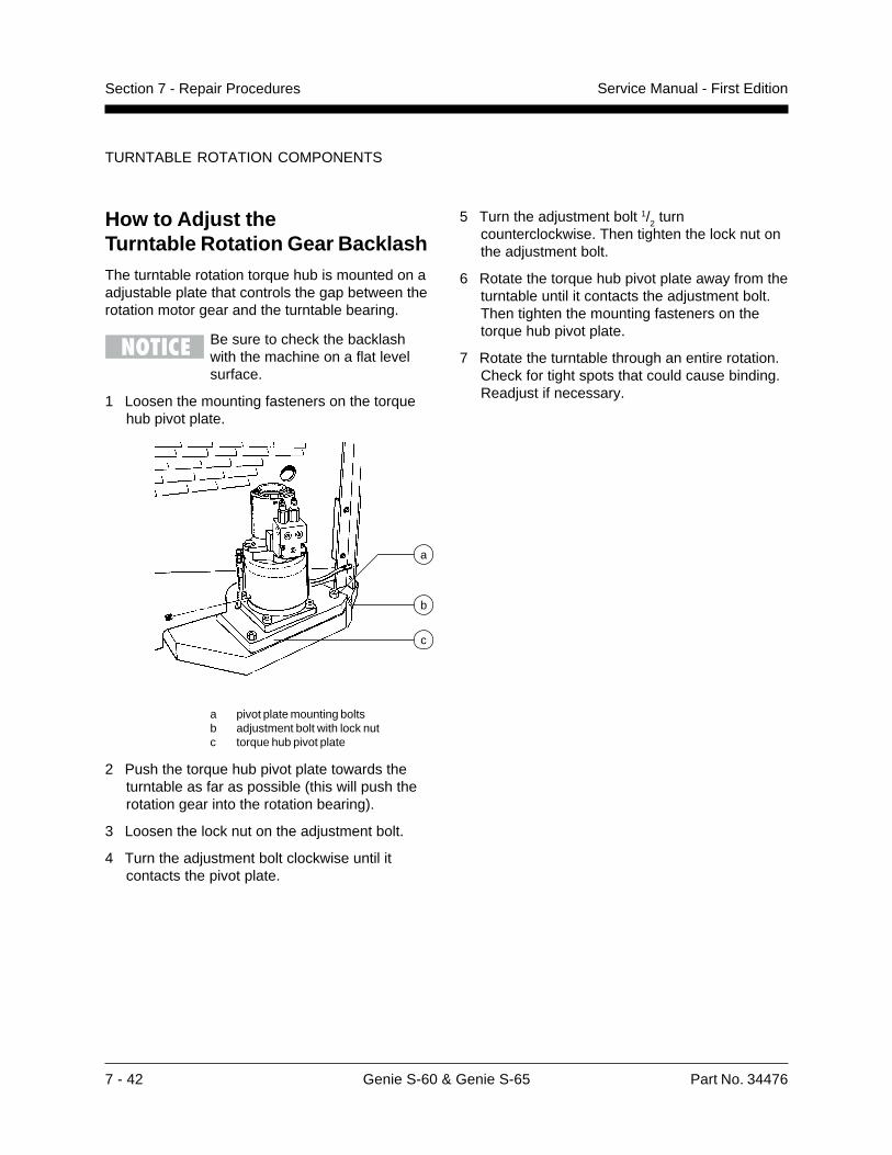
7 - 42 Genie S-60 & Genie S-65 Part No. 34476
Service Manual - First EditionSection 7 - Repair Procedures
How to Adjust theTurntable Rotation Gear BacklashThe turntable rotation torque hub is mounted on aadjustable plate that controls the gap between therotation motor gear and the turntable bearing.
Be sure to check the backlashwith the machine on a flat levelsurface.
1 Loosen the mounting fasteners on the torquehub pivot plate.
a pivot plate mounting boltsb adjustment bolt with lock nutc torque hub pivot plate
2 Push the torque hub pivot plate towards theturntable as far as possible (this will push therotation gear into the rotation bearing).
3 Loosen the lock nut on the adjustment bolt.
4 Turn the adjustment bolt clockwise until itcontacts the pivot plate.
a
b
c
5 Turn the adjustment bolt 1/2 turn
counterclockwise. Then tighten the lock nut onthe adjustment bolt.
6 Rotate the torque hub pivot plate away from theturntable until it contacts the adjustment bolt.Then tighten the mounting fasteners on thetorque hub pivot plate.
7 Rotate the turntable through an entire rotation.Check for tight spots that could cause binding.Readjust if necessary.
TURNTABLE ROTATION COMPONENTS
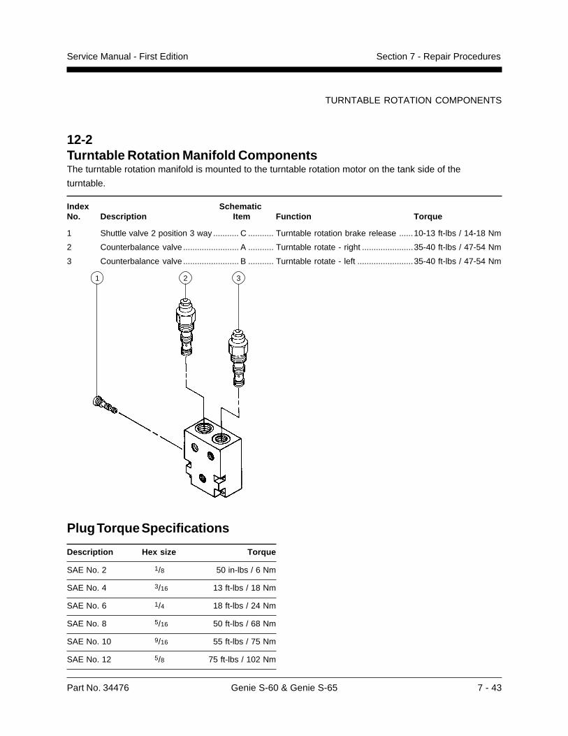
Part No. 34476 Genie S-60 & Genie S-65 7 - 43
Service Manual - First Edition Section 7 - Repair Procedures
12-2Turntable Rotation Manifold ComponentsThe turntable rotation manifold is mounted to the turntable rotation motor on the tank side of the
turntable.
Index SchematicNo. Description Item Function Torque
1 Shuttle valve 2 position 3 way ........... C ........... Turntable rotation brake release ......10-13 ft-lbs / 14-18 Nm
2 Counterbalance valve ........................ A ........... Turntable rotate - right ......................35-40 ft-lbs / 47-54 Nm
3 Counterbalance valve ........................ B ........... Turntable rotate - left ........................35-40 ft-lbs / 47-54 Nm
321
Plug Torque Specifications
Description Hex size Torque
SAE No. 2 1/8 50 in-lbs / 6 Nm
SAE No. 4 3/16 13 ft-lbs / 18 Nm
SAE No. 6 1/4 18 ft-lbs / 24 Nm
SAE No. 8 5/16 50 ft-lbs / 68 Nm
SAE No. 10 9/16 55 ft-lbs / 75 Nm
SAE No. 12 5/8 75 ft-lbs / 102 Nm
TURNTABLE ROTATION COMPONENTS
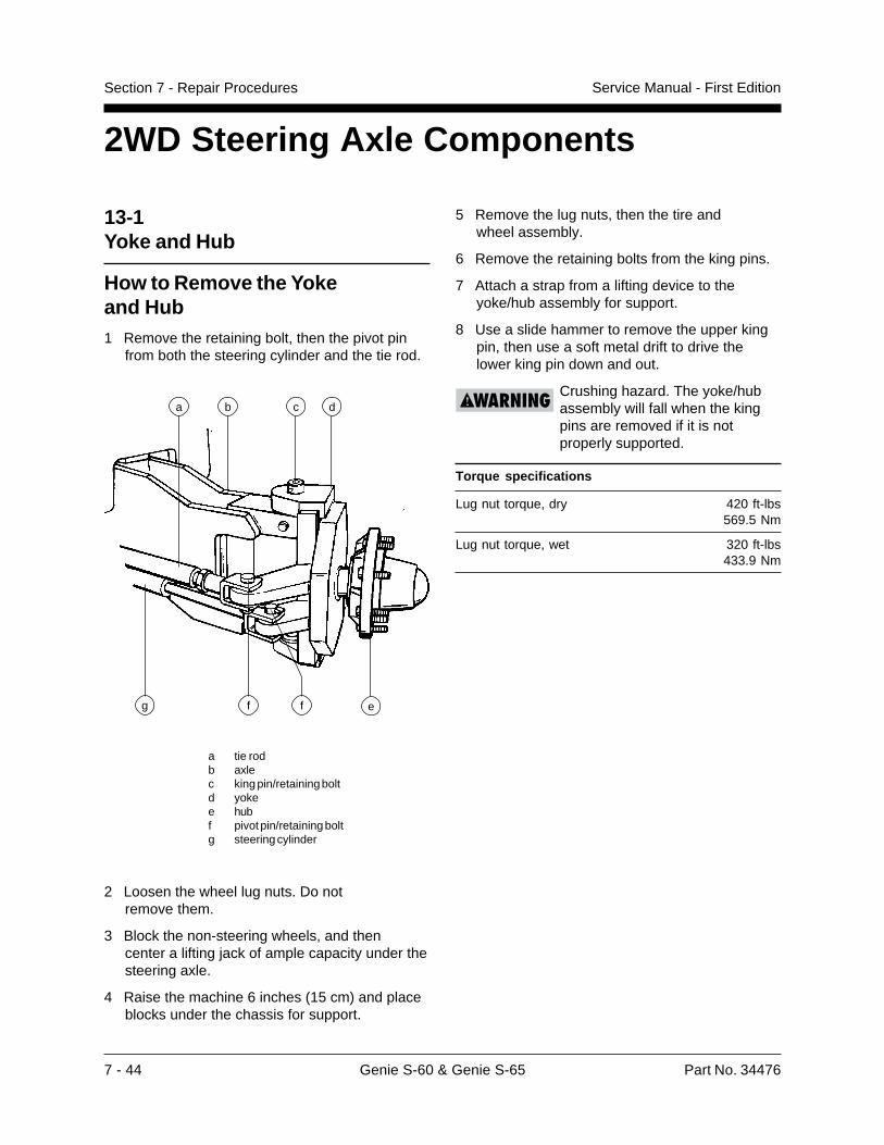
7 - 44 Genie S-60 & Genie S-65 Part No. 34476
Service Manual - First EditionSection 7 - Repair Procedures
5 Remove the lug nuts, then the tire andwheel assembly.
6 Remove the retaining bolts from the king pins.
7 Attach a strap from a lifting device to theyoke/hub assembly for support.
8 Use a slide hammer to remove the upper kingpin, then use a soft metal drift to drive thelower king pin down and out.
Crushing hazard. The yoke/hubassembly will fall when the kingpins are removed if it is notproperly supported.
Torque specifications
Lug nut torque, dry 420 ft-lbs569.5 Nm
Lug nut torque, wet 320 ft-lbs433.9 Nm
2WD Steering Axle Components
13-1Yoke and Hub
How to Remove the Yokeand Hub1 Remove the retaining bolt, then the pivot pin
from both the steering cylinder and the tie rod.
a tie rodb axlec king pin/retaining boltd yokee hubf pivot pin/retaining boltg steering cylinder
2 Loosen the wheel lug nuts. Do notremove them.
3 Block the non-steering wheels, and thencenter a lifting jack of ample capacity under thesteering axle.
4 Raise the machine 6 inches (15 cm) and placeblocks under the chassis for support.
a b
e
d
fg
c
f
Part No. 34476 Genie S-60 & Genie S-65 7 - 45
Service Manual - First Edition Section 7 - Repair Procedures
How to Remove theHub and Bearings1 Loosen the wheel lug nuts. Do not remove
them.
2 Block the non-steering wheels and place alifting jack of ample capacity under the steeringaxle.
3 Raise the machine and place blocks underthe chassis for support.
4 Remove the lug nuts. Then remove the tireand wheel assembly.
5 Remove the dust cap, cotter pin andslotted nut.
6 Pull the hub off the spindle. The washer andouter bearing should fall loose from the hub.
7 Place the hub on a flat surface and gently prythe bearing seal out of the hub. Remove therear bearing.
How to Install theHub and Bearings
When replacing a wheel bearing,both the inner and outer bearingsincluding the pressed-in racesmust be replaced.
1 Be sure that both bearings are packedwith grease.
2 Place the large inner bearing into the rearof the hub.
3 Press the bearing seal evenly into the hubuntil it is flush.
4 Slide the hub onto the yoke spindle.
Component damage. Do notapply excessive force or damageto the lip of the seal may occur.
13-2Steering Cylinders
How to Remove aSteering CylinderThere are two identical steering cylinders thatwork in parallel. They are part of the samehydraulic circuit, but move in opposite directions.The tie rod maintains equal movement of the tires.Bushings are used at both ends of each steeringcylinder clevis.
1 Disconnect and plug the hydraulic hoses fromthe steering cylinder. Cap the fittings.
Bodily injury hazard. Sprayinghydraulic oil can penetrate andburn skin. Loosen hydraulicconnections very slowly to allowthe oil pressure to dissipategradually. Do not allow oil tosquirt or spray.
2 Remove the pin retaining fasteners. Thenremove the pivot pin from each end of thesteering cylinder.
3 Remove the steering cylinder.
2WD STEERING AXLE COMPONENTS
5 Place the outer bearing into the hub.
6 Install the washer and slotted nut.
7 Tighten the slotted nut to 35 foot-pounds(47 Nm).
8 Loosen the slotted nut, then re-tighten to8 foot-pounds (11 Nm).
9 Install a new cotter pin. Bend the cotter pinto lock it in.
10 Install the dust cap, then the tire and wheelassembly. Torque the wheel lug nuts to125 foot-pounds (169.5 Nm).
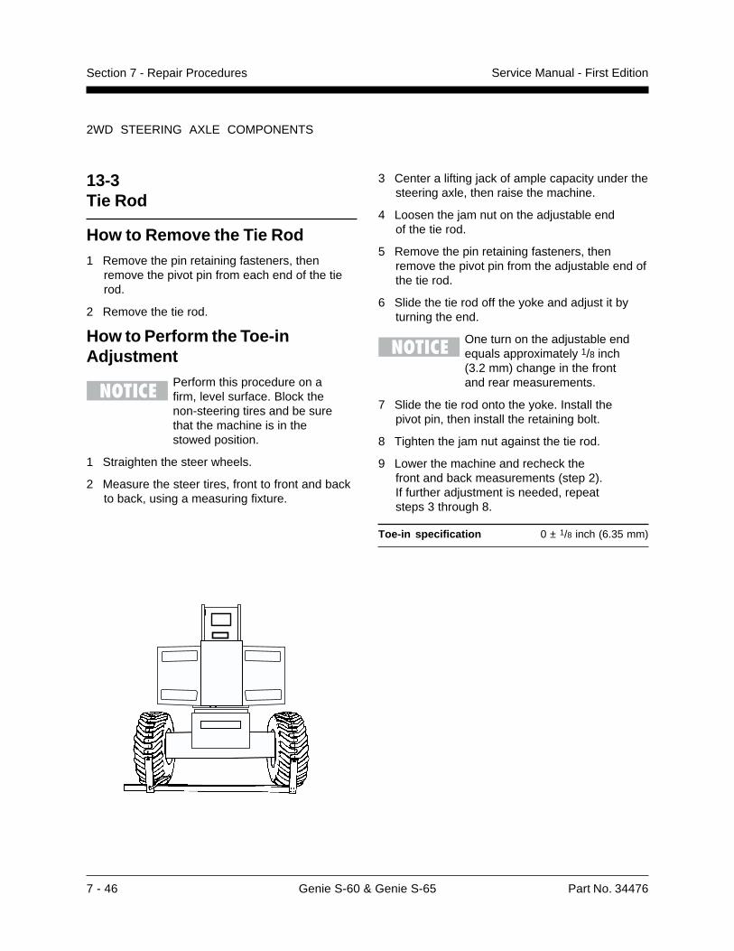
7 - 46 Genie S-60 & Genie S-65 Part No. 34476
Service Manual - First EditionSection 7 - Repair Procedures
2WD STEERING AXLE COMPONENTS
13-3Tie Rod
How to Remove the Tie Rod1 Remove the pin retaining fasteners, then
remove the pivot pin from each end of the tierod.
2 Remove the tie rod.
How to Perform the Toe-inAdjustment
Perform this procedure on afirm, level surface. Block thenon-steering tires and be surethat the machine is in thestowed position.
1 Straighten the steer wheels.
2 Measure the steer tires, front to front and backto back, using a measuring fixture.
3 Center a lifting jack of ample capacity under thesteering axle, then raise the machine.
4 Loosen the jam nut on the adjustable endof the tie rod.
5 Remove the pin retaining fasteners, thenremove the pivot pin from the adjustable end ofthe tie rod.
6 Slide the tie rod off the yoke and adjust it byturning the end.
One turn on the adjustable endequals approximately 1/8 inch(3.2 mm) change in the frontand rear measurements.
7 Slide the tie rod onto the yoke. Install thepivot pin, then install the retaining bolt.
8 Tighten the jam nut against the tie rod.
9 Lower the machine and recheck thefront and back measurements (step 2).If further adjustment is needed, repeatsteps 3 through 8.
Toe-in specification 0 ± 1/8 inch (6.35 mm)
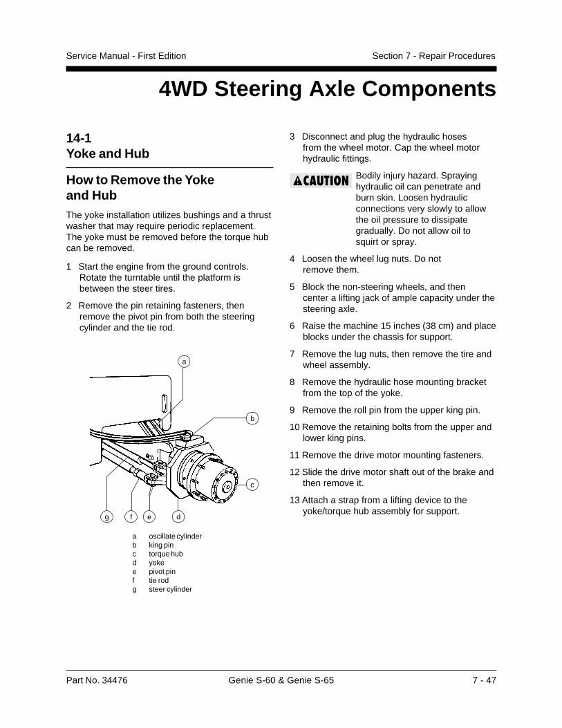
Part No. 34476 Genie S-60 & Genie S-65 7 - 47
Service Manual - First Edition Section 7 - Repair Procedures
3 Disconnect and plug the hydraulic hosesfrom the wheel motor. Cap the wheel motorhydraulic fittings.
Bodily injury hazard. Sprayinghydraulic oil can penetrate andburn skin. Loosen hydraulicconnections very slowly to allowthe oil pressure to dissipategradually. Do not allow oil tosquirt or spray.
4 Loosen the wheel lug nuts. Do notremove them.
5 Block the non-steering wheels, and thencenter a lifting jack of ample capacity under thesteering axle.
6 Raise the machine 15 inches (38 cm) and placeblocks under the chassis for support.
7 Remove the lug nuts, then remove the tire andwheel assembly.
8 Remove the hydraulic hose mounting bracketfrom the top of the yoke.
9 Remove the roll pin from the upper king pin.
10 Remove the retaining bolts from the upper andlower king pins.
11 Remove the drive motor mounting fasteners.
12 Slide the drive motor shaft out of the brake andthen remove it.
13 Attach a strap from a lifting device to theyoke/torque hub assembly for support.
4WD Steering Axle Components
a
b
c
d
14-1Yoke and Hub
How to Remove the Yokeand HubThe yoke installation utilizes bushings and a thrustwasher that may require periodic replacement.The yoke must be removed before the torque hubcan be removed.
1 Start the engine from the ground controls.Rotate the turntable until the platform isbetween the steer tires.
2 Remove the pin retaining fasteners, thenremove the pivot pin from both the steeringcylinder and the tie rod.
a oscillate cylinderb king pinc torque hubd yokee pivot pinf tie rodg steer cylinder
efg
7 - 48 Genie S-60 & Genie S-65 Part No. 34476
Service Manual - First EditionSection 7 - Repair Procedures
14 Use a slide hammer to remove the upper kingpin, then use a soft metal drift to drive thelower king pin down and out.
Crushing hazard. The yoke/torquehub assembly will fall when thelower king pin is removed if it isnot properly supported.
15 Place the yoke/torque hub assembly on a flatsurface with the torque hub down. Remove thebolts that secure the yoke to the torque hub.
Torque specifications
Lug nut - dry bolts 420 ft-lbs569.5 Nm
Lug nut - lubricated bolts 320 ft-lbs433.9 Nm
Torque hub mounting bolts 120 ft-lbs163 Nm
Drive motor mounting bolts 75 ft-lbs102 Nm
14-2Steering Cylinders
How to Remove aSteering CylinderThis procedure is the same as the 2WDprocedure. See repair procedure 13-2,How to Remove a Steering Cylinder.
4WD STEERING AXLE COMPONENTS
14-3Tie Rod
How to Remove the Tie RodThis procedure is the same as the 2WDprocedure. See Repair Procedure 13-3,How to Remove the Tie Rod.
How to Perform the Toe-inAdjustmentThis procedure is the same as the 2WDprocedure. See Repair Procedure 13-3,How to Perform the Toe-in Adjustment.
Part No. 34476 Genie S-60 & Genie S-65 7 - 49
Service Manual - First Edition Section 7 - Repair Procedures
15-1Oscillating AxleLock-out Cylinders
The oscillating axle cylinders extend and retractbetween the drive chassis and the oscillating axle.The cylinders are equipped with counterbalancevalves to prevent movement in the event of ahydraulic line failure. The valves are notadjustable.
How to Remove an OscillatingAxle Cylinder
This procedure requires specificrepair skills and a suitableworkshop. Attempting thisprocedure without these skillsand tools may result in death orserious injury and significantcomponent damage. Dealerservice is strongly recommended.
Perform this procedure on a firm,level surface with the boom inthe stowed position.
1 Rotate the boom until the boom is between thesteer tires.
2 Block the non-steering wheels, then center alifting jack between the steering wheels underthe axle pivot pin.
3 Raise the machine 6 inches (15 cm) and placeblocks under the drive chassis.
Oscillating Axle Components
4 Disconnect and plug the oscillating axlecylinder hydraulic hoses, and cap the cylinderfittings.
Bodily injury hazard. Sprayinghydraulic oil can penetrate andburn skin. Loosen hydraulicconnections very slowly to allowthe oil pressure to dissipategradually. Do not allow oil to squirtor spray.
5 Remove the pin retaining fasteners from bothpivot pins.
6 Attach a strap from a lifting device to thecylinder for support.
7 Use a soft metal drift to remove the pins.
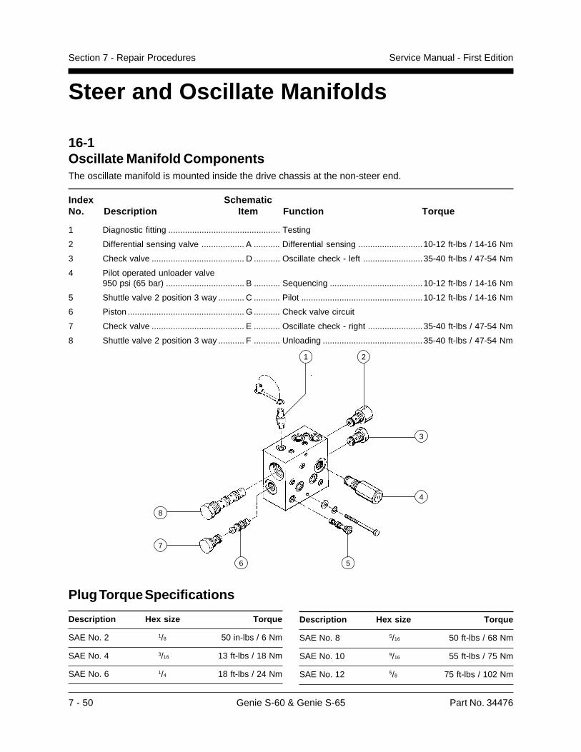
7 - 50 Genie S-60 & Genie S-65 Part No. 34476
Service Manual - First EditionSection 7 - Repair Procedures
16-1Oscillate Manifold ComponentsThe oscillate manifold is mounted inside the drive chassis at the non-steer end.
Index SchematicNo. Description Item Function Torque
1 Diagnostic fitting ............................................... Testing
2 Differential sensing valve .................. A ........... Differential sensing ...........................10-12 ft-lbs / 14-16 Nm
3 Check valve ....................................... D ........... Oscillate check - left .........................35-40 ft-lbs / 47-54 Nm
4 Pilot operated unloader valve950 psi (65 bar) ................................. B ........... Sequencing .......................................10-12 ft-lbs / 14-16 Nm
5 Shuttle valve 2 position 3 way ........... C ........... Pilot ...................................................10-12 ft-lbs / 14-16 Nm
6 Piston ................................................. G ........... Check valve circuit
7 Check valve ....................................... E ........... Oscillate check - right .......................35-40 ft-lbs / 47-54 Nm
8 Shuttle valve 2 position 3 way ........... F ........... Unloading ..........................................35-40 ft-lbs / 47-54 Nm
Steer and Oscillate Manifolds
Description Hex size Torque
SAE No. 8 5/16 50 ft-lbs / 68 Nm
SAE No. 10 9/16 55 ft-lbs / 75 Nm
SAE No. 12 5/8 75 ft-lbs / 102 Nm
1 2
3
56
7
8
4
Plug Torque Specifications
Description Hex size Torque
SAE No. 2 1/8 50 in-lbs / 6 Nm
SAE No. 4 3/16 13 ft-lbs / 18 Nm
SAE No. 6 1/4 18 ft-lbs / 24 Nm

Part No. 34476 Genie S-60 & Genie S-65 7 - 51
Service Manual - First Edition Section 7 - Repair Procedures
16-2Valve Adjustments
How to Adjust the SequencingValve Pressure1 Connect a 0 to 600 psi (0 to 41 bar) pressure
gauge to the test port located on the oscillatemanifold.
Bodily injury hazard. Sprayinghydraulic oil can penetrate andburn skin. Loosen hydraulicconnections very slowly to allowthe oil pressure to dissipategradually. Do not allow oil tosquirt or spray.
2 Disconnect the directional valve linkage, byremoving the clevis yoke from the drivechassis.
3 Start the engine from the platform controls.
4 With the engine running, manually activate thevalve and observe the pressure reading on thepressure gauge.
5 Turn the engine off. Hold the valve and removethe cap (index 4).
6 Adjust the internal hex socket. Turn it clockwiseto increase the pressure or counterclockwiseto decrease the pressure. Then install thevalve cap.
7 Restart the engine. manually activate the valveand recheck the valve pressure.
8 Turn the engine off, then remove thepressure gauge and assemble the directionalvalve linkage.
Unloader valve specifications
Pressure 950 psi65 bar
STEER AND OSCILLATE MANIFOLDS
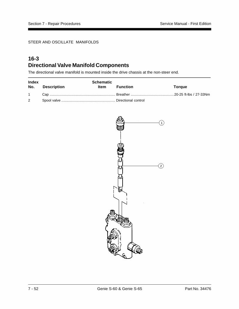
7 - 52 Genie S-60 & Genie S-65 Part No. 34476
Service Manual - First EditionSection 7 - Repair Procedures
16-3Directional Valve Manifold ComponentsThe directional valve manifold is mounted inside the drive chassis at the non-steer end.
Index SchematicNo. Description Item Function Torque
1 Cap ................................................................... Breather ............................................20-25 ft-lbs / 27-33Nm
2 Spool valve ....................................................... Directional control
STEER AND OSCILLATE MANIFOLDS
1
2
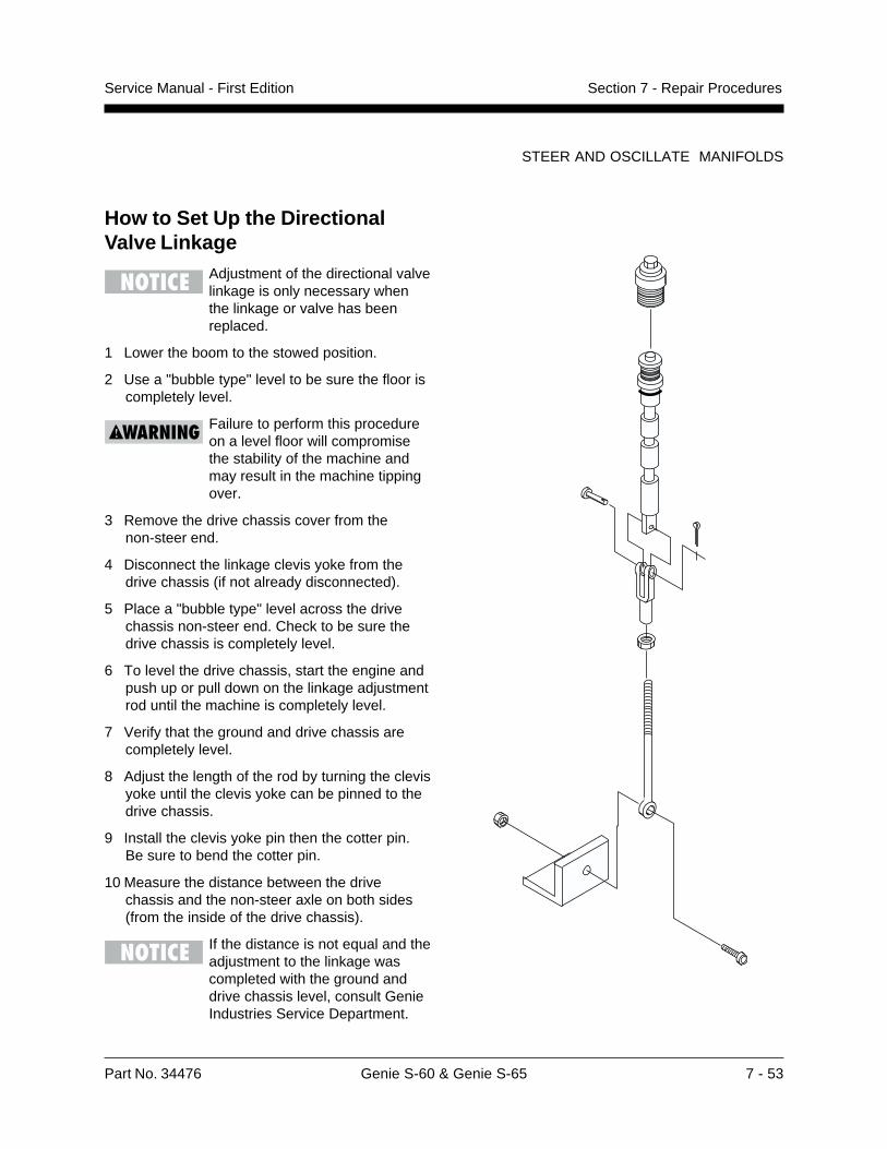
Part No. 34476 Genie S-60 & Genie S-65 7 - 53
Service Manual - First Edition Section 7 - Repair Procedures
STEER AND OSCILLATE MANIFOLDS
How to Set Up the DirectionalValve Linkage
Adjustment of the directional valvelinkage is only necessary whenthe linkage or valve has beenreplaced.
1 Lower the boom to the stowed position.
2 Use a "bubble type" level to be sure the floor iscompletely level.
Failure to perform this procedureon a level floor will compromisethe stability of the machine andmay result in the machine tippingover.
3 Remove the drive chassis cover from thenon-steer end.
4 Disconnect the linkage clevis yoke from thedrive chassis (if not already disconnected).
5 Place a "bubble type" level across the drivechassis non-steer end. Check to be sure thedrive chassis is completely level.
6 To level the drive chassis, start the engine andpush up or pull down on the linkage adjustmentrod until the machine is completely level.
7 Verify that the ground and drive chassis arecompletely level.
8 Adjust the length of the rod by turning the clevisyoke until the clevis yoke can be pinned to thedrive chassis.
9 Install the clevis yoke pin then the cotter pin.Be sure to bend the cotter pin.
10 Measure the distance between the drivechassis and the non-steer axle on both sides(from the inside of the drive chassis).
If the distance is not equal and theadjustment to the linkage wascompleted with the ground anddrive chassis level, consult GenieIndustries Service Department.

7 - 54 Genie S-60 & Genie S-65 Part No. 34476
Service Manual - First EditionSection 7 - Repair Procedures
STEER AND OSCILLATE MANIFOLDS
16-4Steer Manifold ComponentsThe steer manifold is mounted to the engine side tray.
Index SchematicNo. Description Item Function Torque
1 3 position 4 way D03 valve .............................. Steering .............................................30-35 in-lbs / 3-4 Nm
2 Priority flow regulator valve, 3 gpm (13.2 l/min)A ........... Oscillate ............................................10-12 ft-lbs / 14-16 Nm
Plug Torque Specifications
Description Hex size Torque
SAE No. 2 1/8 50 in-lbs / 6 Nm
SAE No. 4 3/16 13 ft-lbs / 18 Nm
SAE No. 6 1/4 18 ft-lbs / 24 Nm
Description Hex size Torque
SAE No. 8 5/16 50 ft-lbs / 68 Nm
SAE No. 10 9/16 55 ft-lbs / 75 Nm
SAE No. 12 5/8 75 ft-lbs / 102 Nm
1
2
Part No. 34476 Genie S-60 & Genie S-65 7 - 55
Service Manual - First Edition Section 7 - Repair Procedures
17-2Torque Hub
How to Remove a DriveTorque Hub1 Remove the drive motor. See 17-1, How to
Remove a Drive Motor.
2 Disconnect the hydraulic hose from the brakeand plug it. Then remove the hydraulic fittingand the bleed valve.
3 Loosen the wheel lug nuts. Do notremove them.
4 Center a lifting jack under the non-steeringaxle. Raise the machine and place blocksunder the drive chassis to support it.
5 Remove the wheel lug nuts, then the tire andwheel assembly.
6 Place a second lifting jack under the torque hubfor support.
7 Remove the bolts that attach the torque hub tothe chassis, then remove the torque hub.
Crushing hazard. The torquehub will fall if it is not properlysupported when the mountingbolts are removed.
Torque specifications
Lug nut (dry) 420 ft-lbs569.5 Nm
Lug nut (lubricated) 320 ft-lbs433.9 Nm
Drive torque hub mounting bolts 120 ft-lbs163 Nm
Drive motor mounting bolts 75 ft-lbs102 Nm
17-1Drive Motor
Component damage hazard.Repairs to the motor should onlybe performed by an authorizedSundstrand-Sauer dealer.
How to Remove a Drive MotorA drive motor can only be removed from the insideof the chassis.
Component damage hazard. Thework area and surfaces where thisprocedure will be performed mustbe clean and free of debris thatcould get into the hydraulicsystem and cause severecomponent damage. Dealerservice is recommended.
1 Disconnect the hydraulic hoses from the drivemotor and plug them.
Bodily injury hazard. Sprayinghydraulic oil can penetrate andburn skin. Loosen hydraulicconnections very slowly to allowthe oil pressure to dissipategradually. Do not allow oil to squirtor spray.
2 Remove the drive motor mounting bolts.
3 Slide the drive motor shaft out of the brake andthen remove it.
Torque specifications
Drive motor mounting bolts 75 ft-lbs 102 Nm
Non-steering Axle Components
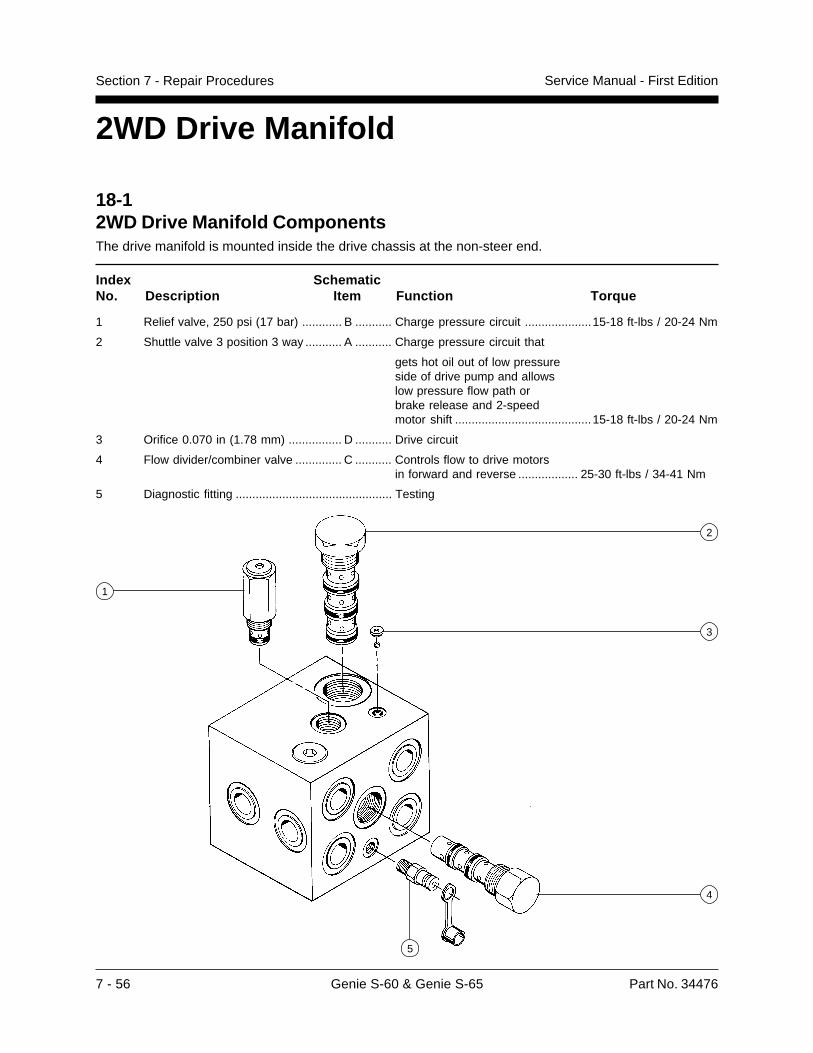
7 - 56 Genie S-60 & Genie S-65 Part No. 34476
Service Manual - First EditionSection 7 - Repair Procedures
2WD Drive Manifold
18-12WD Drive Manifold ComponentsThe drive manifold is mounted inside the drive chassis at the non-steer end.
Index SchematicNo. Description Item Function Torque
1 Relief valve, 250 psi (17 bar) ............ B ........... Charge pressure circuit ....................15-18 ft-lbs / 20-24 Nm
2 Shuttle valve 3 position 3 way ........... A ........... Charge pressure circuit that
gets hot oil out of low pressureside of drive pump and allowslow pressure flow path orbrake release and 2-speedmotor shift .........................................15-18 ft-lbs / 20-24 Nm
3 Orifice 0.070 in (1.78 mm) ................ D ........... Drive circuit
4 Flow divider/combiner valve .............. C ........... Controls flow to drive motorsin forward and reverse .................. 25-30 ft-lbs / 34-41 Nm
5 Diagnostic fitting ............................................... Testing
2
4
1
3
5
Part No. 34476 Genie S-60 & Genie S-65 7 - 57
Service Manual - First Edition Section 7 - Repair Procedures
2WD DRIVE MANIFOLD
Plug Torque Specifications
Description Hex size Torque
SAE No. 2 1/8 50 in-lbs / 6 Nm
SAE No. 4 3/16 13 ft-lbs / 18 Nm
SAE No. 6 1/4 18 ft-lbs / 24 Nm
SAE No. 8 5/16 50 ft-lbs / 68 Nm
SAE No. 10 9/16 55 ft-lbs / 75 Nm
SAE No. 12 5/8 75 ft-lbs / 102 Nm
18-2Valve Adjustments
How to Adjust the ChargePressure Relief Valve1 Connect a 0 to 600 psi (0 to 41 bar) pressure
gauge to the test port located on the drivemanifold.
Bodily injury hazard. Sprayinghydraulic oil can penetrate andburn skin. Loosen hydraulicconnections very slowly to allowthe oil pressure to dissipategradually. Do not allow oil tosquirt or spray.
2 Start the engine from the platform controls.
3 Drive the machine slowly in either direction andobserve the pressure reading on the pressuregauge.
4 Turn the engine off. Hold the relief valve andremove the cap (index 1).
5 Adjust the internal hex socket. Turn it clockwiseto increase the pressure or counterclockwiseto decrease the pressure. Then install thevalve cap.
6 Restart the engine. Drive the machine in eitherdirection and recheck the valve pressure.
7 Turn the engine off, then remove thepressure gauge.
Relief valve specifications
Pressure 250 psi17 bar
7 - 58 Genie S-60 & Genie S-65 Part No. 34476
Service Manual - First EditionSection 7 - Repair Procedures
19-14WD Drive Manifold ComponentsThe drive manifold is mounted inside the drive chassis at the non-steer end.
Index SchematicNo. Description Item Function Torque
1 Shuttle valve 3 position 3 way ........... A ........... Charge pressure circuitthat gets hot oil out of low pressureside of drive pump and allows lowpressure flow path or brakerelease and 2-speed motor shift ...... 15-18 ft-lbs / 20-24 Nm
2 Relief valve, 250 psi (17 bar) ............ E ........... Charge pressure circuit ................... 15-18 ft-lbs / 20-24 Nm
3 Orifice 0.052 in (1.32 mm) ................ H ........... Drive circuit, non-steer end
4 Flow divider/combiner valve .............. C ........... Controls flow to steer enddrive motors in forwardand reverse ...................................... 25-30 ft-lbs / 34-41 Nm
5 Flow divider/combiner valve .............. A ........... Controls flow to non-steer enddrive motors in forwardand reverse ...................................... 25-30 ft-lbs / 34-41 Nm
6 Orifice 0.070 in (1.78 mm) ................ F ........... Drive circuit, steer end
7 Orifice 0.070 in (1.78 mm) ................ G ........... Drive circuit, non-steer end
8 Flow divider/combiner valve .............. B ........... Controls flow to flowdivider/combiner valves 4 and 5 ...... 25-30 ft-lbs / 34-41 Nm
9 Diagnostic fitting ............................................... Testing
4WD Drive Manifold
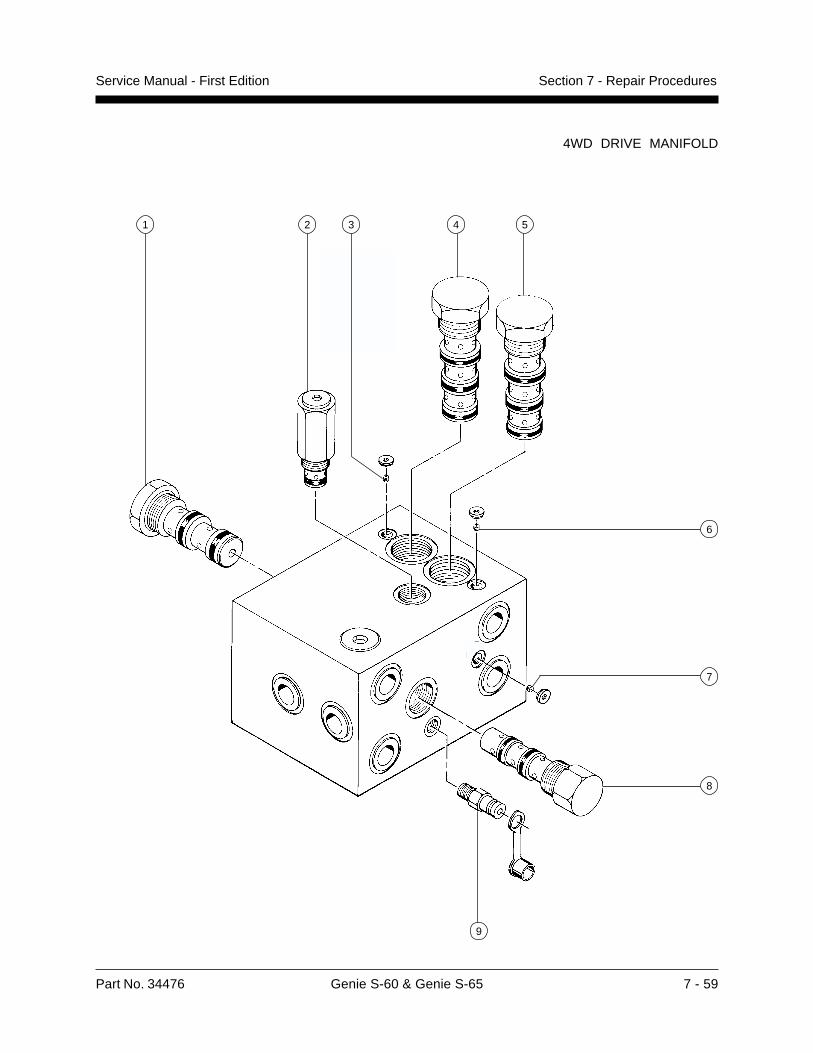
Part No. 34476 Genie S-60 & Genie S-65 7 - 59
Service Manual - First Edition Section 7 - Repair Procedures
4WD DRIVE MANIFOLD
1 2 4 5
8
3
6
7
9
7 - 60 Genie S-60 & Genie S-65 Part No. 34476
Service Manual - First EditionSection 7 - Repair Procedures
4WD DRIVE MANIFOLD
Plug Torque Specifications
Description Hex size Torque
SAE No. 2 1/8 50 in-lbs / 6 Nm
SAE No. 4 3/16 13 ft-lbs / 18 Nm
SAE No. 6 1/4 18 ft-lbs / 24 Nm
SAE No. 8 5/16 50 ft-lbs / 68 Nm
SAE No. 10 9/16 55 ft-lbs / 75 Nm
SAE No. 12 5/8 75 ft-lbs / 102 Nm
19-2Valve Adjustments
How to Adjust the ChargePressure Relief Valve1 Connect a 0 to 600 psi (0 to 41 bar) pressure
gauge to the test port located on the drivemanifold.
Bodily injury hazard. Sprayinghydraulic oil can penetrate andburn skin. Loosen hydraulicconnections very slowly to allowthe oil pressure to dissipategradually. Do not allow oil tosquirt or spray.
2 Start the engine from the platform controls.
3 Drive the machine slowly in either directionand observe the pressure reading on thepressure gauge.
4 Turn the engine off. Hold the relief valve andremove the cap (index 2).
5 Adjust the internal hex socket. Turn it clockwiseto increase the pressure or counterclockwiseto decrease the pressure. Then install thevalve cap.
6 Restart the engine. Drive the machine in eitherdirection and recheck the valve pressure.
7 Turn the engine off, then remove thepressure gauge.
Relief valve specifications
Pressure 250 psi17 bar

Part No. 34476 Genie S-60 & Genie S-65 7 - 61
Service Manual - First Edition Section 7 - Repair Procedures

Genie North America18340 NE 76th Street
P.O. Box 97030
Redmond, Washington
98073-9730
Genie EuropeBrunel Drive
Newark
Nottinghamshire
NG24 2EG England
Distributed By: