hopper design cliff notes
TRANSCRIPT

1
Hopper Design Cliff Notes
Greg Mehos, Ph.D., P.E. [email protected] [email protected]
978-799-7311
Flow patterns
There are two general flow patterns that can occur when a bulk solid is discharged from a hopper: funnel flow and mass flow. In funnel flow, an active flow channel forms above the outlet, with stagnant material remaining at the periphery. In mass flow, the entire solids bed is in motion when the material is discharged from the outlet. Funnel flow occurs when the walls of the hopper are not steep enough or have low enough friction to allow flow along them. Mass flow hoppers typically have steep and/or low-friction walls. Flow patterns are illustrated in Figure 1.
Figure 1. Flow patterns; left: funnel flow; right: mass flow.
The choice between a funnel flow hopper and mass flow hopper depends on a number of factors. If a material has segregation tendencies, mass flow should be selected. Materials that are likely to cake or readily form stable ratholes should be handled in mass flow hoppers. Mass flow is also recommended when fine powders are handled, as they are more likely to flood feeders, and when applications require a steady solids discharge rate.
Funnel flow is fine as long as segregation is not a concern, the powder does not aerate, and the hopper outlet is large enough to prevent a stable rathole from forming. In many cases, the size of a hopper outlet required to prevent a stable rathole from developing is considerably larger than that required to avoid a cohesive arch from forming. In general, mass flow hoppers are preferred over funnel flow hoppers.

2
Flow properties
To design a hopper for reliable flow, the following bulk solids flow properties must be known: (1) cohesive strength, (2) internal friction, (3) compressibility, (4) wall friction, and (5) permeability. These properties are measured using shear cell, wall friction, and permeability testers. The relationship between a bulk material’s unconfined yield strength and major consolidation stress is called the flow function. The effective yield locus provides the relationship between the major consolidation stress and the effective angle of friction. Compressibility is the relationship between a material’s bulk density and major consolidation stress. Permeability relates the pressure drop through a bed of material and the superficial gas velocity. Details of the test equipment and testing procedures can be found in the 9th edition of Perry’s Chemical Engineers’ Handbook.
Mass flow hoppers
Two critical design parameters are specified for mass flow hoppers: the hopper angle and the size of the outlet. The hopper angle required to allow mass flow depends on the effective angle of friction δ, the wall friction angle, and the geometry of the hopper. Figures 2 and 3 provide recommended mass flow hopper angles for conical hoppers and hoppers with flat walls and slotted outlets based on analyses developed by Jenike [1,2]. Values of the allowable hopper angle θ’ are on the horizontal axis, and values of the angle of wall friction ϕ’ are on the vertical axis. The boundaries between mass flow and funnel flow depend on the effective angle of friction δ. Any combination of θ’ and ϕ’ that falls within the limiting mass flow region of the chart will provide mass flow.
Figure 2. Theoretical mass flow hopper angles for hoppers with round or square outlets. Note: a minimum safety factor of 2 to 3° should be used.

3
Figure 3. Recommended mass flow hopper angles for wedge-shaped hoppers.
A 2-3° safety factor with respect to the theoretical mass flow hopper angle is recommended in the design of a conical mass flow hopper. On the other hand, angles of hoppers with flat walls and slotted outlets (e.g., wedge-shaped and transition hoppers) in which flow is planar can be 5-10° greater than recommended in Figure 3 without risking funnel flow. The outlet of a planar flow hopper must be at least two times as long as it is wide for Figure 3 to apply if it has vertical end walls and three times as long if its end walls are converging.
Note that design rules for planar hoppers cannot be applied to pyramidal hoppers. Guidelines for conical hoppers should instead be used. Be aware that the valley angles formed at the intersections of the sloping walls of pyramidal hoppers can be significantly less steep than those of the hopper walls themselves. The valley angle from vertical θv can be calculated from
θv = tan−1 tan2θside + tan
2θend (1)
where θside and θend are the side and end wall angles from vertical, respectively. The valley, which is more shallow than the side or end walls, must be steep enough to allow mass flow.
An analytical description the theoretical boundary between the mass flow and funnel flow regions for conical hoppers is as follows [2]:
ʹθ = 90°− 12cos−1 1− sinδ
2sinδ
⎛
⎝⎜
⎞
⎠⎟−β (2)

4
where β is calculated from
2β = ʹφ + sin−1 sin ʹφsinδ
⎛
⎝⎜
⎞
⎠⎟ (3)
Note that a safety factor of 2-3° should be used with Equation 2. For hoppers with slotted outlets, the following equation can be used to calculate the mass flow boundary [5]:
ʹθ =exp[3.75(1.01)(δ−30°)/10 ]− ʹφ
0.725(tanδ)1/5 (4)
for ϕ’ less than δ - 3°.
These equations may be serpentine, but they can be readily input into spreadsheets and other software. The figures can be used to confirm the calculations.
The stress at the wall and the major consolidation stress are not equal. The wall friction angle is determined by superimposing the wall yield locus and effective yield locus on the same graph as shown in Figure 4. The value of ϕ’ is found from the intersection of the Mohr’s circle that passes through σ1 and the wall yield locus.
Figure 4. Construction of effective yield locus and wall yield locus.
If the wall yield locus is linear, which is often true at low stresses, it can be described by
ʹτ = a ʹσ +b (5)
where τ’ and σ’ are the shear and normal stresses at the wall surface, respectively and a and b are empirical constants determined from regression. The normal stress can then be calculated from
ʹσ =−β + β 2 − 4αγ
2α (6)
EYL
WYL
σ1σ’
δφ�
NormalStressσ
ShearS
tressτ

5
where
α = a2 +1 (7)
β = 2(ab−σ avg ) (8)
and
γ = b2 +σ avg2 − R2
(9)
The wall friction angle is then calculated from
ʹφ = tan−1 ʹτʹσ
⎛
⎝⎜
⎞
⎠⎟ (10)
where the shear stress at the wall τ’ is calculated from Equation 5.
To prevent the formation of a stable cohesive arch at the outlet of a hopper, the external stress must be greater than the powder’s unconfined yield strength. Jenike [1,2] defined the flow factor ff as the ratio of the major consolidation stress σ1 to the stress on the abutment of the arch that naturally forms at the outlet σ :
ff = σ1σ (11)
The flow factor depends on the powder’s effective angle of friction δ, the wall friction angle ϕ’, and the hopper angle θ’. Charts that provide flow factors are provided by Jenike [1] and the 9th edition of Perry’s Chemical Engineers’ Handbook. Examples are given in Figures 5-8.
Analytical expressions of the flow factor are provide by Arnold and McLean [3,4]:
ff = Y (1+ sinδ)H (α)2(X −1)(sinα)
(12)
where
X =2i sinδ1− sinδ
sin(2β +α)sinα
+1⎡
⎣⎢
⎤
⎦⎥ (13)
Y = [2(1− cos(β +α))]i sinα(β +α)1−i + sinβ sin1+i (β +α)
(1− sinδ)sin2+i (β +α) (14)
and

6
H ( ʹθ ) = 130°+ ʹθ65
⎛
⎝⎜
⎞
⎠⎟
i200°+ ʹθ200°
⎛
⎝⎜
⎞
⎠⎟
1−i
(15)
The value of i in Equations 13-15 is equal to 1 for circular outlets and 0 for slotted outlets.
Flow factors typically range between 1.2 and 1.6 but can be much greater if wall friction is exceptionally low and hopper walls are very steep.
Figure 5. Flow factors for conical hoppers, δ = 40°.
Figure 6. Flow factors for conical hoppers, δ = 50°.
HopperAnglefromVer.calθ�
Hopp
erAnglefrom
Ver.calϕ�
AngleofW
allFric/o
nφ’
1.2
1.3
HopperAnglefromVer.calθ�
Hopp
erAnglefrom
Ver.calϕ�
AngleofW
allFric/o
nφ’

7
Figure 7. Flow factors for planar flow hoppers with slotted outlets, δ = 40°.
Figure 8. Flow factors for planar flow hoppers with slotted outlets, δ = 50°.
The size of the outlet required to prevent a cohesive arch from developing in a mass flow hopper can be determined by first superimposing the flow factor and flow function on the same graph. The flow factor is constructed by drawing a line having a slope equal to 1/ff through the origin. As shown in Figure 9, three possibilities exist:
1. The flow function lies below the flow factor, and the two do not intersect. When this is the case, the stress imparted on the abutments of the arch is always greater than the material’s cohesive strength, and therefore no minimum outlet dimension
HopperAnglefromVer.calθ�
Hopp
erAnglefrom
Ver.calϕ�
AngleofW
allFric/o
nφ’
HopperAnglefromVer.calθ�
Hopp
erAnglefrom
Ver.calϕ�
AngleofW
allFric/o
nφ’

8
requirement to prevent cohesive arching exists. Instead, the outlet dimension B is determined by other considerations such as the required discharge rate. The hopper angle required for mass flow requires the major consolidation stress σ1 at the outlet to be known. This stress is calculated from
σ1 = ffρbgBH ( ʹθ )
(16)
2. The flow function lies above the flow factor and the curves do not intersect. The powder will not flow due to gravity alone. Consideration should be given to changing the flow properties of the material, such as increasing its particle size or using a flow aid, or using a standpipe.
3. The flow function and flow factor intersect. At the intersection of the two lines, the arch stress and the cohesive strength of the bulk solid are the identical and equal to the critical stress σcrit. The hopper outlet diameter that must be exceeded to prevent arching, Bmin, can be calculated from
Bmin =H ( ʹθ )σ crit
ρbg (17)
A safety factor of 1.2 is sometimes multiplied to the value of Bmin. Because the bulk density ρb, the effective angle of friction δ, and the angle of wall friction ϕ’ each depend on stress, calculating critical hopper angles and arching dimensions is an iterative procedure. Figure 10 is a flowchart for calculating the minimum hopper outlet diameter and recommended mass flow hopper angle when the flow function and flow factor intersect. A flowchart for determining the recommended mass flow hopper angle for selected outlet diameters is given in Figure 11.
Figure 9. Plot showing both flow factor and Flow Function.
Uncon
fined
YieldStren
gthf C

9
Figure 10. Flowchart for determining critical hopper outlet size and mass flow hopper angle.
Guessff
Determineσ1fromintersec/onofflowfactor
andflowfunc/on
Calculateδ
Selectθ’thatallowsmassflow(include3°safety
factorifconical)
ffconverged?
Calculatenewffusingupdatedvaluesofδ,φ’,
and θ’
Calculateφ’
Calculateσcri(ρb,H(θ’)
CalculateBmin
Yes
No
CalculateH(θ’)’

10
Figure 11. Flowchart for determining recommended mass flow hopper angle for a specified outlet diameter.
ChooseB
Guessσ1
Selectθ’thatallowsmassflow(include3°safetyfactor)
σ1converged?
Calculateff
CalculateH(θ’)
Updateδ,ϕ’
Yes
No
Solveσ1=ffρbgBH(θ’)
θ’ is recommended value
Determineδ,ϕ’

11
To prevent mechanical interlocking at the hopper outlet, the following rules of thumb are used: for a conical hopper, the outlet diameter should be at least 6-8 times the size of the largest particle that will be handled; for hoppers with slotted outlets, the outlet width should be at least 3-4 times the largest particle size.
Unless the bulk material is expected to be handled continuously, time cohesive strength and wall friction test results should be used for hopper design.
The outlet must also be large enough to provide the desired discharge rate. For coarse powders, the solids discharge velocity vo is given by
vo =Bg
2(i +1) tan( ʹθ ) (18)
from which the mass discharge rate can be calculated from from
!ms = ρboAovo (19)
where Ao is the cross-sectional area of the outlet, and ρbo is the bulk density at the outlet.
The maximum discharge rate of a fine powder can be orders of magnitude less than that of a coarse powder due to an adverse gas pressure gradient that develops near the outlet as the powder dilates. For fine powders handled in a hopper that has an outlet significantly greater than fC/(ρbg),
vo =Bg
2(m+1) tan ʹθ1+ 1
ρbgdPdz O
⎛
⎝⎜⎜
⎞
⎠⎟⎟ (20)
with
dPdz o
=voρbogKo
1ρbmp
−1ρbo
⎛
⎝⎜⎜
⎞
⎠⎟⎟ (21)
where ρbmp is the bulk density at the location inside the hopper where the gas pressure is at a minimum and Ko is a permeability parameter with units of velocity. Frequently, Darcy’s Law is expressed as
u = −CηdPdz
(22)
where u is the superficial fluid velocity, C is the Darcy permeability, and η is the viscosity of the fluid. K and C are related by
K =C ρbgη
(23)

12
Note that when K is equal to ρbg, the forces on a particle due to the pressure gradient and gravity are equal and opposite. Therefore, K is approximately equal to the bulk material’s minimum fluidization velocity.
Equations 30 and 31 can be combined to give the following quadratic equation:
2(i +1) tan ʹθBg
⎡
⎣⎢
⎤
⎦⎥vo
2 +1Ko
1−ρboρbmp
⎛
⎝⎜⎜
⎞
⎠⎟⎟
⎡
⎣⎢⎢
⎤
⎦⎥⎥vo −1= 0 (24)
For design purposes, which will provide a conservative result, ρbo can be set equal to the material’s minimum bulk density and ρbmp is set equal to the bulk density at the major consolidation stress at the hopper cylinder junction, which is calculated from the Janssen equation [6]:
(25)
where RH is the hydraulic radius of the vertical section of the hopper, h is its height, and k is the Janssen coefficient. Average values of the bulk density and wall friction angle are used in Equation 25. The Janssen parameter can be assumed equal to 0.4.
Alternatively, the differential version of the Janssen equation can be used. The differential equation can be numerically integrated if the bulk density’s relation to the major consolidation stress (vertical stress) is known. The differential form is given by:
dσ v
dz+k tan ʹφRH
σ v = ρbg (26)
Funnel flow hoppers
Funnel flow hoppers allow significantly more capacity in installations where headrooom is limited. The outlet of a funnel flow hopper must be large enough to prevent both a cohesive arch and stable rathole from developing.
The critical rathole diameter DF, i.e., the diameter of a round outlet or diagonal of a slotted outlet that must exceeded to ensure that a rathole will collapse, is calculated from
DF =G(φt ) fCρbg
(27)
where ϕt is the static angle of internal friction, which is determined from time cohesive strength tests, and fC is the unconfined yield strength of the bulk solid at the consolidation pressure given by the Janssen equation (Equation 25 or 26). The function G(ϕt) is a function given by Jenike [1], which is plotted in Figure 12.
An analytical approximation to G(ϕt) is given by
σ1 =ρbgRHk tan ʹφ
1− exp −k(tan ʹφ )hRH
⎛
⎝⎜⎜
⎞
⎠⎟⎟
⎡
⎣⎢⎢
⎤
⎦⎥⎥

13
G(φt ) = −5.066+0.490φt −0.0112φt2 +0.000108φt
3 (28)
Figure 12. Function G(ϕt)
If a hopper with a square or round outlet is designed with an opening larger than Df, cohesive arching will not occur. The width of the slotted outlet of a funnel flow hopper with flat walls must be large enough to prevent a cohesive arch from developing. The same procedure that is used to determine the minimum outlet width to prevent arching in a planar flow mass flow hopper is followed, except that a flow factor of 1.7 is used.
For some bulk materials, designing a hopper for expanded flow is an option. An expanded flow hopper is essentially a funnel flow hopper above a mass flow hopper. The upper diameter of the mass flow section must be larger than the critical rathole diameter DF, while its outlet size must be larger than the critical arching dimension Bmin. As the bulk material is discharged, it will be in motion in the bottom portion of the vessel, but flow will only occur in a flow channel in the top portion of the vessel centered over the outlet. Any rathole will collapse, and the hopper will completely empty.
Capacities
A reasonable height-to-diameter ratio (H/D) of the cylinder section should be used, with ratios between about 1.5 to 4 usually being the most economical. The volume V and height H of some common hopper designs are given in Figure 13.
2
4
6
8
10
12
30 40 50 60 70
G( φt)
Static Angle of Internal Friction φt (°)Sta$cAngleofInternalFric$onϕt
G(ϕ
t)

14
Conical
Pyramidal
Transition
H =D− B2 tanαside
=D− L2 tanα end
Figure 13. Hopper capacities.
a
B
D
α
D
D
α
B
H =D− B2 tanα
V =π (D3 − B3)24 tanα
a
A
asidea end
B
b
Valley
αα
�� ���
B
b a
A
H =A− a
2 tanαside=
B−b2 tanαend
V =H[2(AB+ ab)+ Ab+ aB]
6
B
D
aside
L
a endα αα��� α����
B L
D
V ≈πD2
12+BL3+D(B+ 2L)12
⎡
⎣⎢
⎤
⎦⎥H

15
Feeders
Feeders can be a source of hopper flow problems if improper equipment are used or if they are improperly designed. This is especially true for hoppers with slotted outlets, where feeders should be designed to draw uniformly from the entire cross-section of the outlet in order for mass flow to occur. However, even hoppers with round outlets can have uneven flow if a proper interface is not utilized.
There are two primary categories of feeders available to handle bulk solids: volumetric and gravimetric. A volumetric feeder discharges a particular volume of powder over a period of time. This type of feeder is adequate for many applications, especially for mass flow hoppers, in which the bulk density of the powder at the hopper outlet is nearly independent of level inside the vessel.
A gravimetric feeder relies on a control system that adjusts the speed of the feeder based on loss in weight measurements. Because the controller cannot determine a discharge rate when its hopper is being filled with material, typically two hoppers are used in series. The upstream system is designed so that it can feed the downstream vessel very quickly. During the fill cycle, the downstream feeder is operated in a volumetric mode (i.e., at a constant speed), and then in gravimetric mode (i.e., its speed is controlled by measuring the loss in weight of material inside the hopper) once the downstream hopper is filled. Gravimetric feeders are usually much more expensive than volumetric feeders.
An advantage of mass flow hoppers as that the bulk density at the hopper outlet is independent of the height of material inside the vessel. If precise measurement of the discharge rate from a hopper is not critical, volumetric feeders are often adequate and a less expensive alternative to gravimetric feeders.
Rotary valves
Rotary valves are often used beneath hoppers with round or square outlets. They are particularly useful for applications where a seal must be provided to prevent air from flowing out of or into the hopper outlet. A schematic of a rotary valve is shown in Figure 14.
If a rotary valve is used, a short vertical spool section should be installed between the hopper outlet and valve inlet. Otherwise, material may flow preferentially from the upside of the valve and affect the flow pattern inside the vessel as shown in Figure 15.

16
Figure 14. Rotary valve feeder.
Figure 15. Flow of powder through rotary valve with (left) and without (right) spool section.
When the powder is dropped from a pocket, the air or gas that replaces it can be pumped back into the hopper. A vent line should be considered, especially if the rotary valve discharges material into a high-pressure line. Typically, the vent line directs air either into a dust collector or into the top of the hopper.
The capacity of a rotary valve can be calculated from
(29)
where q is the volumetric discharge rate, N is the rotary valve speed, D and d are the vane and shaft diameters, respectively, and W is the width of the vane. Rotary valve speeds of 15 - 45 rpm are preferable.
q = Nπ (D2 − d 2 )W4

17
Screw feeders
Screw feeders are primarily used to control the discharge of powders from hoppers with slotted outlets. A screw is comprised of a series of flights wound around one or more shafts.
A screw that has constant pitch and constant shaft diameter will give rise to the formation of a flow channel at the back of the hopper over the first flight of the screw. As illustrated in Figure 16, this channel will draw material from the top surface into the flow channel until a stable rathole forms and the channel empties. The rathole will then periodically fail as the base of the material fails above the screw. This will continue to broaden the flow channel, and this cyclic fail-flow-empty cycle will continue until the hopper empties.
Figure 16. Screw feeder with constant pitch, constant diameter screw.
A mass flow screw feeder, comprised of a tapered section followed by an increasing pitch section, ensures that the capacity of the feeder increases in the direction of flow (see Figure 17). The length of the cone and the pitch schedule are chosen such that the capacity of the screw increases linearly along the hopper length. The screw diameter should equal the width of the hopper outlet, and the trough should be about one inch wider than the screw. Fabrication tolerances limit the length-to-width ratio of the hopper to less than 8, preferably less than 6.
Figure 17. Mass flow screw feeder.
18
The final pitch determines the capacity of the screw feeder, that is,
(30)
where D and d are the screw and shaft diameters, respectively, q is the volumetric discharge rate, Pf is the pitch of the final screw (also known as the conveying pitch), t is the flight thickness, and N is the screw speed. Screw feeders are generally run at about 80 percent of full capacity and are best operated between 3 and 40 rpm.
The trough should be U-shaped, rather than V-shaped to prevent material from stagnating. Screw flights should have lower friction than the trough; otherwise, material will only be spun about the shaft and will not be conveyed.
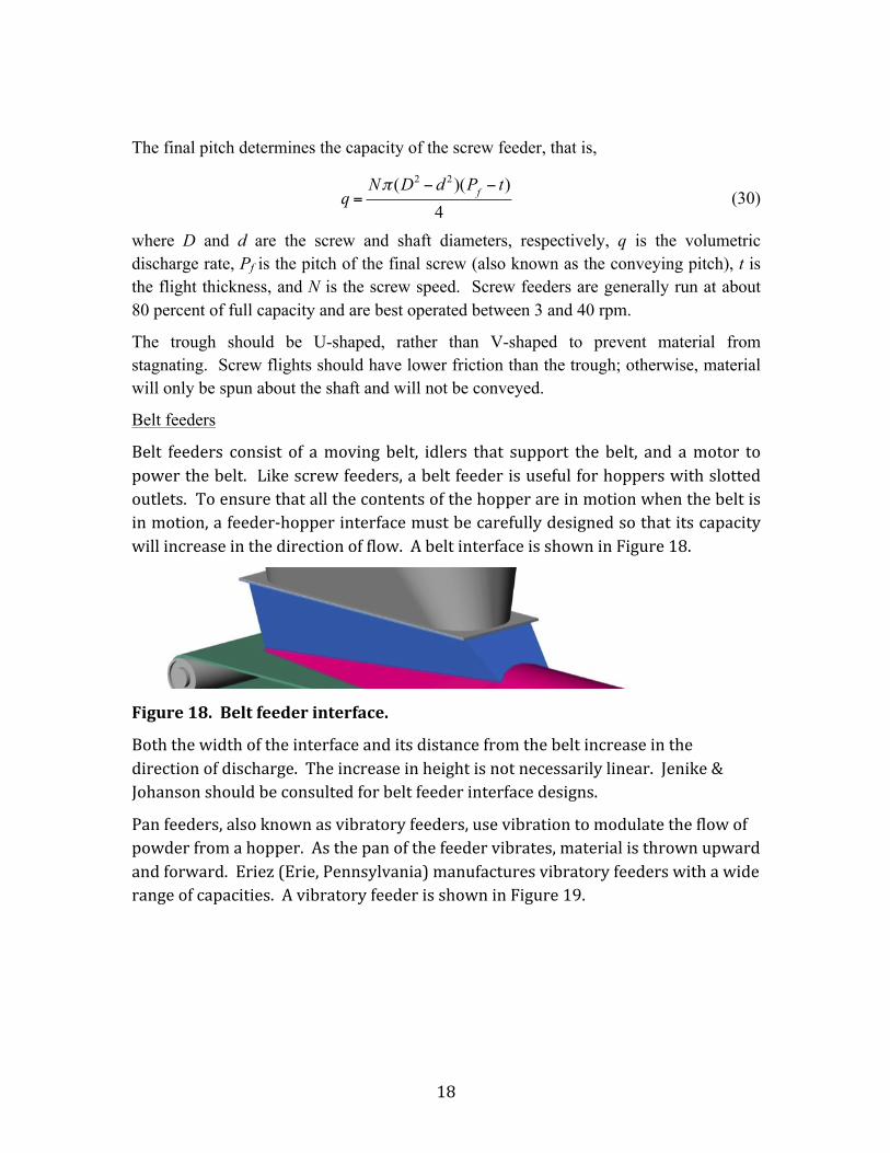
Belt feeders
Belt feeders consist of amoving belt, idlers that support the belt, and amotor topowerthebelt. Likescrewfeeders,abeltfeederisusefulforhopperswithslottedoutlets.Toensurethatallthecontentsofthehopperareinmotionwhenthebeltisinmotion,afeeder-hopperinterfacemustbecarefullydesignedsothatitscapacitywillincreaseinthedirectionofflow.AbeltinterfaceisshowninFigure18.
Figure18.Beltfeederinterface.
Boththewidthoftheinterfaceanditsdistancefromthebeltincreaseinthedirectionofdischarge.Theincreaseinheightisnotnecessarilylinear.Jenike&Johansonshouldbeconsultedforbeltfeederinterfacedesigns.
Panfeeders,alsoknownasvibratoryfeeders,usevibrationtomodulatetheflowofpowderfromahopper.Asthepanofthefeedervibrates,materialisthrownupwardandforward.Eriez(Erie,Pennsylvania)manufacturesvibratoryfeederswithawiderangeofcapacities.AvibratoryfeederisshowninFigure19.
q =Nπ (D2 − d 2 )(Pf − t)
4

19
Figure19.Eriezvibratoryfeeder.
Silettafeedersuseanarrayoflouversandavibratorydrivetocontrolthedischargerateofabulkmaterialfromahopper.Theangleandspacingofthelouversaresetsuchthatthematerialwillfinditsangleofreposeandwillnotdischargeunlessthefeederisvibrating.Figure20isaphotographofasilettafeeder.
Figure20.Silettalouveredfeeder.
Belt,vibratingpan,andsilettafeedersshouldnotbeusedwithcautioniffinepowdersaredischarged.Finepowdersmayfluidizeandfloodthefeederifoperatedattoohigharateorifratholesinafunnelflowhoppercollapseandthepowderremainsaerated,resultinginuncontrollabledischargeofthematerial.

20
References
1. Jenike, A.W., Storage and Flow of Solids, Bulletin 123, University of Utah Engineering Station, 1964 (revised, 1976).
2. Jenike, A.W., Gravity Flow of Solids, Bulletin 108, University of Utah Engineering Station, 1961.
3. Arnold, P.C. and A.G. McLean, “An Analytical Solution for the Stress Function at the Wall of a Converging Channel”, Powder Techn., 13, 255 (1976).
4. Arnold, P.C. and A.G. McLean, “Improved Analytical Flow Factors for Mass-Flow Hoppers”, Powder Techn., 15, 276 (1976).
5. Arnold, P.C. and A.G. McLean, Bulk Solids: Storage, Flow and Handling, TUNDRA Publications, 1980.
6. Janssen, H.A., “Getreidedruck in Silozellen”, Z. Ver. Dt. Ing., 39, 1045 (1895).