horizontal metal pump
TRANSCRIPT
RN, RNSi Horizontal metal pump

2
The RN
Standard chemical pump The standardised chemical pumps RN and RNSi (ferro- silicon cast iron) are used for pumping all kinds of liquids in the wide field of chemical processing, basic chemicals and environmental technology.
Design features
� Design: horizontal, single-stage � Construction: back pull out design according to ISO 2858
� Casing design: single or double volute casing � Bearing lubrication: grease or oil lubrication � Installation versions: Base frame welded or base plate cast
� Ambient temperature: -20 °C to +60 °C � Solid content limit value: approx. 5 % (more with the open impeller)
RN, RNSi
Avoid unplanned downtime
The pump is equipped with the i-ALERT®2 sensor as standard. This monitors vibrations and temperature. If preset limit
values are exceeded, LEDs in the sensor light up. All measured values can be retrieved via an app or the Ai Platform. This means that necessary
measures can be taken in good time before the pump fails.

3
Options
� Inducer � Drain of volute casing � Flushing in different versions � Temperature and vibration monitoring � Flange processing in line with international standards � Centre line mounting for hot media � Mechanical seal supply systems � Pump accessories
Applications
Due to the large selection of materials, almost universal application in trade, chemistry and industry � Ammonium sulphate � Chemical industry � Chloralkali electrolysis � Caustic soda (caustic, hot) � Nitrogen fertilizer � NPK/fertiliser production � Pigments (TiO2) � Sulphuric acid
RN RNSi
Size DN 25 to 400 32 bis 250
Qmax m3/h (gpm) 2700 (11888) 1500
Hmax m (ft) 150 (492) 100
Temperature °C (°F) -40 to +300 (-40 to +572)
Standards EN 22858, ISO 2858, ISO 5199
Closed impeller Standard Standard
Open impeller Option -
Heatable Option Option
Back pull out design Standard Standard
Seal Mechanical seal, Hydrodynamic seal
Technical data

RN, RNSi4
The drawings essentially correspond to the execution. We reserve the right to make design changes.
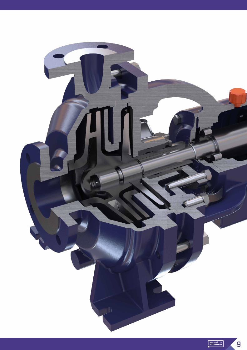
Main features
1 4
5
6
2
3
Many hydraulic sizes (also above and below ISO 2858) allow a size selection with high efficiency and low drive power.
The SIGUSS version RNSi for hot, abrasive, sulphuric acid media ensures increased safety in the plant in the armoured housing.
By using the double jacket, the whole hydrau-lic pump section can be optimally heated by steam, heat transfer oil or electric resistance heating.
The bearing bracket can be equipped with the patented i-Alert® sensor. The i-Alert® sensor enables continuous recording of pump vibrations in three dimensions, as well as the bearing temperature at the bearing bracket. The data can be read out contact-free via Bluetooth.
The wide material range of this series offers the optimum material for every application.
Robust stationary standard mechanical seal All-pac S with FKM coated single spring. The very simply constructed Allpac S has proven itself in many critical applications for decades. The installation spaces according to EN 12756 also allow the flexible use of special seals from all manufacturers. The hydrodynamic shaft seal complements the mechanical seal variants for special applica-tions where mechanical seals cannot be used economically.

5
Unarmoured design with standard mechanical seal type AllpacS (RN CS)
Armoured design with hydrodynamic shaft seal (RNSi B)
3
3
4
5

RN, RNSi6 RN, RNSi
Metal materials
High-alloy cast steel 1.4136S / RHRSCorrosion and erosion resistant high alloy ferritic cast steel. Typical applications are highly concentrated sulphuric acid up to 225 °C (437 °F), oleum, fertiliser pro-duction, crude phosphoric acid containing solids.
1.4306SHigh-quality, molybdenum-free material suitable for ap-plications such as pumping of ammonium nitrate melt, hot nitric acid at medium concentrations and also the vaporization of waste nitric acid.
1.4361Low carbon silicon alloy material for pumping strongly oxidising media. Particularly suitable for hot highly con-centrated nitric acid, e.g. 98 % HNO3.
1.4408Fully austenitic chromium nickel molybdenum steels with a good general resistance to corrosion. These materials are suitable for pumping almost all organic liquids, 50 % caustic soda up to 90 °C (194 °F), KTL paint, pure phos-phoric acid, dry chlorine, liquid sulphur, PTA and many other media.
1.4463Semi-austenitic, easily welded material with an increased strength and good general resistance to corrosion. Due to its good welding properties and wear resistance it is frequently used for jacketed pumps for handling melts containing solids, such as pitch and tar.
The range of metallic materials includes a wide range of very different types of material which are distinguished mainly by their alloy composition, their structure and their manufacturing process. This gives each material its characteristic properties and allows an optimal material to be selected to suit the application.
1.4517Duplex (Semi-austenitic), molybdenum and copper al-loyed material with a high resistance to pitting and stress corrosion. This material is one of the super duplex steels. lt can be used with crude phosphoric acid, containing solids at up to 100 °C (212 °F), hot sea water, many solu-tions containing chloride, FGD suspensions and sulphuric acid at all concentrations at low temperatures.
1.4529SA high grade special material having a high resistance to acidic media containing solids and rich in chlorides. Used in absorber and quencher fluids of the FGD, for acidic and chloride containing gypsum slurries, in the manufacture of phosphoric acid, in vaporisation and crystallisation processes and also for hot sea water.
1.4652SHigher austenitic cast material with very high corrosion resistance. Especially in very corrosive phosphoric acid with solids this material is perfectly suitable.
R 3020 Fully austenitic special stainless steel with a high molyb-denum and copper content. High resistance to pitting, stress corrosion and intercrystalline corrosion. Suitable for 70 % caustic soda up to 200 °C (392 °F), sulphuric acid at all concentrations at low and medium tempera-tures, sulphuric acid pickling solutions, in certain areas of the manufacture of phosphoric acid, for pumping solutions with a high chloride content and in spin baths.
7
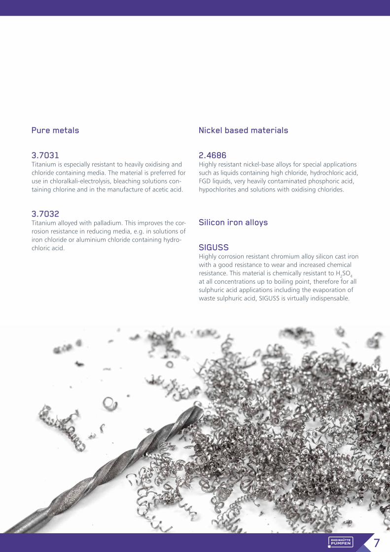
Pure metals
3.7031 Titanium is especially resistant to heavily oxidising and chloride containing media. The material is preferred for use in chloralkali-electrolysis, bleaching solutions con-taining chlorine and in the manufacture of acetic acid.
3.7032 Titanium alloyed with palladium. This improves the cor-rosion resistance in reducing media, e.g. in solutions of iron chloride or aluminium chloride containing hydro-chloric acid.
Nickel based materials
2.4686 Highly resistant nickel-base alloys for special applications such as liquids containing high chloride, hydrochloric acid, FGD liquids, very heavily contaminated phosphoric acid, hypochlorites and solutions with oxidising chlorides.
Silicon iron alloys
SIGUSS Highly corrosion resistant chromium alloy silicon cast iron with a good resistance to wear and increased chemical resistance. This material is chemically resistant to H2SO4 at all concentrations up to boiling point, therefore for all sulphuric acid applications including the evaporation of waste sulphuric acid, SIGUSS is virtually indispensable.

RN, RNSi8 RN, RNSi
SealingsDepending on the application, a selection can be made between hydrodynamic seal or mechanical seal variants.
Design CS Internal, balanced mechanical shaft seal type Allpac S by Rheinhütte with stationary spring-loaded face and rotat-ing face
Design CST Double mechanical seal with stationary seal ring and downstream standardised mechanical seal with feed thread
Design CN1 Single acting standardized mechanical seal � internal or external circu-lation
� Quench connection easily retrofittable as an option
Design CN2 Double acting standardized mechanical seal in „back to back“ arrangement
Design CT Two internal mechanical seals, which are arranged in tandem configuration.
Design B Hydrodynamic shaft seal. If necessary, there is the possi-bility of a barrier or a flushing medium. (See picture on page 9)
Design DCA Hydrodynamic seal and addi-tional standstill sealing con-trolled by centrifugal force � Liquid repellent PTFE bel-lows with generous cavities
9

RN, RNSi10
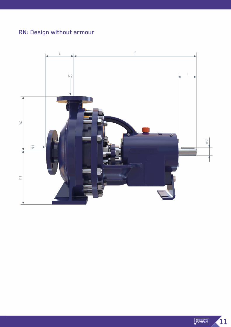
BB = Bearing bracket N2 = Pressure flange
Pumps & installation dimensions
Size BBPump dimensions Shaft end Flange
dimensions
a f h 1 h 2 ød I N1 N2
25-160 1 80 385 132 160 24 50 40 2525-200 1 80 385 160 180 24 50 40 2532-125 1 80 385 112 140 24 50 50 3232-160 1 80 385 132 160 24 50 50 3232-200 1 80 385 160 180 24 50 50 3240-125 1 80 385 112 140 24 50 65 4040-160 1 80 385 132 160 24 50 65 4040-200 1 100 385 160 180 24 50 65 4050-125 1 100 385 132 160 24 50 80 5050-160 1 100 385 160 180 24 50 80 5050-200 1 100 385 160 200 24 50 80 5065-125 1 100 385 160 180 24 50 100 6525-250 2 100 455 180 225 32 80 40 2532-250 2 100 500 180 225 32 80 50 3240-250 2 100 500 180 225 32 80 65 4040-315 2 125 500 200 250 32 80 65 4050-250 2 125 500 180 225 32 80 80 5050-315 2 125 500 225 280 32 80 80 5065-160 2 100 500 160 200 32 80 100 6565-200 2 100 500 180 225 32 80 100 6565-250 2 125 500 200 250 32 80 100 6580-160 2 125 500 180 225 32 80 125 8080-200 2 125 500 180 250 32 80 125 8080-250 2 125 500 225 280 32 80 125 80100-200 2 125 500 200 280 32 80 125 10065-315 3 125 530 225 280 42 110 100 6580-315 3 125 530 250 315 42 110 125 8080-400 3 125 530 280 355 42 110 125 80100-250 3 140 530 225 280 42 110 125 100100-315 3 140 530 250 315 42 110 125 100100-400 3 140 530 280 355 42 110 125 100125-250 3 140 530 250 355 42 110 150 125125-315 3 140 530 280 355 42 110 150 125125-400 3 140 530 315 400 42 110 150 125150-250 3 160 530 280 375 42 110 200 150150-315 4 160 670 280 400 48 110 200 150150-400 4 160 670 315 450 48 110 200 150150-500 4 180 670 375 500 48 110 200 150200-250 4 180 670 355 425 48 110 200 200200-315 4 180 670 355 450 48 110 250 200200-400 4 180 670 355 500 48 110 250 200250-315 4 250 670 400 560 48 110 300 250200-500 6 200 900 425 560 75 150 250 200250-400 6 250 900 425 600 75 150 300 250300-400 6 300 900 500 670 75 150 350 300400-500 7 340 1160 550 800 100 160 400 400
All dimensions are shown in millimetres.
11
RN: Design without armour
h2h1
a f
IN2
N1
ød
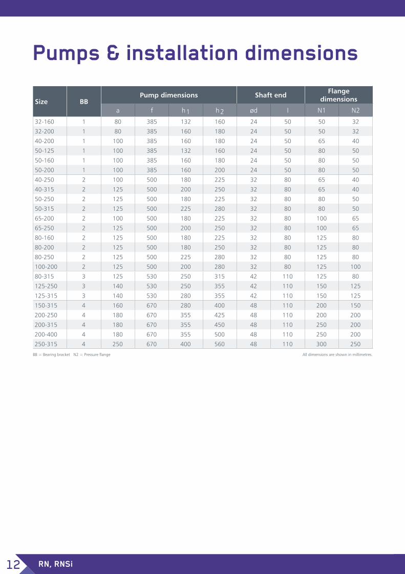
RN, RNSi12
Pumps & installation dimensions
Size BBPump dimensions Shaft end Flange
dimensions
a f h 1 h 2 ød I N1 N2
32-160 1 80 385 132 160 24 50 50 32
32-200 1 80 385 160 180 24 50 50 32
40-200 1 100 385 160 180 24 50 65 40
50-125 1 100 385 132 160 24 50 80 50
50-160 1 100 385 160 180 24 50 80 50
50-200 1 100 385 160 200 24 50 80 50
40-250 2 100 500 180 225 32 80 65 40
40-315 2 125 500 200 250 32 80 65 40
50-250 2 125 500 180 225 32 80 80 50
50-315 2 125 500 225 280 32 80 80 50
65-200 2 100 500 180 225 32 80 100 65
65-250 2 125 500 200 250 32 80 100 65
80-160 2 125 500 180 225 32 80 125 80
80-200 2 125 500 180 250 32 80 125 80
80-250 2 125 500 225 280 32 80 125 80
100-200 2 125 500 200 280 32 80 125 100
80-315 3 125 530 250 315 42 110 125 80
125-250 3 140 530 250 355 42 110 150 125
125-315 3 140 530 280 355 42 110 150 125
150-315 4 160 670 280 400 48 110 200 150
200-250 4 180 670 355 425 48 110 200 200
200-315 4 180 670 355 450 48 110 250 200
200-400 4 180 670 355 500 48 110 250 200
250-315 4 250 670 400 560 48 110 300 250
All dimensions are shown in millimetres.BB = Bearing bracket N2 = Pressure flange

13
RNSi: Design with armour
h2h1
a f
IN2
N1 ød

RN, RNSi14
Capacity ranges
Bearing bracket
4,4 10 20 50 100 200 500 1.000 2.000 5.000 10.000
50
100
500
1 10 20 50 100 200 500 1.000 4.0002 3 4 5
20
40
50
6070
30
8090
100
160
10
65/315
80/3
15
40/315
25/250
100/
200
32/250
80/1
60
50/2
50
65/2
00
80/200
65/250
65/1
60
50/315
40/2
50
50/3
15
80/2
50
32/200
32/160
25/200
65/1
25
40/125
25/160
32/125
50/200
50/1
60
42/200
50/125
42/160
4,4 10 20 50 100 200 500 1.000 2.000 5.000 10.000
10
20
50
100
200
500
1 10 20 50 100 200 500 1.000 4.0002 3 4 52
150
100
5040
30
20
10
45
3
400/
500*
200/
500
300/400
250/400
150/500
200-
250
150/400
200/
315
200/400
250/
315150/315
65/315
80/400
125/
400
100/
400
125/
250
100/
250
80/3
15
100/315
125/
315
150/250
40/315
25/25010
0/20
0
32/250
80/160
50/315
40/250
50/2
50
65/2
00
80/200
80/25065/250
65/160
32/200
32/160
25/200
50/160
50/20040/200
65/12550/125
40/125
25/160
32/125
40/160
H (
ft)
Pum
p h
ead
H (
m)
US. GPM
RN/RNSi: 50 Hz n = 1450 /min
Flow rate Q (m3/h)
H (
ft)
Pum
p h
ead
H (
m)
US. GPM
RN/RNSi: 50 Hz n = 2900 /min
Flow rate Q (m3/h)
4321 6
* Rotational speed n=980 1/min

15
4,4 10 20 50 100 200 500 1.000 2.000 5.000 10.000
10
20
50
100
500
200
100
50
40
30
20
10
5
4
31 10 20 50 100 200 500 1.000 4.0002 3 4 5
400/500**
300/400*
200/315
150/
400
250/
315150/315
200/
250
200/40080/400
100/
400
125/
250
100/
250
65/315
125/
400
125/315100/315
150/
250
80/3
1540/315
25/250
100/
200
32/250
80/1
60
50/2
50
65/20080/200
80/2
5065/250
65/1
60
50/315
40/250
32/200
32/160
25/200
65/1
25
40/125
25/160
32/125
40/160
50/20040/200
50/125
50/160
4,4 10 20 50 100 200 500 1.000 2.000 5.000 10.000
50
100
500
1 10 20 50 100 200 500 1.000 4.0002 3 4 5
20
40
50
30
100
200
10
50/315
25/250
100/
200
32/250
80/1
60
50/250
65/2
00
80/2
00
65/250
65/1
60
80/2
50
40/250
32/200
32/160
25/200
65/1
25
40/125
25/160
32/125
50/2
00
50/1
60
40/160
50/125
40/200
H (
ft)
Pum
p h
ead
H (
m)
US. GPM
RN/RNSi: 60 Hz n = 1750 /min
Flow rate Q (m3/h)
H (
ft)
Pum
p h
ead
H (
m)
US. GPM
RN/RNSi: 60 Hz n = 3500 /min
Flow rate Q (m3/h)
* Rotational speed n=1150 1/min
** n=1180 1/min

ITT RHEINHÜTTE Pumpen GmbH Rheingaustraße 96-98 D-65203 WiesbadenT +49 611 604-0 [email protected]
3.26.0001/001-0621_en_xy B.RN.en-GB.2021-06