ground source heat pump setting out horizontal groundworks
TRANSCRIPT

1
Ground Source Heat Pump – Setting Out Horizontal Groundworks Guidelines
These Guidelines have been set out to give an installer a better understanding of the common problems and space requirements of designing a ground array. The responsibility of ensuring this design is correct will always remain in the hands of the Installer.
Spire Renewables accepts no responsibility for the actions of personnel using the information contained in this manual, or any damages or costs arising from such use.
The contents of this guideline are the copyright of Spire Renewables. No part of this document may be reproduced or published in any form without the prior written consent of Spire Renewables.
Basic Overview
The ground array for a ground source heat pump is essentially its fuel source. Its design is 100% critical to the success of the installation. There must be sufficient pipe buried in the ground, and that pipe must be spread over a large enough area so energy extraction is sustainable. Energy used in the property cannot be extracted from the ground over time in greater quantities than is returned to the ground from solar irradiation or rainfall, otherwise the net ground temperature will drop resulting in the heat pump eventually failing.
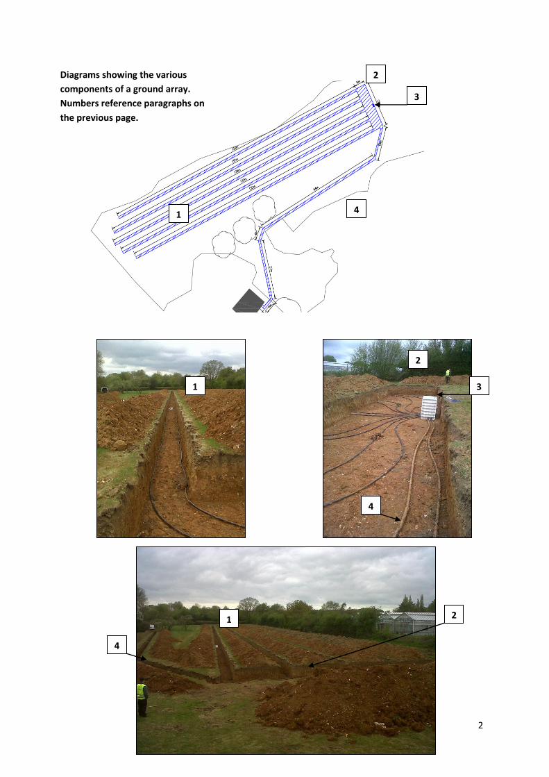
A horizontal ground array consists of four main components (please see the overleaf diagrams explaining this further):
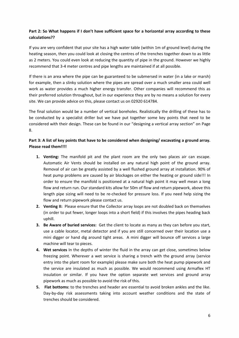
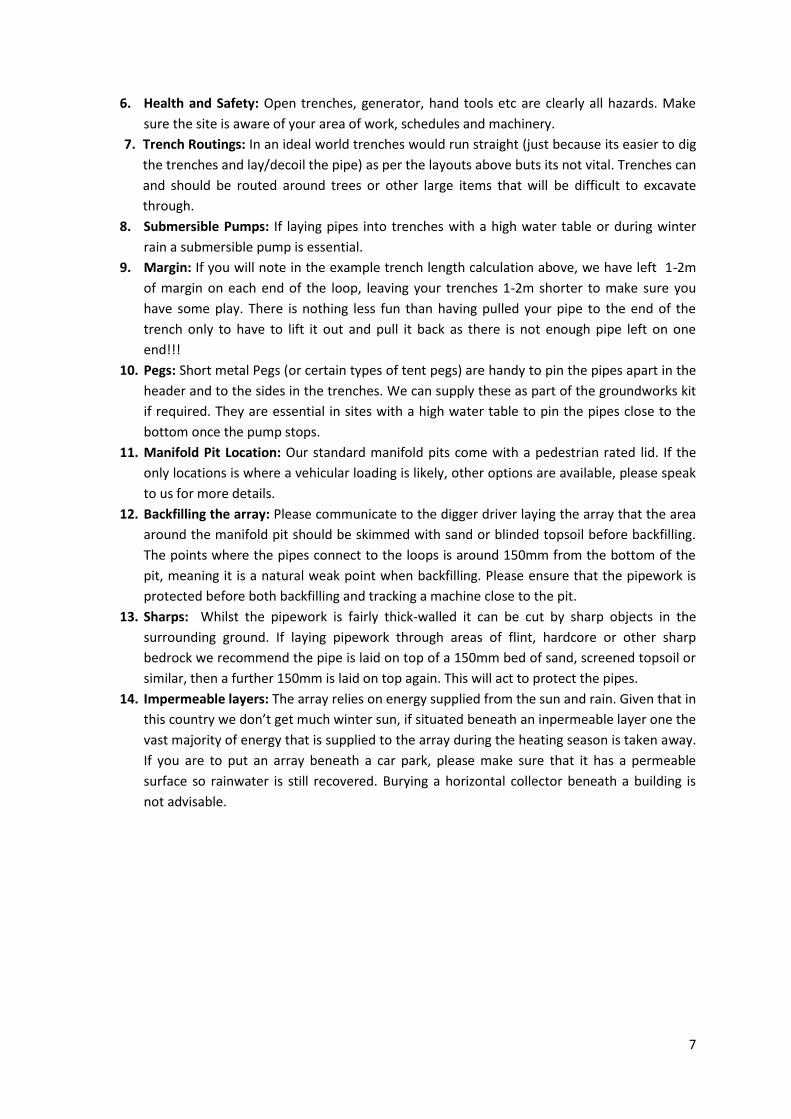
1. The Collector Array – A number of 40mm loops that run in individual trenches; dug 900mm to a metre wide and at least a metre deep. These collect the bulk of the energy from the ground. If suitable horizontal space is not available then the loops should be buried vertically using a drill rig (see Page 6 for more details).
2. The Header – an open area (normally 3-4m wide) set at the uphill end of the trenches so that the collector loops can be separated from one another as much as possible on their way back to the manifold.
3. The Manifold Pit – Each of the loops of the collector array run back to an individual pair of ports on the manifold pit. This is normally sat centrally in the open header. Each port of the manifold has a flow gauge and adjustor to enable flow to be balanced across the array. The manifold pit must sit higher (or at least on a level) than the collector array to allow for air venting (automatic air vents are supplied with the manifold).
4. The Flow and Return – The main pair of pipes running from the manifold and pit to the plant room. They are hypothetically the warmest and coldest pipes of the array so should have at least a minimum of a metre separation and be buried a meter underground either in a single meter wide trench or a pair of 300mm slot trenches. The diameter of these is dictated by the length of run from the plant room to the manifold pit (we can help with these calculations). If these pipes pass over a significant high point between the manifold pit and the plant room (both of which are vented) it may be necessary to install additional vents at this point too.
2
1.
2.
4.
3.
2.
1.
1
4.
2.
4.
Diagrams showing the various components of a ground array. Numbers reference paragraphs on the previous page.
3.

3
The next few pages of this document outline the logistics of laying out of a Horizontal Ground Array. If you are uncertain about whether you have sufficient room for a horizontal ground array, please follow the next steps below. If you are aware you definitely need a drilled array as you do not have the land area available please jump to Page 9. Please ensure that you read the key points section at the end of this document fully before proceeding:
Part 1: Do you have sufficient room for a horizontal array?
1. Quantity of collector pipe required: The minimum quantity of collector pipe for a horizontal array we would supply as our groundworks kit is as follows:
Heat Pump Output (kW) Total Length of Collector Pipe Required 6 400m 8 500m 10 600m 12 750m 14 900m
In certain areas containing permeable materials such as chalk or sand where groundwater will not be retained around the pipes for an extended period of time it may be advisable to add a minimum of 15% more collector to each of those stated lengths above. The MCS guidelines also provide an alternative simple way of calculating collector length.
2. Trench Length: The collector pipe is going to be laid in a number of trenches each 900mm-1000m wide (depending on available bucket size) and 1000mm deep. The trench length depends on the dimensions of the ground available for the array, and the number of trenches required dictates the number of ports on the manifold. Each trench has a flow and return pipe tucked up against each side as per the photos below, with the pipe looped at one end and both tails connected to the manifold. This therefore means that that likely best trenching options per system are as follows:
Heat Pump Output (kW) Trenching Options 6 2 x 100m, 4 x 50m, 8 x 25m 8 2 x 125m, 5 x 50m, 10 x 50m 10 3 x 100m, 6 x 50m, 12 3 x 125m, 6 x 62.5m 14 3 x150m, 6 x 75m

4
3. Trench Separation: The minimum separation we would recommend between trenches is 3m, but ideally 4m or above if space allows. This minimises thermal interference between the loops, and provides an area to pile excavated spoil between the trenches. This therefore enables all trenches to be open at one time – the pipe can then be laid and pressure tested in one hit before backfilling. The trenches should be a metre wide (or 900mm if that is the bucket size readily available) and at least a metre deep below finished ground level (have a conversation with the client/landscape architect first). We would recommend that your digger driver separates topsoil from the lower strata then backfills accordingly. It makes for much quicker recovery of a finished field.
So from the information above you ought to be able to work out the space you require for a ground array. A little worked example to help:
I need a 10kW heat pump to heat my house. My plot is 75m x 50m. I therefore need to bury 600m of collector pipe, or 4 loops of 150m.
My standard separation between trench centres is 4m (3m between the trench and a 1m wide trench) so I need a header 16m wide x 4m across (at its widest point, the header can be made smaller at the edges where there is less collector). My longest centre two trenches will therefore need to be 68m –
2m excess + 5m across the header + 68m there and back down the trench + a further 5m across the header and another 2m excess = 150m.
The next two trenches out will be 65m.
1m excess + 9m across the header to the trench start point + 65m there and back down the trench, a further 9m across the header back to the pit and a 1m excess = 150m).
Please review this in the diagram overleaf. The blue hatched area identifies 1m deep trenches.

5
Diagram showing the Worked example of a 10kW ground array (From the previous page)
6
Part 2: So What happens if I don’t have sufficient space for a horizontal array according to these calculations??
If you are very confident that your site has a high water table (within 1m of ground level) during the heating season, then you could look at closing the centres of the trenches together down to as little as 2 meters. You could even look at reducing the quantity of pipe in the ground. However we highly recommend that 3-4 meter centres and pipe lengths are maintained if at all possible.
If there is an area where the pipe can be guaranteed to be submersed in water (in a lake or marsh) for example, then a slinky solution where the pipes are spread over a much smaller area could well work as water provides a much higher energy transfer. Other companies will recommend this as their preferred solution throughout, but in our experience they are by no means a solution for every site. We can provide advice on this, please contact us on 02920 614784.
The final solution would be a number of vertical boreholes. Realistically the drilling of these has to be conducted by a specialist driller but we have put together some key points that need to be considered with their design. These can be found in our “designing a vertical array section” on Page 8.
Part 3: A list of key points that have to be considered when designing/ excavating a ground array. Please read them!!!!
1. Venting: The manifold pit and the plant room are the only two places air can escape. Automatic Air Vents should be installed on any natural high point of the ground array. Removal of air can be greatly assisted by a well flushed ground array at installation. 90% of heat pump problems are caused by air blockages on either the heating or ground side!!! In order to ensure the manifold is positioned at a natural high point it may well mean a long flow and return run. Our standard kits allow for 50m of flow and return pipework, above this length pipe sizing will need to be re-checked for pressure loss. If you need help sizing the flow and return pipework please contact us.
2. Venting II: Please ensure that the Collector array loops are not doubled back on themselves (in order to put fewer, longer loops into a short field) if this involves the pipes heading back uphill.
3. Be Aware of buried services: Get the client to locate as many as they can before you start, use a cable locator, metal detector and if you are still concerned over their location use a mini digger or hand dig around tight areas. A mini digger will bounce off services a large machine will tear to pieces.
4. Wet services In the depths of winter the fluid in the array can get close, sometimes below freezing point. Wherever a wet service is sharing a trench with the ground array (service entry into the plant room for example) please make sure both the heat pump pipework and the service are insulated as much as possible. We would recommend using Armaflex HT insulation or similar. If you have the option separate wet services and ground array pipework as much as possible to avoid the risk of this.
5. Flat bottoms: to the trenches and header are essential to avoid broken ankles and the like. Day-by-day risk assessments taking into account weather conditions and the state of trenches should be considered.
7
6. Health and Safety: Open trenches, generator, hand tools etc are clearly all hazards. Make sure the site is aware of your area of work, schedules and machinery.
7. Trench Routings: In an ideal world trenches would run straight (just because its easier to dig the trenches and lay/decoil the pipe) as per the layouts above buts its not vital. Trenches can and should be routed around trees or other large items that will be difficult to excavate through.
8. Submersible Pumps: If laying pipes into trenches with a high water table or during winter rain a submersible pump is essential.
9. Margin: If you will note in the example trench length calculation above, we have left 1-2m of margin on each end of the loop, leaving your trenches 1-2m shorter to make sure you have some play. There is nothing less fun than having pulled your pipe to the end of the trench only to have to lift it out and pull it back as there is not enough pipe left on one end!!!
10. Pegs: Short metal Pegs (or certain types of tent pegs) are handy to pin the pipes apart in the header and to the sides in the trenches. We can supply these as part of the groundworks kit if required. They are essential in sites with a high water table to pin the pipes close to the bottom once the pump stops.
11. Manifold Pit Location: Our standard manifold pits come with a pedestrian rated lid. If the only locations is where a vehicular loading is likely, other options are available, please speak to us for more details.
12. Backfilling the array: Please communicate to the digger driver laying the array that the area around the manifold pit should be skimmed with sand or blinded topsoil before backfilling. The points where the pipes connect to the loops is around 150mm from the bottom of the pit, meaning it is a natural weak point when backfilling. Please ensure that the pipework is protected before both backfilling and tracking a machine close to the pit.
13. Sharps: Whilst the pipework is fairly thick-walled it can be cut by sharp objects in the surrounding ground. If laying pipework through areas of flint, hardcore or other sharp bedrock we recommend the pipe is laid on top of a 150mm bed of sand, screened topsoil or similar, then a further 150mm is laid on top again. This will act to protect the pipes.
14. Impermeable layers: The array relies on energy supplied from the sun and rain. Given that in this country we don’t get much winter sun, if situated beneath an inpermeable layer one the
vast majority of energy that is supplied to the array during the heating season is taken away. If you are to put an array beneath a car park, please make sure that it has a permeable surface so rainwater is still recovered. Burying a horizontal collector beneath a building is not advisable.