hoshizaki counter showcase · hoshizaki counter showcase is intended for temporary food display....
TRANSCRIPT

NO. 74NA-574
ISSUED: AUG. 10, 2001
REVISED:
HOSHIZAKICOUNTER SHOWCASE
MODEL HNC-120AA-L/RHNC-150AA-L/RHNC-180AA-L/RHNC-210AA-L/R
SERVICE MANUAL

74NA5740108
CONTENTS PAGE
1. SAFETY INSTRUCTIONS ------------------------------------------------------------------------- 1
2. MODEL NAME--------------------------------------------------------------------------------------- 3
3. OPERATING INSTRUCTIONS-------------------------------------------------------------------- 4
4. SPECIFICATIONS ---------------------------------------------------------------------------------- 5
5. DIMENSIONS ---------------------------------------------------------------------------------------- 6[a] HNC-120AA-L ----------------------------------------------------------------------------------- 6[b] HNC-120AA-R ----------------------------------------------------------------------------------- 7[c] HNC-150AA-L ----------------------------------------------------------------------------------- 8[d] HNC-150AA-R ----------------------------------------------------------------------------------- 9[e] HNC-180AA-L ---------------------------------------------------------------------------------- 10[f] HNC-180AA-R ---------------------------------------------------------------------------------- 11[g] HNC-210AA-L ---------------------------------------------------------------------------------- 12[h] HNC-210AA-R ---------------------------------------------------------------------------------- 13
6. REFRIGERATION CIRCUIT ---------------------------------------------------------------------- 14
7. WIRING DIAGRAM --------------------------------------------------------------------------------- 15
8. CONSTRUCTION ---------------------------------------------------------------------------------- 16
9. REMOVAL AND REPLACEMENT ------------------------------------------------------------- 17[a] SIDE COVER -----------------------------------------------------------------------------------17[b] TOP COVER ------------------------------------------------------------------------------------ 17[c] COVER - UNIT ---------------------------------------------------------------------------------- 17[d] FRONT GLASS--------------------------------------------------------------------------------- 17[e] SIDE FRAME -----------------------------------------------------------------------------------18[f] CENTER FRAME ------------------------------------------------------------------------------ 18[g] HOLDER - EVAPORATOR PIPE -----------------------------------------------------------18[h] CONTROL BOX --------------------------------------------------------------------------------18[i] UNIT -----------------------------------------------------------------------------------------------19
10. REFRIGERANT SERVICE INFORMATION --------------------------------------------------20
11. CONSTANT PRESSURE EXPANSION VALVE AND REFRIGERANT CHARGE --21[a] SPECIFICATIONS -----------------------------------------------------------------------------21[b] FUNCTION--------------------------------------------------------------------------------------- 21[c] CONSTRUCTION ------------------------------------------------------------------------------ 21[d] REPLACEMENT ------------------------------------------------------------------------------- 22
12. SERVICE DIAGNOSIS --------------------------------------------------------------------------- 23
74NA5740108 1
1. SAFETY INSTRUCTIONS
The following instructions contain important safety precautions and should be strictly observed.The terms used here are defined as follows:
WARNING: There is a possibility of death or serious injury for the service person and a thirdparty or the user due to improper service operations or defects in servicedproducts.
CAUTION: There is a possibility of injury for the service person and a third party or the useror damage to their property* due to improper service operations or defects inserviced products.
* The term “damage to their property” here refers to extensive damage to household effects,houses and pets.
WARNING
1. Always ask the user to keep children away from the work area. They may be injured bytools or disassembled products.
2. When there is no need to energize the unit during disassembly or cleaning, be sure tounplug the unit or disconnect the main power supply before servicing the unit to preventelectric shocks.
3. If the unit must be energized for inspection of the electric circuit, use rubber gloves to avoidcontact with any live parts resulting in electric shocks.
4. Keep the following in mind when servicing the refrigeration circuit:
(1) Be sure to recover the refrigerant. Do not discharge it into the atmosphere. It willaffect the environment.
(2) Check for any flames in the vicinity, and ensure good ventilation.
(3) If the refrigerant should leak in servicing, immediately put out any fire used in thevicinity.
(4) When unbrazing the refrigeration circuit connections, check that the circuit is completelyevacuated. The refrigerant may produce a poisonous gas when coming in contactwith an open flame.
(5) Do not braze in an enclosed room to prevent carbon monoxide poisoning.
(6) In case of a refrigerant leak, locate and repair the leaking part completely. Leakedrefrigerant may produce a poisonous gas when coming in contact with an open flame.
(7) Before servicing, check the surface temperature of the refrigeration circuit to preventa burn.

74NA57401082
5. Keep the following in mind when making electrical connections:
(1) Check for proper grounding connections, and repair if necessary to prevent electricshocks.
(2) Always use service parts intended for the applicable model for replacement of defectiveparts. Use proper tools to secure the wiring. Otherwise abnormal operation or troublemay occur and cause electric leaks or fire.
(3) Check for proper part installations, wiring conditions and soldered or solderless terminalconnections to avoid fire, heat or electric shocks.
(4) Be sure to replace damaged or deteriorated power cords and lead wires to preventfire, heat or electric shocks.
(5) Cut-off lead wires must be bound using closed end connectors or the like, with theirclosed ends up to avoid entrance of moisture that could lead to electric leaks or fire.
(6) After servicing, always use a megohmmeter (DC500V) to check for the insulationresistance of at least 1 megohm between the live part (attachment plug) and thedead metal part (grounding terminal).
(7) Do not service the electrical parts with wet hands to prevent electric shocks.
(8) The capacitors used for the compressor and other components may be under highvoltage and should be discharged properly before servicing.
CAUTION
1. After servicing, always check for proper operation.

74NA5740108 3
2. MODEL NAME
H NC - 120 A A - R/LHigh Grade Unit Location
R: Unit on rightL: Unit on left
Counter ShowcaseHA model
Width (cm) Development Order120, 150, 180, 210 Starts from A
Unit on right
Unit on left

74NA57401084
3. OPERATING INSTRUCTIONS
IMPORTANT
Hoshizaki Counter Showcase is intended for temporary food display.Constructed with much glass, this showcase gives relatively insufficient heatinsulation and poor cooling performance compared with refrigerators in general.For safe and efficient operation, be sure to follow the instructions below.
1) Do not leave foods in the showcase after service hours, or they may dry or spoil. Foodsthat should not dry must be covered or wrapped up in a plastic film.
2) Store only pre-refrigerated items in the showcase. It takes longer for foods to cool in theshowcase than in a refrigerator.
3) Do not leave the Doors open or open them too frequently. The interior temperature mayrise, resulting in food deterioration.
4) Do not pack the showcase with foods. The cooling performance may reduce, resulting infood deterioration.
5) The showcase should not be exposed to direct sunlight or located next to ovens, grills orother high heat producing equipment. The interior temperature may rise, resulting in fooddeterioration.
6) The ambient temperature should not exceed 80°F (27°C). The cooling performance mayreduce, resulting in food deterioration.
7) The Food Mount can be used on either side. The food temperature is controllable byturning over the Food Mount to change the distance from the interior bottom.
Normal conditionWhen food temp. is too low For more intensive cooling
8) The maximum safe height for displaying food products is 3.5” (9cm) above the interiorbottom. Food products should not be placed above this height as they may not remaincold enough to avoid spoilage.

4. SPECIFICATIONS
MODEL HNC-120AA-L-R
HNC-150AA-L-R
HNC-180AA-L-R
HNC-210AA-L-R
AC SUPPLY VOLTAGEPOWER SUPPLY CAPACITYRATED AMPERAGESTARTING AMPERAGEELECTRIC CONSUMPTIONPOWER FACTOR
1 Phase 115V 60Hz0.47kVA (4.7A)3.0A13A195W56%
PULL DOWN TIME (10°C)SATURATION TEMPERATURE
Approx. 40 min. (Ambient Temp. 27°C, No Load)Approx. 4°C (Ambient Temp. 27°C, No Load)
NET CAPACITY 42 L 57 L 72 L 87 L1200 mm 1500 mm 1800 mm 2100 mmEXTERIOR DIMENSIONS (W)
(D)(H)
345 mm280 mm
845 mm 1145 mm 1445 mm 1745 mmINTERIOR DIMENSIONS (W)(D)(H)
288 mm (bottom)157 mm
EXTERIORINTERIORINSULATION
Glass, ABS Plastic, PVC Plastic, Galvanized SteelGlass, ABS Plastic, Stainless SteelPolyurethane Foam
REFRIGERATION SYSTEMDEFROST SYSTEM
Convection CoolingNoneHermetic 130W Model CE56Y-1ZUFin and Tube Type, Cooling Fan Motor x 1(UPPER) Bare Tube Type, (LOWER) Pipe on Sheet TypeConstant Pressure Expansion Valve
COMPRESSORCONDENSEREVAPORATORREFRIGERANT CONTROLREFRIGERANT TYPE / CHARGE R134a / 130 g R134a / 150 g R134a / 180 g R134a / 200 gELECTRIC CIRCUIT PROTECTIONCOMPRESSOR PROTECTION
Ground Fault Circuit Interrupter, Ground WireMotor Protector
SLIDING DOOR 2 pcs. 4 pcs.NET WEIGHT / GROSS WEIGHT 30 kg / 37 kg 36 kg / 45 kg 42 kg / 53 kg 48 kg / 61 kgPACKAGE Carton
1280 mm 1580 mm 1880 mm 2180 mmSHIPPING DIMENSIONS (W)(D)(H)
413 mm405 mm
CERTIFICATION To be NSF and UL certified3 pcs. 4 pcs. 5 pcs. 6 pcs.ACCESSORIES FOOD MOUNT
PLUGVINYL HOSE
JOINT
4 pcs.1 pc.2 pcs.
AMBIENT TEMP.VOLTAGE VARIATION
10 - 27°CRated voltage ±10%
* The electrical specifications were determined at an ambient temperature of 27°C according to the electrical appliancetechnical standards.
* The pull down time and saturation temperature were measured 20 mm above the food mount (normal position) locatedat the interior bottom center.
* The food temperature is controllable by turning over the food mounts.
74NA5740108 5

74NA57401086
5. DIMENSIONS
[a] HNC-120AA-L

74NA5740108 7
[b] HNC-120AA-R

74NA57401088
[c] HNC-150AA-L

74NA5740108 9
[d] HNC-150AA-R

74NA574010810
[e] HNC-180AA-L

74NA5740108 11
[f] HNC-180AA-R

74NA574010812
[g] HNC-210AA-L

74NA5740108 13
[h] HNC-210AA-R
74NA574010814
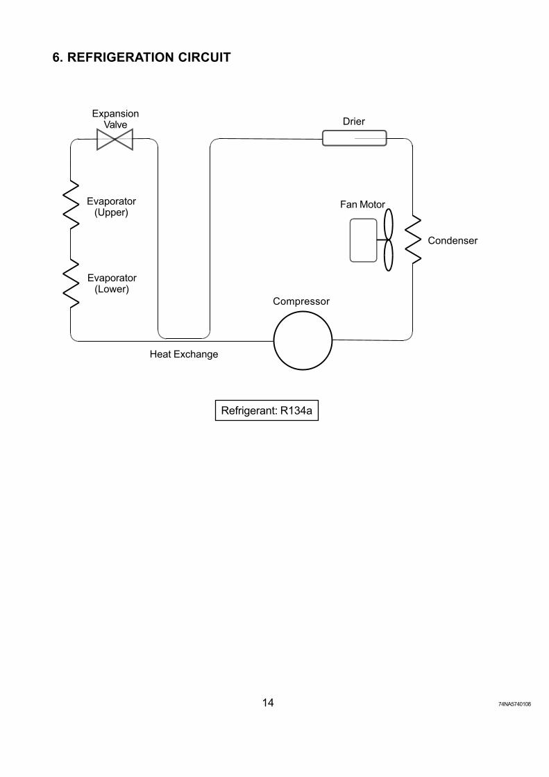
6. REFRIGERATION CIRCUIT
Refrigerant: R134a
Heat Exchange
Condenser
DrierExpansion
Valve
Evaporator(Upper)
Evaporator(Lower)
Fan Motor
Compressor
74NA5740108 15
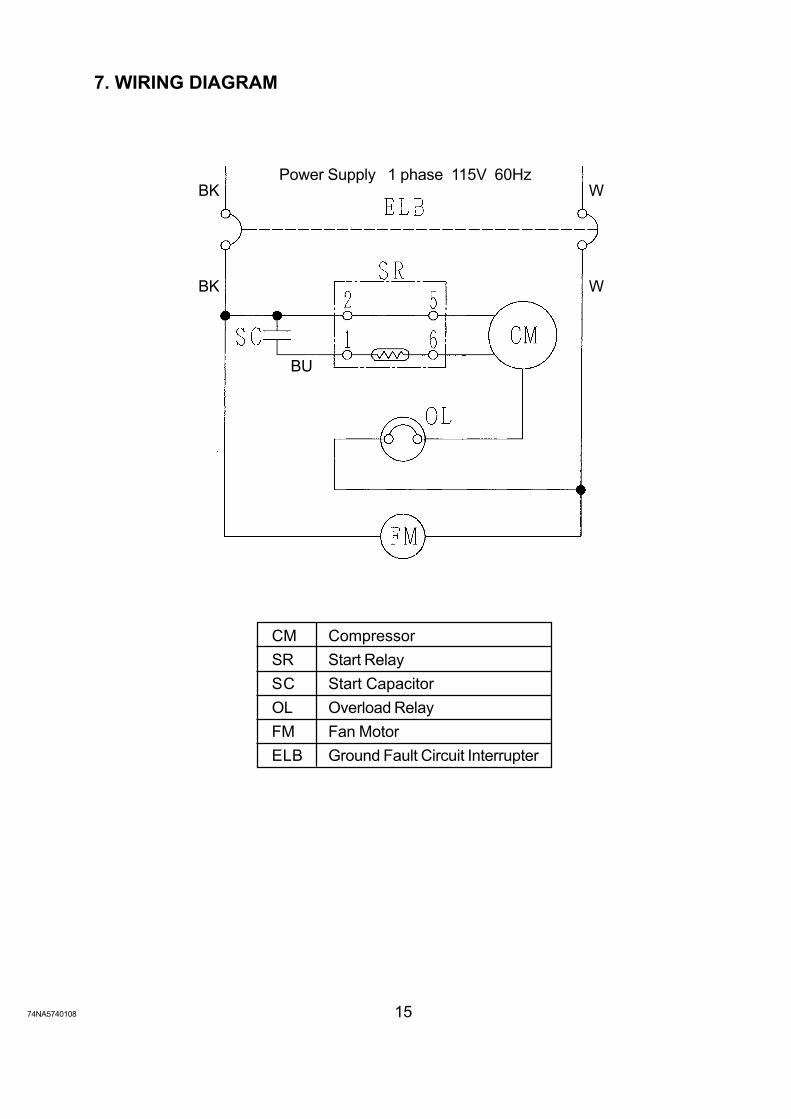
7. WIRING DIAGRAM
CM Compressor
SR Start Relay
SC Start Capacitor
OL Overload Relay
FM Fan Motor
ELB Ground Fault Circuit Interrupter
Power Supply 1 phase 115V 60Hz BK W
BK W
BU

74NA574010816
8. CONSTRUCTION
Sliding DoorFood Mount
Cover - Unit
Side Cover
Side Frame
Top Cover
Unit
Evaporator Pipe
Front Glass
Holder - Evaporator PipeCenter Frame
Louver
Ground FaultCircuit Interrupter
Control Box

74NA5740108 17
9. REMOVAL AND REPLACEMENT
CAUTION
1. Be sure to unplug the showcase before removing or replacing the parts.
2. Handle the glass parts with care.
[a] SIDE COVER
Remove the Cap from the Side Cover, the machine screw inside and the two machine screws(black) at the bottom.
[b] TOP COVER
Remove the Sliding Door and Side Cover.1) The Top Cover is hooked and fixed on the
Top Frame (aluminum).2) Lift up and unhook the rear end of the Top
Cover.3) When the rear part is lifted off, move it forward
to unhook and remove the front part.
The Top Cover is tightly hooked on the Top Frameand will not come off easily. Remove it with careto avoid injury. To replace, reverse the removalprocedure.
[c] COVER - UNIT
Remove the Sliding Door, Side Cover and TopCover. Remove the two machine screwssecuring the top of the Cover - Unit, and take offthe Cover.
[d] FRONT GLASS
Remove the Sliding Door, Side Cover, Top Coverand Cover - Unit. Remove the Holder - Framesecured on the Top Frame with machine screws.Lift the Front Glass off the bottom fit.
The side interior of the Front Glass is sealed withsilicone sealant (black). Be sure to re-seal it atreplacement.
Top Cover①
②
③
Top Frame
Fig. 1
Fig. 2
Gasket Holder - Frame
Top Frame
Front Glass

74NA574010818
[e] SIDE FRAME
Remove the Sliding Door, Side Cover and Top Cover. Unbind the wiring on the Side Frame.Remove the two screws securing the Top Frame and the top of the Side Frame. Lift the SideFrame off the bottom fit.
[f] CENTER FRAME (Except HNC-120 type)
Remove the two flat head machine screws(black) securing the Center Frame to the rearand the two machine screws securing the CenterFrame to the Top Frame. Tilt the Center Frameand release it from the fit.
[g] HOLDER - EVAPORATOR PIPE
Remove the truss head tapping screw (4 x 25)from the bottom. Take off the Center Frame. Becareful with the Evaporator Pipe. It will bereleased and hang down. Remove the trusshead tapping screw (4 x 10) from the bottom.
[h] CONTROL BOX
Remove the two machine screws indicated. Pullout the Control Box.
Fig. 3
Fig. 5
Fig. 4
Truss Head TappingScrew 4 x 5
Truss Head TappingScrew 4 x 10
Holder -Evaporator Pipe
Evaporator Pipe

74NA5740108 19
[i] UNIT
Remove the Sliding Door, Side Cover, Top Cover, Cover - Unit and Side Frame. Take off theCompressor Terminal Cover and remove the Starter and Motor Protector. Uninsulate theExpansion Valve and unbraze the Inlet or Outlet Pipe with a gas burner (see “11. CONSTANTPRESSURE EXPANSION VALVE AND REFRIGERANT CHARGE”).Unbraze the part shown in Fig. 6. Remove the four machine screws securing the Unit Base.The whole unit can be pulled out.
Fig. 6
View A

74NA574010820
10. REFRIGERANT SERVICE INFORMATION
1) Allowable Compressor Opening Time and Prevention of Lubricant Mixture [R134a]
The compressor must not be opened more than 30 minutes in replacement or service. Donot mix lubricants of different compressors even if both are charged with R134a, exceptwhen they uses the same lubricant.
2) Treatment for Refrigerant Leak [R134a]
If a refrigerant leak occurs in the low side of an ice maker charged with R134a, air may bedrawn in. Even if the low side pressure is higher than the atmospheric pressure in normaloperation, a continuous refrigerant leak will eventually lower the low side pressure below theatmospheric pressure and will cause air suction. Air contains a large amount of moisture,and ester easily absorbs a lot of moisture. If an ice maker charged with R134a has possiblydrawn in air, the drier must be replaced. Be sure to use a drier designed for R134a.
3) Handling of Handy Flux [R134a]
Repair of the refrigerant circuit needs brazing. It is no problem to use the same handy fluxthat has been used for the current refrigerants. However, its entrance into the refrigerantcircuit should be avoided as much as possible.
4) Oil for Processing of Copper Tubing [R134a]
When processing the copper tubing for service, wipe off oil, if any used, by using alcohol orthe like. Do not use too much oil and let it into the tubing, or wax contained in the oil will clogthe capillary tubing.
5) Service Parts for R134a
Some parts used for refrigerants other than R134a are similar to those for R134a. But neveruse any parts unless they are specified for R134a because their endurance against therefrigerant have not been evaluated. Also, for R134a, do not use any parts that have beenused for other refrigerants. Otherwise, wax and chlorine remaining on the parts may adverselyaffect R134a.
6) Replacement Copper Tubing [R134a]
The copper tubes currently in use are available for R134a. But do not use them if oily inside.The residual oil in copper tubes should be as little as possible. (Low residual oil type coppertubes are used in the shipped units.)
7) Evacuation, Vacuum Pump and Refrigerant Charge [R134a]
Never allow the oil in the vacuum pump to flow backward. The vacuum level and vacuumpump may be the same as those for the current refrigerants. However, the rubber hose andgauge manifold to be used for evacuation and refrigerant charge should be exclusively forR134a.

74NA5740108 21
8) Refrigerant Leak Check
Refrigerant leaks can be detected by charging the unit with a little refrigerant, raising thepressure with nitrogen and using an electric detector. Do not use air or oxygen instead ofnitrogen for this purpose, or rise in pressure as well as in temperature may cause R134a tosuddenly react with oxygen and explode. Be sure to use nitrogen to prevent explosion.
11. CONSTANT PRESSURE EXPANSION VALVE AND REFRIGERANTCHARGE
[a] SPECIFICATIONS
Model: HYP-2-5QHD-5Manufacturer: Fuji KokiPart Number: 447283-04Refrigerant: R134aAdjustment Range: 0.01 - 0.3MPaPressure Rise by Adjusting Screw: 0.039 - 0.049MPa / turn
[b] FUNCTION
When the low side pressure drops, the Constant Pressure Expansion Valve opens and letsthe refrigerant flow to keep a constant pressure.
[c] CONSTRUCTION
Fig. 7
IN (High Pressure)
Needle ValveCap
AdjustingScrew
AdjustingSpring
Diaphragm
WorkingBar
Inner Spring
OUT (Low Pressure)
Low Pressure
Close Open
DOWN UP

74NA574010822
[d] REPLACEMENT
WARNING
Always protect the valve body by using a damp cloth to prevent the valve fromoverheating. Do not braze with the valve body exceeding 230°F (110°C).
IMPORTANT
Always install a new Drier every time the sealed refrigeration system is opened.Do not replace the Drier until after all other repairs or replacement have beenmade.
1) Recover the refrigerant (R134a) and store it in an approved container.
2) Remove the Insulation Cover and Cap from the Expansion Valve.
3) Remove the Expansion Valve by heating the Inlet and Outlet Pipes with a gas burner.
Fig. 8
Wet Floorcloth
Burner
Burner
Drier
Evaporator

74NA5740108 23
PROBLEM[1] Showcase will not
start.
[2] Poor coolingperformance
[3] Dry foods
[4] Frosting
POSSIBLE CAUSE1. Ground Fault Cirucit Interrupter in
OFF position.2. Unplugged.3. Supply voltage too low.
4. No power supply to the wall outlet.(Breaker or fuse blown out.)
5. Electrical circuit open or badcontacts.
6. Motor Protector tripped.1. Gas leaks.2. Fan Motor defective.3. Condenser and/or Air Filter
clogged.4. Condenser air inlet blocked.5. Exposed to direct sunlight.6. Located next to a high heat
producing equipment.7. Doors opened too frequently or
left open.8. Packed with foods, or warm or
hot foods inside.9. Ambient temperature exceeding
80°F (27°C).1. Foods have been stored from the
previous day.2. Foods have been stored for a long
time.1. [Exterior] Relative humidity
exceeding 60%.2. [Interior] Doors opened too
frequently or left open.
REMEDY1. Turn ON.
2. Plug in.3. Plug into a separate receptacle
of 115V±10%.4. Correct.
5. Correct.
6. Ventilate and reset Fan Motor.1. Repair the leaks and recharge.2. Replace.3. Clean.
4 - 9. Instruct the user oncharacteristics and properuse of the showcase.
1 - 2. Instruct the user oncharacteristics and properuse of the showcase.
1 - 2. Instruct the user oncharacteristics and properuse of the showcase.Wipe off excessive frost witha soft cloth.
12. SERVICE DIAGNOSIS

HOSHIZAKI ELECTRIC CO., LTD.3-16 MINAMIYAKATA, SAKAE, TOYOAKE,AICHI 470-1194 JAPANPHONE: 0562-97-2111
HOSHIZAKI AMERICA, INC.618 HIGHWAY 74 SOUTH, PEACHTREE CITY,GEORGIA 30269 U.S.A.PHONE: 770-487-2331