hour 1: concept review / overview prs questions – possible exam questions hour 2 ·...
TRANSCRIPT
1P31
Class 31: Outline
Hour 1: Concept Review / Overview PRS Questions – possible exam questions
Hour 2: Sample Exam
Yell if you have any questions

2P31
Exam 3 Topics • Faraday’s Law • Self Inductance
• Energy Stored in Inductor/Magnetic Field • Circuits
• LR Circuits • Undriven (R)LC Circuits • Driven RLC Circuits
• Displacement Current • Poynting Vector
NO: B Materials, Transformers, Mutual Inductance, EM Waves

3P31
General Exam Suggestions • You should be able to complete every problem
• If you are confused, ask • If it seems too hard, you aren’t thinking enough • Look for hints in other problems • If you are doing math, you’re doing too much
• Read directions completely (before & after) • Write down what you know before starting • Draw pictures, define (label) variables
• Make sure that unknowns drop out of solution • Don’t forget units!

4P31
Maxwell’s Equations
0
0 0 0
(Gauss's Law)
(Faraday's Law)
0 (Magnetic Gauss's Law)
(Ampere-Maxwell Law)
( (Lorentz force Law)
in
S
B
C
S
E enc
C
Qd
dd dt
d
dd I dt
q
ε
µ µ ε
⋅ =
Φ ⋅ = −
⋅ =
Φ ⋅ = +
= + ×
∫∫
∫
∫∫
∫
E A
E s
B A
B s
F E v B)
5P31
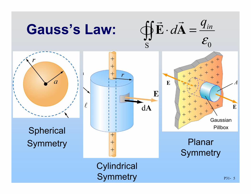
Gauss’s Law: 0S
inqd ε
⋅ =∫∫ E A
Spherical Symmetry
Cylindrical Symmetry
Planar Symmetry
Gaussian Pillbox

I
6P31
= 2 Current Sheets
Ampere’s Law: .∫ =⋅ encId 0µsB
B
B
X X X
X
X
X X
X
X X X
X
X
X X
X
X X X X X X X X X X X X
B
Long Circular
Symmetry (Infinite) Current Sheet
Solenoid
Torus/Coax

7P31
Faraday’s Law of Induction
( )cos
Bdd N dt dN BA dt
θ
ε Φ = ⋅ = −
= −
∫ E s
Induced EMF is in direction that opposes the change in flux that caused it
Lenz’s Law: Ramp B Rotate area
in field
Moving bar, entering field

8P31
PRS Questions: Faraday’s & Lenz’s Law
Class 21
9P31
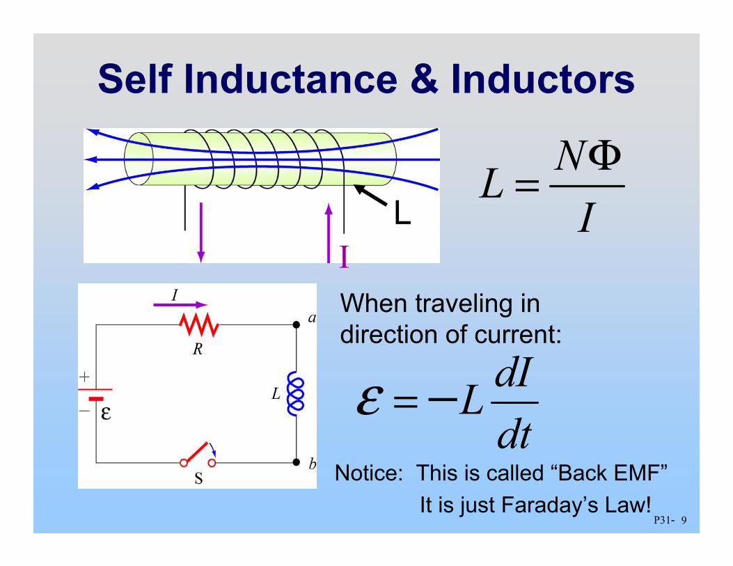
Self Inductance & Inductors
dIL dt
ε = −
I L
NL I Φ =
When traveling in direction of current:
Notice: This is called “Back EMF” It is just Faraday’s Law!
10P31-
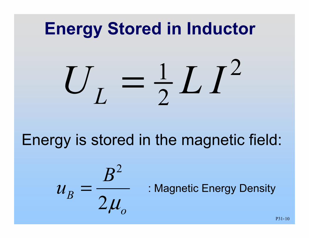
Energy Stored in Inductor
21 2LU L I =
: Magnetic Energy Density
Energy is stored in the magnetic field:
2
2B o
B u µ
=
11P31-
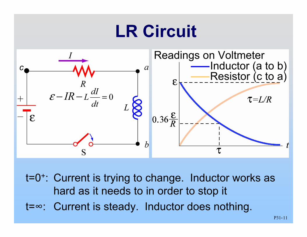
LR Circuit
t=0+: Current is trying to change. Inductor works as hard as it needs to in order to stop it
t=∞: Current is steady. Inductor does nothing.
Readings on VoltmeterInductor (a to b)Resistor (c to a)
c
0dIL dt
IRε =− −

12P31-
General Comment: LR/RC All Quantities Either:
( )/ Final Value( ) Value 1 tt e τ−= − /
0Value( ) Value tt e τ−=
τ can be obtained from differential equation (prefactor on d/dt) e.g. τ = L/R or τ = RC

13P31-
PRS Questions: Inductors & LR Circuits
Classes 23, 25
14P31-
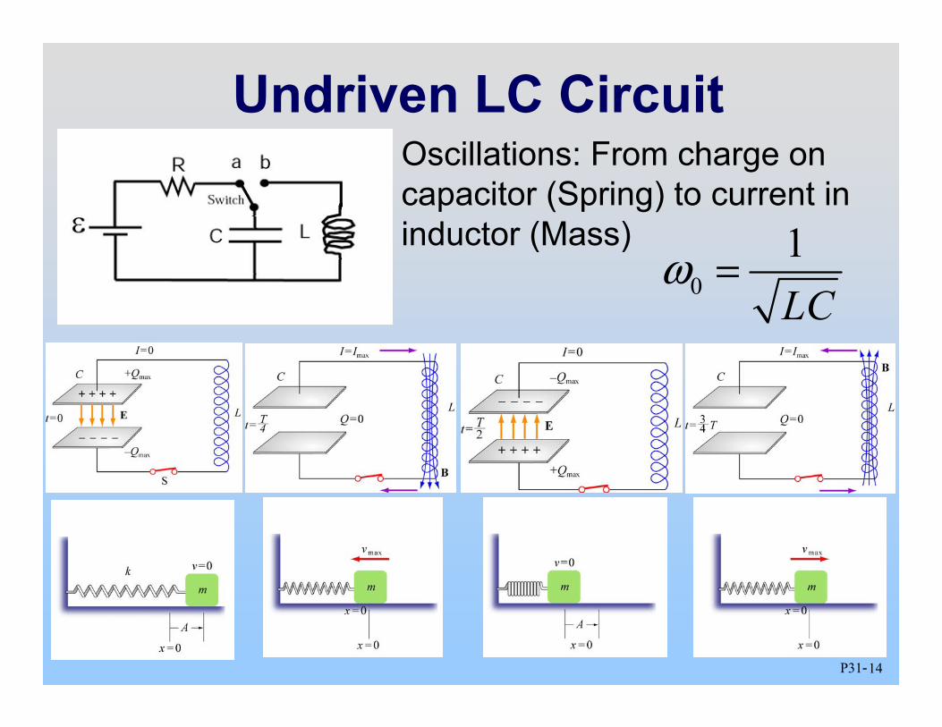
Undriven LC Circuit Oscillations: From charge on capacitor (Spring) to current in inductor (Mass)
0 1 LC
ω =

15P31-
Damped LC Oscillations
Resistor dissipates energy and system rings down over time
LQ n R
ωπ= =

16P31-
PRS Questions: Undriven RLC Circuits
Class 25

AC Circuits: Summary
Element V vs I0 Current vs.
Voltage
Resistance-Reactance
(Impedance)
Resistor 0 0V R = I R In Phase R = R
Capacitor 0 0C
IV ωC
= Leads (90º) 1XC ωC
=
Inductor 0 0LV I ωL= Lags (90º) X L = ωL
L32 - 17

18P31-
Driven RLC Series Circuit
Now Solve: S R L CV V V V= + +
I(t) 0I 0RV
0LV
0CV
0SV
Now we just need to read the phasor diagram!
VS

19P31-
Driven RLC Series Circuit
0I 0RV
0LV
0CV
0SV
2 2 2 2 0 0 0 0 0 0( ) ( )S R L C L CV V V V I R X X I Z = + − = + − ≡
ϕ
1tan L CX X
Rφ − −⎛ ⎞ = ⎜ ⎟
⎝ ⎠ 2 2( )L CZ R X X= + −0
0 SVI Z
=
( )0 sinS SV V tω=
0( ) sin( )I t I tω ϕ= −
Impedance

20P31-
Plot I, V’s vs. Time
0 1 2 3 0
+φ
-π/2 +π/2
V S
Time (Periods)
0V C
0V L
0V R
0I ( )
( )
( )
( )
( )
0
0
0 2
0 2
0
( ) sin
( ) sin
( ) sin
( ) sin
( ) sin
R
L L
C C
S S
I t I t
V t I R t
V t I X t
V t I X t
V t V t
π
π
ω
ω
ω
ω
ω ϕ
=
=
= +
= −
= +
1tan L CX X
Rφ − −⎛ ⎞ = ⎜ ⎟
⎝ ⎠
21P31-
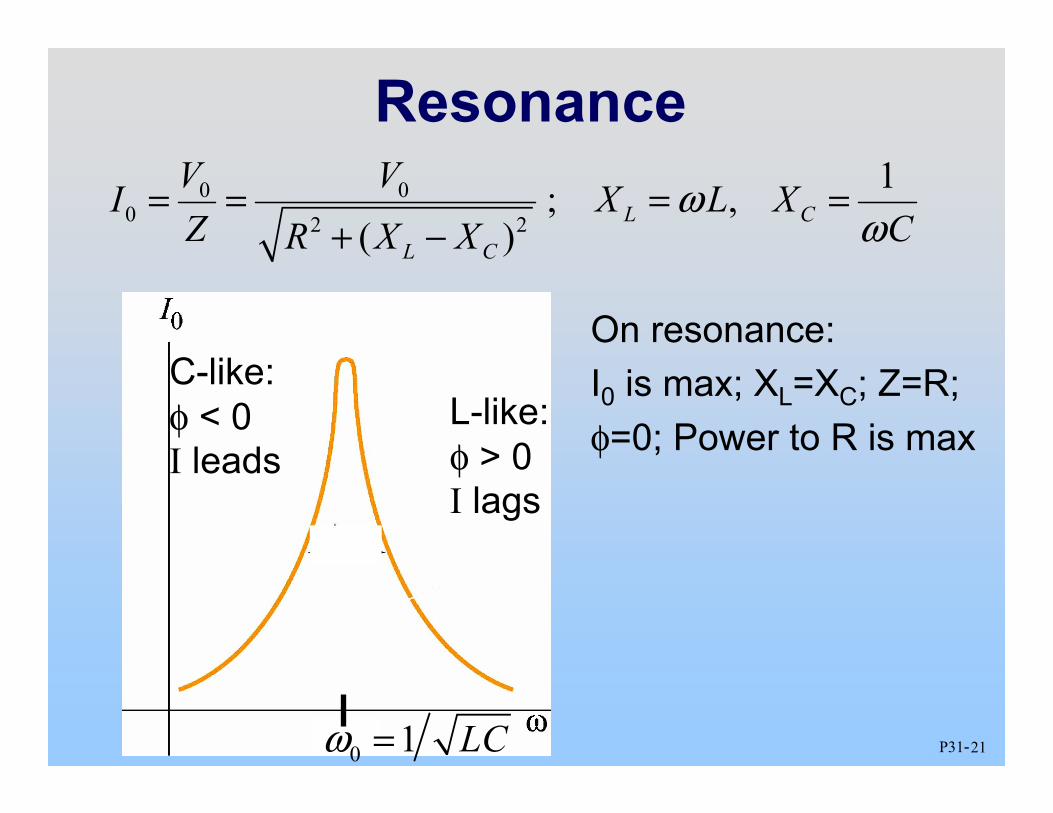
Resonance 0 0
0 2 2
1; , ( )
L C
L C
V VI X L XZ CR X X
ω ω
= = = = + −
C-like: φ < 0 I leads
0 1 LCω =
L-like: φ > 0 I lags
On resonance: I0 is max; XL=XC; Z=R; φ=0; Power to R is max

22P31-
Average Power: Resistor
( )
2
2 2 0
2 2 0
2 1 0 2
( ) sin ( )
sin ( )
P I t R
I t R
I R t
I R
ω ϕ ω ϕ
< > =< > =< − >
= < − >
=

23P31-
PRS Questions: Driven RLC Circuits
Class 26

24P31-
Displacement Current
0 E
d ddQ I
dt dtε Φ = ≡
0 0 0
E
QE Q EA A
ε εε
= ⇒ = = Φ
0
0 0 0
( )encl d C
E encl
d I I
dI dt
µ
µ µ ε
⋅ = +
Φ = +
∫ B s
Capacitors, EM Waves

25P31-
Energy Flow
0µ × = E BS
Poynting vector:
• (Dis)charging C, L • Resistor (always in) • EM Radiation
26P31-
PRS Questions: Displacement/Poynting
Class 28

27P31-
SAMPLE EXAM:
The real exam has 8 concept, 3 analytical questions
28P31-
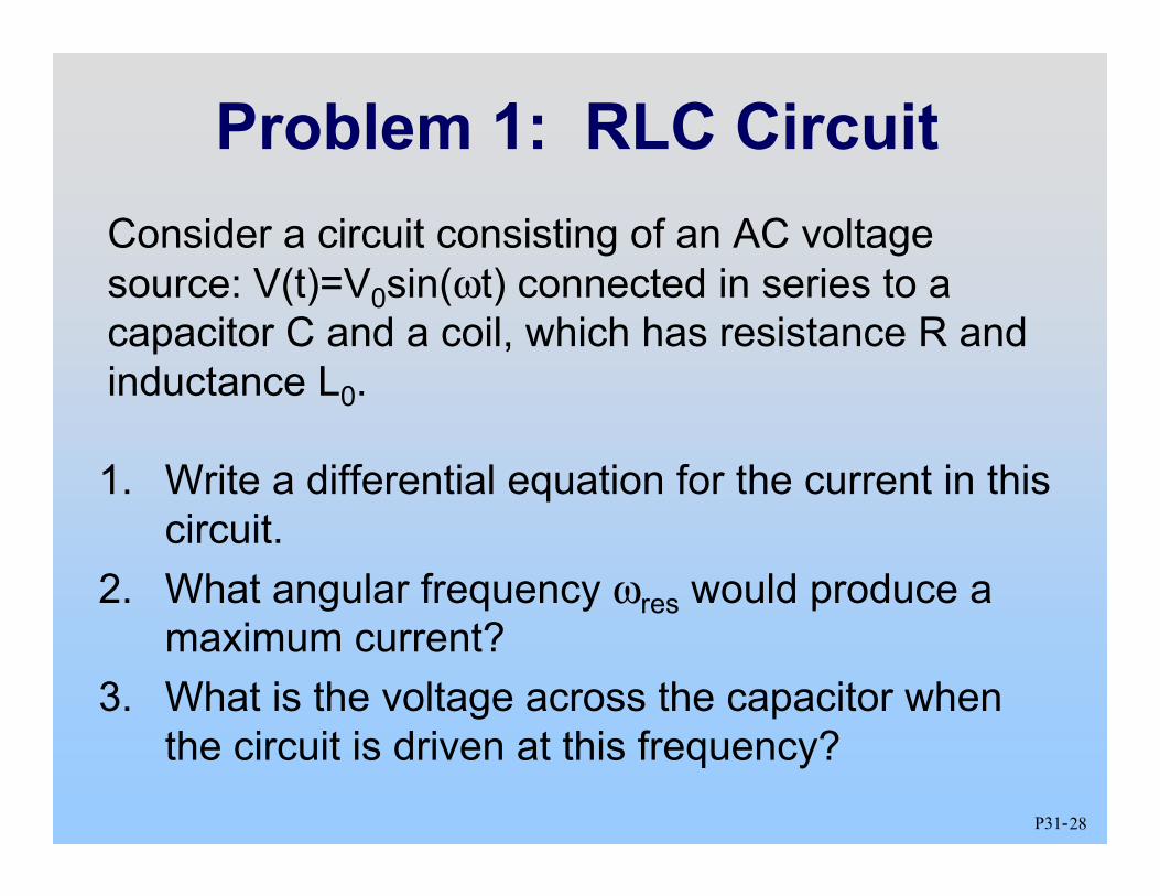
Problem 1: RLC Circuit
1. Write a differential equation for the current in this circuit.
2. What angular frequency ωres would produce a maximum current?
3. What is the voltage across the capacitor when the circuit is driven at this frequency?
Consider a circuit consisting of an AC voltage source: V(t)=V0sin(ωt) connected in series to a capacitor C and a coil, which has resistance R and inductance L0.

29P31-
Solution 1: RLC Circuit
2. Maximum current on resonance:
( )
2
2
0
0
cos
S
S
dI QV IR L dt C
dI d I I dR L Vdt dt C dt
V tω ω
− − − =
+ + =
=( )0 sinSV V tω=
1. Differential Eqn:
0
1 res L C
ω =
30P31-
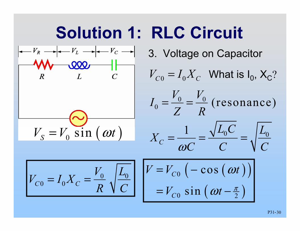
Solution 1: RLC Circuit
0 0C CV I X =
( )0 sinSV V tω=
3. Voltage on Capacitor
What is I0, XC?
0 0 0 (resonance) V VI
Z R = =
0 01 C
L C LX C C Cω
= = =
0 0 0 0C C
V LV I X R C
= = ( )( )
( ) 0
0 2
cos
sin C
C
V V t
V t π
ω
ω
= −
= −

31P31-
Problem 1, Part 2: RLC Circuit
4. Did the inductance increase or decrease? 5. Is the new resonance frequency larger, smaller
or the same as before? 6. Now drive the new circuit with the original ωres.
Does the current peak before, after, or at the same time as the supply voltage?
Continue considering that LRC circuit. Insert an iron bar into the coil. Its inductance changes by a factor of 5 to L=Lcore

32P31-
4. Putting in an iron core INCREASES the inductance
5. The new resonance frequency is smaller
6. If we drive at the original resonance frequency then we are now driving ABOVE the resonance frequency. That means we are inductor like, which means that the current lags the voltage.
Solution 1, Part 2: RLC Circuit

33P31-
Problem 2: Self-Inductance
The above inductor consists of two solenoids (radius b, n turns/meter, and radius a, 3n turns/meter) attached together such that the current pictured goes counter-clockwise in both of them according to the observer. What is the self inductance of the above inductor?
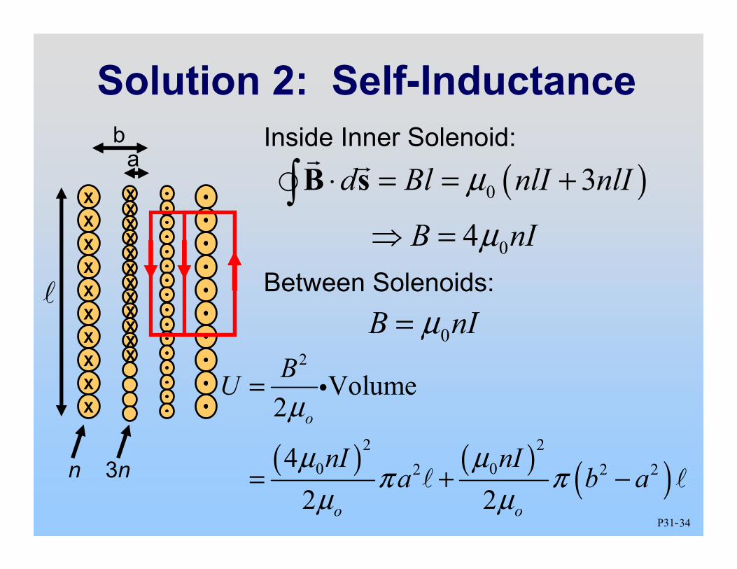
34P31-
Solution 2: Self-Inductance b
X X X X X X X X X X
X X X X X X X X X X X X X X X X
a
n 3n
Inside Inner Solenoid:
( )0
0
3
4
d Bl nlI nlI
B nI
µ
µ
⋅ = = +
⇒ = ∫ B s
Between Solenoids:
0B nI µ=
( ) ( ) ( )
2
2 2 0 02 2 2
Volume 2
4 2 2
o
o o
BU
nI nI a b a
µ
µ µπ π
µ µ
=
= + −
i

35P31-
Solution 2: Self-Inductance b
X X X X X X X X X X
X X X X X X X X X X X X X X X X
a
n 3n
( ) { } 2
0 2 215 2 o
nIU a b
µ π
µ = +
21 2U L I =
( ) { } 2
0 2 215 o
nL a b
µ π
µ ⇒ = +
Could also have used: NL I Φ =

36P31-
Problem 3: Pie Wedge
1. If the angle θ decreases in time (the bar is falling), what is the direction of current?
2. If θ = θ(t), what is the rate of change of magnetic flux through the pie-shaped circuit?
Consider the following pie shaped circuit. The arm is free to pivot about the center, P, and has mass m and resistance R.

37P31-
Solution 3: Pie Wedge
2) θ = θ(t), rate of change of magnetic flux?
1) Direction of I?
Lenz’s Law says: try to oppose decreasing flux
I Counter-Clockwise (B out)
2 2
2 2 aA a θ θπ
π ⎛ ⎞ = =⎜ ⎟⎝ ⎠
( ) 2
2 Bd d d aBA B
dt dt dt θΦ = =
2
2 Ba d
dt θ =

38P31-
Problem 3, Part 2: Pie Wedge 3. What is the magnetic force on
the bar (magnitude and direction – indicated on figure)
4. What torque does this create about P? (HINT: Assume force acts at bar center)

39P31-
Solution 3, Part 2: Pie Wedge
4) Torque?
3) Magnetic Force?
2 a Fτ= × ⇒ =τ r F
d Id= ×F s B
2 4
4 B a d
R dt
θ =
F IaB =
(Dir. as pictured) 2 3
2 B a d F R dt
θ =
1 BdI R R dt
ε Φ = = 21
2 Ba d
R dt θ =
(out of page)

40P31-
Problem 4: RLC Circuit
1. What energy is currently stored in the magnetic field of the inductor?
2. At time t = 0, the switch S is thrown to position b. By applying Faraday's Law to the bottom loop of the above circuit, obtain a differential equation for the behavior of charge Q on the capacitor with time.
The switch has been in position a for a long time. The capacitor is uncharged.

41P31-
Solution 4: RLC Circuit 1. Energy Stored in Inductor
2 21 1
2 2 U L I L
R
ε⎛ ⎞ = = ⎜ ⎟⎝ ⎠
2. Write Differential Equation
I
0dI QL dt C
− − = 2
2 0dQ d Q QI Ldt dt C
= ⇒ + =
+Q

42P31-
Problem 4, Part 2: RLC Circuit 3. Write down an explicit
solution for Q(t) that satisfies your differential equation above and the initial conditions of this problem.
4. How long after t = 0 does it take for the electrical energy stored in the capacitor to reach its first maximum, in terms of the quantities given? At that time, what is the energy stored in the inductor? In the capacitor?

43P31-
Solution 4: RLC Circuit 3. Solution for Q(t): ( )max ( ) sin Q t Q tω=
4. Time to charge capacitor
1 LC
ω = max 0Q I
R
εω = =
Charge 2 2
4 2 T LC T LC Tπ ππ
ω = = ⇒ = =
Energy in inductor = 0
Energy in capacitor = Initial Energy: 21
2 U L
R
ε⎛ ⎞ = ⎜ ⎟⎝ ⎠
⇒ max LCQ R
ε =

44P31-
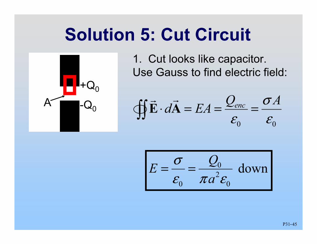
Problem 5: Cut Circuit
1. After a time t = t0, a charge Q = Q0 accumulates at the top of the break and Q= -Q0 at the bottom. What is the electric field inside the break?
2. What is the magnetic field, B, inside the break as a function of radius r<a?
Consider the circuit at left: A battery (EMF ε) and a resistor wired with very thick wire of radius a. At time t=0, a thin break is made in the wire (thickness d).
45P31-
Solution 5: Cut Circuit 1. Cut looks like capacitor. Use Gauss to find electric field:
0 0
encQ Ad EA σ
ε ε ⋅ = = =∫∫ E A
+Q0
-Q0A
0 2
0 0
downQE a
σ ε π ε
= =

46P31-
Solution 5: Cut Circuit 2. Find B field using Ampere’s Law
2 2 0 0 0
E d
d d dE I E r rdt dt dt
ε ε π ε πΦ = = = +Q0
-Q0
0 2
0
QE aπ ε
=
r
( ) 2
0 0 0 0 22 enc d d
dQrd B r I I I a dt
π µ µ µ⋅ = = + = =∫ B s
2 0 0 2
0
Qd r dt a
ε π π ε ⎛ ⎞
= ⎜ ⎟ ⎝ ⎠
2 0
2
dQr a dt
=
0 0 2 clockwise
2 dQrB
a dt
µ π
=