hoval brochure
TRANSCRIPT
Technical Data
INDUSTRIAL STEAMBOILERS
THD-U E
THSD-I E
Conservation of energy, protection ofthe environment.

HovalContents
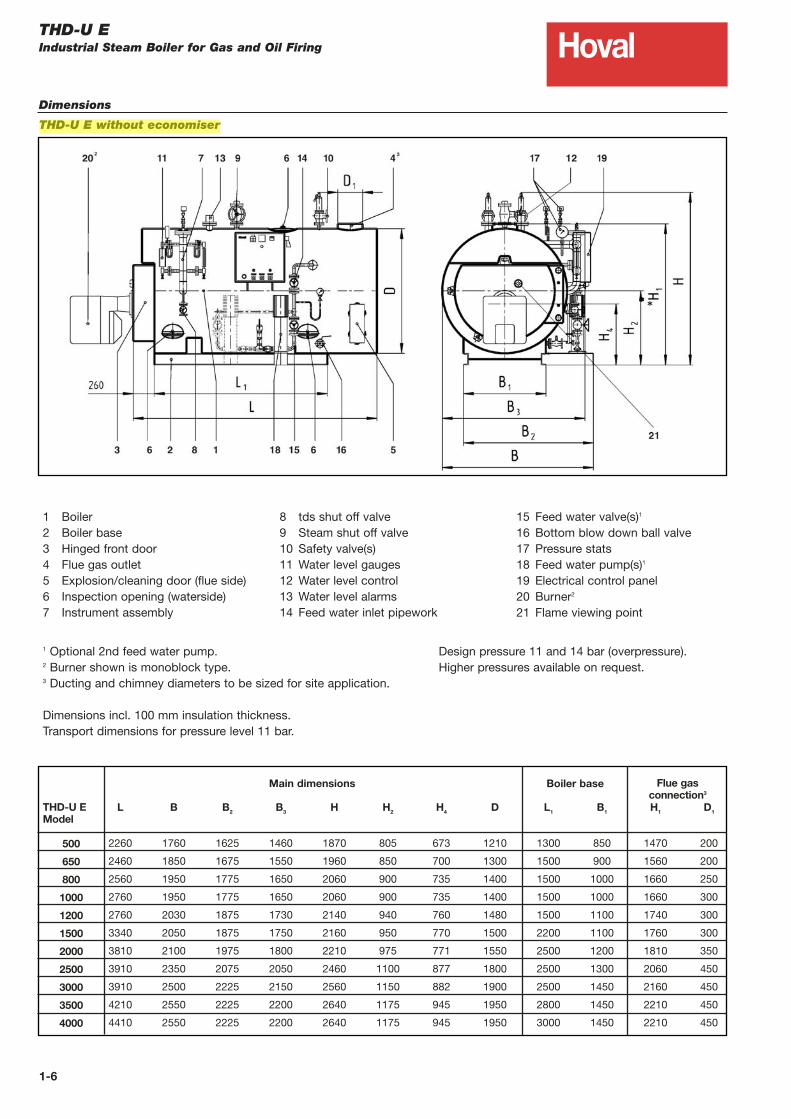
1-10 500 - 4000kg/hTHD-U E Industrial Steam Boiler for Gas and Oil Firing
Section 1
2-12 2000 - 20000kg/hTHSD-I E Industrial Steam Boiler for Gas and Oil Firing
Section 2

THD-U EIndustrial Steam Boiler for Oil and Gas Firing
Description
Hoval
Design, Quality & Construction
The Hoval high output steam boilers
are constructed from high quality steel
and are distinguished by their solid,
robust and flexible design. The Hoval
boiler combines ease of operation and
maintenance with optimal efficiency.
The boiler is designed with all
necessary inspection doors and is
constructed for gas or oil firing.
Construction and production is
according to EN12953, the Pressure
Equipment Directive 97/23/EG and CE
marked. An independent authorised
institution carries out quality approval
at our factory. The ISO 9001
certification and internal quality control
ensures excellent performance and
longevity of service. The client receives
an economical, environmentally friendly
compact unit, supplied ready for
installation.
THD-UE Steam Boiler
The THD-UE is a three-pass flame
tube/flue gas tube boiler with
reverse flame tube and an inner fully
water-cooled reversal chamber with
finned tube wall. The boiler consists of
a cylindrical shell, two endplates,
gusset stay supports, the reverse flame
tube with finned tube wall and single
pass dimpled flue gas tubes - which
increase the heat transfer (Hoval
patent), with low gas side resistance.
The boiler is completely electrically
welded and provided with all required
inspection openings.
The spacious flame tube with low
thermal heat release results in excellent
combustion and low emissions.
Large water content and steam space
provides steady state operation.
• Efficiency of up to 89% and up to
94.5% with economiser can be
achieved.
• Standard design
pressures of
11 and 14 barg are
available. Higher
pressures can be
manufactured on
request.
Thermal Insulation
The boiler is fully
insulated with
100 mm mineral wool
insulation. The casing is made of 1mm
thick stucco aluminum plate with
neatly trimmed connections and cut-
outs. The flue gas collector is also
thermally insulated.
Valves, Fittings & Sockets
• Water level regulation and water
level control
• Water level indicator (reflex type)
• Pressure switch for pressure
regulation and supervision
• Pressure gauge
• Main steam valve
• Safety valve(s)
• Feed pump, strainer and valves
• Manual tds
• Manual double valved
blowdown/drain
Boiler assembly
2 Heavy construction boiler
base supports
1 Instrument tube placed either on
the right (standard) or on the left
1 Flue gas collector with integrated
horizontal flue gas connection,
cleaning door and integrated
relief flap
1 Boiler door for burner mounting,
thermal insulated and designed
gas proof, placed on left and
right hinges for the flue
gas side cleaning of boiler
1 Internal feed water distribution pipe
1 Data plate
1 Low water mark
1 Internal steam dryer
1 Flue gas tube cleaning kit
Control Panel
The control panel is equipped with the
required controls and indicators for
control and supervision of the boiler
and burner. Control switches, indicator
lights and alarm signals are provided.
The control panel is supplied to match
the burner to be used.
Feed Water Quality
Boiler water quality has to be
respected. Detailed information can be
found in the appendix.
Also available
- Access ladder and platform
- Second feed water pump
- Second safety valve
- Modulating feedwater control
- Automatic tds blowdown
- Water sample cooler
- Automatic timed bottom blowdown
- Removable cladding sections
- Economiser
- Customised control panel
- Remote system monitoring and
controls
- Variable speed motor controls
- Hotwell and blowdown vessels
- Termed maintenance contracts
1-1
Hoval

HovalTHD-U EIndustrial Steam Boiler for Gas and Oil Firing
Technical data
THD-U E without and with economiser 500-1500
Technical data boiler without economiser (based on 10 barg working pressure)
Model 500 650 800 1000 1200 1500
Steam rating kg/h 500 650 800 1000 1200 1500
Operating output kW 326 423 521 651 781 977
Working pressure barg 10 10 10 10 10 10
Heating surface load (nominal capacity) kg/m2 66,3 61,4 64,0 64,7 61,5 61,5
Heating surface flue gas side (complete)* m2 7,54 10,58 12,50 15,45 19,50 24,40*For heating surface water side approximately +15%
Boiler efficiency minimum % 88,0 88,0 88,0 88,0 88,0 88,0
Pressure drop flue gas side mbar 3,5 3,6 3,9 4,0 4,4 4,5
Water content operating litres 600 910 960 970 1178 1386
Water content full litres 790 1076 1240 1332 1470 1965
Model 500 650 800 1000 1200 1500
Additional output with economiser kW 24 29 32 42 47 52
Boiler efficiency with economiser % 94,0 94,0 94,0 94,0 94,0 94,0
Pressure drop flue side including economiser mbar 6,5 6,6 6,9 7,0 7,4 7,5
Flue gas temperature after economiser °C 140 140 140 140 140 140
1-2
Technical data boiler with economiser (based on 10 barg working pressure)
Model 500 650 800 1000 1200 1500
Oil calorific value kJ/kg 42,700 42,700 42,700 42,700 42,700 42,700
Fuel consumption at full capacity kg/h 31 40 50 62 75 93
Wet flue gas volume at 2,7% O2 Nm3/h 433 550 677 846 1016 1269
Dry flue gas volume at 3% O2 Nm3/h 390 495 610 762 914 1143
Fuel heat input without economiser kW 377 479 591 736 882 1102
Fuel heat input with economiser kW 347 451 555 694 833 1041
Flue gas temperature °C 140 140 140 140 140 140
Technical data Diesel Oil (35 secs)
Model 500 650 800 1000 1200 1500
Natural gas calorific value kJ/Nm3 36,000 36,000 36,000 36,000 36,000 36,000
Fuel consumption at full capacity Nm3/h 35 45 56 69 83 104
Wet flue gas volume at 2,4% O2 Nm3/h 431 547 673 842 1010 1262
Dry flue gas volume at 3% O2 Nm3/h 368 467 575 719 863 1079
Fuel heat input without economiser kW 377 479 590 737 888 1110
Fuel heat input with economiser kW 347 451 555 694 833 1041
Flue gas temperature °C 140 140 140 140 140 140
Technical data Natural gas

HovalTHD-U EIndustrial Steam Boiler for Oil and Gas Firing
Technical data
THD-U E without and with economiser 2000-4000
Technical data boiler without economiser (based on 10 barg working pressure)
Model 2000 2500 3000 3500 4000
Steam rating kg/h 2000 2500 3000 3500 4000
Output kW 1303 1628 1953 2279 2605
Working pressure barg 10 10 10 10 10
Heating surface load (nominal capacity) kg/m2 63,0 58,2 57,6 58,8 58,9
Heating surface flue gas side (complete)* m2 31,74 42,93 52,10 59,50 67,90*For heating surface water side approximately +15%
Boiler efficiency minimum % 88,0 88,0 88,0 88,0 88,0
Pressure drop flue gas side mbar 5,2 5,3 5,8 6,1 6,8
Water content operating litres 2000 2575 2894 3240 3540
Water content full litres 2550 3500 3840 4270 4525
Model 2000 2500 3000 3500 4000
Additional output with economiser kW 69 82 105 134 165
Boiler efficiency with economiser % 94,0 94,0 94,0 94,0 94,0
Pressure drop flue side mbar 8,2 8,3 8,8 9,1 9,8
Flue gas temperature after economiser °C 140 140 140 140 140
Technical data boiler with economiser (based on 10 barg working pressure)
Model 2000 2500 3000 3500 4000
Oil EL calorific value kJ/kg 42,700 42,700 42,700 42,700 42,700
Fuel consumption at full capacity kg/h 124 155 186 217 249
Wet flue gas volume at 2,7% O2 Nm3/h 1693 2116 2539 2962 3385
Dry flue gas volume at 3% O2 Nm3/h 1524 1905 2286 2667 3048
Fuel heat input without economiser kW 1473 1846 2211 2580 2948
Fuel heat input with economiser kW 1388 1735 2082 2428 2776
Flue gas temperature °C 140 140 140 140 140
Technical data Diesel Oil (35 secs)
Model 2000 2500 3000 3500 4000
Natural gas calorific value kJ/Nm3 36,000 36,000 36,000 36,000 36,000
Fuel consumption at full capacity Nm3/h 138 184 208 243 278
Wet flue gas volume at 2,4% O2 Nm3/h 1683 2104 2552 2946 3366
Dry flue gas volume at 3% O2 Nm3/h 1483 1798 2157 2517 2876
Fuel heat input without economiser kW 1476 1843 2211 2580 2948
Fuel heat input with economiser kW 1388 1735 2082 2429 2776
Flue gas temperature °C 140 140 140 140 140
Technical data fuel Natural gas
1-3

HovalTHD-U EIndustrial Steam Boiler for Gas and Oil Firing
Technical data
THD-U E 500-4000
Dimensions and weights
1-4
Model 500 650 800 1000 1200 1500
Boiler length with insulation, without burner mm 2260 2460 2560 2760 2760 3340
Boiler length with Eco and insulation, mm 3300 3500 3550 3700 3700 4280
without burner
Boiler width with insulation, with pump mm 1760 1850 1950 1950 2030 2050
Boiler height with insulation, with fittings mm 1870 1960 2060 2060 2140 2160
Insulation thickness mm 100 100 100 100 100 100
Flue gas outlet diameter1 mm 200 200 250 300 300 300
Minimum draft tube length mm 350 350 350 350 350 350
Transport weight at 10 bar kg 2100 2300 2600 2900 3200 3400
Operating weight flooded at 10 bar kg 3100 3500 4200 4600 5000 5800
Manhole size mm 420x320 420x320 420x320 420x320 420x320 420x320
quantity no. 1 1 1 1 1 1
Inspection port size mm 80 80 80 80 80 80
quantity no. 2 2 2 2 2 2
Model 2000 2500 3000 3500 4000
Boiler length with insulation, with burner mm 3810 3910 3910 4210 4410
Boiler length with Eco and insulation, mm 4900 4900 4900 5200 5400
without burner
Boiler width with insulation, with pump mm 2100 2350 2500 2550 2550
Boiler height with insulation, with fittings mm 2210 2460 2560 2640 2640
Insulation thickness mm 100 100 100 100 100
Flue gas outlet diameter1 mm 350 450 450 450 450
Minimum draft tube length mm 350 350 350 350 350
Transport weight at 10 bar kg 4000 5000 6000 7000 8000
Operating weight flooded at 10 bar kg 6500 8900 10400 12000 13400
Manhole size mm 420x320 420x320 420x320 420x320 420x320
quantity no. 1 1 1 1 1
Inspection port size mm 80 80 80 80 80
quantity no. 2 2 2 2 2
1 Ducting and chimney diameters to be sized for site application.

Hoval
1-5
Flame Tube View
Fin
Tube
Reverse Flame Tube
THD-U EIndustrial Steam Boiler for Gas and Oil Firing
Design features
Three Pass Reverse Design
Fin Tube Wall
HovalTHD-U EIndustrial Steam Boiler for Gas and Oil Firing
Dimensions
THD-U E without economiser
1 Boiler
2 Boiler base
3 Hinged front door
4 Flue gas outlet
5 Explosion/cleaning door (flue side)
6 Inspection opening (waterside)
7 Instrument assembly
8 tds shut off valve
9 Steam shut off valve
10 Safety valve(s)
11 Water level gauges
12 Water level control
13 Water level alarms
14 Feed water inlet pipework
15 Feed water valve(s)1
16 Bottom blow down ball valve
17 Pressure stats
18 Feed water pump(s)1
19 Electrical control panel
20 Burner2
21 Flame viewing point
L
2260
2460
2560
2760
2760
3340
3810
3910
3910
4210
4410
B
1760
1850
1950
1950
2030
2050
2100
2350
2500
2550
2550
B2
1625
1675
1775
1775
1875
1875
1975
2075
2225
2225
2225
B3
1460
1550
1650
1650
1730
1750
1800
2050
2150
2200
2200
H
1870
1960
2060
2060
2140
2160
2210
2460
2560
2640
2640
H2
805
850
900
900
940
950
975
1100
1150
1175
1175
H4
673
700
735
735
760
770
771
877
882
945
945
D
1210
1300
1400
1400
1480
1500
1550
1800
1900
1950
1950
L1
1300
1500
1500
1500
1500
2200
2500
2500
2500
2800
3000
B1
850
900
1000
1000
1100
1100
1200
1300
1450
1450
1450
H1
1470
1560
1660
1660
1740
1760
1810
2060
2160
2210
2210
D1
200
200
250
300
300
300
350
450
450
450
450
THD-U EModel
500
650
800
1000
1200
1500
2000
2500
3000
3500
4000
Main dimensions Boiler base Flue gasconnection3
1 Optional 2nd feed water pump.2 Burner shown is monoblock type.3 Ducting and chimney diameters to be sized for site application.
Dimensions incl. 100 mm insulation thickness.
Transport dimensions for pressure level 11 bar.
Design pressure 11 and 14 bar (overpressure).
Higher pressures available on request.
1-6

Hoval
1-7
THD-U EIndustrial Steam Boiler for Gas and Oil Firing
Technical data
THD-U E with economiser
1 Boiler
2 Boiler base
3 Hinged front door
4 Flue gas outlet
5 Explosion/cleaning door (flue side)
6 Inspection opening (waterside)
7 Instrument assembly
8 tds shut off valve
9 Steam shut off valve
10 Safety valve(s)
11 Water level gauges
12 Water level control
13 Water level alarms
14 Feed water inlet pipework
15 Feed water valve(s)1
16 Bottom blow down ball valve
17 Pressure stats
18 Feed water pump(s)1
19 Electrical control panel
20 Burner2
21 Flame viewing point
22 Economiser4
L
3300
3500
3550
3700
3700
4280
4900
4900
4900
5200
5400
B
1760
1850
1950
1950
2030
2050
2100
2350
2500
2550
2550
B2
1625
1675
1775
1775
1875
1875
1975
2075
2225
2225
2225
B3
1460
1550
1650
1650
1730
1750
1800
2050
2150
2200
2200
H
1870
1960
2060
2060
2140
2160
2210
2460
2560
2640
2640
H1
1470
1560
1660
1660
1740
1760
1810
2060
2160
2210
2210
H2
805
850
900
900
940
950
975
1100
1150
1175
1175
H4
673
700
735
735
760
770
771
877
882
945
945
D
1210
1300
1400
1400
1480
1500
1550
1800
1900
1950
1950
L1
1300
1500
1500
1500
1500
2200
2500
2500
2500
2800
3000
B1
850
900
1000
1000
1100
1100
1200
1300
1450
1450
1450
H3
805
850
900
900
940
950
975
1100
1150
1175
1175
D1
200
200
250
300
300
300
350
450
450
450
450
THD-U EModel
500
650
800
1000
1200
1500
2000
2500
3000
3500
4000
Main dimensions Boiler base Flue gasconnection3
1 Optional 2nd feed water pump.2 Burner shown is monoblock type.3 Ducting and chimney diameters to be sized for site application.4 Economiser can be positioned vertically.
Dimensions incl. 100 mm insulation thickness.
Transport dimensions for pressure level 10 bar.
*Add 100mm to H1 for crane hooks.
Design pressure 11 and 14 bar (overpressure).
Higher pressures available on request.

Hoval
1-8
To facilitate installation andmaintenance the stated clearancesshould be met. Drawing indicates righthand (standard) hinged door.
Minimal space refers to boiler.Depending on equipment (accessories)the minimal space needs to bereviewed according to local codes.
Positioning
- No air pollution throughhalogenated hydrocarbon(contained e.g. sprays, paints, solvents and cleaners)
- No large amounts of dust- No high atmospheric humidity- Frost-resistant and well ventilated- Boiler to be installed and
positioned in a weatherproof, non-hazardous and safe classified area.
Otherwise damage to the installationmay occur.
The boiler may only be installed inrooms where air pollution throughhalogenated hydrocarbon can occur ifsufficient measures are taken ensuringthe supply of unpolluted combustionair.
Boiler room dimensions can bereduced by the fitting of a shutter dooror knockout panel.
Model
THD-U E a (mm)
500
1850
650
2050
800
2050
1000
2050
1200
2050
1500
2750
2000
3050
2500
3050
Model
THD-U E a (mm)
3000
3050
3500
3350
4000
3550
*300mm+ burner overall length (consider pivoting range/pivoting side)**Consider control panel, pump(s) assembly***Flame tube length for tube witdrawal and cleaning
THD-U EIndustrial Steam Boiler for Gas and Oil Firing
Technical data
Installation
a ***
* 1200Minimum
** 1200Minimum
500 Minimum
500 Minimum

Hoval
1-9
THD-U EIndustrial Steam Boiler for Gas and Oil Firing
Engineering
Rules and regulations
The following rules and regulations
have to be respected:
- Hoval technical information and
installation guide
- Fire protection regulations
- National regulations concerning
permission, installation and operation of
boiler appliances. Boiler appliances
have to be installed according to
national laws and regulations and
accessory requirements.
- Besides the national and local
regulations the project specific
circumstances of the boiler supplier
have to be considered for every
application.
Water treatment/water quality
- The quality of the boiler water has to be
guaranteed according to Hoval technical
information and national guidelines.
- Hoval boilers may only be operated with
treated water. The national regulations
for the treatment of water apply for the
values to be maintained.
- Required water quality: see page 1-10.
- The water quality has to be checked
daily.
Planning, operation and
maintenance
- The heating of the feed water and the
degassing takes place in the feed water
tank (hot well).
- To increase the efficiency, especially for
natural gas operation, an economiser
can be added to pre-heat the feed
water.
- Pumps (especially horizontal rotary
pumps and warm water/condensate
pumps, NPSH pumps) need to be
installed with the necessary flow and
return pipework according to
requirements. The installation has to be
completely free of tension (anti-
vibration proof).
- Feedwater tank height must satisfy the
feed pump NPSH requirement.
- National and local rules and regulations
have to be considered for the fuel
supply. Fuel filters are highly
recommended
- The operation and water analysis data
is to be recorded daily in the operation
booklet.
- Safety valve, condensate and blowdown
connections must discharge to a safe
place.
- Filters and strainers have to be cleaned
periodically, especially if installed in
front of control devices.
- The drain of the tds, blow down,
drainage, etc has to be safely
discharged into a blowdown vessel.
- All heating components and pipework
are to be insulated in order to reduce
radiation losses.
Combustion air
- The supply of combustion air must be
guaranteed for a safe and economic
operation. There must be no possibility
of the air supply being shut off.
- Ventilation of the boiler house has to
also be provided.
- In the installation room no negative
pressure larger than 3 N/m2 is allowed.
To adhere to this demand, plan a free
area for the air supply opening of at
least 200 cm2, plus 2 cm2 per KW
output. The aspect ratio for rectangular
openings should not be more than 1.5 :1.
If the opening is louvered ensure
the free area is sufficient. National laws
have to be respected.
- Boiler houses have to be fitted with
relevant fresh air supply openings or
ducted system.
- Gas boilers are not to be installed in
rooms where halogen compounds occur
which can enter the combustion air.
Noise level reduction
The following measures for noise level
reduction are possible:
- Solid construction of boiler room
walls, ceiling and floor, installation
of silencer in fresh air supply, noise
insulation for support and bracket
of pipes.
- Installation of acoustic shroud for
the burner.
- A substantial part of the sound caused
in the combustion chamber and in the
top heating surfaces is radiated from
the flue outlet as sound transmitted by
air. In addition to this, resonance
features, depending on chimney
dimensioning and inlet, may occur
which are triggered by the oscillation of
the combustion process. These sounds
can be reduced by burner-lateral
measures, e.g. changes of flame
geometry, atomisation characteristics or
fuel throughput.
- Flue gas attenuators cause a substantial
sound level reduction. These should
usually be tuned at low frequencies of
60 - 250 Hz. Flue gas attenuators
function according to the principle of
sound absorption. The kinetic energy of
the exhaust gases is reduced by friction
requiring an increase in chimney draft in
the flue system. This has to be
considered for burner sizing. The
connection piece from the boiler to the
flue gas sound absorber has to be
gastight.
- The necessary space requirement of
approximately 1 m for the later
installation of a flue gas attenuator
should already be included when
planning.
Chimney/flue gas system
- A properly designed chimney/flue
arrangement must be provided to
match each particular application.
- To achieve a smooth discharge of the
exhaust gases from the boiler into the
chimney, the flue connection is
recommended to enter the chimney at
approximately 30-45°.
- From a length of greater than 1 m
thermal insulation is necessary.
- Adequate provision should be made to
drain off condensate from the base of
the chimney ensuring condensate does
not run back into the boiler smokebox.

Hoval
1-10
THD-U EIndustrial Steam Boiler for Gas and Oil Firing
Boiler and feed water specifications for steam boiler plants
Feed water specifications for natural circulating boilers
Boiler water specifications for natural circulating boilers
Working pressure bar <1 >1 < 22 >22 < 68
Properties colourless, clear, free from suspended matter and foam
pH-value at 25°C > 9 > 9 >9
Sum of alkaline earth elements (Ca + Mg)1 mmol/l < 0,02 < 0,02 < 0,01
°dH < 0,112 < 0,112 < 0,056
Conductivity at 25°C µS/cm see guidelines for boiler water specifications only
Oxygen (O2) mg/l < 0,1 < 0,02 < 0,02
Carbon dioxide (CO2) dissolved mg/l < 25 < 25 < 25
Iron (Fe), total mg/l - < 0,05 < 0,03
Copper (Cu), total mg/l - < 0,01 0,005
Silicate acid (SiO2) mg/l see guidelines for boiler water only
Consumption of Potassium permanganate mg/l < 10 < 10 < 10
Oil, fat mg/l < 3 < 1 < 1
1 Noted in the past at °dH, changing factor: 1 mmol/l = 5,6 °dH (German hardness).
It is not necessary to make continuous control of the following parameters: Conductivity, Oxygen (O2), Carbon dioxide (CO2)
dissolved, Iron (Fe), total, Copper (Cu), total, Silicate (SiO2), Consumption of Potassium permanganate, Oil, fat.
Working pressure bar <1 >1 < 22 >22 < 44
Properties colourless, clear, free from suspended matter and foam
pH-value at 25°C 10,5-12 10,5-12 10-11,8
Sum of alkaline earth elements (Ca + Mg)2 mmol/l < 0,02 < 0,02 < 0,01
°dH < 0,112 < 0,112 < 0,056
Conductivity at 25°C µS/cm < 5000* < 5000* < 2000*
Acid capacity KS 8,23 (p-value) mmol/l 1-12 1-12 0,5-6
Carbon dioxide (CO2) dissolved mg/l < 25 < 25 < 25
Iron (Fe), total mg/l - < 0,05 < 0,03
Silicate acid (SiO2) mg/l < 150 < 100 < 50
Phosphate (P2O4)4 mg/l 10-20 5-10 5-10
Sodium sulphate (Na2SO3)4 mg/l 5-10 5-10 3-5
(Polyamide)5 mg/l (3-5) (3-5) --
1 Take care to maintain the allowed value of acid capacity - at this point the allowed conductivity has to be lower on many
plants; for water level electrodes minimum conductivity > 5 µS/cm2 Noted in the past at °dH, changing factor: 1 mmol/l = 5,6 °dH (German hardness)3 Noted in the past as p-value, changing factor: KS 8,2 = 1 according p-value = 14 Measurements only necessary if dosing chemicals are used which contains these values5 It is recommended to use Amine (film producing) only instead of other dosing chemicals for boilers which have a small
heating load and up to maximum 16 bar working pressure. Because of the danger of foam production overdosing is not
permitted!
Boiler water quality to comply with BS2486.It is not necessary to make continuous control of the following parameters: Silicate (SiO2)
Important note: Hoval recommend that a water treatment specialist is employed to advise on each application and to carry
out routine monitoring of the feed and boiler water to ensure it remains within specification.

Hoval
1-11
Industrial steam and hot water boilers
Boiler plant total supply package
Hoval can design and supply all components for the boiler plant room including in-house manufacture of the
Steam or Hot Water Boiler, Hotwells (Feedwater Tanks), Blowdown Vessels, Deaerators and Economisers
where appropriate.

HovalIndustrial steam and hot water boilers
Design of steam boiler plant
1-12
STE
AM
BO
ILE
RE
CO
NO
MIS
ER
HO
TW
ELL
WATE
R T
RE
ATM
EN
TC
ON
DE
NSAT
E S
TAT
ION

THSD-I EIndustrial Steam Boiler for Gas and Oil Firing
Description
Hoval
Design, Quality & Construction
The Hoval high output steam boilers
are constructed from high quality steel
and are distinguished by their solid,
robust and flexible design. The Hoval
boiler combines ease of operation and
maintenance with optimal efficiency.
The boiler is designed with all
necessary inspection doors and is
constructed for gas or oil firing.
Construction and production is
according to EN12593, the Pressure
Equipment Directive 97/23/EG and CE
marked. An independent authorised
institution carries out quality approval
at our factory. The ISO 9001
certification and internal quality control
ensures excellent performance and
longevity of service. The client receives
an economical, environmentally friendly
compact unit, supplied ready for
installation
THSD-IE Steam Boiler
The THSD-IE is a three-pass flame
tube/flue gas tube boiler with
an inner fully water-cooled reversal
chamber with finned tube wall. The
boiler consists of a cylindrical shell, two
endplates, gusset stay supports, flame
tube, gas reversal chamber with
water cooled finned tube wall and two
tube bank gas passes with low gas
side resistance. The boiler is
completely electrically welded and
provided with all required inspection
openings.
The spacious flame tube with low
thermal heat release results in excellent
combustion and low emissions.
Large water content and steam space
provides steady state operation.
• Efficiency of up to 91% and up to
95% with economiser can be
achieved.
• Standard design
pressures of
10,13,16 and 20 barg
are available. Higher
pressures can be
manufactured on
request.
Thermal Insulation
The boiler is fully
insulated with
120 mm mineral wool
insulation. The casing is made of 1mm
thick stucco aluminum plate with neatly
trimmed connections and cut-outs. The
flue gas collector is also thermally
insulated.
Valves, Fittings & Sockets
• Water level regulation and water
level control
• Water level indicator (reflex type)
• Pressure switch for pressure
regulation and supervision
• Pressure gauge
• Main steam valve
• Safety valve(s)
• Feed pump, strainer and valves
• Manual tds
• Manual-double valve
blowdown/drain
Boiler assembly
2 Heavy construction boiler
base supports
1 Instrument tube placed either on
the right (standard) or on the left
1 Flue gas collector with integrated
horizontal flue gas connection,
cleaning door and integrated
relief flap
1 Boiler door for burner mounting,
thermal insulated and designed
gas proof, placed on left and
right hinges for the flue
gas side cleaning of boiler
1 Internal feed water distribution pipe
1 Data plate
1 Low water mark
1 Internal steam dryer
1 Flue gas tube cleaning kit
Control Panel
The control panel is equipped with the
required controls and indicators for
control and supervision of the boiler
and burner. Control switches, indicator
lights and alarm signals are provided.
The control panel is supplied to match
the burner to be used.
Feed Water Quality
Boiler water quality has to be
respected. Detailed information can be
found in the appendix.
Also available
- Access ladder and platform
- Second feed water pump
- Second safety valve
- Modulating feedwater control
- Automatic tds blowdown
- Water sample cooler
- Automatic timed bottom blowdown
- Removable cladding sections
- Economiser
- Customised control panel
- Remote system monitoring and
controls
- Variable speed motor controls
- Hotwell and blowdown vessels
- Termed maintenance contracts
2-1

HovalTHSD-I EIndustrial Steam Boiler for Gas and Oil Firing
Technical data
THSD-I E 2000-8000
Technical data without economiser
Model 2000 2500 3000 4000 5000 6000 8000
Steam output kg/h 2000 2500 3000 4000 5000 6000 8000Operating output at 10 barg kW 1304 1630 1956 2608 3260 3912 5216
at 13 barg kW 1308 1635 1963 2617 3271 3925 5234at 16 barg kW 1311 1639 1967 2623 3278 3934 5246
Boiler efficiency Natural gas at 10 barg % 89,8 90,0 89,7 89,9 90,2 90,4 89,7at 13 barg % 89,3 89,5 89,2 89,4 89,7 90,0 89,2at 16 barg % 89,0 89,1 89,9 89,0 89,3 89,5 89,0
Boiler efficiency at 10 barg % 90,2 90,1 89,8 89,9 90,2 90,4 89,7Diesel Oil (35 secs) at 13 barg % 89,7 89,6 89,3 89,4 89,7 90,0 89,2
at 16 barg % 89,3 89,2 89,0 89,0 89,3 89,5 89,0
Flue gas resistance mbar 9,0 9,0 10,0 10,0 10,0 10,0 10,0
Model 2000 2500 3000 4000 5000 6000 8000
Additional operating output at 10 barg kW 62 79 102 131 154 175 272with economiser at 13 barg kW 68 88 116 144 171 194 299
at 16 barg kW 74 95 120 156 186 213 315
Boiler efficiency with economiser % 94,4 94,4 94,4 94,4 94,4 94,4 94,4Flue gas resistance of economiser mbar 2.5 2.5 2.5 2.5 2.5 2.5 2.5
Flue gas temperature after economiser °C 140 140 140 140 140 140 140
Technical data with integral economiser, fuel natural gas and low sulphur fuel oil
2-2
Model 2000 2500 3000 4000 5000 6000 8000
Natural gas calorific value kJ/Nm3 36000 36000 36000 36000 36000 36000 36000
Fuel consumption at at 10 barg Nm3/h 145,3 181,1 220,7 290,3 361,7 432,9 581,9full capacity at 13 barg Nm3/h 146,7 182,7 222,7 292,9 364,9 436,5 587,1
at 16 barg Nm3/h 147,7 184,0 224,2 294,9 367,5 439,8 583,6
Flue gas volume, at 10 barg Nm3/h 1688 2018 2458 3234 4030 4822 6482excess air @10% at 13 barg Nm3/h 1701 2036 2481 3263 4066 4863 6540
at 16 barg Nm3/h 1414 2050 2498 3285 4094 4899 6501
Fuel heat input at 10 barg kW 1453 1811 2181 2902 3614 4327 5815at 13 barg kW 1465 1826 2201 2928 3647 4361 5868at 16 barg kW 1476 1839 2215 2948 3671 4396 5901
Technical data Natural Gas
Model 2000 2500 3000 4000 5000 6000 8000
Diesel Oil calorific value kJ/kg 42700 42700 42700 42700 42700 42700 42700
Fuel consumption at at 10 barg kg/h 121,9 152,6 183,8 244,6 304,9 364,9 490,3full capacity at 13 barg kg/h 123,0 154,0 185,4 246,8 307,6 368,0 494,7
at 16 barg kg/h 123,9 155,1 186,7 284,5 309,8 370,8 491,8
Flue gas volume, at 10 barg Nm3/h 1647 2061 2482 3304 4117 4928 6621excess air @12% at 13 barg Nm3/h 1661 2080 2504 3333 4154 4970 6680
at 16 barg Nm3/h 1673 2094 2522 3365 4183 5007 6641
Fuel heat input at 10 barg kW 1446 1810 2179 2900 3614 4327 5815at 13 barg kW 1458 1825 2199 2926 3647 4361 5868at 16 barg kW 1468 1838 2213 2947 3671 4396 5894
Technical data Diesel Oil (35 secs)

HovalTHSD-I EIndustrial Steam Boiler for Gas and Oil Firing
Technical data
THSD-I E 10000-20000
Technical data without economiser
Model 10000 12000 14000 16000 18000 20000
Steam rating kg/h 10000 12000 14000 16000 18000 20000Operating output at 10 barg kW 6520 7824 9128 10432 11736 13040
at 13 barg kW 6542 7850 9159 10467 11776 13084at 16 barg kW 6557 7868 9180 10491 11802 13114
Boiler efficiency Natural gas at 10 barg % 89,9 89,8 89,8 89,9 89,6 89,9at 13 barg % 89,4 89,5 89,4 89,4 89,2 89,4at 16 barg % 89,2 89,1 89,0 89,0 89,0 89,0
Boiler efficiency at 10 barg % 89,9 89,89 89,9 89,8 89,7 89,9Diesel Oil (35 secs) at 13 barg % 89,4 89,5 89,5 89,5 89,2 89,4
at 16 barg % 89,1 89,0 89,0 89,0 89,0 89,0
Flue gas resistance mbar 11,0 10,0 10,0 10,0 11,0 11,0
Model 10000 12000 14000 16000 18000 20000
Additional operating output at 10 barg kW 326 399 465 522 622 652with economiser at 13 barg kW 366 432 513 586 686 732
at 16 barg kW 382 464 557 637 716 796
Boiler efficiency with economiser % 94,4 94,4 94,4 94,4 94,4 94,4Flue gas resistance of economiser mbar 2,5 2,5 2,5 3,0 3,0 3,0
Flue gas temperature after economiser °C 140 140 140 140 140 140
Technical data with integral economiser, fuel natural gas and low sulphur fuel oil
2-3
Model 10000 12000 14000 16000 18000 20000
Natural gas calorific value kJ/Nm3 36000 36000 36000 36000 36000 36000
Fuel consumption related at 10 barg Nm3/h 725,7 871,4 1016,7 1162,1 1310,0 1451,5at 13 barg Nm3/h 732,2 877,4 1024,6 1171,1 1320,1 1464,5at 16 barg Nm3/h 728,0 883,6 1031,7 1179,3 1329,4 1474,7
Flue gas volume, at 10 barg Nm3/h 8084 9707 11327 12946 14594 16170excess air @10% at 13 barg Nm3/h 8156 9774 11414 13046 14706 16315
at 16 barg Nm3/h 8110 9843 11494 13137 14809 16429
Fuel heat input at 10 barg kW 7253 8713 10165 11604 13098 14505at 13 barg kW 7318 8771 10245 11708 13020 14635at 16 barg kW 7351 8831 10315 11788 13291 14735
Technical data Natural Gas
Model 10000 12000 14000 16000 18000 20000
Diesel Oil calorific value kJ/kg 42700 42700 42700 42700 42700 42700
Fuel consumption related at 10 barg kg/h 611,5 734,3 856,8 979,3 1103,8 1223,2at 13 barg kg/h 617,0 739,5 863,5 987,0 1112,4 1234,2at 16 barg kg/h 613,6 744,7 869,7 994,0 1120,3 1245,9
Flue gas volume, at 10 barg Nm3/h 8259 9916 11571 13226 14907 16520excess air @12% at 13 barg Nm3/h 8333 9987 11662 13329 15023 16667
at 16 barg Nm3/h 8287 10057 11745 13424 15129 16756
Fuel heat input at 10 barg kW 7253 8703 10154 11617 13084 14505at 13 barg kW 7318 8771 10234 11695 13202 14635at 16 barg kW 7359 8860 10338 11788 13291 14735
Technical data Diesel Oil (35 secs)
HovalTHSD-I EIndustrial Steam Boiler for Gas and Oil Firing
Technical data
THSD-I E 2000-8000
Dimensions and weights
2-4
Model 2000 2500 3000 4000 5000 6000 8000
Boiler length with insulation, without burner,
without economiser mm 3750 3950 4150 4500 4950 5150 5650
Boiler length with economiser,
without insulation, without burner mm 4700 4900 5100 5450 5900 6100 6600
Boiler width with insulation, with pump mm 2450 2550 2600 2700 2800 2900 3100
Boiler height with insulation, with fittings mm 2700 2800 2850 3075 3250 3400 3650
Insulation thickness mm 120 120 120 120 120 120 120
Flue gas outlet diameter (ducting, and mm 350 450 450 550 550 650 650
chimney diameters to be sized for site application
Heating surface flue gas side (complete)* m2 47,4 57,3 65,9 88,4 108,3 129,2 169,7
*For heating surface water side approximately +15%
Water content operating litres 2750 4350 4850 5850 7200 8200 10000
flooded litres 4600 5450 6000 7250 9000 10300 12500
Transport weight without at 10 barg kg 5000 6000 7000 8000 9500 11000 14500
burner and without Economiser at 13 barg kg 5500 6500 7500 8500 10500 12000 15500
including accessories at 16 barg kg 6000 7000 8000 9500 11500 13500 16500
Manhole (size) mm 420 x 420 x 420 x 420 x 420 x 420 x 420 x
320 320 320 320 320 320 320
(quantity) 1 1 1 1 1 1 1
Inspection opening (size) mm 220 x 220 x 220 x 220 x 220 x 220 x 220 x
150 150 150 150 150 150 150
(quantity) 2 2 2 2 2 2 2
Design features
Three Pass Conventional Design
Flame Tube

HovalTHSD-I EIndustrial Steam Boiler for Gas and Oil Firing
Technical data
THSD-I E 10000-20000
Dimensions and weights
Model 10000 12000 14000 16000 18000 20000
Boiler length with insulation, without burner,
without economiser mm 6150 6550 6850 7150 7350 7850
Boiler length with economiser,
without insulation, without burner mm 7050 7450 7750 8050 8250 8750
Boiler width with insulation, with pump mm 3300 3400 3600 3700 3800 3900
Boiler height with insulation, with fittings mm 3925 4125 4350 4425 4625 4725
Insulation thickness mm 120 120 120 120 120 120
Flue gas outlet diameter mm 800 850 950 1000 1000 1000
chimney diameters to be sized for site application
Heating surface flue gas side (complete)* m2 211,8 284,5 324,9 381,3 410,7 467,6
*For heating surface water side approximately +15%
Water content operating litres 14200 15900 17600 20000 23000 24250
flooded litres 18000 20350 22700 25000 29200 31400
Transport weight without at 10 barg kg 17500 21500 25000 28000 30000 33000
burner and without Economiser at 13 barg kg 18500 21500 26000 29000 31000 35000
including accessories at 16 barg kg 19500 24000 28000 31000 35000 39000
Manhole (size) mm 420 x 420 x 420 x 420 x 420 x 420 x
320 320 320 320 320 320
(quantity) 1 1 1 1 1 1
Inspection opening (size) mm 220 x 220 x 220 x 220 x 220 x 220 x
150 150 150 150 150 150
(quantity) 2 2 2 2 2 2
2-5
Construction View
Mounting of the Fin
tube wall
Second pass
Third pass

Hoval
Model 2000 2500 3000 4000 5000 6000 8000
1 Flue gas tube cleaning equipment YES YES YES YES YES YES YES
1 Main steam valve 10 barg DN80 DN80 DN100 DN100 DN100 DN125 DN15013 barg DN65 DN80 DN80 DN100 DN100 DN100 DN12516 barg DN65 DN65 DN80 DN80 DN100 DN100 DN125
1 Vent valve DN25 DN25 DN25 DN25 DN25 DN25 DN25
2 Safety valves* 10 barg DN25/40 DN25/40 DN32/50 DN32/50 DN32/50 DN40/65 DN40/6513 barg DN25/40 DN25/40 DN25/40 DN32/50 DN32/50 DN32/50 DN40/6516 barg DN25/40 DN25/40 DN25/40 DN25/40 DN32/50 DN32/50 DN32/50
2 Isolation valves DN20 DN20 DN20 DN20 DN20 DN20 DN20
2 Reflection indicators fixing centre (mm) 420 420 420 420 420 420 420
1 Blow down sight glass drain (screwed) 1/2" 1/2" 1/2" 1/2" 1/2" 1/2" 1/2"
1 Desalting shut off valve DN15 DN15 DN15 DN15 DN15 DN15 DN15
1 Blow down shut off valve DN40 DN40 DN40 DN40 DN40 DN40 DN40
1 Blow down ball valve DN40 DN40 DN40 DN40 DN40 DN40 DN40
1 Pressure gauge with three-way valve (screwed) 1/2" 1/2" 1/2" 1/2" 1/2" 1/2" 1/2"
Water level control type
1 Feed water valve DN25 DN32 DN32 DN32 DN40 DN40 DN50
1 Feed water non-return valve/anti syphon valve DN25 DN32 DN32 DN32 DN40 DN40 DN50
1 Strainer pump (suction side) DN40 DN50 DN50 DN50 DN65 DN65 DN80
1 Ball valve pump (suction side) DN40 DN50 DN50 DN50 DN65 DN65 DN80
1 Pressure gauge (pump) withshut off valve (screwed) 1/4" 1/4" 1/4" 1/4" 1/4" 1/4" 1/4"
1 Feed water pump 10 barg CR CR CR CR CR CR CRMotor rating kW 2.2 2.2 3.0 4.0 4.0 5.5 5.5
1 Feed water pump 13 barg CR CR CR CR CR CR CRMotor rating kW 2.2 3.0 4.0 4.0 4.0 7.5 7.5
1 Feed water pump 16 barg CR CR CR CR CR CR CRMotor rating kW 3.0 4.0 4.0 5.5 7.5 7.5 11.0
*Safety valve number and size to be advised at contract stage subject to set pressure requirement.
THSD-I EIndustrial Steam Boiler for Gas and Oil Firing
Technical data
THSD-I E 2000-8000
Fittings
2-6
ON/OFF

HovalTHSD-I EIndustrial Steam Boiler for Gas and Oil Firing
Technical data
THSD-I E 10000-20000
Fittings
Model 10000 12000 14000 16000 18000 20000
1 Flue gas tube cleaning equipment YES YES YES YES YES YES
1 Main steam valve 10 barg DN150 DN200 DN200 DN200 DN200 DN250
13 barg DN150 DN150 DN200 DN200 DN200 DN200
16 barg DN125 DN150 DN150 DN150 DN200 DN200
1 Vent valve DN25 DN25 DN25 DN25 DN25 DN25
2 Safety valve* 10 barg DN50/80 DN50/80 DN65/100 DN65/100 DN65/100 DN65/100
13 barg DN40/65 DN50/80 DN50/80 DN65/100 DN65/100 DN65/100
16 barg DN40/65 DN40/65 DN50/80 DN50/80 DN50/80 DN65/100
2 Isolation valve DN20 DN20 DN20 DN20 DN20 DN20
2 Reflection indicators fixing centre (mm) M=420 M=420 M=420 M=420 M=420 M=420
1 Blow down sight glass drain (screwed) 1/2" 1/2" 1/2" 1/2" 1/2" 1/2"
1 tds shut off valve DN15 DN15 DN15 DN15 DN15 DN15
1 Blow down shut off valve DN40 DN40 DN40 DN40 DN40 DN40
1 Blow down ball valve DN40 DN40 DN40 DN40 DN40 DN40
1 Pressure gauge with three-way valve 1/2" 1/2" 1/2" 1/2" 1/2" 1/2"
Water level control type
1 Feed water valve DN50 DN50 DN65 DN80 DN80 DN80
1 Feed water non-return valve/anti syphon valve DN50 DN50 DN65 DN80 DN80 DN80
1 Strainer pump (suction side) DN80 DN80 DN100 DN125 DN125 DN125
1 Ball valve pump (suction side) DN 80 DN 80 DN100 DN125 DN125 DN125
1 Pressure gauge (pump) with shut off valve 1/4" 1/4" 1/4" 1/4" 1/4" 1/4"
1 Feed water pump 10 barg CR CR CR CR CR CR
Motor rating kW 11.0 11.0 11.0 11.0 15.0 15.0
1 Feed water pump 13 barg CR CR CR CR CR CR
Motor rating kW 11.0 11.0 15.0 15.0 18.5 18.5
1 Feed water pump 16 barg CR CR CR CR CR CR
Motor rating kW 15.0 15.0 18.5 18.5 18.5 22.0
*Safety valve number and size to be advised at contract stage subject to set pressure requirement.
2-7
MODULATING

HovalTHSD-I EIndustrial Steam Boiler for Gas and Oil Firing
Technical data
THSD-I E without economiser
1 Boiler
2 Boiler base
3 Front reversal chamber
Hinged front door
4 Flue gas outlet
5 Explosion/cleaning door (flue side)
6 Inspection openings (water side)
7 Instrument assembly
8 tds shut off valve
9 Steam shut off valve
10 Safety valve(s)
11 Water level gauges
12 Water level control
13 Water level alarms
14 Feed water inlet
15 Feed water valve(s)
16 Bottom blow down ball valve
17 Pressure stats
18 Feed water pump(s)
19 Electrical control panel
20 Burner5
21 Vent valve
22 Condensate drainage
23 Flame viewing port
L
3750
3950
4150
4500
4950
5150
5650
6150
6550
6850
7150
7350
7850
B
2450
2550
2600
2700
2800
2900
3100
3300
3400
3600
3700
3800
3900
H
2700
2800
2850
3075
3250
3400
3650
3925
4125
4350
4425
4625
4725
H1
2250
2350
2400
2550
2650
2800
2925
3200
3300
3500
3600
3700
3800
H2
1175
1225
1250
1350
1400
1450
1550
1700
1750
1850
1900
1950
2000
D
1990
2090
2140
2240
2340
2440
2640
2840
2940
3140
3240
3340
3440
L3
300
300
300
300
300
300
300
350
350
350
350
350
350
L4
700
700
700
700
700
700
700
850
850
850
850
850
850
L1
2300
2500
2700
3000
3400
3600
4100
4500
5000
5000
5500
5500
6000
L2
400
400
400
400
400
400
400
475
475
475
475
475
475
B1
1175
1225
1250
1350
1400
1450
1550
1700
1750
1850
1900
1950
2000
B2
160
160
160
160
160
160
160
200
200
200
200
200
200
H3
1750
1825
1850
1950
2000
2100
2200
2350
2400
2500
2550
2650
2700
D1
350
450
450
550
550
650
650
800
850
950
1000
1000
1000
THSD-I EModel
2000
2500
3000
4000
5000
6000
8000
10000
12000
14000
16000
18000
20000
Main dimensions Boiler base Flue gasconnection6
1 up to THSD-I E (4000) 100mm less2 up to THSD-I E (4000) 200mm less3 up to THSD-I E (4000) 100mm less, from THSD-I E (12000) 100mm more4 up to THSD-I E (4000) 200mm less, from THSD-I E (12000) 100mm more5 Burner shown is monobloc type. Width/height may alter with fabricated
wind box type burner.6 Ducting and chimney diameters to be sized for site application
Pos. 14 up to THSD-I E (4000) 400mm less
Dimensions incl. 120 mm insulation thickness
Design pressure 10, 13 and 16 bar
(overpressure)
Other models available for different working
pressures.
Transport dimensions for pressure level 10 bar.
Add 100mm to H1 for crane hooks.
2-8

HovalTHSD-I EIndustrial Steam Boiler for Gas and Oil Firing
Technical data
THSD-I E with economiser - subject to local site alterations
1 Boiler
2 Boiler base
3 Front reversal chamber
Hinged front door
4 Flue gas outlet
5 Explosion/cleaning door (flue side)
6 Inspection openings (water side)
7 Tube assembly
8 tds shut off valve
9 Steam shut off valve
10 Safety valve(s)
11 Water level gauges
12 Water level control
13 Water level alarms
14 Feed water inlet pipework
15 Feed water valve(s)
16 Bottom blow down ball valve
17 Pressure stats
18 Feed water pump(s)
19 Electrical control panel
20 Burner
21 Vent valve
22 Condensate drainage
24 Economiser7
L
4700
4900
5100
5450
5900
6100
6600
7050
7450
7750
8050
8250
8750
B
2450
2550
2600
2700
2800
2900
3100
3300
3400
3600
3700
3800
3900
H
2700
2800
2850
3075
3250
3400
3650
3925
4125
4350
4425
4625
4725
H1
2250
2350
2400
2550
2650
2800
2925
3200
3300
3500
3600
3700
3800
H2
1175
1225
1250
1350
1400
1450
1550
1700
1750
1850
1900
1950
2000
D
1990
2090
2140
2240
2340
2440
2640
2840
2940
3140
3240
3340
3440
L3
300
300
300
300
300
300
300
350
350
350
350
350
350
L4
700
700
700
700
700
700
700
850
850
850
850
850
850
L1
2300
2500
2700
3000
3400
3600
4100
4500
5000
5000
5500
5500
6000
L2
400
400
400
400
400
400
400
475
475
475
475
475
475
B1
1175
1225
1250
1350
1400
1450
1550
1700
1750
1850
1900
1950
2000
B2
160
160
160
160
160
160
160
200
200
200
200
200
200
H3
1750
1825
1850
1950
2000
2100
2200
2350
2400
2500
2550
2650
2700
D1
350
450
450
550
550
650
650
800
850
950
1000
1000
1000
THSD-I EModel
2000
2500
3000
4000
5000
6000
8000
10000
12000
14000
16000
18000
20000
Main dimensions Boiler base Flue gasconnection6
1 up to THSD-I E (4000) 100mm less2 up to THSD-I E (4000) 200mm less3 up to THSD-I E (4000) 100mm less, from THSD-I E (12000) 100mm more4 up to THSD-I E (4000) 200mm less, from THSD-I E (12000) 100mm more
Pos. 14 up to THSD-I E (4000) 400mm less5 Burner shown is monobloc type. Width/height may alter with fabricated
wind box type burner6 Ducting and chimney diameters to be sized for site application7 Economiser can be positioned vertically.
Dimensions incl. 120 mm insulation thickness
Design pressure 10, 13 and 16 bar
(overpressure)
Other models available for different working
pressures.
Transport dimensions for pressure level 10 bar.
Add 100mm to H1 for crane hooks.
2-9
Hoval
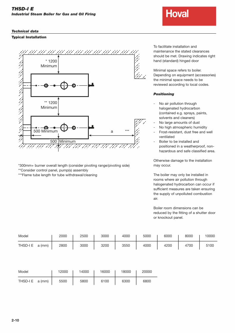
To facilitate installation andmaintenance the stated clearancesshould be met. Drawing indicates righthand (standard) hinged door
Minimal space refers to boiler.Depending on equipment (accessories)the minimal space needs to bereviewed according to local codes.
Positioning
- No air pollution throughhalogenated hydrocarbon(contained e.g. sprays, paints, solvents and cleaners)
- No large amounts of dust- No high atmospheric humidity- Frost-resistant, dust free and well
ventilated- Boiler to be installed and
positioned in a weatherproof, non-hazardous and safe classified area.
Otherwise damage to the installationmay occur.
The boiler may only be installed inrooms where air pollution throughhalogenated hydrocarbon can occur ifsufficient measures are taken ensuringthe supply of unpolluted combustionair.
Boiler room dimensions can bereduced by the fitting of a shutter dooror knockout panel.
Model
THSD-I E a (mm)
2000
2800
2500
3000
3000
3200
4000
3550
5000
4000
6000
4200
8000
4700
10000
5100
Model
THSD-I E a (mm)
12000
5500
14000
5800
16000
6100
18000
6300
20000
6800
*300mm+ burner overall length (consider pivoting range/pivoting side)**Consider control panel, pump(s) assembly***Flame tube length for tube withdrawal/cleaning
THSD-I EIndustrial Steam Boiler for Gas and Oil Firing
Technical data
Typical Installation
2-10
a ***
* 1200Minimum
** 1200Minimum
500 Minimum
500 Minimum

HovalTHSD-I EIndustrial Steam Boiler for Gas and Oil Firing
Engineering
Rules and regulations
The following rules and regulations
have to be respected:
- Hoval technical information and
installation guide
- Fire protection regulations
- National regulations concerning
permission, installation and operation of
boiler appliances. Boiler appliances
have to be installed according to
national laws and regulations and
accessory requirements.
- Besides the national and local
regulations the project specific
circumstances of the boiler supplier
have to be considered for every
application.
Water treatment/water quality
- The quality of the boiler water has to be
guaranteed according to Hoval technical
information and national guidelines.
- Hoval boilers may only be operated with
treated water. The national regulations
for the treatment of water apply for the
values to be maintained.
- Required water quality: see page 2-12.
- The water quality has to be checked
daily.
Planning, operation and
maintenance
- The heating of the feed water and the
degassing takes place in the feed water
tank (hot well).
- To increase the efficiency, especially for
natural gas operation, an economiser
can be added to pre-heat the feed
water.
- Pumps (especially horizontal rotary
pumps and warm water/condensate
pumps, NPSH pumps) need to be
installed with the necessary flow and
return pipework according to
requirements. The installation has to be
completely free of tension (anti-
vibration proof).
- Feedwater tank height must satisfy the
feed pump NPSH requirement.
- National and local rules and regulations
have to be considered for the fuel
supply. Fuel filters are highly
recommended
- The operation and water analysis data
is to be recorded daily in the operation
booklet.
- Safety valve, condensate and blowdown
connections must discharge to a safe
place.
- Filters and strainers have to be cleaned
periodically, especially if installed in
front of control devices.
- The drain of the tds, blow down,
drainage, etc has to be safely
discharged into a blowdown vessel.
- All heating components and pipework
are to be insulated in order to reduce
radiation losses.
Combustion air
- The supply of combustion air must be
guaranteed for a safe and economic
operation. There must be no possibility
of the air supply being shut off.
- Ventilation of the boiler house has to
also be provided.
- In the installation room no negative
pressure larger than 3 N/m2 is allowed.
To adhere to this demand, plan a free
area for the air supply opening of at
least 200 cm2, plus 2 cm2 per KW
output. The aspect ratio for rectangular
openings should not be more than 1.5 :1.
If the opening is louvered ensure
the free area is sufficient. National laws
have to be respected.
- Boiler houses have to be fitted with
relevant fresh air supply openings or
ducted system.
- Gas boilers are not to be installed in
rooms where halogen compounds occur
which can enter the combustion air.
Noise level reduction
The following measures for noise level
reduction are possible:
- Solid construction of boiler room
walls, ceiling and floor, installation
of silencer in fresh air supply, noise
insulation for support and bracket
of pipes.
- Installation of acoustic shroud for
the burner.
- A substantial part of the sound caused
in the combustion chamber and in the
top heating surfaces is radiated from
the flue outlet as sound transmitted by
air. In addition to this, resonance
features, depending on chimney
dimensioning and inlet, may occur
which are triggered by the oscillation of
the combustion process. These sounds
can be reduced by burner-lateral
measures, e.g. changes of flame
geometry, atomisation characteristics or
fuel throughput.
- Flue gas attenuators cause a substantial
sound level reduction. These should
usually be tuned at low frequencies of
60 - 250 Hz. Flue gas attenuators
function according to the principle of
sound absorption. The kinetic energy of
the exhaust gases is reduced by friction
requiring an increase in chimney draft in
the flue system. This has to be
considered for burner sizing. The
connection piece from the boiler to the
flue gas sound absorber has to be
gastight.
- The necessary space requirement of
approximately 1 m for the later
installation of a flue gas attenuator
should already be included when
planning.
Chimney/flue gas system
- A properly designed chimney/flue
arrangement must be provided to
match each particular application.
- To achieve a smooth discharge of the
exhaust gases from the boiler into the
chimney, the flue connection is
recommended to enter the chimney at
approximately 30-45°.
- From a length of greater than 1 m
thermal insulation is necessary.
- Adequate provision should be made to
drain off condensate from the base of
the chimney ensuring condensate does
not run back into the boiler smokebox.
2-11

HovalTHSD-I EIndustrial Steam Boiler for Gas and Oil Firing
Boiler and feed water specifications for steam boiler plants
Feed water specifications for natural circulating boilers
Boiler water specifications for natural circulating boilers
Working pressure bar <1 >1 < 22 >22 < 68
Properties colourless, clear, free from suspended matter and foam
pH-value at 25°C > 9 > 9 >9
Sum of alkaline earth elements (Ca + Mg)1 mmol/l < 0,02 < 0,02 < 0,01
°dH < 0,112 < 0,112 < 0,056
Conductivity at 25°C µS/cm see guidelines for boiler water specifications only
Oxygen (O2) mg/l < 0,1 < 0,02 < 0,02
Carbon dioxide (CO2) dissolved mg/l < 25 < 25 < 25
Iron (Fe), total mg/l - < 0,05 < 0,03
Copper (Cu), total mg/l - < 0,01 0,005
Silicate acid (SiO2) mg/l see guidelines for boiler water only
Consumption of Potassium permanganate mg/l < 10 < 10 < 10
Oil, fat mg/l < 3 < 1 < 1
1 Noted in the past at °dH, changing factor: 1 mmol/l = 5,6 °dH (German hardness).
It is not necessary to make continuous control of the following parameters: Conductivity, Oxygen (O2), Carbon dioxide (CO2)
dissolved, Iron (Fe), total, Copper (Cu), total, Silicate (SiO2), Consumption of Potassium permanganate, Oil, fat.
Working pressure bar <1 >1 < 22 >22 < 44
Properties colourless, clear, free from suspended matter and foam
pH-value at 25°C 10,5-12 10,5-12 10-11,8
Sum of alkaline earth elements (Ca + Mg)2 mmol/l < 0,02 < 0,02 < 0,01
°dH < 0,112 < 0,112 < 0,056
Conductivity at 25°C µS/cm < 5000* < 5000* < 2000*
Acid capacity KS 8,23 (p-value) mmol/l 1-12 1-12 0,5-6
Carbon dioxide (CO2) dissolved mg/l < 25 < 25 < 25
Iron (Fe), total mg/l - < 0,05 < 0,03
Silicate acid (SiO2) mg/l < 150 < 100 < 50
Phosphate (P2O4)4 mg/l 10-20 5-10 5-10
Sodium sulphate (Na2SO3)4 mg/l 5-10 5-10 3-5
(Polyamide)5 mg/l (3-5) (3-5) --
1 Take care to maintain the allowed value of acid capacity - at this point the allowed conductivity has to be lower on many
plants; for water level electrodes minimum conductivity > 5 µS/cm2 Noted in the past at °dH, changing factor: 1 mmol/l = 5,6 °dH (German hardness)3 Noted in the past as p-value, changing factor: KS 8,2 = 1 according p-value = 14 Measurements only necessary if dosing chemicals are used which contains these values5 It is recommended to use Amine (film producing) only instead of other dosing chemicals for boilers which have a small
heating load and up to maximum 16 bar working pressure. Because of the danger of foam production overdosing is not
permitted!
Boiler water quality to comply with BS2486.It is not necessary to make continuous control of the following parameters: Silicate (SiO2)
Important note: Hoval recommend that a water treatment specialist is employed to advise on each application and to carry
out routine monitoring of the feed and boiler water to ensure it remains within specification.
2-12


Hoval LimitedNorthgateNewarkNottinghamshire NG24 1JN
Tel: 01636 672711
Fax: 01636 673532
www.hoval.co.uk
Hoval ExportAustrasse 70, 9490 VaduzPrincipality of Liechtenstein
Tel: +423 399 2400
Fax: +423 399 2618
www.hoval.com
Hoval follows a policy of continued improvement and reserves the right to change specifications without notice.All dimensions are approximate.
5080
By Appointment toHer Majesty The Queen
Boiler Manufacturers & EngineersHoval Limited, Newark