how2sketch: generating easy-to-follow tutorials for
TRANSCRIPT

How2Sketch: Generating Easy-To-Follow Tutorials for Sketching 3D Objects
James W. Hennessey1 Han Liu2 Holger Winnemoller3 Mira Dontcheva3 Niloy J. Mitra1
1University College London 2KAUST 3Adobe Research
(a) easy-to-follow tutorial steps (only a few shown) (b) user sketch
step 6/28 step 7/28 step 9/28
step 15/28 step 24/28 step 28/28
Figure 1: (a) We present How2Sketch, a system that automatically generates easy-to-follow tutorials for drawing 3D models. Each generatedtutorial comes as a list of steps for drawing scaffolding primitives that help the user draw the object in correct perspective. To help the userdraw the scaffolding, the tutorial shows how to construct guidelines that anchor objects parts relative to one another. User feedback on thetutorials was positive as many created what they felt were more accurate drawings (b) User sketch from alternative viewpoint.
Abstract
Accurately drawing 3D objects is difficult for untrained individuals,as it requires an understanding of perspective and its effects on ge-ometry and proportions. Step-by-step tutorials break the complextask of sketching an entire object down into easy-to-follow stepsthat even a novice can follow. However, creating such tutorials re-quires expert knowledge and is a time-consuming task. As a result,the availability of tutorials for a given object or viewpoint is lim-ited. How2Sketch addresses this problem by automatically gener-ating easy-to-follow tutorials for arbitrary 3D objects. Given a seg-mented 3D model and a camera viewpoint, it computes a sequenceof steps for constructing a drawing scaffold comprised of geometricprimitives, which helps the user draw the final contours in correctperspective and proportion. To make the drawing scaffold easy toconstruct, the algorithm solves for an ordering among the scaffold-ing primitives and explicitly makes small geometric modificationsto the size and location of the object parts to simplify relative po-sitioning. Technically, we formulate this scaffold construction as asingle selection problem that simultaneously solves for the orderingand geometric changes of the primitives. We demonstrate our algo-rithm for generating tutorials on a variety of man-made objects andevaluate how easily the tutorials can be followed with a user study.
1 Introduction
The ability to draw real-world objects is a useful and important skillacross many disciplines. Product designers draw daily as they gen-erate and refine product ideas, fine artists may spend hours in fig-ure drawing classes learning how to replicate a shape from the realworld, while hobbyists use sketches for visual expression. Still,sketching requires skill and practice. One of the major challenges indrawing real-world objects is learning to draw what you see rather
than what you know [Edwards 1999]. A simple cylinder, for exam-ple, is known to have a circular cross-section with equal widths atthe top and bottom. However, when we actually see a cylinder, itis subject to perspective distortion: circles become ellipses whileprojected radii diminish with distance from the viewer.
Art books and tutorials provide step-by-step instructions to teachsketching [Tizon 2007; Eissen and Steur 2011]. To help with pro-portions and relative positioning, they introduce geometric con-structions, such as scaffolding primitives, and follow a coarse-to-fine approach, using prior steps as basis for subsequent ones.
Authoring such tutorials requires significant expertise and timecommitment even for trained artists. Consequently, objects andviewpoints in existing tutorials tend to be limited and are chosenby the expert, rather than the users of the tutorials. To address theseissues, we present an approach for automatically generating easy-to-follow tutorials for drawing 3D models from user specified view-points. Figure 1 shows parts of a tutorial generated by our systemand the drawing by one of our study participants based on that tuto-rial from an alternative viewpoint. Our algorithm targets man-madeobjects where part relations and proportions tend to be crucial foraccurate depiction.
Inspired by instructional books and online tutorials, we take ex-plicit steps to make a sketching tutorial easy-to-follow: (i) focuson accurate inter-part proportions and relations via a drawing scaf-fold, followed by detailing of the object contour; (ii) proceed in acoarse-to-fine fashion, where object parts are abstracted as primi-tives (e.g., cuboids, cylinders) over several levels of detail to buildup said scaffold; (iii) propose a particular drawing order among thescaffolding primitives such that those sketched later can be easilyanchored (i.e., drawn with guidance) off already drawn primitives;and (iv) provide explicit steps for the construction of guidelines toaccurately anchor the scaffolding primitives.
arX
iv:1
607.
0798
0v1
[cs
.GR
] 2
7 Ju
l 201
6

One of our key observations is that in easy-to-follow tutorials thedimensions and arrangements of object-parts tend to have ratios thatare easy to construct. For example, it is easier to construct the cen-ter line of a rectangular face compared to its one fifth line. Tutorialauthors choose to construct with such ‘easy ratios’ to simplify thedrawing process and to focus on the procedure, rather than inciden-tal and arbitrary measurements (see Figure 2). To apply this tech-nique to existing objects, our system How2Sketch proposes smallgeometric changes while keeping overall deviations from the sourcemodel minimal. Since in each step new primitives and guidelinesare anchored with respect to those drawn in previous steps, the or-dering of steps significantly affects the simplicity of ratios that canbe employed, and the geometric approximations that this incurs.This tight interdependence between ordering of primitives and theirgeometric changes makes the problem non-trivial. A further chal-lenge is to preserve the original inter-part relationships of objects,even under geometric perturbations. For example, in Figure 1 thecoaxial relationship between the mixer bowl and mixer blade is pre-served.
Technically, we map the geometric adjustment and ordering of partsto a single selection problem. We first generate a set of potentialcandidate primitives by enumerating different anchoring possibili-ties. Since anchoring requires drawing guidelines, and some guide-lines are easier to construct than others, the algorithm prefers an-choring possibilities that rely on easy-to-construct guidelines, suchas the top edge, bottom edge, center line, etc., of existing primi-tives. Our key insight is that the problem of geometric adjustmentand ordering of parts can be simultaneously solved by selecting anappropriate subset from the candidate primitives, in order to bal-ance between geometric changes and ease of constructing necessaryguidelines.
We test our algorithm on a range of examples and evaluate our al-gorithmically generated, easy-to-follow tutorials with a user study.
2 Related Work
Assisted drawing. Various applications have been proposed to as-sist a user in sketching. Some correct the user input based on ge-ometric analysis of the users input strokes [Igarashi and Hughes2001; Bae et al. 2008; Schmidt et al. 2009b], others rely on anunderlying image to guide the user [Iarussi et al. 2013; Xie et al.2014; Benedetti et al. 2014; Fernando et al. 2014], and yet otherson crowdsourced data (e.g., many sketches) to improve the usersdrawing [Dixon et al. 2010; Lee et al. 2011; Gingold et al. 2012;Limpaecher et al. 2013; Simo-Serra et al. 2016]. These methodsaim to improve the quality of the users’ strokes at a local level.Our focus is on suggesting a meaningful drawing order and easy-to-
Figure 2: A step-by-step sketching tutorial for drawing acar ©Czajkowski. The task is made simpler by breaking it into stepsand by providing guidance about part proportions and alignments.
construct guides for accurate depiction of perspective and propor-tions. Stroke correction or beautification is orthogonal to our maincontribution and may be used to complement the contour drawingphase of our tutorials. Other assisted sketching systems take as in-put 2D sketches and interpret them as 3D curve networks [Xu et al.2014]. More advanced methods [Shao et al. 2012; Iarussi et al.2015; Pan et al. 2015] use 2D input to infer 3D geometry or surfacenormals for complex shading. We focus on the automatic genera-tion of sketching tutorials, rather than automatic inference based onthe sketched curves.
Tutorials. A good tutorial greatly facilitates understanding. Manyattempts have been made to automatically generate high-quality tu-torials for different applications. A digital drawing tutorial systemwas proposed by Fernquist et al. [2011] that allows an expert tocreate tutorials for novices. Tutorial generation systems [Takagiet al. 2003; Cummmings et al. 2012] for specific sketching taskshave also been proposed, for example drawing a single scene withpre-defined objects, or ‘eyes.’ Grabler et al. [2009] developed a tu-torial system for photo manipulation tasks. How2Sketch producessketching tutorials for man-made objects automatically, rather thanrelying on an experienced artists to create them.
Drawing expertise. Tchalenko [2007] found that novices and pro-fessional artists have comparable accuracy when perform basic linedrawing tasks (straight lines and simple curves). However, in afollow-up study [Tchalenko 2009], he showed that when copy-ing complex artworks, novices made significantly more errors thanartists. The main difference in drawing strategy was that expertsdivided complex lines into easy-to-draw short segments. Schmidtet al. [2009a] found that experts made qualitatively similar errorsto non-artists, indicating that perspective drawing is hard, even fortrained users. Particularly for off-axis viewing angles, drawing er-ror increased significantly. In an observational study, Grimm [2011]found that artists commonly used a coarse-to-fine strategy startingwith blocking shapes and finishing by drawing detailed items at theend. How2Sketch assists the user by breaking the drawing processup into basic steps that are easy to execute and by explicitly indi-cating vanishing line directions.
Line drawings. Many methods for generating stylized artistic ren-derings of objects have been proposed (see [Kyprianidis et al. 2013]for a survey). We leverage stylization to visually distinguish thevarious line types of our tutorials (perspective lines, guides, con-tours, etc). Other researchers investigated which features artiststypically draw to convey 3D shape [DeCarlo et al. 2003; DeCarloet al. 2004; Burns et al. 2005; DeCarlo and Rusinkiewicz 2007]. Wedisplay suggestive contours computed on the optimized object toaid the user in adding final details to their drawing. Fu et al. [2011]and Liu et al. [2014] infer plausible contour ordering from 2D and3D inputs, respectively. While the derived sequences are plausi-ble, they are not tailored for tutorials and do not provide specificguidelines to make them easy to follow.
3 Learning How to Sketch
To inform the design of How2Sketch we studied several drawingbooks [Edwards 1999; Eissen and Steur 2007; Eissen and Steur2011], visited a number of sketching websites (e.g., Sketch-a-Day),carried out an expert interview with a professional artist, and tooka drawing course.
Through this process we found that effective tutorials for drawing3D objects typically include the following:
• Parts are approximated by geometric primitives: Plane, cubesand cylinders are heavily used to approximate shapes. Theyare easy to construct and verify visually.

segmentedinput model
generateprimitives & relations
createprimitive candidates
selectvalid + desirable cand.
create tutorial view point
Figure 4: System Overview. Starting from an input part-level segmented model and a user-specified viewpoint, How2Sketch generateseasy-to-follow step-by-step tutorials. The system automatically makes subtle geometric modifications to simplify the resultant tutorial.
• Steps are coarse-to-fine: First, the overall object is scaffoldedwith approximate shapes, and then, finer contour details areadded. Primitives are drawn sequentially, in a particular order.
• Anchor shapes to each other: Shapes are drawn with respectto previously drawn shapes, to aid with correct placement andproportions. Instructions for positing shapes relative to eachother use simple measurements (e.g., draw box half way downthe side, draw circle in the center of the rectangle), etc.
• Vanishing lines for perspective: Vanishing points are explic-itly indicated to aid the user to draw correctly.
How2Sketch supports the above tutorial features as follows:
(a) Scaffolding Primitives. How2Sketch utilizes scaffolding prim-itives to geometrically approximate each segmented object part.The system supports planes, cuboids, cylinders, and truncated pyra-mids, as they allow for planar guidelines to be used, which are sim-ple to construct, and cover a wide range of shapes. In addition toscaffolding, we guide users in drawing ellipses to better approxi-mate some shapes.
(b) Ordering. Our algorithm provides the relative ordering of thescaffolding primitives. Further, How2Sketch offers detailed, se-quenced instructions for constructing primitives.
(c) Placement, Alignment, and Proportions. We support a setof coplanar guidelines (see Figure 3). Given a face ABCD, itsdiagonals help construct the 1⁄2 line EF (Figure 3a). Two levelsof 1⁄2 lines produce a 1⁄4 line GH (Figure 3b); while intersecting adiagonalBD with lineCE produces a 1⁄3 line IJ (Figure 3c). Simi-larly, we support extrusion towards a vanishing point as in Figure 3d
(a) 1/2 guide (b) 1/4 guide (c) 1/3 guide (d) extend guide
(e) alignment guide (f) perspective guide
A A A A
B
C
BBB
CCC
D D D D
E E EG
FFF
H
I
J
K
L
M
N
N’
M’
Figure 3: Our system supports different forms of guidelines fordrawing coplanar proportions (a-d), for anchoring alignments (e),and for previewing 2-point perspectives (f). See Section 3.
where ABCD is extended by reflection to form BCLK such thatAB = AK. Finally, we also support alignment, as in Figure 3e,M ′N ′ is aligned with MN .
(d) Perspective. To provide perspective information, we show thevanishing points (if within the drawing area) and also show thevanishing lines leading to them (Figure 3f). How2Sketch supportssketching in 2-point and 3-point perspective.
4 Generating Sketch Sequences
Given a 3D object (S) segmented into parts and a desired viewpoint,our goal is to establish an easy-to-follow sequence for drawing theobject, starting with the scaffolding and progressing to the contourdetails. We make it easier to draw the scaffold by actively makingsmall part-level geometric changes to facilitate relative anchoringusing a set of guidelines.
As described in Section 3, we have adopted simple procedures toaccurately draw guidelines at easy-to-construct ratios (1⁄2, 1⁄3, 1⁄4, 1×,2×, etc). Object part placements and sizes in the original mod-els, however, rarely conform to such ratios. Hence, we propose tomodify object parts, so that they end up with part relationships thatare easy to draw. We motivate this choice twofold: (i) Scaffoldingprimitives in tutorials like those generated by How2Sketch are al-ready approximations of real geometry and thus contain a measureof error. Some of this error can actually be compensated by adjust-ing the fit of contours within the scaffold. (ii) Accurate estimationof lengths and ratios is difficult, even for experts, so errors are al-most unavoidable. By enforcing that parts relate via simple ratiosfor which reasonable geometric constructs can guide the user, theoverall drawing error is unlikely to increase significantly beyondthe unguided case.
Our algorithm proceeds in three main stages (see Figure 4): (i) gen-erating part-level primitives and encoding inter-primitive relations;(ii) creating primitive candidates based on various inter-primitiveanchorings strategies; and (iii) selecting a valid and desirable set ofprimitives among the candidate selections. The result implicitly en-
Table 1: Notation table.
symbol denotes
S input part-segmented modelPi primitive corresponding to the i-th part of S
Ri,j relation between primitive pairs (Pi, Pj)
Ckj→i candidate for the i-th part primitive with (anchoring) parent from the
j-th part primitive, where k denotes the k-th such instanceC∗i set of all the candidate primitives generated for part primitive Pi
χ(X) indicator variable corresponding to the selection ofXΛ assignment of indicator variables denoting a set of selected candidates

(a) (b)
cylinder
plane
cuboid
truncatedpyramid
commonbisector plane
Figure 5: Given a part-segmented input model S (top-left inset),we abstract the parts as different primitives (a) and identify inter-part relations. For example, here the mixer bowl and mixer headprimitives share a common bisector plane.
codes how to geometrically modify each part (both their dimensionand placement), and in which order to draw them. Intuitively, ouralgorithm produces an easy-to-follow primitive drawing sequenceat the cost of deviating from the original geometry in a controlledfashion. We now elaborate each step. Please refer to Table 1 forsymbols used in the following.
4.1 Generating Primitives and Inter-part Relations
We abstract model parts by primitive shapes. In our implementationwe support planes, cuboids, cylinders, and truncated pyramids (seeFigure 5a). (Note that in our visualization we show axis-alignedbounding box for cylinders as the box faces are used for providingguidance for drawing ellipses.) For each part of the input model S,we use least-squares to fit (axis-aligned) different primitive typesand take the one with the least residue. In case of ties, we preferthe simpler primitive. We denote the primitive for the i-th part asPi (type of primitive is not explicitly indicated in this notation).
Man-made objects, which are our target objects, often have domi-nant inter-part relations. We found it highly desirable to preservesuch relations in the generated tutorials. Hence, we first detect suchinter-part relations and later preserve them in the generated tutori-als. We simply test (see [Mehra et al. 2009]) each pair of primitivesPi and Pj for any relations. In our implementation, we considercoplanar, coaxial, and common bisector plane relations. In case ofmultiple relations between a pair of primitives, we prefer commonbisector plane over coaxial over coplanar. We represent a relationusing a binary variable Ri,j where i and j respectively denote theprimitives Pi and Pj (type of relation is not explicitly indicatedin this notation). If a relation is present, we mark Ri,j = 1, andRi,j = 0 otherwise. Figure 5 shows some examples.
4.2 Creating Candidate Primitives
We now describe the candidate primitive generation step that cre-ates additional primitives based on possible anchoring strategies.We use C∗i to denote the set of all the candidate primitives gen-erated corresponding to primitive part Pi. Since the the originalprimitive is always a candidate, we start by C∗i := {Pi}. We gen-erate candidate primitives in three stages:
(i) For each pair of primitives Pi and Pj , we generate candidates ofthe form Ck
j→i, where j → i indicates that a candidate is generatedfor primitive part Pi and is anchored off Pj with k denoting dif-ferent anchoring possibilities. For example, parts can be anchoredbased on different guidelines described in Section 3 for differentface- or plane-based anchors. We append these candidates to therespective candidate sets as: C∗i ← C∗i ∪ {C1
j→i, C2j→i, . . . } (see
Figure 6b).
(ii) For each pair of primitives (Pi, Pj) sharing a relation of the
(a) (b)
(c) (d)
1
2
3
4
Figure 6: Starting from initial primitives P1, P2, P3, P4, for eachpair of primitives we generate several candidate primitives. Forexample in (b), we show the primitives generated for P3 using P4
as parent, indicated as different instances P k4→3 shown in different
dotted/solid brown. Relations are restored leading to further newprimitives, for example in (c) the green primitive was lifted to re-store coplanarity with the brown primitive. Finally, we also havesecond level primitives. As shown in (d), the new brown primitiveleads to a new primitive for P1. This is an illustrative figure in 2Dwith only some of candidate primitives shown for simplicity.
form Ri,j , we add additional primitives to their candidate sets torestore the relations. Specifically, corresponding to a candidate ofthe form Ck
j→i (created in stage (i)), we create a new candidate ofthe form Ck′
i→j such that Ckj→i ↔ Ck′
i→j are similarly related as inPi ↔ Pj . We append all such relation-based additional candidateprimitives to the respective candidate sets, i.e., C∗i ← C∗i ∪ Ck′
i→j
(see Figure 6c).
Note that in the above a candidate is allowed to be anchored fromone or multiple parents, as each axis can be independently an-chored. Additionally a candidate can be partially unguided (e.g.,the width and length of cuboid is guided but the height is not) orcompletely unguided (e.g., it is simply the input primitive) (see Fig-ure 6). We defer further details to the implementation section.
(iii) We allow second-level anchors, i.e., candidate primitives asgenerated above are allowed to act as anchors for other primitives.To this end, we simply iterate one more time stage (i) and (ii) (seeFigure 6d). Note that before starting this step, we remove the can-didate primitives with large changes in geometry or relative place-ments (more details in the implementation section).
At the end of this stage, we have a set of candidates for each part ofthe input model resulting in the super set of candidate primitives ofthe form {C∗i} (see Figure 7).
4.3 Selecting Candidate Primitives
Having generated multiple candidates, our remaining task is to se-lect a set valid and desirable candidates, as explained next.
Valid candidate sets. We first characterize the notion of valid se-lections. We use indicator variables χ(X) to denote if a candidateprimitive X is selected (i.e., χ(X) = 1) or not (i.e., χ(X) = 0).We have χ(Ck
j→i) ∈ {0, 1} for each Ckj→i ∈ C∗i. Let Λ denote
a particular assignment for the indicator variables for all the candi-date primitives.
Among the various possible selections, not all the subsets of candi-dates of the form Λ constitute valid selections. A valid selection ofcandidates should satisfy three conditions:(1) for each part of S, only one candidate primitive should be se-

Figure 7: From a set of candidate primitives (left), our algorithmselects a subset of primitives that is valid and desirable as shownon the right. The selection implicitly encodes in which order todraw the primitives and also how to change each primitive (sizeand/or placement) such that the resulting tutorial is easy to con-struct. Please refer to the text for details.
lected;(2) if a selected candidate primitive is anchored off one or moreparent (candidate) primitives, then its parent primitive(s) must alsobe selected;(3) if any two primitives Pi and Pj share a relation, then their corre-sponding selected candidate primitives should also respect the samerelation. (Note that by (1) implies that each primitive should have aunique selected candidate associated with it.)
We now express the above conditions in terms of the indicator vari-ables in Λ.(a) We encode (1) as∑
j,k
χ(Ckj→i) = 1 ∀i. (1)
(b) We encode (2) as a quadratic constraint involving the binaryselection variables as
χ(Ckj→i)χ(Cj)− χ(Ck
j→i) ≥ 0 (2)
for each dependent pair Ckj→i ∈ C∗i and its parent Cj . Note that
this condition disallows χ(Ckj→i) = 1 AND χ(Cj) = 0, but al-
lows any of the other three assignments involving χ(Ckj→i) and
χ(Cj).(c) We now encode (3). Let two primitives Pi and Pj share a rela-tion, i.e., Ri,j = 1. Let C∗i = {C1
∗i, C2∗i, . . . } be all the generated
candidates for primitive Pi and similarly C∗j = {C1∗j , C
2∗j , . . . }
for primitive Pj . Then for each pair of the form Ck∗i ∈ C∗i and
Ck′∗j ∈ C∗j that does not share the same relation as Ri,j , we require
χ(Ck∗i)χ(Ck′
∗j) = 0. (3)
This condition disallows χ(Ck∗i) = 1 AND χ(Ck′
∗j) = 1, i.e., theycannot be jointly selected as these candidate primitives do not sharethe same relations as of their respective primitive parts.
Thus, a selection Λ is valid if Equations 1-3 are all satisfied. Amongall such valid selection sets, we next determine which one is mostdesirable. Figure 7 shows a set of candidate primitives and a validselection.
Sequencing sketching as a selection problem. We balance the er-ror due to making changes to the geometry with difficulty of draw-ing arising from anchoring. In other words, an unanchored part ismore difficult to draw compared to an anchored part – this is a keyhypothesis of this work. We indicate this difficulty of drawing costas Ee(Ck
j→i) with a lower cost denoting easier to draw (see laterfor details). The total cost is expressed as:
Edifficulty(Λ) :=∑i,j,k
χ(Ckj→i)Ee(Ck
j→i). (4)
Selecting any primitive, however, incurs an associated error thatwe indicate as Ed(Ck
j→i) due to deviation from original geometry(see later describe how we measure Ed). So, the total data cost ofselecting a set of primitives is:
Eadjust(Λ) :=∑i,j,k
χ(Ckj→i)Ed(Ck
j→i) (5)
with a higher cost indicating larger geometric deviations from theoriginal parts.
Thus, we arrive at the final formulation for desirable selection as,
minΛ
(Eadjust(Λ) + Edifficulty(Λ)) (6)
subject to Equations (1)-(3) to ensure a valid selection. Thus, wehave formulated our problem as a quadratically constrained linearprogram.
Error functions. The above formulation requires metrics for Ee
and Ed. While various metrics may be substituted, we used thefollowing in our implementation.
For the difficulty of drawing term Ee(Ckj→i), we associate a higher
cost for anchors that are harder to replicate (e.g., requiring moreconstruction lines). Specifically, we set the cost to the number ofguidelines divided by the area of the parent plane where construc-tion lines are to be drawn. This encourages fewer guides but alsousing planes/faces with larger areas for drawing sketch guides. (Theeffect of viewpoint is only considered at runtime as discussed inSection 5).
For the data error Ed(Ckj→i), we sum the changes in length along
each axis, normalized by the original axis length, with the transla-tion of the midpoint of each axis, again normalized by the input axislength. For an unguided axis we set the data error to the maximumof 2 to discourage unguided candidates.
Final drawing order. The solution to the above optimization di-rectly gives us both the ordering and the modifications of the parts.Note that the above solution may only return a partial orderingamong the candidates primitives. This implies that the relativedrawing order among of certain primitives are not specified. Webreak such ties only at runtime once the user selects a view as de-scribed in Section 5.
A note about greedy alternative: An alternative algorithm is togreedily consider primitive pairs and snap them relative to nearestguidelines. Such an adhoc strategy fails to take care of the sec-ond level candidates, and produces an inferior solution. More im-portantly, this approach does not provide any meaningful orderingbased on ease of drawing, which is a key focus of our problem.
4.4 Implementation details
We now clarify some additional implementation details. Most ofthese are choices we made in our implementation, and can be re-placed by multiple comparable alternatives.
Primitives that are not well approximated by one of the currentlysupported ones can be represented as a custom primitive (e.g., line)but such primitives cannot be part of our optimization step. Insteadafter our optimisation step their relative positioning is updated andwhen sketched they are unguided. Alternatively, the user can ap-proximate them by their bounding box primitive.
The candidate primitive generation works in two steps: first, we usethe coplanar relations to generate candidate planes cki→j , and thendepending on the primitive type we combine the planes to createa complete primitive Ck
i→j (here, lowercase c for candidate plane

rather than complete primitive that uses uppercase C). This choiceunifies candidate primitive generation across primitive types (recallcylinders are processed based on their axis-aligned bounding box).
For each pairwise coplanar relation Ri,j we have two participatingplanes in Pi and Pj : at this stage the relation is undirected andwe produce candidate planes using both combinations ckj→i andcki→j . To generate a candidate plane, each axis is considered in-dependently then all combinations are combined to create planescki→j . An axis can be anchored by the parent plane using the endpoints of the same axis. This means there are several anchoringpossibilities. For example, anchoring the vertical axis of Pi on Pj
might involve anchoring the top edge of Pi to the 1⁄3 line of Pj andthe bottom edge Pi to the bottom edge of Pj . An alternative mightbe to anchor the top edge of Pi to the 1⁄3 line of Pj and the bottomedge Pi to 1⁄4 line of Pj . We initially generate all candidates butto reduce the number of candidates to select from we discard thosewhere an axis length or translation change of more than 10% of theinput length.
With all the candidate planes generated using all the pairwise rela-tions we generate complete primitives by combining the differentplanes based on the primitive type. To generate a complete cuboidprimitive, for example, we find the missing height axis from one ofthe other planes to complete the primitive. For truncated pyramidswe combine top and bottom planes with a height axis to make atruncated pyramid. To generate second level candidates, we repeatthis process but use the first level candidates as the parent primi-tives.
We use the Gurobi linear Solver [Gurobi Optimization 2015] tosolve the quadratically constrained LP as described above. Typi-cally the solver takes 1-2 minutes in the presented examples.
5 Presenting Sketch Sequences
The sequence generated in Section 4 provides primitive ordering,sketching guidelines, and adjusted part geometry for drawing thescaffolding of the object. How2Sketch tutorials can be adapted fur-ther based on the user chosen viewpoint and user indicated drawinglevel (novice/apprentice/master), which can be controlled interac-tively. Our custom viewer indicates when guidelines can be erasedand provides hints for drawing in perspective and object contours.
Viewpoint. We use the specified viewpoint to customize the tutorialas follows: (i) Although primitive ordering is determined based onanchoring strategies, multiple primitives can anchor from the sameparent, resulting in a tie. We break such ties in ordering by firstchoosing the primitive that is closest to the user from the indicatedviewing position. (ii) The selected viewpoint can make some guide-lines cumbersome to draw because of limited space on the projectedarea of a primitive face. We identify such instances by threshold-ing based on Ap/k, where Ap indicates the projected area and kthe number of guides necessary to draw the primitive. If a primi-
Novice Apprentice
Extend by 1/2
Master
Figure 8: User ability. Users specify drawing level(novice/apprentice/master) which determine the number of inter-mediary guides presented for each step. For the ‘extend by 1/2’step, novices (left) are shown 9 guidelines, apprentices (center) 6guidelines, and masters (right) 3 guidelines.
Step 1 Step 2 Step 3
Figure 9: Guide lifetime. Guides first appear in orange (left). Insubsequent steps guides that are no longer required are removed,while those that are to be reused are marked in blue (middle, right).
tive falls below this threshold, we ask the user to simply ‘eyeball’the primitive without drawing intermediate guides. (iii) Finally, asegment that is occluded and its primitive does not help anchor anyother visible primitive is deemed unnecessary and hence is left outfrom the tutorial.
User ability. We adapt our tutorials to different sketching abilitiesby classifying the various guidelines as suitable for novice, appren-tice, or master users. For example, dividing a face of a primitiveinto halves requires three guidelines. A novice is shown all thethree, an apprentice only the 1⁄2 line itself, and a master is not pro-vided with any intermediate guidance. Note that in all cases, theuser is instructed to divide the highlighted face into half by a textlabel in the viewer (see Figure 8).
Guide lifetime. In order to reduce the amount of guidelines ona sketch at any point in time, we determine each guide’s lifetimeto inform the users when a guide can be safely erased. To thisend, we first go over the list of generated guidelines to identify theequivalent ones, and store their lifetime, i.e., when they first appearand when they are last used. During the tutorial, a guideline isdrawn in orange when it first appears. If the guideline is used inany later step, it is changes to blue. After the last step a guideis used, it is no longer shown. As a result, users do not have tounnecessarily erase/redraw guides, and thus reduce clutter as theysketch (see Figure 9).
Vanishing points and ellipses. Vanishing lines and vanishingpoints are indicated with respect to the paper boundary (shownas green corners) to help users better position the lines. We ad-ditionally guide users in sketching ellipses on a primitive face byusing guides to the vanishing points. These guides intersect withthe edges of the face at the perspective mid-points, which are thepoints where the ellipse should touch the face of the primitive.
Contour ordering. Once the user has sketched the scaffolding andellipses, we guide them to sketch the contours. We use suggestivecontours [DeCarlo et al. 2003] computed on the modified underly-ing model segments (the contours are computed at a segment level).The contour segments are progressively displayed per segment, fol-lowing the order determined by the primitives. Already drawn partsare used to determine occlusion for the new primitives, thus reduc-ing clutter (see Figure 1).
Interface. How2Sketch tutorials can be presented in many differentforms. They can be navigated manually using an our interface; theycan be printed (see supplementary material), or sequenced into avideo.
6 Results and Discussion
We used How2Sketch to generate sketching tutorials for four man-made objects - a Digital SLR Camera, Kitchen Mixer, Train andPaint Roller. For these models, numerous tutorials depending onviewpoint and user ability can be generated. Parts of the tutori-als are shown in Figure 10 (see supplementary material for full se-quences). Each tutorial takes between 15 and 45 minutes to com-

(d) train(a) camera (c) mixer(b) roller
step 4/24 step 2/14 step 5/27 step 2/34
step 8/24 step 4/14 step 7/27 step 5/34
step 12/24 step 5/14 step 9/27 step 6/34
step 15/24 step 6/14 step 11/27 step 9/34
step 17/24 step 7/14 step 19/27 step 14/34
step 21/24 step 10/14 step 23/27 step 23/34
Figure 10: Example step-by-step tutorials generated by our system: (a) and (b) were generated in the master-user setting, while (c) and (d)were generated in the novice-user setting. Please refer to the supplementary materials for complete examples.

(a) original models (b) modified models Figure 11: (Left) Original models. (Right) Subtle changes pro-posed by our algorithm in order to make the objects easier to draw.
plete due to their varying complexity. The small changes madeto the input geometry by the method are illustrated in Figure 11.As desired, the alterations to geometry are subtle but now enablesimple anchoring strategies based on the altered segment boundingboxes (also shown).
As demonstrated in Figure 10, our tutorials follow a coarse-to-finestrategy, starting with a single primitive that can be used to anchorsubsequent primitives. Figure 10a shows excerpts from a tutorialsequence with master user ability. Here, the grip is anchored onthe edges of the camera body and a 1⁄4 guide. Additionally, the gripand flash are both extended by one half the depth of the main body.The lens, an example of a second level anchoring, uses the flash foranchoring by extruding 1×. Guides for ellipses are provided beforecontours are drawn.
In the paint roller tutorial in Figure 10b the handle anchors the rollerusing the common bisector plane. The top edge of the roller is 1×the length of the handle. The bottom edge is 1⁄2× the length of thehandle but due to the limited projected area and number of guidesotherwise required, the step is unguided (as per Section 5).
Figures 1 and 10c both show novice ability tutorials for the foodmixer but from different viewpoints. The plane primitive for thebase of the mixer anchors the bowl using a planar relation and 1⁄2guide. The common bisector plane between the base and the mainbody of the mixer is used for anchoring the length of the main body.The bisector plane is first drawn before being extended in both di-rections to create the cuboid primitive. The Mixer’s stand is anexample of a primitive with two parents, being anchored off boththe main body and base.
The train example, Figure 10d, anchors the second carriage as 1×
the length of the first carriage and the top edge of the wheels usingthe 1⁄4 guide on the vertical axis of the first carriage. The driver’scompartment is unguided.
Limitations. How2Sketch only makes small changes to the in-put geometry. However, small gaps between object parts can haveimportant semantic meaning. An example of this can be seen inFigure 11 where the main body of the mixer and the stand sepa-rate slightly in the adjusted version. We know these two segmentswould be joined by a hinge making such an adjustment unrealis-tic. Symmetry or regular structure can similarly be lost from thesmall geometry changes. An example of this is the roller in Figure11, which ceases to be a perfect cylinder. Note that most of theseviolations are difficult to spot unaided and tend to get masked bydrawing inaccuracies. Finally we find relations from the input seg-ments but do not allow adjustments in geometry to create a relationthat was not already present. In the future, we might enable suchchanges to allow for an even wider range of candidates.
7 Evaluation
To evaluate the effectiveness of the How2Sketch tutorials, we com-pare to a simple step-by-step tutorial that shows scaffolding prim-itives for each part of the object but does not simplify the sizes orlocations of the primitives to make them easier to draw. In this Ba-sic tutorial type, the scaffolding primitives are shown in order fromlargest to smallest with a base primitive anchored to the groundplane. No guidelines are shown. Please see the supplemental mate-rials for the complete tutorials used in the study.
Preliminary Study. We conducted a preliminary study with 8 par-ticipants comparing an earlier version of How2Sketch with the ba-sic tutorial type. User responses to questions about satisfactionwith their drawing, perceived accuracy of their drawing, and experi-ence with the tutorial were significantly higher for the How2Sketchtutorial compared to the Basic tutorial. Additionally an ANOVAacross tutorial type and object drawn revealed a significant effectof tutorial type on satisfaction, accuracy, and experience ratings (p< 0.022 in all cases). Despite this positive feedback we did notobserve an improvement in drawing quality across tutorial type.Based on the preliminary study observations and user feedback, thecurrent version of How2Sketch introduces a wider range of primi-tives, indicates guide lifetime, adapts tutorials based on user ability,and uses relations for candidate generation.
Participants. We recruited 10 participants (ages 18-55+, 6 men)with varied expertise in drawing. Two participants reported neverdrawing. Four reported drawing once in a while. Six reported draw-ing at least once a month. Three had taken college-level art classesor private/non-accredited art classes. When asked (free-form) whatthey found most challenging about drawing, 4 mentioned perspec-tive, proportions, scale, and relative positions. When asked to ratetheir drawing skills on a scale of 1 (poor) to 5 (great), only 4 peoplerated their drawing skills above 2.
Methodology. In advance, each participant filled out an introduc-tory online questionnaire about their experience with drawing realobjects. Upon arrival, each participant was told that they will beasked to draw two objects, a camera and a mixer, using two differ-ent tutorials. Participants always followed a How2Sketch tutorialfirst to disadvantage How2Sketch to any learning effect. The twoobjects (camera and mixer) counter-balanced with half of the par-ticipants using the Basic tutorial type for the camera and half usingthe How2Sketch tutorial for the mixer. The study had 4 conditions(2 objects x 2 tutorial types). The How2Sketch tutorial was set tothe novice ability for all participants.
Before the How2Sketch tutorial, participants were given a written

Figure 12: Average user ratings for satisfaction, perceived ac-curacy, enjoyment, and ease of drawing were all higher for theHow2Sketch tutorials than for the basic tutorials. Showing stan-dard error of mean (SEM) bars for N = 10.
handout (see supplemental material) that described how to drawconstruction lines for 1⁄2, 1⁄4, and 1⁄3 guidelines and extending planes(see Figure 3). This written tutorial was designed to give them con-text for what they would encounter in the How2Sketch condition.
Both the Basic and How2Sketch tutorials were followed using aMacbook Pro 13” laptop; participants used the trackpad to advanceforward and backward through the tutorial. All drawings were doneon paper. Each participant was given two pencils (HB, 0.3mm and0.7mm). They were allowed to use a provided straight-edge anderaser. For creating each drawing, the participants were given asheet of paper that included the vanishing points and the groundplane of the first primitive. This initial calibration allowed us tomore easily compare drawings across users. All users drew thescaffolding primitives first on the calibrated paper. For drawingthe final contours of the object, the moderator attached a transpar-ent sheet to the paper with the scaffolding. This allowed us to moreeasily compare both the contour drawings and the scaffolding prim-itives across users.
Participant filled out a questionnaire after drawing each object, in-dicating their level of satisfaction with their drawing (1 - not at all,5 - very much), perceived accuracy of their drawing (1 - not at allaccurate, 5 - very accurate), enjoyment with the tutorial experience(1 - not at all, 5 - very much), and how ease the tutorial steps wereto follow (1 - not at all easy, 5 - very easy). They also gave free-form responses about what they liked about each tutorial type andhow it could be improved. At the end of the study, subjects wereasked which tutorial type they preferred (Basic or How2Sketch). Inthe study itself we referred to the Basic tutorial type as the tuto-rial without guides and the How2Sketch tutorial type as the tutorialwith guides.
All participants were given a $25 gift card for their time.
Feedback. Nine out of ten participants preferred the How2Sketchtutorial over the Basic tutorial. User responses to questions aboutsatisfaction with their drawing, perceived accuracy of their drawing,enjoyment of the drawing process, and ease of following tutorialswere all higher for How2Sketch than the Basic tutorial (Fig. 12).
An ANOVA across tutorial type and object drawn reveals a strongsignificant effect of tutorial type on accuracy and ease of followingtutorial (p<0.003), significant effect on enjoyment (p<0.034), andmarginally significant effect on satisfaction (p<0.058). The objectdrawn did not have an effect on any measure, despite their varyingdifficulty, and there was no interaction between tutorial type andobject drawn.
Freeform feedback echoed the ratings. Participants enjoyed usingthe guides as it gave them more confidence in their accuracy. Oneparticipant said “It was satisfying drawing the guides and gettingthe proportions right. It was then so much easier to draw the final
Figure 13: User Study Sketches: User sketches all overlaid on theobject they drew sketches from following basic tutorial (left) showmuch greater variation in proportions and alignment than sketchesfrom following How2Sketch tutorials (right).
sketch using the blocks (scaffold) for guidance”. Users also hadsuggestions for improvements to the system with several asking forfurther guidance with perspective.
Sketch quality. Figure 13 overlays the registered user sketchesfrom the different conditions on the original model for the condition(e.g How2Sketch model after part level adjustments). While thereappears to be variation in contour placement in both tutorial typesthe variation in the basic tutorial sketches is greater.
In the camera tutorials the basic version starts with the ground planefor the lens and How2Sketch with the ground plane of the mainbody. With this anchoring in the basic tutorial sketches, the widthand length of the lens are accurate. However, the lens height and theother three primitives have a variety of errors in proportion and partplacement. Comparing with How2Sketch sketches, there are simi-lar variations in the height of the main body. However, the guidedsteps for the grip and lens shows decent convergence in position-ing across users. For the Mixer sketches - where both tutorials startwith the base plane of the mixer - there is much more consistencyof object part placements across users.
To further validate these findings, we conducted an additional userstudy using Amazon Mechanical Turk (AMT). In the study, we pre-sented users with two sketches of the same object type overlaid andregistered to their condition specific model (see supplementary ma-
MIXER object CAMERA object
basic
How2Sketch
basic
How2Sketch
num
ber
of pairw
ise c
om
parisons
num
ber
of pairw
ise c
om
parisons
probability of being judged more accurate probability of being judged more accurate
Figure 14: Bradley-Terry Model for the Mixer and the CameraSketches produced by users of our tutorials and evaluated by an-other user study with Amazon Mechanical Turk rankers.
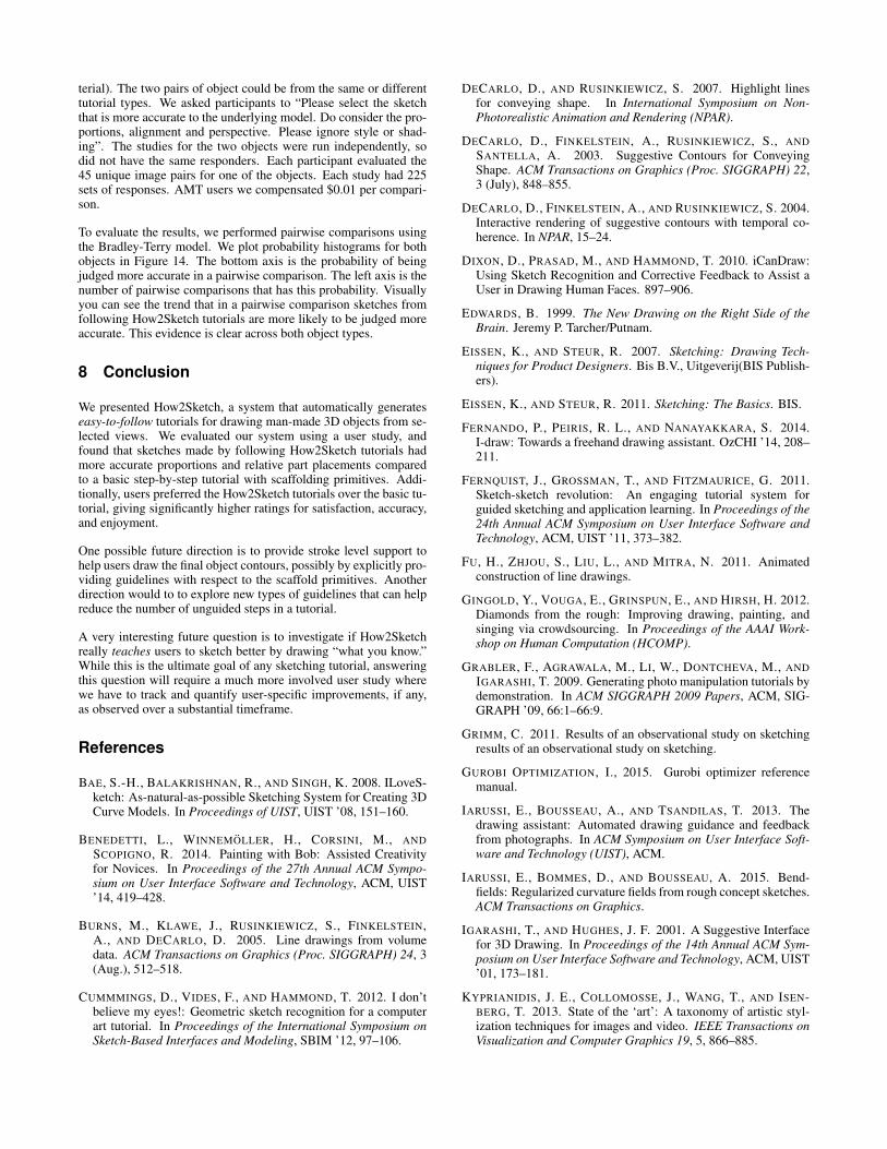
terial). The two pairs of object could be from the same or differenttutorial types. We asked participants to “Please select the sketchthat is more accurate to the underlying model. Do consider the pro-portions, alignment and perspective. Please ignore style or shad-ing”. The studies for the two objects were run independently, sodid not have the same responders. Each participant evaluated the45 unique image pairs for one of the objects. Each study had 225sets of responses. AMT users we compensated $0.01 per compari-son.
To evaluate the results, we performed pairwise comparisons usingthe Bradley-Terry model. We plot probability histograms for bothobjects in Figure 14. The bottom axis is the probability of beingjudged more accurate in a pairwise comparison. The left axis is thenumber of pairwise comparisons that has this probability. Visuallyyou can see the trend that in a pairwise comparison sketches fromfollowing How2Sketch tutorials are more likely to be judged moreaccurate. This evidence is clear across both object types.
8 Conclusion
We presented How2Sketch, a system that automatically generateseasy-to-follow tutorials for drawing man-made 3D objects from se-lected views. We evaluated our system using a user study, andfound that sketches made by following How2Sketch tutorials hadmore accurate proportions and relative part placements comparedto a basic step-by-step tutorial with scaffolding primitives. Addi-tionally, users preferred the How2Sketch tutorials over the basic tu-torial, giving significantly higher ratings for satisfaction, accuracy,and enjoyment.
One possible future direction is to provide stroke level support tohelp users draw the final object contours, possibly by explicitly pro-viding guidelines with respect to the scaffold primitives. Anotherdirection would to to explore new types of guidelines that can helpreduce the number of unguided steps in a tutorial.
A very interesting future question is to investigate if How2Sketchreally teaches users to sketch better by drawing “what you know.”While this is the ultimate goal of any sketching tutorial, answeringthis question will require a much more involved user study wherewe have to track and quantify user-specific improvements, if any,as observed over a substantial timeframe.
References
BAE, S.-H., BALAKRISHNAN, R., AND SINGH, K. 2008. ILoveS-ketch: As-natural-as-possible Sketching System for Creating 3DCurve Models. In Proceedings of UIST, UIST ’08, 151–160.
BENEDETTI, L., WINNEMOLLER, H., CORSINI, M., ANDSCOPIGNO, R. 2014. Painting with Bob: Assisted Creativityfor Novices. In Proceedings of the 27th Annual ACM Sympo-sium on User Interface Software and Technology, ACM, UIST’14, 419–428.
BURNS, M., KLAWE, J., RUSINKIEWICZ, S., FINKELSTEIN,A., AND DECARLO, D. 2005. Line drawings from volumedata. ACM Transactions on Graphics (Proc. SIGGRAPH) 24, 3(Aug.), 512–518.
CUMMMINGS, D., VIDES, F., AND HAMMOND, T. 2012. I don’tbelieve my eyes!: Geometric sketch recognition for a computerart tutorial. In Proceedings of the International Symposium onSketch-Based Interfaces and Modeling, SBIM ’12, 97–106.
DECARLO, D., AND RUSINKIEWICZ, S. 2007. Highlight linesfor conveying shape. In International Symposium on Non-Photorealistic Animation and Rendering (NPAR).
DECARLO, D., FINKELSTEIN, A., RUSINKIEWICZ, S., ANDSANTELLA, A. 2003. Suggestive Contours for ConveyingShape. ACM Transactions on Graphics (Proc. SIGGRAPH) 22,3 (July), 848–855.
DECARLO, D., FINKELSTEIN, A., AND RUSINKIEWICZ, S. 2004.Interactive rendering of suggestive contours with temporal co-herence. In NPAR, 15–24.
DIXON, D., PRASAD, M., AND HAMMOND, T. 2010. iCanDraw:Using Sketch Recognition and Corrective Feedback to Assist aUser in Drawing Human Faces. 897–906.
EDWARDS, B. 1999. The New Drawing on the Right Side of theBrain. Jeremy P. Tarcher/Putnam.
EISSEN, K., AND STEUR, R. 2007. Sketching: Drawing Tech-niques for Product Designers. Bis B.V., Uitgeverij(BIS Publish-ers).
EISSEN, K., AND STEUR, R. 2011. Sketching: The Basics. BIS.
FERNANDO, P., PEIRIS, R. L., AND NANAYAKKARA, S. 2014.I-draw: Towards a freehand drawing assistant. OzCHI ’14, 208–211.
FERNQUIST, J., GROSSMAN, T., AND FITZMAURICE, G. 2011.Sketch-sketch revolution: An engaging tutorial system forguided sketching and application learning. In Proceedings of the24th Annual ACM Symposium on User Interface Software andTechnology, ACM, UIST ’11, 373–382.
FU, H., ZHJOU, S., LIU, L., AND MITRA, N. 2011. Animatedconstruction of line drawings.
GINGOLD, Y., VOUGA, E., GRINSPUN, E., AND HIRSH, H. 2012.Diamonds from the rough: Improving drawing, painting, andsinging via crowdsourcing. In Proceedings of the AAAI Work-shop on Human Computation (HCOMP).
GRABLER, F., AGRAWALA, M., LI, W., DONTCHEVA, M., ANDIGARASHI, T. 2009. Generating photo manipulation tutorials bydemonstration. In ACM SIGGRAPH 2009 Papers, ACM, SIG-GRAPH ’09, 66:1–66:9.
GRIMM, C. 2011. Results of an observational study on sketchingresults of an observational study on sketching.
GUROBI OPTIMIZATION, I., 2015. Gurobi optimizer referencemanual.
IARUSSI, E., BOUSSEAU, A., AND TSANDILAS, T. 2013. Thedrawing assistant: Automated drawing guidance and feedbackfrom photographs. In ACM Symposium on User Interface Soft-ware and Technology (UIST), ACM.
IARUSSI, E., BOMMES, D., AND BOUSSEAU, A. 2015. Bend-fields: Regularized curvature fields from rough concept sketches.ACM Transactions on Graphics.
IGARASHI, T., AND HUGHES, J. F. 2001. A Suggestive Interfacefor 3D Drawing. In Proceedings of the 14th Annual ACM Sym-posium on User Interface Software and Technology, ACM, UIST’01, 173–181.
KYPRIANIDIS, J. E., COLLOMOSSE, J., WANG, T., AND ISEN-BERG, T. 2013. State of the ‘art’: A taxonomy of artistic styl-ization techniques for images and video. IEEE Transactions onVisualization and Computer Graphics 19, 5, 866–885.

LEE, Y. J., ZITNICK, C. L., AND COHEN, M. F. 2011. Shad-owdraw: Real-time user guidance for freehand drawing. ACMSIGGRAPH, 27:1–27:10.
LIMPAECHER, A., FELTMAN, N., TREUILLE, A., AND COHEN,M. 2013. Real-time drawing assistance through crowdsourcing.ACM SIGGRAPH 32, 4 (July), 54:1–54:8.
LIU, J., FU, H., AND TAI, C.-L. 2014. Dynamic sketching: Sim-ulating the process of observational drawing. In Proceedings ofthe Workshop on Computational Aesthetics, CAe ’14, 15–22.
MEHRA, R., ZHOU, Q., LONG, J., SHEFFER, A., GOOCH, A.,AND MITRA, N. J. 2009. Abstraction of man-made shapes.ACM SIGGRAPH Asia 28, 5, #137, 1–10.
PAN, H., LIU, Y., SHEFFER, A., VINING, N., LI, C., ANDWANG, W. 2015. Flow aligned surfacing of curve networks.ACM Trans. Graph. (SIGGRAPH) 34, 4.
SCHMIDT, R., KHAN, A., KURTENBACH, G., AND SINGH, K.2009. On Expert Performance in 3D Curve-drawing Tasks.In Proceedings of the 6th Eurographics Symposium on Sketch-Based Interfaces and Modeling, ACM, New York, NY, USA,SBIM ’09, 133–140.
SCHMIDT, R., KHAN, A., SINGH, K., AND KURTENBACH, G.2009. Analytic Drawing of 3D Scaffolds. In ACM SIGGRAPHAsia 2009 Papers, ACM, SIGGRAPH Asia ’09, 149:1–149:10.
SHAO, C., BOUSSEAU, A., SHEFFER, A., AND SINGH, K.2012. Crossshade: Shading concept sketches using cross-sectioncurves. ACM Transactions on Graphics (Proceedings of ACMSIGGRAPH 2012) 31, 4.
SIMO-SERRA, E., IIZUKA, S., SASAKI, K., AND ISHIKAWA, H.2016. Learning to Simplify: Fully Convolutional Networks forRough Sketch Cleanup.
TAKAGI, S., MATSUDA, N., SOGA, M., TAKI, H., SHIMA, T.,AND YOSHIMOTO, F. 2003. A learning support system for be-ginners in pencil drawing. In Proceedings of the 1st internationalconference on Computer graphics and interactive techniques inAustralasia and South East Asia, ACM, 281–282.
TCHALENKO, J. 2007. Eye movements in drawing simple lines.PERCEPTION 36, 8, 1152.
TCHALENKO, J. 2009. Segmentation and accuracy in copying anddrawing: Experts and beginners. Vision Research 49, 8, 791 –800.
TIZON, N. 2007. Art of Sketching. Sterling Publishing Company,Inc.
XIE, J., HERTZMANN, A., LI, W., AND WINNEMOLLER, H.2014. PortraitSketch: Face Sketching Assistance for Novices.In Proceedings of the 27th Annual ACM Symposium on User In-terface Software and Technology, ACM.
XU, B., CHANG, W., SHEFFER, A., BOUSSEAU, A., MCCRAE,J., AND SINGH, K. 2014. True2form: 3d curve networks from2d sketches via selective regularization. Transactions on Graph-ics (Proc. SIGGRAPH 2014) 33, 4.