hp and lp boiler presentation
DESCRIPTION
PresentationTRANSCRIPT

STEAM STEAM GENERATION GENERATION
SYSTEMSYSTEM
For HP and LP Boiler SystemFor HP and LP Boiler System

OVERVIEWOVERVIEW
SteamSteamThe vaporized state of water which contains heat energy intendedfor transfer into a variety of processes from air heating to vaporizing liquids in the refining process.
Steam is created from the boiling of water.
Sensible HeatSensible HeatHeat required to change the water temperature from 32°F to 212°F.
Latent HeatLatent HeatHeat required to change the state of water at its boiling temperature, into steam. It involves no change in the temperature of the steam/water mixture, and all the energy is used to change the state from liquid (water) to vapour (saturated steam).
OVERVIEWOVERVIEW
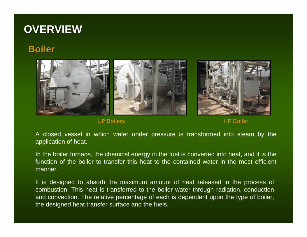
It is designed to absorb the maximum amount of heat released in the process of combustion. This heat is transferred to the boiler water through radiation, conduction and convection. The relative percentage of each is dependent upon the type of boiler, the designed heat transfer surface and the fuels.
BoilerBoiler
A closed vessel in which water under pressure is transformed into steam by the application of heat.
In the boiler furnace, the chemical energy in the fuel is converted into heat, and it is the function of the boiler to transfer this heat to the contained water in the most efficient manner.
LP BoilersLP Boilers HP BoilerHP Boiler

OVERVIEWOVERVIEW
Fire And Smoke-Tube Boiler
Firetube boilers are often characterized by their number of passes, referring to the number of times the combustion (or flue) gases flow the length of the pressure vessel as they transfer heat to the water. Each pass sends the flue gases through the tubes in the opposite direction.
The number of passes the boiler contains affects the boiler efficiency, and its first cost to manufacturer. The more heat transfer surfaces the boiler has, the more efficient it can be.
PROCESSPROCESS
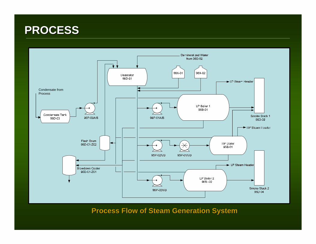
Process Flow of Steam Generation SystemProcess Flow of Steam Generation System
Condensate from Process

PROCESSPROCESS
Steam Generation System PlantSteam Generation System Plant

OPERATIONOPERATIONParameterDescription
51 pipes; ∅70 mm x 3.2 m3rd Pass
80 smoke tubes; ∅70 mm x 3.2 m2nd Pass
1 fire tube; ∅1,150 mm1st Pass
Large water space, double fire tube in 3-pass
construction cooled over a length of 5,040 mm.
Evaporator Description
3-pass combined fire & smoke-tube evaporator w/
external & cooled irradiation chamber
Type
3.9 m3 (approximate)Boiler Steam Capacity
11.9 m3 (approximate)Boiler Water Capacity
161 m2Boiler Heating Surface
91%Efficiency
148°COperating Temperature
165°C Design Temperature
3.5 barsOperating Pressure
6 barsDesign Pressure
8,000 kg/hr (Saturated Steam)
Steam Generating Capacity
Low Pressure Boiler
Low pressure steam is used for the heating-up of the jacketed vessels and pipelines in the process area.
Also, it is used for heating up the boiler feed water in the feed water deaerator up to 105OC.

OPERATIONOPERATION
High Pressure BoilerHigh Pressure Boiler
ParameterDescription
10 pipes; ∅57 mm x 3.2 m3rd Pass
16 smoke tubes; ∅57 mm x 3.2 m
2nd Pass
1 external & cooled irradiation chamber
1st Pass
Large water space, one fire tube in 3-pass construction
cooled over a length of 3,000 mm
Evaporator Description
3-pass combined fire & smoke-tube evaporator w/
external & cooled irradiation chamber
Type
0.8 m3 (approx)Boiler Steam Capacity
2.0 m3 (approx)Boiler Water Capacity
12.5 m2Boiler Heating Surface
90%Efficiency
271°COperating Temperature
276°CDesign Temperature
55 barsOperating Pressure
60 bars Design Pressure
900 kg/hr (Saturated Steam)
Steam Generating Capacity
High pressure steam is used for heating-up the barrels of the extruder and the purification columns in the purification section.

OPERATIONOPERATION
HP/LP Distribution Steam SystemHP/LP Distribution Steam System

OPERATIONOPERATION
ParameterDescription
-13 LiCapacity
58 kWHeat Output
25 m2Exchange Surface Area
394 / 200 °C105 / 159 °CDesign Temperature (In/Out)
-55 barsOperating Pressure
-60 barsMax. Allowable Pressure
Flue Gas SideWater Side
Economizer
ParameterDescription
1,250 kg/hr (approximate)Steam Consumption
50% (approximate)Condensate Percentage
50% (approximate)Fresh Water Percentage
14 tons/hrPipeline Throughput
-1/+2 barDesign Pressure
0.2 – 0.3 barOperating Pressure
150°CDesign Temperature
105°COperating Temperature
10 m3Capacity
Feed Water Deaerator Tank
Feed Water Deaerator Tank
• Removes oxygen, carbon dioxide and other noncondensable gases from feed water
• Heat-up the incoming makeup water and return condensate to an optimum temperature for
- Minimizing solubility of the undesirable gases
- Providing the highest temperature water for injection to the boiler

OPERATIONOPERATION
Condensate Tank
ParameterDescription
0.5 barDesign Pressure
0.2 – 0.3 barOperating Pressure
150°CDesign Temperature
100°COperating Temperature
7 m3Capacity
Collects condensate resulting from the process area. Steam supplied to the process area condenses after heat is given off. The steam pressure drives the condensate back to the condensate tank. An exhaust to the atmosphere maintains the tank pressure. Recycling the condensate will reduce the cost of heating feed water to the boiler and the boiler water chemicals.
Condensate TankCondensate Tank

OPERATIONOPERATION
Condensate LoopCondensate Loop

OPERATIONOPERATION
Float Trap Float Trap

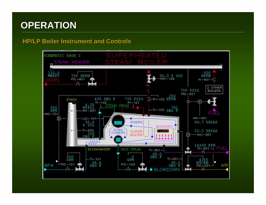
OPERATIONOPERATIONHP/LP Boiler Instrument and ControlsHP/LP Boiler Instrument and Controls
Shuts down burner if fuel gas pressure ≤ 225 mbar or ≥ 275 mbar
PZAL 31 (safety manostat)
Shuts down burner at fuel oil pressure of 2.7 barg
PZAH 33 (manostat)
Shuts down burner at fuel oil pressure of 2.3 barg
PZAL 33 (manostat)
Causes a malfunction shutdown of LP1 at 5 barg. Auto restart is not possible.
PZAH 11 (safety manostat)
SettingSafety Feature
A dedicated PLC panel cabinets for each boiler controls the operation of these steam generators.
LP Boiler ControlsLP Boiler Controls
Shuts down burner at fuel oil pressure > 1 barg.
PZAH 43 (manostat)
Causes a malfunction shutdown of LP2 at 58 barg. Auto restart is not possible.
PZAH 2 (safety manostat)
SettingSafety Feature
HP Boiler ControlsHP Boiler Controls

OPERATIONOPERATION
The following solenoid switches and level indicators control the deaerator level:
- optical level display by means of the individual magnetic flaps
- holding the preset water level constant a) When switch contact for LSL 25 is actuated
fresh demin supply pump cuts in
b) When switch contact for LSH 24 is actuated fresh demin supply pump cuts out
c) When switch contact for LSL 26 is actuated fresh condensate supply pump cuts in
d) When switch contact for LSH 27 is actuated fresh condensate supply pump cuts out
- Shuts off the boiler feed water pumps when the water level in the deaerator falls below low level
DeaeratorDeaerator Feed Water Instrument and ControlsFeed Water Instrument and Controls
Level Indicator
OPERATIONOPERATIONHP/LP Boiler Instrument and ControlsHP/LP Boiler Instrument and Controls

HP Burner
LP Burner
OPERATIONOPERATION
Fuel SystemFuel System
LPG
Propylene
Diesel
Diesel

OPERATIONOPERATION
Boiler BurnerBoiler Burner
OPERATIONOPERATION

OPERATIONOPERATION
Diesel Tank SectionDiesel Tank Section LPGLPG
Fuel SystemFuel System

OPERATIONOPERATION
LP Boiler OperationLP Boiler Operation
HP Boiler OperationHP Boiler Operation
OPERATIONOPERATION
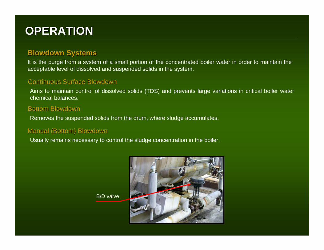
B/D valve
BlowdownBlowdown SystemsSystemsIt is the purge from a system of a small portion of the concentrated boiler water in order to maintain the acceptable level of dissolved and suspended solids in the system.
Continuous Surface Continuous Surface BlowdownBlowdownAims to maintain control of dissolved solids (TDS) and prevents large variations in critical boiler water chemical balances.
Bottom Bottom BlowdownBlowdownRemoves the suspended solids from the drum, where sludge accumulates.
Manual (Bottom) Manual (Bottom) BlowdownBlowdownUsually remains necessary to control the sludge concentration in the boiler.

OPERATIONOPERATION

OPERATIONOPERATION
BlowdownBlowdown Cooler Cooler
Collects the boiler lye periodically from the LP-steam boiler and HP-steam boiler.
Condensate will separate from the lye. Exhaust vapor will be vented to the atmosphere and the collected lye should be drained periodically to the sewage.
Flash Drum Flash Drum
Separates flash vapor from condensate in the boiler lye.
This vessel has a holding capacity of 0.024 m3 at a designed parameters of 1 bar at 280OC.

OPERATIONOPERATION
Standby Protection / PreservationStandby Protection / Preservation
Wet PreservationWet Preservation
The boiler is flooded with deaerated water due to the following:1. To eliminate the liquid-vapor interface that can cause a water line corrosion2. To prevent the condensation of acidic dropletes caused by CO2 absorption3. To eliminate any dissolved oxygen that can cause corrosion
This technique is implemented during S/Ds lasting for a month or less.
The chemical dosing for both oxygen scavenger and corrosion inhibitor uses twice the treatment volume than the normal usage to eliminate the dissolved oxygen and maintain the pH quality of 9.5–11.0. Nitrogen blanketing can also be employed to displace air from the boiler.
Dry PreservationDry Preservation
This technique is implemented for a prolonged S/Ds for more than a month.
The boiler water is drained completely. Dessicants is then added to absorb any water vapor and thus control the relative humidity in the boiler.

WATER TREATMENTWATER TREATMENTBoiler Problems Caused By WaterBoiler Problems Caused By Water
Scale forms mainly with hardness components or silica on the heating surface and the drum. Sometimes leads it leads to embrittlement and explosion of evaporation tube
• Poor water quality and fouled ion exchange resin• Incomplete control of boiler water (blow down shortage, etc)• Corrosion product brought into boiler from feed and condensate lines• Insufficient chemical injection
Cause of ProblemCause of Problem
ScaleScale

WATER TREATMENTWATER TREATMENTBoiler Problems Caused By WaterBoiler Problems Caused By Water
• Corrosion product brought into boiler from feed and condensate lines• Insufficient pH control and oxygen scavenging• Insufficient boiler water control on pH and P-alkalinity• Corrosion occurrence at shutdown or idling period
Cause of ProblemCause of Problem
Corrosion at heating surface and feed and condensate lines is due to dissolved gasses (O2, CO2) and to accumulation of metal oxides and hydrates on heating surfaces.
CorrosionCorrosion

WATER TREATMENTWATER TREATMENT
External Boiler Water TreatmentExternal Boiler Water TreatmentExternal treatment, as the term is applied to water prepared for use as boiler feed water, usually refers to the chemical and mechanical treatment of the water source. The goal is to improve the quality of this source prior to its use as boiler feed water, external to the operating boiler itself. Such external treatment normally includes:
1. Clarification2. Filtration3. Softening4. Dealkalization5. Demineralization6. Deaeration7. Heating
Feed Water Deaerator Tank
WATER TREATMENTWATER TREATMENT
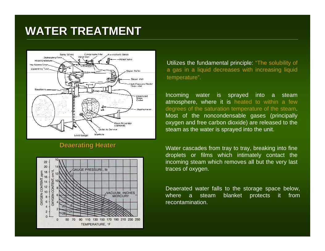
DeaeratingDeaerating HeaterHeater
Utilizes the fundamental principle: “The solubility of a gas in a liquid decreases with increasing liquid temperature”.
Incoming water is sprayed into a steam atmosphere, where it is heated to within a few degrees of the saturation temperature of the steam. Most of the noncondensable gases (principally oxygen and free carbon dioxide) are released to the steam as the water is sprayed into the unit.
Water cascades from tray to tray, breaking into fine droplets or films which intimately contact the incoming steam which removes all but the very last traces of oxygen.
Deaerated water falls to the storage space below, where a steam blanket protects it from recontamination.

WATER TREATMENTWATER TREATMENT
Internal Boiler Water TreatmentInternal Boiler Water Treatment
Oxygen Scavenger Tank Oxygen Scavenger Tank AntiscalantAntiscalant Solution Tank Solution Tank
This type of boiler compounds prevents the scale formation and adjusts the pH of boiler water to inhibit corrosion.
The phosphate-base type of antiscalant, - Reacts with hardness components Reacts with hardness components
(Ca(Ca2+2+, Mg, Mg2+2+) in) in water and converting them into water and converting them into suspendiblesuspendible substance.substance.- Keeps silica substances water soluble.Keeps silica substances water soluble.
This a chemical compound that removes dissolved oxygen in water by reduction reaction and thereby inhibits the corrosion caused by the oxygen.
- Its chemical potentiality is high enoughIts chemical potentiality is high enough to to reduce oxygenreduce oxygen- The reaction product of the scavenger and The reaction product of the scavenger and
oxygen does not have an aggressive effects on oxygen does not have an aggressive effects on the boiler or on the steams and condensate linesthe boiler or on the steams and condensate lines

WATER TREATMENTWATER TREATMENT
Typical Water Quality Control ParametersTypical Water Quality Control Parameters

WATER TREATMENTWATER TREATMENT
Raw Water Raw Water (Typical Values)(Typical Values)
≤ 105 ppm CaCO3Total Hardness
0 ppm CaCO3P Alkalinity
≤ 125 ppm CaCO3Total Alkalinity
≤ 0.1 ppm FeTotal Iron
≤ 10 ppm Cl-Chloride
≤ 3.8 ppm PO4-3Phosphate (Filtered)
≤ 14 ppm PO4-3Phosphate (Unfiltered)
≤ 150 ppm SiO2Silica
max. 265 µs/cmConductivity
7.0 (estimated)pH @ 25OC
ParameterDescription
• The raw water is considered as a ground water type of water.
0 ppm FeTotal Iron
< 0.05 ppmSilica
0 ppm CaCO3Total Hardness
< 3.0 µS/cmConductivity
< 7.0pH
ParameterDescription
DeminDemin Water QualityWater Quality

WATER TREATMENTWATER TREATMENT
0Hardness
ParameterDescription
< 2000 μS/cmConductivity
< 0.2 ppmSilica (SiO2)
< 0.003 ppmCopper
< 0.02 ppmIron
8.5 – 9.5 *pH at 25°C (LP/HP)
< 0.5 ppmOil
< 0.02 ppmO2
< 25 ppmCO2 Combined
Boiler Feed water qualityBoiler Feed water quality
* Depends on the water treatment program.
100 – 300 ppmHydrate Alkalinity
0 ppmDissolved O2
ParameterDescription
< 40 ppmSilica (SiO2)
20 - 30 ppmPhosphate (PO4-3)
< 500 μS/cmConductivity
10.4 – 11.4pH at 25°C
0 ppmDissolved O2
ParameterDescription
0 ppmHydrate Alkalinity
< 20 ppmSilica (SiO2)
10 - 20 ppmPhosphate (PO4-3)
< 300 μS/cmConductivity
LP water qualityLP water quality
HP water qualityHP water quality

Lessons LearnedLessons Learned
1. Installation of platform at the boiler stacks.1. Installation of platform at the boiler stacks.A platform was installed for sampling accessibility of flue gas. This was requested by DENR representatives in lieu of stack emission testing and permit to operate (Boilers).
2. Installation of sampling area for condensate 2. Installation of sampling area for condensate tank and boiler feed water (direct to tank and boiler feed water (direct to DeaeratingDeaeratingtank). tank).
The need to set up a new sampling points for both condensate and boiler feed water tank was for the adjustment of chemical dosing treatment and monitoring of dissolved oxygen at the boiler water lines. For the feed water, sampling is done at the bleed port of the feed water pump.

Lessons LearnedLessons Learned
3. Installation of a double pipe heat exchanger before the feed 3. Installation of a double pipe heat exchanger before the feed water pump.water pump.
A heat exchanger was installed to minimize the delta T of boiler feed water from the feed water tank to feed water pumps which can prevent the cavitation of the feed water pumps.
4. A provision for nitrogen line should be included on the desig4. A provision for nitrogen line should be included on the design for boiler n for boiler preservation.preservation.