hp superdome 2 partitioning administrator guide hp-ux 11iv3(august 2010).pdf
TRANSCRIPT

HP Superdome 2 Partitioning AdministratorGuideHP-UX 11i v3
HP Part Number: T1335-91002Published: August 2010Edition: 1.0

© Copyright 2010 Hewlett-Packard Development Company, L.P.Confidential computer software. Valid license from HP required for possession, use or copying. Consistent with FAR 12.211 and 12.212, CommercialComputer Software, Computer Software Documentation, and Technical Data for Commercial Items are licensed to the U.S. Government undervendor's standard commercial license. The information contained herein is subject to change without notice. The only warranties for HP productsand services are set forth in the express warranty statements accompanying such products and services. Nothing herein should be construed asconstituting an additional warranty. HP shall not be liable for technical or editorial errors or omissions contained herein. UNIX is a registeredtrademark of The Open Group.
Acknowledgements
Intel, Itanium, Pentium, Intel Inside, and the Intel Inside logo are trademarks or registered trademarks of Intel Corporation or its subsidiaries inthe United States and other countries.
Microsoft, Windows, Windows XP, and Windows NT are U.S. registered trademarks of Microsoft Corporation.
Adobe and Acrobat are trademarks of Adobe Systems Incorporated.
Java is a US trademark of Sun Microsystems, Inc.
Oracle is a registered US trademark of Oracle Corporation, Redwood City, California.
UNIX is a registered trademark of The Open Group.
Revision history
Publication dateEdition numberSupported versionsSupported operatingsystems
Manufacturing partnumber
August 20101.0HP-UX 11i Version v3HP-UX 11i v3T1335-91002
Table of Contents
1 Introduction...................................................................................................................11Conceptual Overview...........................................................................................................................11HP Superdome 2 terminology..............................................................................................................12
2 Partitioning in HP Superdome 2.................................................................................13Onboard Administrator and Partition Management............................................................................13Managing Partitions – Basics................................................................................................................13
nPartitions .......................................................................................................................................13Virtual Partitions (vPars).................................................................................................................14
Commands: Partition Help pages.........................................................................................................14Commands: Partition Commands Logging..........................................................................................15
Log File Location and Log Format..................................................................................................15Cases Where No Logging Occurs....................................................................................................15Cases Where Logging Occurs..........................................................................................................16Constraints and Restrictions to Logging.........................................................................................16
Ordering and Licensing........................................................................................................................16nPartitions Licensing.......................................................................................................................16Virtual Partitions Licensing.............................................................................................................16Related Software Licensing.............................................................................................................17Ordering vPars................................................................................................................................17nPartition and Virtual Partition Unique Identifiers........................................................................17
3 Getting Started with nPartitions..................................................................................19Administration Tool for nPartitions......................................................................................................19
Onboard Partition Manager............................................................................................................19Commands for Configuring nPartitions.........................................................................................19
nPartition Resources.............................................................................................................................20Assigned or Unassigned Blades and I/O bays.................................................................................21Active and Inactive Blades..............................................................................................................21I/O Enclosures and I/O Bays............................................................................................................22
Finding the Resource Path of I/O ..............................................................................................22nPartition Properties.............................................................................................................................22
Partition Names...............................................................................................................................22Partition Numbers...........................................................................................................................23Hyperthreading...............................................................................................................................23
Enabling or Disabling Hyperthreading on HP Superdome 2 using the GUI............................23Enabling or Disabling Hyperthreading on HP Superdome 2 using the CLI.............................23
Socket Local Memory......................................................................................................................23Blade Resource Attributes....................................................................................................................24Operating System Specific Default Values for nPartition Attributes...................................................25Partition State and RunStates................................................................................................................25Partition Specifications (parspec)..........................................................................................................27
Creating a Partition Specification....................................................................................................27Creating an nPartition from a Partition Specification.....................................................................27Removing a Partition Specification.................................................................................................28Saving the Current Configuration of nPartition and Switch to an Alternate Configuration..........28Viewing Partition Specification Using the OA GUI........................................................................28
Table of Contents 3

4 Planning nPartitions......................................................................................................29Recommended HP Superdome 2 nPartition Configurations...............................................................29HP Superdome 2 Partitioning Choices.................................................................................................29
Superdome 2 CPU / CPU module Support.....................................................................................31CPU Mixing Support..................................................................................................................32HP Superdome 2 Memory Support...........................................................................................32
Sample Procedure for Creating nPartitions..........................................................................................32
5 Creating and Configuring nPartitions........................................................................35Tools for Configuring nPartitions.........................................................................................................35
OA CLI.............................................................................................................................................47OA GUI............................................................................................................................................47nPartition Commands......................................................................................................................36
Commands for Configuring nPartitions....................................................................................36Granting permission for an OS to manage nPartitions........................................................................36Task Summaries for Creating and Configuring nPartitions.................................................................37Partition Default Attributes..................................................................................................................37Creating a New nPartition....................................................................................................................38
Creating a New nPartition Using the OA CLI.................................................................................38Creating a New nPartition Using the OA GUI................................................................................38
Verifying Newly Created nPartitions...................................................................................................38Removing (Deleting) an nPartition.......................................................................................................40
Removing (Deleting) an nPartition Using the OA CLI...................................................................40Removing (Deleting) an nPartition Using the OA GUI..................................................................40
Renaming an nPartition........................................................................................................................40Renaming an nPartition Using the OA CLI.....................................................................................40Renaming an nPartition Using the OA GUI....................................................................................40
Assigning (Adding) Blades and I/O Bays to an nPartition...................................................................41Assigning (Adding) Blades and I/O Bays to an nPartition Using the OA CLI...............................41Assigning (Adding) Blades and I/O Bays to an nPartition Using the OA GUI..............................41
Unassigning (Removing) Blades and I/O Bays from an nPartition......................................................42Unassigning (Removing) Blades and I/O Bays from an nPartition Using the OA CLI..................42Unassigning (Removing) Blades and I/O Bays from an nPartition Using the OA GUI..................42
Renaming a Server Complex................................................................................................................44Setting Blade Attributes........................................................................................................................44
Setting Blade Attributes Using the OA CLI....................................................................................44Setting Blade Attributes Using the OA GUI....................................................................................44
6 Booting and Resetting Partitions (nPartitions and vPars)..........................................47Overview of Partition System Booting.................................................................................................47Accessing the OA..................................................................................................................................47
OA CLI.............................................................................................................................................47OA GUI............................................................................................................................................47
Booting to EFI and Preparing for Operating System Installation........................................................48Booting from the CLI ......................................................................................................................48Booting from the GUI......................................................................................................................50Getting a Console Using the CLI.....................................................................................................51Getting a Console Using the GUI....................................................................................................52Confirming the Installed IO cards...................................................................................................52Getting MAC Addresses for Ignite-UX...........................................................................................54
Task Summaries for Rebooting and Resetting Partitions.....................................................................54POWEROFF PARTITION................................................................................................................55POWERON PARTITION.................................................................................................................58
4 Table of Contents

REBOOT PARTITION.....................................................................................................................59SET PARTITION DVD.....................................................................................................................59SHOW PARTITION DVD................................................................................................................62SHOW PARTITION INFO...............................................................................................................63Force System Reset and Crash Dump (TOC) PARTITION.............................................................63UPDATE NPARTITION..................................................................................................................65UPDATE SHOW NPARTITION......................................................................................................66UPDATE FIRMWARE......................................................................................................................66UPDATE SHOW FIRMWARE.........................................................................................................66
HP Superdome 2 Boot Support.............................................................................................................67Local Boot........................................................................................................................................67
Considerations for Local Boot....................................................................................................68Boot from local SAN...................................................................................................................68Boot from External SAN.............................................................................................................68
nPartition and Resource Health Status.................................................................................................68Viewing Partition and Resource Health Status Using the CLI........................................................69Viewing Partition and Resource Health Status Using the OA GUI................................................70Resource health policy ....................................................................................................................71
7 Planning Your System for Virtual Partitions................................................................73Planning Your Virtual Partitions...........................................................................................................73
Virtual Partitions Layout Plan.........................................................................................................73Virtual Partition Names...................................................................................................................73Minimal Hardware Configuration..................................................................................................73CPU-core..........................................................................................................................................74
CPU-core: Boot Processor Definitions .......................................................................................74CPU-core: Specifying Min and Max Limits...............................................................................74CPU-core: Adding and Deleting by Total..................................................................................74
vparcreate..............................................................................................................................75vparmodify...........................................................................................................................75
CPU-core: Adding or Deleting by SLP (Socket Local Processor)..............................................76CPU-core: Adding or Deleting by Resource path......................................................................76CPU: Summary Information......................................................................................................76Deleting CPU-cores Summary...................................................................................................77CPU Allocation...........................................................................................................................77
Memory...........................................................................................................................................77Assigning Memory to a vPar......................................................................................................78
I/O....................................................................................................................................................78Assigning I/O at the rootport or I/O slot Level..........................................................................78
Syntax, Rules, and Notes.................................................................................................................79Counts Summary........................................................................................................................80
Parspec change policy......................................................................................................................80A note on Deconfiguration..............................................................................................................80
8 Managing and Booting Virtual Partitions..................................................................83Modes: Switching between nPars and vPars Modes .......................................................................83
Modes..............................................................................................................................................83Setting the Mode..............................................................................................................................84
Getting the vPar Console ...........................................................................................................85Managing: Creating a Virtual Partition................................................................................................86Booting a Virtual Partition....................................................................................................................86Managing: Modifying Attributes of a Virtual Partition........................................................................86Commands: Displaying vPars Resource Information (vparstatus)......................................................87
Table of Contents 5

Virtual Partition States.....................................................................................................................87vparstatus: Summary Information..................................................................................................89
Shutting Down or Rebooting a Virtual Partition..................................................................................90Shutting Down All Virtual Partitions..............................................................................................92
Managing: Removing a Virtual Partition..............................................................................................92Boot options management for partitions..............................................................................................92
9 Installing or Removing the vPars.................................................................................95Notes Before You Install vPars Software..............................................................................................95
Notes................................................................................................................................................95Installing vPars......................................................................................................................................95Bundle Names.......................................................................................................................................96
vPars Product Bundles....................................................................................................................96Ignite-UX Cookbook.............................................................................................................................96Removing the vPars Product................................................................................................................96
10 Support and other resources.....................................................................................97Contacting HP ......................................................................................................................................97
Before you contact HP.....................................................................................................................97HP contact information...................................................................................................................97Subscription service.........................................................................................................................97Documentation feedback.................................................................................................................97
Related information..............................................................................................................................97Typographic conventions......................................................................................................................98
A Partition commands...................................................................................................101
Glossary.........................................................................................................................103
Index...............................................................................................................................105
6 Table of Contents

List of Figures3-1 nPartition Status Information........................................................................................................263-2 Viewing Partitition Specification Information..............................................................................284-1 Partition Rules — 16s.....................................................................................................................304-2 Partition Rules — 8s......................................................................................................................315-1 OA GUI Login Screen....................................................................................................................485-2 Modify nPartition Window...........................................................................................................385-3 Blade Resources Option................................................................................................................415-4 IOX Resources Option...................................................................................................................425-5 Blade Resources Option................................................................................................................435-6 IOX Resources Option...................................................................................................................435-7 Blade Attributes section................................................................................................................445-8 Memory Settings............................................................................................................................456-1 OA GUI Login Screen....................................................................................................................486-2 nPartition Status Information........................................................................................................506-3 vPar Status information.................................................................................................................506-4 nPartition Virtual Devices tab.......................................................................................................506-5 vPar Virtual Devices tab................................................................................................................516-6 Active/vPars Mode State of an nPartition.....................................................................................516-7 Active/EFI prompt State of vPar....................................................................................................516-8 Remote Console Tab (nPar)...........................................................................................................526-9 Remote Console Tab (vPar)...........................................................................................................526-10 Status Information of an nPartition ..............................................................................................566-11 Status Information of a vPar .........................................................................................................576-12 Graceful and Force Poweroff (nPartition).....................................................................................576-13 Graceful and Force Poweroff (vPar)..............................................................................................586-14 SET Partition DVD for an nPartition.............................................................................................606-15 SET Partition DVD for vPar...........................................................................................................616-16 Virtual Media Screen.....................................................................................................................616-17 SHOW Partition DVD for an nPartition........................................................................................626-18 SHOW Partition DVD for vPar......................................................................................................636-19 TOC nPartition..............................................................................................................................646-20 TOC vPar.......................................................................................................................................646-21 Firmware Summary Information..................................................................................................666-22 Firmware Summary.......................................................................................................................676-23 nPartition Health Status................................................................................................................718-1 Virtual Device................................................................................................................................858-2 Remote Console.............................................................................................................................85
7

List of Tables1-1 HP Superdome 2 terminology.......................................................................................................123-1 nPartition Commands Descriptions............................................................................................1013-2 RunStates for nPartition................................................................................................................264-1 Superdome 2 supported CPU Matrix............................................................................................315-1 nPartition Commands Descriptions..............................................................................................365-2 nPartition Boot and Reset Task Summaries...................................................................................376-1 nPartition Boot and Reset Task Summaries...................................................................................547-1 CPU-core Allocation......................................................................................................................777-2 Assigning I/O Resources...............................................................................................................797-3 Resource syntax summary............................................................................................................808-1 Run-states of an inactive Virtual Partition....................................................................................878-2 Run-states of an active Virtual Partition.......................................................................................8810-1 Documentation and its location....................................................................................................98A-1 Partition Commands Descriptions..............................................................................................101
8 List of Tables

List of Examples2-1 Unique IDs for an nPartition and Complex..................................................................................182-2 Unique IDs for Virtual Partitions (vPars)......................................................................................188-1 Booting a vPar...............................................................................................................................848-2 Example.........................................................................................................................................85
9

10

1 IntroductionThe HP Integrity Superdome 2 servers (HP Superdome 2) are scalable systems based on bladesystem architecture. HP Superdome 2 systems support HP nPartitions and HP-UX VirtualPartitions (vPars). This administrator guide describes the steps to plan, create, and managepartitions – nPartitions and virtual partitions – on an HP Superdome 2 system.This guide is primarily for users who have prior experience in managing nPartitions and virtualpartitions on HP servers.
Conceptual OverviewHP Superdome 2 Onboard Administrator (OA) is the complex management processor, subsystem,and firmware base used to support HP Superdome 2 complexes and all the managed devicescontained within the complex.The Onboard Administrator provides a single point from which to perform basic managementtasks on compute enclosures, server blades, IO expansion enclosures or IO interconnects withinthe complex. Onboard Administrator helps perform configuration steps for the complex, enablesrun-time management and configuration of the complex components, and informs you of problemswithin the complex through email, SNMP, or the Insight Display.For information on setting up the Onboard Administrator, see the the specific HP Superdome 2User Service Guide.The following figure depicts the different ways you can interact with the system to managepartitions. There are primarily three ways you can do partition management on HP Superdome2 systems.
Conceptual Overview 11

• From the OA. OA Graphical User Interface (GUI) and Command Line Interface (CLI) supportpartition management user interfaces.
NOTE: The initial release of HP Superdome 2 does not support iCAP CLIs on the OA.
• From the partitions. Operating system based (Legacy) partition management commandinterfaces are still supported from the partition side.
• From a Central Management System (CMS). HP Systems Insight Manager (HP SIM) andother plug-ins from the CMS can be used to manage partitions.
HP Superdome 2 terminologyTable 1-1 “HP Superdome 2 terminology” describes terms specific to HP Superdome 2.
Table 1-1 HP Superdome 2 terminology
DescriptionTerm
On HP Superdome 2 platforms, resources in the complex areidentified by a resource path. The Resource Path describes physicalhardware resources in a hierarchy of elements called entity. Eachresource path consists of a hierarchical list of entity numbers. Thehierarchy describes parent-child relationships. The parent is listedto the left of the child. Each entity number is relative to the parent.The separator between the entity numbers is the slash (/) character.For more information on resource path, see help resourcepath. Forexample, the resource path 1/1 identifies blade 1 in enclosure 1 ofa HP Superdome 2 complex.
Resource path
LoMs represent the network ports on the blade.LAN on Motherboards (LoMs)
This is the active instance of the Onboard Administrator.Monarch OA
Platforms that have Onboard Administrator (OA) based partitionmanagement support partition specifications or parspecs. A parspecis a collection of data that defines the configuration of a specificnPartition, including the virtual partitions in the nPartition if thecustomer has defined any virtual partitions. For more informationon partition specifications, see “Partition Specifications (parspec)”
Partition specifications (parspecs)
The Onboard Administrator instance which can take over the roleof the Active or Monarch OA in the event of a failure of the MonarchOA.
Standby/Redundant OA
A socket on HP Superdome 2 represents the Field Replacableprocessing unit on a blade. Each socket presents 4 CPU-cores.
Socket
A unit that contains CPU-cores, memory and onboard NetworkInterface cards (NICs). A blade is the equivalent of a cell (incell-based platforms) in terms of being the unit of assignment fordefining nPartitions.
Blades
A unit that can be added to an HP Superdome 2 complex to add I/Oslots to the complex. An IOX provides upto 12 PCIe slots.
IOX / I/O Bay
The unit that hosts either a blade or an IO Bay in an HP Superdome2 complex.
Enclosure
12 Introduction

2 Partitioning in HP Superdome 2Onboard Administrator and Partition Management
This chapter provides information on managing partitions – hard partitions (nPartitions) andvirtual partitions (vPars) – using the Onboard Administrator.The OA supports both a graphical user interface (GUI) as well as a command-line user interface(CLI). You can log in to the OA GUI by entering the appropriate URL in the web browser. TheURL must include the hostname or IP address of the OA. Partitions on HP Superdome 2 systemssupport HP-UX 11i v3 operating environments.The OA GUI enables you to manage nPartitions and vPars. The OA GUI runs on OA hardware,and gives you the ability to completely manage an HP Superdome 2 system, including managingnPartitions and vPars, from a single interface. The OA GUI replaces the Partition Managerapplication in the legacy superdome.For detailed information about using the OA GUI, see the HP Superdome 2 Onboard AdministratorUser Guide, and for detailed information about using the OA CLI, see theHPSuperdome 2OnboardAdministrator Command Line Interface User Guide.
Managing Partitions – BasicsThe partition management architecture on HP Superdome 2 is designed to adapt to the newhardware and firmware architecture. Partitioning (both nPartitions and vPars) is implementedin the firmware and the OA-based architecture supports a unified nPartition and virtual partitionmanagement. The core of partition management functionality now resides on the managementprocessor or onboard administrator (OA).The OA-based partition management architecture on HP Superdome 2 systems supports integratednPartition and virtual partitioning. nPartitions can be further subdivided using virtual partitions.You interact with both partition types in the same way. User interfaces for routine operationssuch as boot, shutdown, and reset are common across vPars and nPartitions, and are availablefrom both of the OA user interfaces. Each virtual partition has a separate console and presentsan EFI shell just like an nPartition. OS install operations and OS boot methods for an nPartitionand a virtual partition are the same.A partition is identified by its unique number and name. The range of partition numbers fornPartitions is 1 to 255, and the range of partition numbers for virtual partitions is 1 to 255. Partitionnumbers cannot be modified while the name can be changed. nPartition names must be uniquewithin a complex, and virtual partition names must be unique within an nPartition. BothnPartitions and virtual partitions have a state and a run-state. The states is one of 'active' or'inactive'. The various run-states that an nPartition or vPar can be in are described in a laterchapter.
nPartitionsAn nPartition is a hard partition that contains one or more blades and zero or more I/O bays.nPartitions can run a single OS (either a standalone OS or an HPVM host), or can be divided intovirtual partitions. An nPartition on HP Superdome 2 system is similar to an nPartition on cellbased servers. On HP Superdome 2, it is possible to create an nPartition without assigning anyresources (no blade or I/O bay resources assigned). However, such an nPartition will need to beassigned resources before it can be activated or powered on for use. An nPartition provideselectrical isolation.You can use the OA to perform the following nPartition functions:• Create a new nPartition.• Modify an existing nPartition.
Onboard Administrator and Partition Management 13

• Boot an existing nPartition.• Remove an nPartition.• Rename an nPartition.• Reset an nPartition.• Assign and unassign resources such as blades and I/O bays.You can define many possible configurations for an nPartition complex, and then control whichconfigurations or which partitions will exist at any given point in time. This is possible by usingpartition specifications. A partition specification is a mechanism you can use to store the definitionof a partition. This is like a 'plan' for the nPartition, and contains your inputs regarding thedefinition of a nPartition including the definition of any and all virtual partitions that are in it.An nPartition can have more than one specification: that is, multiple partition specifications canbe associated with the same partition number. This gives you the ability to create and savemultiple definitions for any nPartition. You can create, modify, remove, copy, rename, and listthe partition specifications.
NOTE: All of the partition commands are also available from HP-UX running in a partition.
Virtual Partitions (vPars)A virtual partition is a fine grained firmware subset of a hard partition (nPartition) where eachvirtual partition can run an independent instance of HP-UX. An nPartition can contain a maximumof 16 virtual partitions. You can assign the resources available in the nPartition to the virtualpartitions. In HP Superdome 2 systems, you can assign CPU cores, memory (interleaved (ILM)and socket local (SLM)), and I/O.You can use the OA to perform the following functions related to virtual partitions:• Create a new vPar.• Modify an existing vPar.• Boot an existing vPar.• Remove a vPar.• Rename a vPar.• Reset a vPar.• Assign and un-assign resources such as memory, CPU, and I/O.The OA supports the following virtual partition commands – vparcreate, vparmodify, vparremove,vparboot, vparreset, and vparstatus.For information about the new partition features in HP Superdome 2 and to learn the differencesbetween implementation of partitioning in HP Superdome 2 and in the older systems, see thetechnical white paper New Features in Superdome 2 Partition Management.
Commands: Partition Help pagesThe purpose of Partition Help pages is to describe Partition concepts and how to perform commonPartition tasks. For detailed information on the Partition commands, including description,syntax, all the command line options, and the required state of a partition for each command,see the Partition help pages.On the OA, use the help command to access the help pages. For example, at the OA prompt, runhelp vparcreate2 to display the help text for vparcreate. On the OS, use the man commandto display the corresponding manpage. For example, run man vparcreate to display thevparcreate manpage.
14 Partitioning in HP Superdome 2

Note the following on Partition help pages:— You can run the help command to see the current list of Partition help pages.— As of this printing, the Partition help pages are:
◦ nPartition Commandsparcreate, ,parmodify, pardefault, parremove, parstatus, and parperm
◦ vPartition Commandsvparcreate, , vparmodify, vparreset, vparremove, vparstatus, and vecheck
Commands: Partition Commands LoggingOn the OA, the Partition commands executed are logged into the OA syslog file. The contentsof the OA syslog file is displayed by show syslog OA at the OA prompt. On the OS side, thePartition commands executed from the HP-UX shell are logged to the local syslog file (the syslogfile of the partition from which the partition command was executed).
Log File Location and Log FormatThe default syslog file on HP-UX systems is/var/adm/syslog/syslog.log.The format of the log entries isdate hostname vPars_command_name[pid]: user username:vPars_command_line_text
date hostname vPars_command_name[pid]: exit status exit_status
where• vPars_command_name is the name of the vPars command which is sending messages to
syslog.• username is the name returned by getlogin(). If no username is given by getlogin(),
the effective username or id will be used.• vPars_command_line_text is the vPars command line text as typed by the user.• pid is the pid (Process ID) of the command invocation. The PIDs shown will be the same
for both the command invocation syslog entry and the exit status syslog entry. Thisallows matching the exit status with its corresponding command invocation.
Below are examples of vPars syslog entries.Oct 29 19:47:47 Oslo2 vparmodify[2962]: user root: /sbin/vparmodify -pOslo3 -a cpu::1
Oct 29 19:47:47 Oslo2 vparmodify[2962]: exit status 1
Cases Where No Logging OccursOn the OA, the syslog file contents is accessed by show syslog OA from the OA prompt.Below are the cases where logging does not occur (and no changes are made):• a non-root user in an OS attempting a Partition command• syntax, usage, or other Partition commands errors• Commands which do not affect the state of the other partitions such as parstatus,
vparstatus and vecheck.
Commands: Partition Commands Logging 15

Cases Where Logging OccursBelow are the cases where logging does occur:• Commands which change and/or affect the state of partitions.
These commands includeparcreate,parmodify,parremove,vparboot,vparcreate,vparenv, vparremove, vparmodify, and vparreset.
Constraints and Restrictions to LoggingNote the following:• The command line text will be logged on only the partition from which the command was
executed. The logging of the command will not be duplicated to the target syslog file (thesyslog file of the target partition.For example, if thevparmodify command is executed fromvPar1with the target partitionbeing vPar2 (vparmodify -p vPar2 ...), the syslog entries will only appear in thelog file of vPar1. Nothing will appear in the log file of vPar2.
• The command line text for partition commands executed from the OS is not duplicated inthe syslog of the OA. The OA syslog reflects only the commands run from OA. The OS syslogreflects only commands run from the OS.
• Error messages from the failure of a partition command execution are not logged.
Ordering and LicensingThis section describes the ordering and licensing of the HP-UX Virtual Partitions software itself,as well as software that runs within the vPars (the HP-UX 11i Operating Environment, and theHP-UX 11i application software).
nPartitions LicensingnPartitions does not require any licensing.When you license a software product to run on an HP server, you may need to provide machineor system details to the software vendor as part of the software registration process.This section describes how to obtain information you may need when licensing non-HP softwareto run on an HP Superdome 2 server.For complete information about software product licensing, refer to the company thatmanufactures or sells the software you plan to use.
Virtual Partitions LicensingOn HP Integrity Superdome 2 servers, the HP-UX Virtual Partitions (vPars) product whichenables managing vPars from HP-UX is sold on a per-socket licensing basis. Therefore, youpurchase the same quantity of this product as the number of active sockets in your nPartitions(or non-nPartitioned server) that will be running vPars. If you later purchase additional processingsockets, you must also purchase the corresponding number of per-socket licenses of vPars.You can purchase vPars:1. As part of the HP-UX 11i v3 Virtual Server environment-OE (VSE-OE)2. As part of the HP-UX 11i v3 Data Center-OE (DC-OE)3. As part of the Insight Dynamics – VSE Suite4. Or stand-alone, as T1335DC (software product bundle)
16 Partitioning in HP Superdome 2

NOTE: HP Integrity servers running the new HP sx3000 chipset are quad core (4 cores perprocessor/ per socket), but HP-UX licensing is per-socket or per processor. Therefore, oneper-socket software license is required per each quad-core processor. The processor and socket,both represent a processing unit, and presents 4 cores on it.
Though vPars can be created from the OA without purchasing a vPar license, HP does not supportsuch configurations. Attempting to boot HP-UX in a vPar without purchasing a vPar license cancause unpredictable behavior and should be avoided.
Related Software LicensingCustomers have two options for purchasing HP-UX OS or application software that runs withinvPars: Per nPartition Licensing, or HP-UX 11i Software Virtualization Licensing.1. Per nPartition Licensing: allows licensing of HP-UX 11i software to be based on the number
of active processors in the server or nPartition.2. HP-UX 11i Software Virtualization Licensing: allows customers to purchase software
licenses for the maximum number of sockets that software is planned/configured to be runon.
For more information on HP-UX software licensing, including Virtualization Licensing for HP-UX,see: http://h71028.www7.hp.com/enterprise/us/en/os/hpux11i-oe-software-licensing.html?jumpid=reg_R1002_USEN
Ordering vParsWhile vPars is available as a standalone layered product, it is highly recommended that it bepurchased as part of the VSE-OE (Virtual Server Environment OE) or the DC-OE (Data CenterOE). The OEs provide the highest level of integration, robust management and ease of use foran HP-UX virtualized environment, as well as offering substantial cost-savings over buyingindividual layered products. vPars is also available as part of the Insight Dynamics Virtual ServerEnvironment for Integrity.
nPartition and Virtual Partition Unique Identifiers• Unique Machine (Complex) Identifier /usr/bin/getconf _CS_MACHINE_IDENT
• Unique nPartition Identifier /usr/bin/getconf _CS_PARTITION_IDENT
• Unique Virtual Partition Identifier /usr/bin/getconf _CS_PARTITION_IDENT
• Machine (Complex) Serial Number /usr/bin/getconf _CS_MACHINE_SERIAL and/usr/sbin/parstatus -X
• Server (Complex) Product Number /usr/sbin/parstatus -X
• Machine (Complex) Hardware Model /usr/bin/getconf MACHINE_MODEL and/usr/bin/model
• HP-UX Version and Installed BundlesFor the HP-UX version: /usr/bin/uname -rFor all bundles installed: /usr/sbin/swlist -l bundle
NOTE: Use the getconf command or the confstr() call to obtain unique identifiers. Do notuse the uname -i command, which does not report unique IDs for nPartition systems.
In order to guarantee compatibility on current and future platforms, use the interfaces to getconf(1)and confstr(3C) to retrieve unique machine identifiers. These interfaces and the commands listedbelow are available from the HP-UX operating system running in the nPartition or vPar.
Ordering and Licensing 17

The interfaces include the _CS_PARTITION_IDENT and _CS_MACHINE_IDENT parameters:• For a nPartition-specific or a virtual partition-specific unique ID use this command:
/usr/bin/getconf _CS_PARTITION_IDENT
The unique partition identifier value for a virtual partition environment has virtualpartition-specific data added that does not appear for an equivalent non-vPars environment.See the examples that follow.
• For a complex-specific unique ID use this command:/usr/bin/getconf _CS_MACHINE_IDENT
Example 2-1 Unique IDs for an nPartition and Complex
The following examples show nPartition-unique and complex-unique IDs returned by thegetconf command, as well as the local nPartition number and machine serial number.# parstatus -wThe local partition number is 1. # /usr/bin/getconf _CS_PARTITION_IDENTZ3e02955673f9f7c9_P1# /usr/bin/getconf _CS_MACHINE_IDENTZ3e02955673f9f7c9# /usr/bin/getconf _CS_MACHINE_SERIALUSR2024FP1#
Example 2-2 Unique IDs for Virtual Partitions (vPars)
The following example shows the virtual partition-unique ID returned by thegetconf command,as well as the local nPartition number and the current virtual partition name.# parstatus -wThe local partition number is 0. # vparstatus -wThe current virtual partition is Shad.# getconf _CS_PARTITION_IDENTZ3e0ec8e078cd3c7b_P0_V00#
For details on virtual partitions, see Chapter 9 “Installing or Removing the vPars”.
18 Partitioning in HP Superdome 2

3 Getting Started with nPartitionsHP Superdome 2 with sx3000 processors uses c-Class technology for the architecture of thesystem. The management of Superdome 2 is done by an Onboard Administrator (OA) withenhanced firmware. This Onboard Administrator has partitioning capabilities, both for hardpartitions (nPartition) and for virtual partitions (vPar) . You can manage the nPartitions andvirtual partitions through the OA without the need to install software on any disk. Partitionscan also be managed from the OS's in the partitions (nPartition or vPar). The same set ofcommands as in legacy servers can be used for partition management on HP Superdome 2 servers.This chapter addresses the following topics:• “Administration Tool for nPartitions”• “nPartition Resources”• “nPartition Properties”• “Blade Resource Attributes”• “Operating System Specific Default Values for nPartition Attributes”• “Partition State and RunStates”• “Partition Specifications (parspec)”
Administration Tool for nPartitionsThe administration tool for nPartitions is the OA, which provides a graphical user interface anda command-line interface. This section discusses the following topics:• “Onboard Partition Manager”• “Commands for Configuring nPartitions”
Onboard Partition ManagerThe Onboard Partition Manager is a set of tools integrated with the HP Superdome 2 OnboardAdministrator. The tools in the Onboard Partition Manager allow you to configure both nPartitionsand virtual partitions. These tools replace the legacy tools for partition configuration (ParMgrfor nPartitions and vparmgr for virtual partitions). The Onboard Partition Manager tools providemany enhancements over the previous tools The OA GUI can be launched either directly fromthe OA or from an operating system instance via the HP System Management Homepage (SMH).
Commands for Configuring nPartitionsYou can use the nPartition commands within an instance of HP-UX to create, modify, monitor,and remove nPartitions (with the exception of parperm, which is available only from the OA).Table 3-1 describes the nPartition configuration commands.
NOTE: To execute partition commands from the operating system, root access is required.
For more information on the nPartition commands, see the nPartition command help.
Table 3-1 nPartition Commands Descriptions
DescriptionCommand
Create a new nPartition.parcreate
Display or change default values of certain nPartition attributes.pardefault
Modify an existing nPartition.parmodify
Administration Tool for nPartitions 19

Table 3-1 nPartition Commands Descriptions (continued)
DescriptionCommand
Configure partition configuration privilege for nPartitions and vPars.
NOTE: This command is available only from the OA.
parperm
Remove an existing nPartition.parremove
Display nPartition information and hardware details for a server complex.parstatus
nPartition ResourcesOn an HP Superdome 2 system, you can create or manage nPartitions, assigning them thefollowing resources:• Blade A blade consists of CPUs, memory, blade I/O (which includes LAN on Motherboard
(LOM) modules and iLO).
• I/O Bay An I/O Bay consists of six PCIe slots.
You can view the number of resources on HP Superdome 2 using the parstatus command inthe OA CLI. A sample parstatus command output is as shown below:parstatusNOTE: No action specified. Default behavior is display all.
[Complex]
Complex Name: Complex1Complex UUID: FFFFFFFF-FFFF-FFFF-FFFF-FFFFFFFFFFFFComplex Capacity Compute Enclosure: 1 IO Enclosure: 8Monarch OA Location: 1Model: N/AOriginal Serial Number: UnsetCurrent Product Order Number: AH337AOEM Manufacturer: N/ATotal number of partitions present: 0
[Enclosure]
Enclosure Enclosure Num Num Bay EnclosureNum Type Blades IOBays Slots Name========= ========= ====== ====== ===== =========1 Compute 8 0 8 stanley5 IO 0 2 2 -6 IO 0 2 2 -7 IO 0 2 2 -8 IO 0 2 2 -9 IO 0 2 2 -10 IO 0 2 2 -11 IO 0 2 2 -12 IO 0 2 2 -
[Blade]
Enclosure/ Usage/ CPU Memory Use Par PendingBlade Status* OK/ (GB) On Num Deletion Indicted/ OK/ Next Deconf/ Indicted/ Boot Max Deconf========== ======================= ========= =============== ==== === ========1/1 Inactive Base /OK 8/0/0/8 128.0/0.0/0.0 - - -1/2 Inactive Base /OK 8/0/0/8 128.0/0.0/0.0 - - -1/3 Inactive Base /OK 8/0/0/8 128.0/0.0/0.0 - - -
20 Getting Started with nPartitions

1/4 Inactive Base /OK 8/0/0/8 128.0/0.0/0.0 - - -1/5 Inactive Base /OK 8/0/0/8 128.0/0.0/0.0 - - -1/6 Inactive Base /OK 8/0/0/8 128.0/0.0/0.0 - - -1/7 Inactive Base /OK 8/0/0/8 128.0/0.0/0.0 - - -1/8 Inactive Base /OK 8/0/0/8 128.0/0.0/0.0 - - -
* D-Deconfigured I-Indicted
[IOBay]
Enclosure/ Usage/ Par PendingIOBay Status* Num Deletion========== ======================= === ========5/1 Inactive /OK - -5/2 Inactive /OK - -6/1 Inactive /OK - -6/2 Inactive /OK - -7/1 Inactive /OK - -7/2 Inactive /OK - -8/1 Inactive /OK - -8/2 Inactive /OK - -9/1 Empty /Invalid - -9/2 Empty /Invalid - -10/1 Empty /Invalid - -10/2 Empty /Invalid - -11/1 Empty /Invalid - -11/2 Empty /Invalid - -12/1 Empty /Invalid - -12/2 Empty /Invalid - -
* D-Deconfigured I-Indicted
[Partition]
Par State/ Status* # of # of ILM/ Partition NameNum RunState Blades IOBays SLM (first 15 (GB)** characters)=== ======================= ======= ====== ====== ============= ===============
* D-Degraded** Actual allocated for Active and User requested for Inactive partitions
In addition to providing the resource information, the parstatus command also shows theexisting nPartitions if any.
Assigned or Unassigned Blades and I/O baysEach blade in a server complex is either assigned to one of the nPartitions in the complex, orunassigned. If an I/O bay is unassigned, it is not used by any nPartition. Blades and I/O baysthat are unassigned are considered to be available resources; they are free to be assigned to anyof the existing nPartitions, or can be used to create new nPartitions.You can assign a blade to an nPartition or unassign a blade from the nPartition by using theparcreate or the parmodify commands. For more information, see help parcreate andhelp parmodify.
Active and Inactive BladesBlades that are assigned to an nPartition and have been booted are active blades whose resources(processors, memory, and on-board I/O) can be actively used by software running in the nPartition.Blades that are Inactive are either not assigned to an nPartition (recognized by the empty "ParNum" field against those blades in the parstatus command output) or are assigned to annPartition that is not yet powered on (partition statusInactive/DOWN in parstatus commandoutput). Blades assigned to an nPartition are powered only when the partition to which they areassigned are powered on or activated. A blade may show up as Inactive while being part of
nPartition Resources 21

an nPartition that has been powered on, or if the user has set the use_on_next_boot attributeof the blade to be false.
I/O Enclosures and I/O BaysHP Superdome 2 I/O Expansion Enclosures (IOX enclosures) contain two bays, each of whichmay be independently assigned to nPartitions. I/O bays are not directly attached to blades onHP Superdome 2 servers - the I/O bays in an IOX have to be assigned to specific partitions, thusallowing more flexibile I/O assignments. Therefore, in addition to blades, every nPartition canhave I/O explicitly assigned to it. The resource path format for specifying an I/O bay isIO_enclosure#/iobay#. I/O bays are assigned using the -aio:enclosure#/iobay#:[use_on_next_boot] option of theparcreate andparmodifycommands.
NOTE: There are some I/O slots on the blade itself. These are two dual-port LAN on Motherboardmodules (LoMs), 3 mezzanine card slots, and the blade's iLO port. The mezzanine slots areassigned the slot numbers 1, 2, and 3. The LoMs are assigned the slot numbers 4 and 5. The iLOis assigned slot number 6.The mezzanine cards are not supported at the first release. If the I/Oon the blade is not sufficient for the nPartition, additional I/O may be assigned by using the IOXexpansion enclosure.
Finding the Resource Path of I/OThe resource path of your blade-based I/O components and I/O bay based I/O slots can be foundthrough the OA CLI or through EFI commands. Using the HP Superdome 2 OA, the commandparstatus –c {enclosure#/blade#} –V. For example,parstatus -c1/2 -V commandreports the path of the LoMs on blade 2 in enclosure 1. Using EFI, the info io command returnsthe results of all resources paths to all I/O. Following is a sample output of the info io commandfor a dual ported LoM (enclosure 1, blade 2, I/O slot 5) 1/2/5 04/80 00/00 14E4/1650 103C/7105/00 Network Controller - Ethernet control 1/2/5 04/80 00/01 14E4/1650 103C/7105/00 Network Controller - Ethernet control
For the same LoMs the resource path listing using the parstatus -c1/2 is shown below. LANon Motherboard NICs are numbered 4 and 5, as shown below:
RP Path Slot Slot Type Status=========== ========= ========== =======1/2/0/0/0 1/2/4 Lan OK1/2/0/0/2 1/2/5 Lan OK
nPartition PropertiesThis section describes the commonly used nPartition properties you work with when performingnPartition administration tasks.The following nPartitions details are covered here:• “Partition Names”• “Partition Numbers”• “Hyperthreading”• “Socket Local Memory”
Partition NamesSpecifies the name of the nPartition. The parcreate —P name command is used to create annPartition with a name associated to it. An nPartition name must have at least one of the followingnon-numeric characters: a-z, A-Z, dash (-), under-score (_), or period (.). No other non-numericcharacter is allowed in an nPartition name. An nPartition name with the same format as thedefault name can only be specified if the specified name matches the nPar number. If name is
22 Getting Started with nPartitions

not specified either through the -p or -P options, a default name of the format nParnnnn isgiven to the nPartition (where nnnn is a 4 digit nPartition number).
Partition NumbersSpecifies the number of the nPartition. The parcreate —p number command is used to createan nPartition with a number associated to it. If -p number is not specified, an nPartition numberis automatically assigned to the created nPartition. Valid partition numbers range from 1-255.
HyperthreadingHyperthreading technology delivers thread-level parallelism on each processor core resultingin more efficient use of processor resources—higher processing throughput and improvedperformance on multi-threaded software. Hyperthreading is enabled by default in an nPartitionrunning on HP Superdome 2 servers.
NOTE: Hyperthreading was not enabled by default on legacy systems.
Enabling or Disabling Hyperthreading on HP Superdome 2 using the GUITo enable or disable hyperthreading on HP Superdome 2 using the GUI, complete the followingsteps:1. Log into the OA GUI.2. Select the nPartition in the System and Devices tab.3. Click Modify nPartition.4. Click Advanced Settings.5. Check or uncheck the Enable Hyperthreading.6. Click Apply.Hyperthreading is enabled or disabled depending on whether you check or uncheck the EnableHyperthreading option.
Enabling or Disabling Hyperthreading on HP Superdome 2 using the CLITo enable hyperthreading on HP Superdome 2, run the following command:parmodify -p <nParId> -T y
To disable hyperthreading on HP Superdome 2, run the following command:parmodify -p <nParId> -T n
nParId can either be the nPar name or the nPar number.
NOTE: Once hyperthreading is enabled for an nPartition, it is still necessary to configure thatpartition's operating system to use it. For HP-UX, this means changing the value of the kernelparameter lcpu_attr to 1.
Socket Local MemoryOn HP Superdome 2 systems, memory controllers are associated with the processor sockets.Locality specific resources like memory and CPUs, which were assignable as cell specific resourcesare now socket specific resources. Therefore, the locality specific memory in an HP Superdome2 system is referred to as a Socket Local Memory (SLM) and the locality specific processor coresare referred to as Socket Local Processors (SLP).Socket Local Memory can be specified as a blade resource attribute during the nPartition creation.This is explained in detail under the “Blade Resource Attributes” section.
nPartition Properties 23

Blade Resource AttributesWith HP Superdome 2 nPartitions, blade attributes are specified with the parcreate andparmodify commands.The blade resource attributes are:• blade_path Specifies the blade resource path. It can be specified in short, medium, or long
format. For example, the blade located in enclosure 1, slot 3 is identified in the short formatas 1/3, in the medium format as blade-1/3, or in the long format as enclosure1/blade3.
• blade_type Specifies the type of the blade. At initial release, the only valid blade_typevalue for blades is base.
• use_on_next_boot Specifies whether the blade will participate in the next reboot. The validvalues for use_on_next_boot are:
Participate in reboot. This is the default value.y
Does not participate in reboot.n
• failure_usage This field is used by system firmware when an nPartition is booted. If aCPU selftest failure or a DIMM de-allocation failure happens during the blade activation,then this flag is used by the system firmware to determine whether or not, and how, theblade should be integrated into the nPartition at boot time. The valid failure_usagevalues for blades are:
Reactivate with memory interleave. Specifies to integrate the blade as itwould normally be integrated. This is the default value.
ri
Reactivate the nPartition with the blade excluded from activation.deconfig
• slm_value Specifies the amount of the memory that will be configured as Socket LocalMemory (SLM) for the blade. An slm_value specified using the -a or -c option takesprecedence over the slm_value specified using the -L option. The slm_value specifiedby the -L option is applied to all blades for which an slm_value has not been specifiedwith the -a or -c options. If slm_value is not specified, the operating system specificdefault is applied. The size of SLM allocated is a best attempt to meet the user requestedvalue. In addition, some amount of ILM may be allocated even when 100% SLM is requested.The slm_value can be expressed in two forms:— As a percentage The percent number can be any number in the range 0 - 100 with a
suffix of "%". This number will be rounded up to 12.5%, 25%, 37.5%, 50%, 62.5%, 75%,87% or 100%. If the blade contains less than 4 GB memory, then the percentage will berounded to 25%, 50%, 75% or 100%. The specified percentage is applied each time thenPartition boots, thus resulting in a different value if the working memory in the bladeis different. For example, a blade in an nPartition has 8 GB memory and the user specifies50% SLM. When the nPartition boots, 4 GB of that blade’s memory will be used as SLM.Later the user shuts down the nPartition, adds another 8 GB memory to that blade.When the nPartition is booted again, the blade now has 16 GB of memory, so 8 GB (50%)is allocated as SLM.
— As an absolute number (default) This can also be optionally suffixed by "GB". Theslm_value is interpreted as an absolute number of gigabytes of memory. Numbers otherthan integers and halves are rounded up to the nearest 0.5 GB. For example, 2.5 GB willnot be rounded up. However, 2.3 GB will be rounded up to 2.5 GB. For example, a bladein an nPartition has 8 GB memory and the user specifies 4 GB SLM. When the nPartitionboots 4 GB of that blade’s memory will be used as SLM. Later the user shuts down the
24 Getting Started with nPartitions

nPartition, adds another 8 GB memory to that blade. When the nPartition is bootedagain, the blade now has 16 GB of memory, but the SLM is still 4 GB.
Operating System Specific Default Values for nPartition AttributesWhen an nPartition is created for a specific operating system type, the default values specific tothat operating system type are applied to the nPartition attributes. Hyperthreading is enabledby default when nPartitions are created to run HP-UX. These default attribute values are appliedwithout a need for user intervention. The partition management software applies pre-determinedOS specific defaults when you create a partition for a specific operating system type. However,there is also support for a new pardefault command, which displays the operating systemspecific attribute values and allows users to change them if needed:
pardefault[Original Defaults]
Parcon Default OS Type : HPUX_11iV3
OS Type : HPUX_11iV3Hyper Threading at activation : EnabledSLM Percentage : 87.50%ILM granule size : 1024 MBSLM granule size : 1024 MBVGA : Enabled
[Current Defaults]
Parcon Default OS Type : HPUX_11iV3
OS Type : HPUX_11iV3Hyper Threading at activation : EnabledSLM Percentage : 87.50%ILM granule size : 1024 MBSLM granule size : 1024 MBVGA : Enabled
Partition State and RunStatesEach nPartition has a State, a Status, and a RunState. The nPartition state indicates whether thenPartition has booted.The nPartitions have one of the following states:• Active nPartition• Inactive nPartitionActive nPartition An nPartition is active when a poweron operation is initiated on the nPartitionand the firmware boot process is started.Inactive nPartition An nPartition is considered inactive when it is not active. An nPar is ininactive state after it has been created or shut down.To make an inactive nPartition active, either use the poweron command on the onboardadministrator CLI, or the Power On Partition button on the Virtual Devices tab on the nPartition'spage in the OA GUI.To make an active partition inactive, use the poweroff command on the onboard administrator.You can use theparstatus -P command on the onboard administrator CLI to list all nPartitionsand their boot states and run states (active or inactive status).
Operating System Specific Default Values for nPartition Attributes 25

parstatus -P[Partition]
Par State/ Status* # of # of ILM/ Partition NameNum RunState Blades IOBays SLM (first 15 (GB)** characters)=== ======================= ======= ====== ====== ============= ===============1 Active /EFI OK 1 1 14.0/112.0 nPar00012 Inactive /DOWN OK 1 1 16.0/112.0 nPar00023 Active /RUN_VPARS OK 1 1 126.0/0.0 nPar0003
* D-Degraded** Actual allocated for Active and User requested for Inactive partitions
You can use the Complex nPartitions page of the onboard administrator GUI to list all nPartitionsand their boot states.
Figure 3-1 nPartition Status Information
RunStates The partition runstates displayed by the status commands and GUI show the actualstate of the partition varying from a firmware boot state to a state where an operating systemhas been successfully booted in a partition. Table 3-2 “RunStates for nPartition” shows the variousrun-states for an nPartition.
Table 3-2 RunStates for nPartition
DescriptionRunstate
The partition is inactive and powered off.DOWN
A boot operation has been initiated for this partition.ACTIVATING
The boot process is in the firmware boot phase for this partition and the partition hastransitioned into the active status.
FWBOOT
The partition is at the EFI shell.EFI
The boot process has started booting the operating system in this partition.OSBOOT
The OS in this partition is booted and running.UP
A shutdown/reboot/reset operation has been initiated on this partition.SHUT
The partition is being deactivated (powered down) as part of a shutdown or rebootoperation.
DEACTIVATING1
A partition reset is in progress.RESETTING 1
A machine check (MCA) has occurred in the partition and is being processed.MCA 1
An INIT ( or TOC) operation on the partition is being processed.INIT
26 Getting Started with nPartitions

Table 3-2 RunStates for nPartition (continued)
DescriptionRunstate
This is a partition definition in an alternate parspec.ALT_DEFINED
The nPartition is either running or is ready to run virtual partitions.RUN_VPARS
The status is not known. This may reflect an error condition or a transitionary statewhile partition states are being discovered.
UNKNOWN
1 An inactive nPartition can be in the DEACTIVATING, RESETTING or MCA RunStates, if it encounters an error oris interrupted during the activation process.
Partition Specifications (parspec)A parspec is a collection of data that defines the configuration of a specific nPartition, includingany defined vPars.You may use the parspec functionality to do the following:• Save nPartition and vPartition configurations.• Modify configurations• Create partitionsThe following are the key features of parspecs.• Every parspec defines only one nPartition.• Multiple nPartitions must be described in multiple parspecs.• A nPartition can be created from a specified parspec.• Every nPartition that exists has a parspec associated with it (referred to as a current
parspec), and there can be only one current parspec for a given nPartition.• Any parspec not associated with an existing nPartition is an alternate parspec.• Every parspec has a unique name (scope of uniqueness is a complex).• Parspecs can be managed through the partition commands.• The vPar database resides within a parspec.
Creating a Partition SpecificationYou can create a parspec using the following command in the OA CLI:• parcreate -C PartitionSpec:[:create_partition_flag]
Where PartitionSpec is the name of the parspec to be created. Thecreate_partition_flag can take the following values:— y – the corresponding nPartition is created.— n – the corresponding nPartition does not get created. This is the default.
NOTE:— The -C option creates only a partition specification.— All user supplied arguments to parcreate that are used to define an nPartition may
be used to create a parspec.
Creating an nPartition from a Partition SpecificationYou can create an nPartition and assign resources using the parspec with the help of the followingcommands:• Use the following command to create an nPartition using PartitionSpec
parcreate -Z PartitionSpec
Partition Specifications (parspec) 27

NOTE: The -Z option creates an nPartition from the PartitionSpec partitionspecification.
• The following command modifies the alternate parspec named PartitionSpec to adda new blade in enclosure 1 slot 3 to the nPartition definition.parmodify -Z PartitionSpec -a blade:1/3
Removing a Partition SpecificationUse the following command to remove a parspec:parremove -Z PartitionSpec
Saving the Current Configuration of nPartition and Switch to an Alternate ConfigurationTo save your current configuration and switch to an alternate configuration, complete thefollowing steps:1. parmodify -p 1 -c Saved_Config
2. poweroff partition 1
3. parremove -p 1
4. parcreate -Z Alt_Config
Viewing Partition Specification Using the OA GUITo view a partition's parspec name on the OA GUI, complete the following steps:1. Launch the OA GUI.2. Select an nPartition.3. Click Modify nPartition. Figure 3-2 “Viewing Partitition Specification Information” shows
the window with the Partition Specification Name.
Figure 3-2 Viewing Partitition Specification Information
28 Getting Started with nPartitions

4 Planning nPartitionsThis chapter describes how you can plan nPartition configurations. Details include the nPartitionconfiguration requirements and recommendations. This chapter discusses the following topics:• “Recommended HP Superdome 2 nPartition Configurations”• “HP Superdome 2 Partitioning Choices”• “Sample Procedure for Creating nPartitions”
Recommended HP Superdome 2 nPartition ConfigurationsConfiguration Guidelines for HP Superdome 2 nPartitions Use these guidelines to help determinewhich blades to assign to the nPartitions you create on HP Superdome 2 servers.• Define nPartitions in order of size.
Assign blades to the nPartition that has the largest CPU count first. Then select blades forthe next largest nPartition, and so on, and finally choose blades for the nPartition with thefewest CPUs last.This provides more appropriate blade assignments for larger nPartitions (those with moreCPUs). Any smaller nPartitions with fewer CPUs are more easily accommodated in theremaining, available blades.
• For any nPartition requiring 4 or fewer blades, choose either all even numbered or all oddnumbered slots.
HP Superdome 2 Partitioning ChoicesAn HP Superdome 2 complex may be partitioned into many different mixes of partitions. Anyblade and any I/O bay can be assigned to any nPartition. The configurations recommended hereallow the customer to partition their HP Superdome 2 system into the maximum number ofrecommended, useful, and allowed nPartitions. The Superdome 2 - 16s can have anywherebetween 1 and 8 blades in the complex and supports nPartitions 1 to 8 blades in size. TheSuperdome 2 - 8s can have anywhere between 1 and 8 blades in the complex and supportsnPartitions 1 to 4 blades in size.The enclosure's midplane has been routed such there is more bandwidth across odd slots andeven slots vs. mixed. Therefore, a four blade partition will have better performance when all fourof the blades are in odd (1, 3, 5, 7) or even (2, 4, 6, 8) slots rather than mixed (1, 2, 3, 4). This hasbeen reflected in the partitioning recommendations below.These are the configurations as they will be shipped from the factory. Other configurations arelegal and supported, but won't have had as extensive testing done on them, may not have thebest performance, or may not allow as much flexibility for future upgrades. For instance, it islegal for a 2 blade partition to be populated in slots 1 and 2 vs. 1 and 3.
Recommended HP Superdome 2 nPartition Configurations 29

Figure 4-1 Partition Rules — 16s
Alternative options are provided in the event that a smaller partition is combined with a largerpartition. For example, if a 3 blade partition is the only thing loaded, the blades will be loadedin slots 1, 3 and 5. A second 3-blade partition would be loaded in slots 2, 4 and 6. This is shownin the line 3P (preferred loading rules for 3 blade partitions). However, if the customer orders a5-blade partition and a 3-blade partition, the loading rules will dictate that the 5-blade partitiongets loaded first in slots 1, 2, 3, 5 and 7 (from the 5P row). That only leaves slots 4, 6 and 8 forthe 3-blade partition (3A – 3-blade partition with alternative loading order).Details on possible uses of the alternative loading options:The alternative two cell blade partition with cell blades in slots 7 & 8 (shown in the light green)is provided to allow 2 3-cell blade partition and 1 2-cellblade partition to co-exist in the sameenclosure. The alternative two cell blade partition in slots 4 & 8 (light blue) is provided to supporta 2 cell blade partition if two alternative 3 cell blade partitions are used. The alternative 3 bladecell partition in slots 4, 6 and 8 allows both a 5 cell blade and 3 cell blade partition to co-exist inthe same enclosure.
30 Planning nPartitions

Figure 4-2 Partition Rules — 8s
NOTE: The loading rules for the SD2-8S are very similar to those for the SD2-16s except thatno partitions larger than 4 blades are supported. This is a firmware limitation imposed on theSD2-8s. However, as seen from the loading options, all 8 blade slots can be populated in a SD2-8s.So you can have eight 1-blade partitions, four 2-blade partitions, two 4-blade partitions, or othercombinations as long as no single partition is larger than 4 blades.
P – Preferred slottingFor example, the best 4-blade partition uses slots 1, 3, 5, and 7.
A – Alternative slottingFor example, the alternative 4-blade partition uses slots 1, 2, 3, and 4.
S – nPartition size
Superdome 2 CPU / CPU module SupportHP Superdome 2 servers support the Itanium processor 9300 series. No PA-RISC processors willbe supported in HP Superdome 2. Table 4-1 “Superdome 2 supported CPU Matrix” shows thelist of processors supported along with their core and I/O frequencies.Two different Itanium processor 9300 series CPU frequency/cache bins will be supported in allHP Superdome 2 systems (SD2-8s, SD2-16s ). Support for the various speed bins is as follows:
Table 4-1 Superdome 2 supported CPU Matrix
Number ofthreads/core
Number ofcoresCacheI/O FrequencyCore Frequency
Itanium ProcessorFamily
1-2424MBQPI: 4.8 GT/s SMI: 4.8/s1.73GHz base/ 1.86GHz boost9350, 185W
1-2420MBQPI 4.8 GT/s SMI: 4.8GT/s
1.60GHz base/ 1.73GHz boost9340, 185W
HP Superdome 2 Partitioning Choices 31

CPU Mixing SupportHP Superdome 2's governing rules for mixing processors is as follows:• Does not support mixing of processor families within an nPartition• Does not support processors running at different frequencies or different cache sizes within
the same nPartition• Processor modules on the same blade must be the same revision, frequency, and cache size.
HP Superdome 2 Memory SupportHP Superdome 2 memory is not backwards compatible with the DDR DIMMs used on sx2000Superdome based platforms. The following DIMM types are supported at initial release:• 4GB DIMM: 36 1Gb (x4) planar, 1 rank, 30.5mm heightOnly DIMMs that HP has qualified on the HP Superdome 2 are supported in HP Superdome 2products. Installing an unsupported DIMM will not necessarily prevent the partition from bootingand no caution or informational message is sent; however, unsupported DIMMs will void thesystem's warranty.The HP Superdome 2 blade supports 32 DIMMs. DIMMs are populated in sets of 8 per blade.Interleaved memory works best with powers of 2, especially for larger amounts of memory. Ifthe configuration has a large amount of memory and is not a power of 2, some of the memorymay need to be configured as socket local memory.
Sample Procedure for Creating nPartitionsAfter the HP Superdome 2 is installed with the required hardware components and the bootingrequirements are met, you can login through the OA CLI or the OA GUI and create thenPartition(s). The following steps demonstrate an example of how you can create nPartitions forHP Superdome 2 using the OA CLI.1. Log into the OA CLI and run parstatus to view the list of nPartition assignable resources.
For example: Consider a 4 blade complex with 2 IOX enclosures.When you run the parstatus command, the following output is displayed.parstatusNOTE: No action specified. Default behavior is display all.
[Complex]
Complex Name: Complex1Complex UUID: FFFFFFFF-FFFF-FFFF-FFFF-FFFFFFFFFFFFComplex Capacity Compute Enclosure: 1 IO Enclosure: 8Monarch OA Location: 1Model: N/AOriginal Serial Number: UnsetCurrent Product Order Number: AH337AOEM Manufacturer: N/ATotal number of partitions present: 0
[Enclosure]
Enclosure Enclosure Num Num Bay EnclosureNum Type Blades IOBays Slots Name========= ========= ====== ====== ===== =========1 Compute 8 0 8 stanley5 IO 0 2 2 -6 IO 0 2 2 -7 IO 0 2 2 -8 IO 0 2 2 -
32 Planning nPartitions

9 IO 0 2 2 -10 IO 0 2 2 -11 IO 0 2 2 -12 IO 0 2 2 -
[Blade]
Enclosure/ Usage/ CPU Memory Use Par PendingBlade Status* OK/ (GB) On Num Deletion Indicted/ OK/ Next Deconf/ Indicted/ Boot Max Deconf========== ======================= ========= =============== ==== === ========1/1 Inactive Base /OK 8/0/0/8 128.0/0.0/0.0 - - -1/2 Inactive Base /OK 8/0/0/8 128.0/0.0/0.0 - - -1/3 Inactive Base /OK 8/0/0/8 128.0/0.0/0.0 - - -1/4 Inactive Base /OK 8/0/0/8 128.0/0.0/0.0 - - -1/5 Inactive Base /OK 8/0/0/8 128.0/0.0/0.0 - - -1/6 Inactive Base /OK 8/0/0/8 128.0/0.0/0.0 - - -1/7 Inactive Base /OK 8/0/0/8 128.0/0.0/0.0 - - -1/8 Inactive Base /OK 8/0/0/8 128.0/0.0/0.0 - - -
* D-Deconfigured I-Indicted
[IOBay]
Enclosure/ Usage/ Par PendingIOBay Status* Num Deletion========== ======================= === ========5/1 Inactive /OK - -5/2 Inactive /OK - -6/1 Inactive /OK - -6/2 Inactive /OK - -7/1 Inactive /OK - -7/2 Inactive /OK - -8/1 Inactive /OK - -8/2 Inactive /OK - -9/1 Empty /Invalid - -9/2 Empty /Invalid - -10/1 Empty /Invalid - -10/2 Empty /Invalid - -11/1 Empty /Invalid - -11/2 Empty /Invalid - -12/1 Empty /Invalid - -12/2 Empty /Invalid - -
* D-Deconfigured I-Indicted
[Partition]
Par State/ Status* # of # of ILM/ Partition NameNum RunState Blades IOBays SLM (first 15 (GB)** characters)=== ======================= ======= ====== ====== ============= ===============
* D-Degraded** Actual allocated for Active and User requested for Inactive partitions
2. Now create an nPartition with 1 blade and 1 I/O bay by using the following command:parcreate -P nPar0002 -a blade:1/2:::: -a io:5/1:: Command succeeded
The following output is displayed: -
parstatus -P
[Partition]
Sample Procedure for Creating nPartitions 33
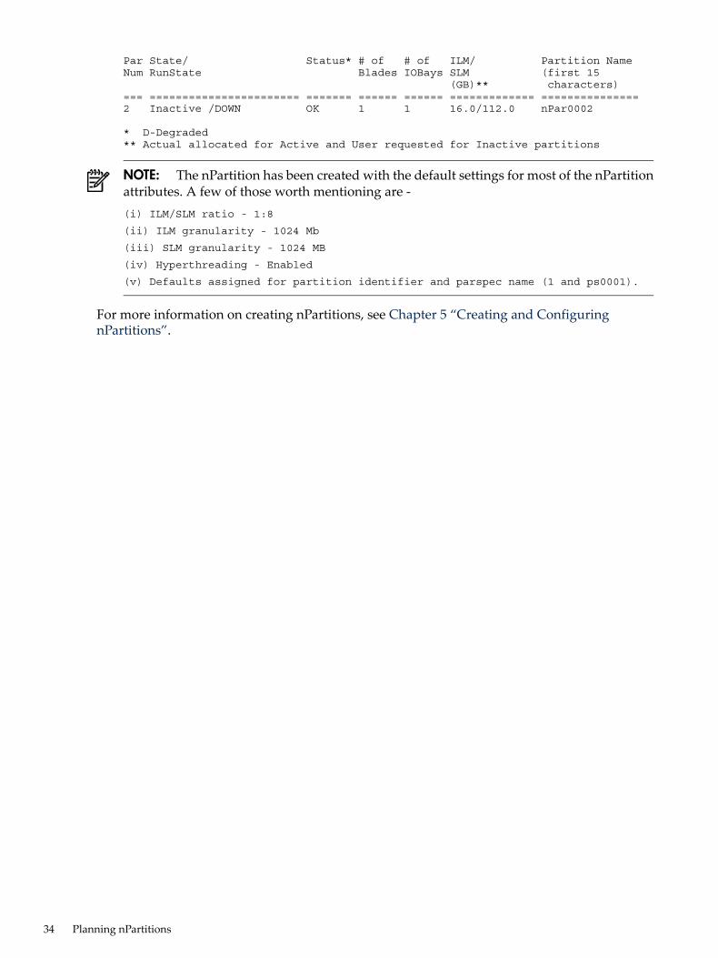
Par State/ Status* # of # of ILM/ Partition NameNum RunState Blades IOBays SLM (first 15 (GB)** characters)=== ======================= ======= ====== ====== ============= ===============2 Inactive /DOWN OK 1 1 16.0/112.0 nPar0002
* D-Degraded** Actual allocated for Active and User requested for Inactive partitions
NOTE: The nPartition has been created with the default settings for most of the nPartitionattributes. A few of those worth mentioning are -(i) ILM/SLM ratio - 1:8
(ii) ILM granularity - 1024 Mb
(iii) SLM granularity - 1024 MB
(iv) Hyperthreading - Enabled
(v) Defaults assigned for partition identifier and parspec name (1 and ps0001).
For more information on creating nPartitions, see Chapter 5 “Creating and ConfiguringnPartitions”.
34 Planning nPartitions

5 Creating and Configuring nPartitionsThis chapter has procedures for creating, configuring, and managing nPartitions on HP Superdome2 server. This chapter discusses the following topics:• “Tools for Configuring nPartitions”• “Granting permission for an OS to manage nPartitions”• “Task Summaries for Creating and Configuring nPartitions”• “Partition Default Attributes”• “Partition Specifications (parspec)”• “Creating a New nPartition”• “Verifying Newly Created nPartitions”• “Removing (Deleting) an nPartition”• “Renaming an nPartition”• “Assigning (Adding) Blades and I/O Bays to an nPartition”• “Unassigning (Removing) Blades and I/O Bays from an nPartition”• “Renaming a Server Complex”• “Setting Blade Attributes”
Tools for Configuring nPartitionsYou can configure and manage nPartitions using the Onboard Partition Manager.The Onboard Partition Manager is a set of tools integrated with the HP Superdome 2 OnboardAdministrator. The Onboard Administrator Partition Management GUI replaces the legacyParMgr GUI which ran on an operating system in a partition. The Onboard Partition Managertools are a complete set of nPartition and vPar configuration and management tools providingnPartition and vPar configuration information as well as many other enhancements over theprevious GUI tool. The OA GUI is accessible from the partition side through SMH.
OA CLITo launch the OA CLI, complete the following steps:1. To access the OA CLI, use a telnet or an ssh connection to the OA address.2. Enter the OA Administrator password.
NOTE: The original Administrator password is available on a sticker on the OA module.
OA GUITo access the OA GUI, complete the following steps:1. Open a browser and type the url: http://<OA address>>. “OA GUI” shows the Onboard
Administrator login screen.
Tools for Configuring nPartitions 35

Figure 5-1 OA GUI Login Screen
2. Enter the OA Administrator password.
NOTE: The original Administrator password is available on a sticker on the OA module.
nPartition Commands
Commands for Configuring nPartitionsYou can use the nPartition commands to create, modify, monitor, and remove nPartitions.Table 3-1 describes the nPartition configuration commands.
NOTE: To execute partition commands from the operating system, root or IPMI LAN accessis required.
Table 5-1 nPartition Commands Descriptions
DescriptionCommand
Create a new nPartition. For more information, see help parcreate .parcreate
Display or change default values of certain nPartition attributes. For more information, see helppardefault .
pardefault
Modify an existing nPartition. For more information, see help parmodify .parmodify
Configure partition configuration privilege for nPartitions and vPars . For more information, seehelp parperm .
NOTE: The parperm command is available only from the onboard administrator.
parperm
Remove an existing nPartition. For more information, see help parremove .parremove
Display nPartition information and hardware details for a server complex. For more information,see help parstatus.
parstatus
Granting permission for an OS to manage nPartitionsUse the parperm command to remove restrictions which prevent an operating system runningin a partition from performing partition configuration operations on other partitions. By default,a partition can only perform partition configuration operations on itself. The commands to displaypartition status do not need any authorization and are allowed from any partition.The following command removes nPartition configuration restriction from an OS running innPartition 1, enabling it to perform nPartition configuration operations on nPartitions other thannPartition 1.parperm npar on 1
For more information, see help parperm.
36 Creating and Configuring nPartitions
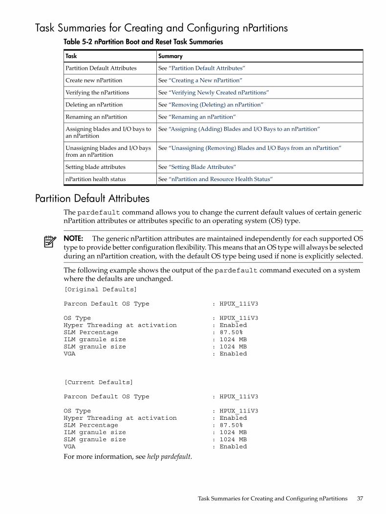
Task Summaries for Creating and Configuring nPartitionsTable 5-2 nPartition Boot and Reset Task Summaries
SummaryTask
See “Partition Default Attributes”Partition Default Attributes
See “Creating a New nPartition”Create new nPartition
See “Verifying Newly Created nPartitions”Verifying the nPartitions
See “Removing (Deleting) an nPartition”Deleting an nPartition
See “Renaming an nPartition”Renaming an nPartition
See “Assigning (Adding) Blades and I/O Bays to an nPartition”Assigning blades and I/O bays toan nPartition
See “Unassigning (Removing) Blades and I/O Bays from an nPartition”Unassigning blades and I/O baysfrom an nPartition
See “Setting Blade Attributes”Setting blade attributes
See “nPartition and Resource Health Status”nPartition health status
Partition Default AttributesThe pardefault command allows you to change the current default values of certain genericnPartition attributes or attributes specific to an operating system (OS) type.
NOTE: The generic nPartition attributes are maintained independently for each supported OStype to provide better configuration flexibility. This means that an OS type will always be selectedduring an nPartition creation, with the default OS type being used if none is explicitly selected.
The following example shows the output of the pardefault command executed on a systemwhere the defaults are unchanged.[Original Defaults]
Parcon Default OS Type : HPUX_11iV3
OS Type : HPUX_11iV3Hyper Threading at activation : EnabledSLM Percentage : 87.50%ILM granule size : 1024 MBSLM granule size : 1024 MBVGA : Enabled
[Current Defaults]
Parcon Default OS Type : HPUX_11iV3
OS Type : HPUX_11iV3Hyper Threading at activation : EnabledSLM Percentage : 87.50%ILM granule size : 1024 MBSLM granule size : 1024 MBVGA : Enabled
For more information, see help pardefault.
Task Summaries for Creating and Configuring nPartitions 37

Creating a New nPartitionThis section describes the procedure to create an nPartition using the OA CLI and the GUI.
Creating a New nPartition Using the OA CLIYou can use the parcreate command to create a new nPartition on HP Superdome 2. Thecommand takes the specified blades and I/O bays and assigns them to the new nPartition. If annPartition number is not specified, the command finds an available nPartition number andassigns it to the new nPartition. Likewise if an nPartition name is not specified, a default nameof the format nParnnnn (example: nPar0001) is given to the new nPartition (where nnnn is a 4digit nPartition number). Superuser permission is required to run this command from an operatingsystem within a partition. When the command is invoked from Onboard Administrator (OA),it requires the operator level privilege or higher. This is applicable for all partition commands.For parstatus and vparstatus, you must have user level privilege or higher.To create a two-blade nPartition nextPartition that uses the blades 1 and 3 in enclosure 1and the IO slot in IOX enclosure 5, bay 1:parcreate -p nextPartition -a blade:1/1:::: -a blade:1/3:::: -a io:5/1:
Creating a New nPartition Using the OA GUITo create a new nPartition using the OA GUI, complete the following steps:1. Open the OA GUI.2. Login using the administrator credentials.3. Click Complex nPartitions in the Systems and Devices tab.4. In the Complex nPartitions Summary tab, click create.5. Enter the nPartition Name.6. Click Create NPartition.7. Ensure that you select all the resources by expanding the rows.8. Click Apply.The nPartition is created. You will be redirected to the Modify nPartition screen (seeFigure 5-2 “Modify nPartition Window”), where you can assign resources to the created npartition.
Figure 5-2 Modify nPartition Window
Verifying Newly Created nPartitionsTo verify that the partitions are defined as desired, you can perform either of the following steps:• Theparstatus –P command shows the summary data as shown in the following example:
parstatus -P[Partition]
Par State/ Status* # of # of ILM/ Partition Name
38 Creating and Configuring nPartitions

Num RunState Blades IOBays SLM (first 15 (GB)** characters)=== ======================= ======= ====== ====== ============= ===============1 Inactive /DOWN OK 2 0 32.0/224.0 nPar00012 Inactive /DOWN OK 1 1 16.0/112.0 nPar00023 Inactive /DOWN OK 1 1 16.0/112.0 nPar0003
* D-Degraded** Actual allocated for Active and User requested for Inactive partitions
• The parstatus –V –p {partition_id} command gives the details on any specificpartition. For the first nPartition, you could either use parstatus –Vp1 or parstatus–V –p nPar0001 as shown in the following example:User Specified Max number of vpars : 16[Partition]
Partition Number : 1Partition Name : nPar0001Current Parspec Name : ps0001Parspec Name at next boot :State : ActiveRunState : EFIOS Type : HPUX_11iV3OS Type at next boot : HPUX_11iV3Hyper Threading at activation : EnabledHyper Threading at next boot : EnabledActive ILO : 1/1/0/2/2Firmware Revision : 1.0.30Total Good Memory Size : 256.0 GBTotal Memory Available : 256.0 GBTotal Interleave Memory : 30.0 GBTotal SLM : 224.0 GBSLM at next boot : 224.0 GBILM granule size : 1024 MBILM granule size at next boot : 1024 MBSLM granule size : 1024 MBSLM granule size at next boot : 1024 MBMax number of ILM granules possible : 1024Max number of SLM granules possible : 1024User Specified Max number of blades : 8Max number of blades at next boot : 8User Specified Max number of vpars : 16Max number of vpars at next boot : 16Current boot mode : nparsNext boot mode : nparsParspec Change Policy : EnabledVGA : EnabledVGA next boot mode : EnabledPending Deletion : no
[Blade]
Enclosure/ Usage/ CPU Memory Use Par PendingBlade Status* OK/ (GB) On Num Deletion Indicted/ OK/ Next Deconf/ Indicted/ Boot Max Deconf========== ======================= ========= =============== ==== === ========1/1 Active Base /OK 8/0/0/8 128.0/0.0/0.0 yes 1 no1/2 Active Base /OK 8/0/0/8 128.0/0.0/0.0 yes 1 no
* D-Deconfigured I-Indicted
[IOBay]
Enclosure/ Usage/ Par PendingIOBay Status* Num Deletion========== ======================= === ========
Verifying Newly Created nPartitions 39

* D-Deconfigured I-Indicted
Removing (Deleting) an nPartitionThis section describes the procedure to remove an nPartition using both the OA interfaces.
Removing (Deleting) an nPartition Using the OA CLIThe parremove command removes an existing nPartition. This unassigns all blades and I/Obays from the nPartition and destroys the partition. The target nPartition must be inactive unlessthe -F option is used. By default, the current partition specification (parspec) associated withthe nPartition is not removed when the nPartition is removed. The current parspec associatedwith the nPartition becomes an alternate parspec and can be reused later. If -Z option is specified,the command removes the current parspec when the nPartition is removed.The syntax for parremove command is:parremove -p nPartition_id [-Z] [-F]
An example for removing an nPartition is:parremove -p 2
Removing (Deleting) an nPartition Using the OA GUITo remove an inactive nPartition, select the desired nPartition from the Complex nPartitionstable and then click Delete.
Renaming an nPartitionThis section describes the procedure to rename an nPartition using both the OA interfaces.
Renaming an nPartition Using the OA CLIUse the parmodify command to rename the nPartition. Following is the syntax.parmodify p- <nPar_id> -P <new_nPartition_name>
Where <nPar_ID> is the integer nPartition number which indicates which nPartition is gettingrenamed, andnew_nPartition_name is the new name for the nPartition.This command specifies a new name for the nPartition being modified, that is, after allmodifications are successfully applied to nPartition_id, it is renamed if no partition with thatname exists.An nPartition name should at least have one of the following non-numeric characters: a-z, A-Z,dash (-), underscore (_), and period (.). No other non-numeric characters are allowed in annPartition name. An nPartition name should not start with a dash (-). An nPartition name withthe same format as the default name can only be specified if the specified name matches thenPartition number.
Renaming an nPartition Using the OA GUITo rename an nPartition using the GUI, complete the following steps:1. Select the nPartition from the left navigation pane.2. Click Modify nPartition.3. Enter the new name in the nPartition Name field.4. Click Apply.
40 Creating and Configuring nPartitions

Assigning (Adding) Blades and I/O Bays to an nPartitionThis section describes the procedure to assign blades and I/O bays.
Assigning (Adding) Blades and I/O Bays to an nPartition Using the OA CLIThe syntax for adding a blade is:parmodify -p <nParId/nPar_name> -a <resource_path>
For more information, see help parcreate and help parmodify.The following command adds the blade in enclosure 1, slot 3 to the existing nPartition 2.parmodify -p 2 -a blade:1/3:base:y:ri:50%
The syntax for adding an I/O bay is:parmodify -p <nParId/nPar_name> -a io:iobay_path:[use_on_next_boot][:failure_usage]
For more information, see the OA help, help parcreate and help parmodify .The following command adds I/O bay 1 in enclosure 6 to the existing nPartition 2.parmodify -p 2 -a io:6/1:
Assigning (Adding) Blades and I/O Bays to an nPartition Using the OA GUITo assign blades and I/O Bays to an nPartition using the OA GUI, complete the following steps:1. Select the nPartition from the left navigation pane and click modify nPartition.2. Expand the Blade Resources option. Figure 5-3 “Blade Resources Option” shows the blade
resource screen.
Figure 5-3 Blade Resources Option
3. Select the blade resources that you want to assign to the nPartition.4. Expand the IOX Resources option. Figure 5-4 “IOX Resources Option” shows the IOX
Resources screen.
Assigning (Adding) Blades and I/O Bays to an nPartition 41

Figure 5-4 IOX Resources Option
5. Select the I/O bay.6. Click Apply to commit your configuration changes.
To cancel an operation, navigate away from the Modify nPartition screen.
The blades and I/O bay are assigned to the nPartition.
Unassigning (Removing) Blades and I/O Bays from an nPartitionThis section describes the procedure to unassign blades and I/O bays from an nPartition.
Unassigning (Removing) Blades and I/O Bays from an nPartition Using the OA CLIThe following command shows the removal of a blade in enclosure 1 slot 3 from the existingnPartition 2:parmodify -p 2 -d blade:1/3
The following command deletes I/O bay 1 in enclosure 6 to the existing nPartition 2:parmodify -p 2 -d io:6/1
NOTE: If the nPartition is active, the blades and I/O bays are unassigned at the next reboot ofthe nPartition.
Unassigning (Removing) Blades and I/O Bays from an nPartition Using the OA GUITo unassign blades and I/O bays from an nPartition using the OA GUI, complete the followingsteps:1. Select the nPartition from the left hand navigation pane and click modify nPartition.2. Expand the Blade Resources option. Figure 5-3 “Blade Resources Option” shows the blade
resource screen.
42 Creating and Configuring nPartitions

Figure 5-5 Blade Resources Option
3. Uncheck the blade resources that you want to unassign from the nPartition.4. Expand the IOX Resources option. Figure 5-4 “IOX Resources Option” shows the IOX
Resources screen.
Figure 5-6 IOX Resources Option
5. Uncheck the I/O bay(s) that you want to unassign.6. Click Apply.The blades and I/O resources are unassigned from the nPartition.
Unassigning (Removing) Blades and I/O Bays from an nPartition 43
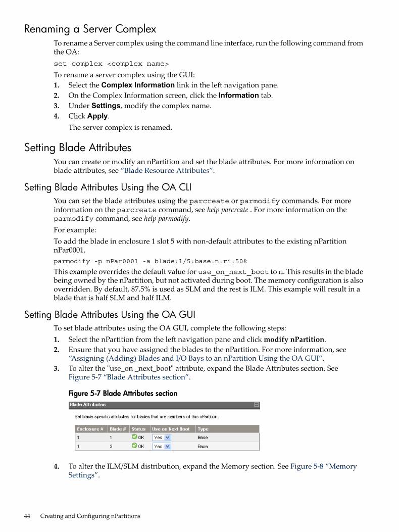
Renaming a Server ComplexTo rename a Server complex using the command line interface, run the following command fromthe OA:set complex <complex name>
To rename a server complex using the GUI:1. Select the Complex Information link in the left navigation pane.2. On the Complex Information screen, click the Information tab.3. Under Settings, modify the complex name.4. Click Apply.
The server complex is renamed.
Setting Blade AttributesYou can create or modify an nPartition and set the blade attributes. For more information onblade attributes, see “Blade Resource Attributes”.
Setting Blade Attributes Using the OA CLIYou can set the blade attributes using the parcreate or parmodify commands. For moreinformation on the parcreate command, see help parcreate . For more information on theparmodify command, see help parmodify.For example:To add the blade in enclosure 1 slot 5 with non-default attributes to the existing nPartitionnPar0001.parmodify -p nPar0001 -a blade:1/5:base:n:ri:50%
This example overrides the default value for use_on_next_boot to n. This results in the bladebeing owned by the nPartition, but not activated during boot. The memory configuration is alsooverridden. By default, 87.5% is used as SLM and the rest is ILM. This example will result in ablade that is half SLM and half ILM.
Setting Blade Attributes Using the OA GUITo set blade attributes using the OA GUI, complete the following steps:1. Select the nPartition from the left navigation pane and click modify nPartition.2. Ensure that you have assigned the blades to the nPartition. For more information, see
“Assigning (Adding) Blades and I/O Bays to an nPartition Using the OA GUI”.3. To alter the "use_on _next_boot" attribute, expand the Blade Attributes section. See
Figure 5-7 “Blade Attributes section”.
Figure 5-7 Blade Attributes section
4. To alter the ILM/SLM distribution, expand the Memory section. See Figure 5-8 “MemorySettings”.
44 Creating and Configuring nPartitions

Figure 5-8 Memory Settings
5. Select the appropriate attributes.6. Click Apply.The blade attributes are set.
Setting Blade Attributes 45

46

6 Booting and Resetting Partitions (nPartitions and vPars)This chapter introduces Partition system boot and reset concepts, configuration options, andprocedures for booting and resetting Partitions. This chapter covers boot details for HP-UX 11iv3 operating system and the OA CLI and GUI.This chapter discusses the following topics:• “Overview of Partition System Booting”• “Accessing the OA”• “Booting to EFI and Preparing for Operating System Installation”• “Task Summaries for Rebooting and Resetting Partitions”• “HP Superdome 2 Boot Support”• “nPartition and Resource Health Status”
Overview of Partition System BootingThis section provides an overview of the Partition system boot process for HP Superdome 2systems. On HP Superdome 2 with enclosures and blades, system resources are configured intoone or more nPartitions. The nPartitions may be further divided into virtual partitions (vPars).Each nPartition includes the blades (with processors and memory) assigned to it and the I/Oexpansion enclosure with I/O bays. Each vPar includes CPU cores, memory, and I/O that maybe addressed at the individual slot level.A Partition (nPartition or vPar) can boot and reboot independently of any other Partitions in thesame server complex. Each Partition runs its own firmware and has its own system bootenvironment. Partitions provide hardware and software fault isolation: a reset, TOC, or MCAin one Partition does not affect any other Partition. The OA provides commands to boot a partition.An nPartition provides a platform for booting an operating system that is electrically isolatedfrom other partitions in the complex. You can choose to run either a single OS instance, anIntegrity VM host (and guests), or vPar in any nPartition.
Accessing the OAYou can configure and manage partitions using the Onboard Partition Manager.The Onboard Partition Manager is a set of tools integrated with the HP Superdome 2 OnboardAdministrator. The tools consist of both command line and graphical user interfaces. The OnboardAdministrator Partition Management GUI replaces the legacy ParMgr GUI which ran on anoperating system in a partition. The Onboard Partition Manager tools are a complete set ofnPartition and vPar configuration and management tools providing nPartition and vParconfiguration information as well as many other enhancements over the previous GUI tool. TheOA GUI is accessible from the partition side through SMH.
OA CLITo launch the OA CLI, complete the following steps:1. To access the OA CLI, use a telnet or an ssh connection to the OA address.2. Enter the OA Administrator password.
NOTE: The original Administrator password is available on a sticker on the OA module.
For more information on activating a partition from CLI see “Booting from the CLI ”
OA GUITo access the OA GUI, complete the following steps:
Overview of Partition System Booting 47

1. Open a browser and type the url: http://<OA address>>. “OA GUI” shows the OnboardAdministrator login screen.
Figure 6-1 OA GUI Login Screen
2. Enter the OA Administrator password.
NOTE: The original Administrator password is available on a sticker on the OA module.
For more information on activating a partition from GUI see “Booting from the GUI”
Booting to EFI and Preparing for Operating System InstallationYou can access a partition console and its EFI system boot environment through the OA. Eachpartition has its own system boot environment that provides you a method for interacting withthe partition before an operating system has booted on it. The system boot environment isaccessible through the partition console during the time after the blades assigned to the partitionhave booted and completed nPartition rendezvous and before the partition begins loading anoperating system.This section discusses the following topics:• “Booting from the CLI ”• “Booting from the GUI”• “Getting a Console Using the CLI”• “Getting a Console Using the GUI”• “Confirming the Installed IO cards”• “Getting MAC Addresses for Ignite-UX”
Booting from the CLITo activate a partition from the command line, you can either use the poweron partition{identifier} command, the bo command, or the pe command.
poweron partition 2Poweron request sent to partition 2. Operation initiated successfully.Please run PARSTATUS/VPARSTATUS or SHOW SYSLOG OA to determine the completionstatus of the operation.
48 Booting and Resetting Partitions (nPartitions and vPars)
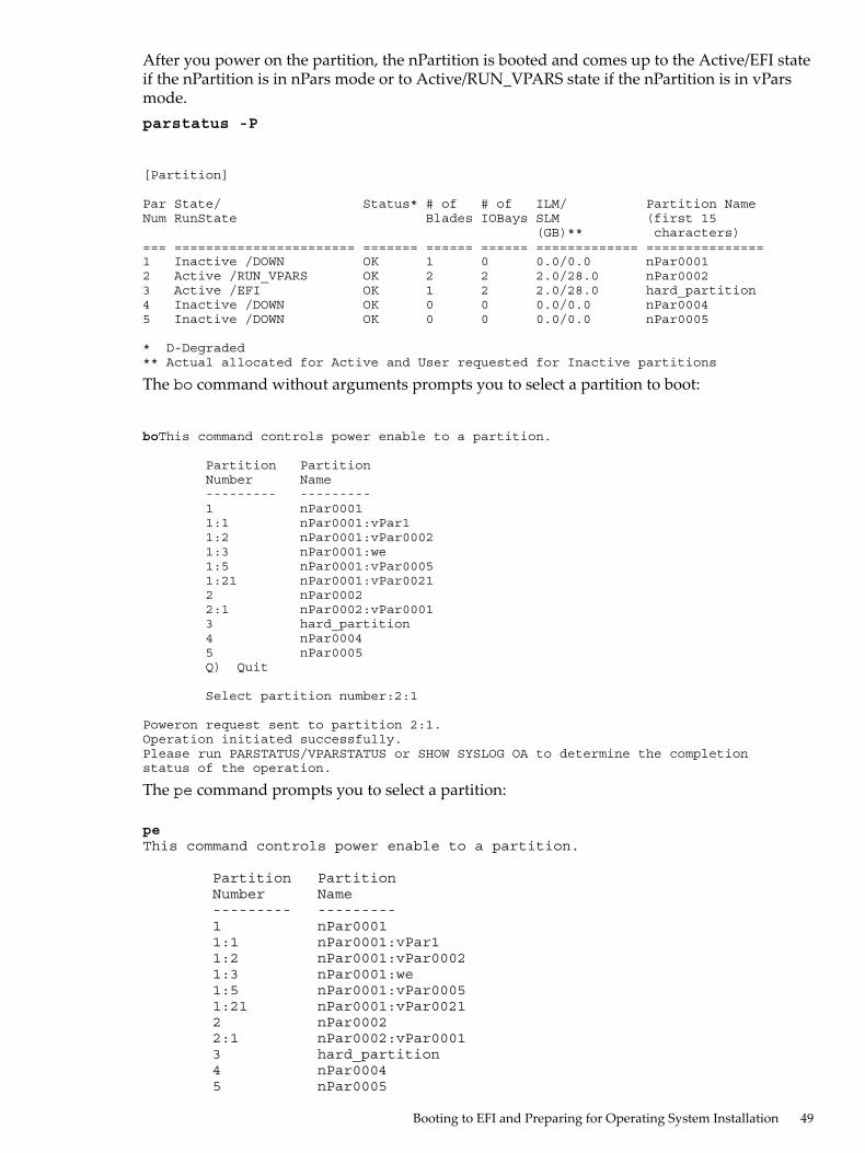
After you power on the partition, the nPartition is booted and comes up to the Active/EFI stateif the nPartition is in nPars mode or to Active/RUN_VPARS state if the nPartition is in vParsmode.parstatus -P
[Partition]
Par State/ Status* # of # of ILM/ Partition NameNum RunState Blades IOBays SLM (first 15 (GB)** characters)=== ======================= ======= ====== ====== ============= ===============1 Inactive /DOWN OK 1 0 0.0/0.0 nPar00012 Active /RUN_VPARS OK 2 2 2.0/28.0 nPar00023 Active /EFI OK 1 2 2.0/28.0 hard_partition4 Inactive /DOWN OK 0 0 0.0/0.0 nPar00045 Inactive /DOWN OK 0 0 0.0/0.0 nPar0005
* D-Degraded** Actual allocated for Active and User requested for Inactive partitions
The bo command without arguments prompts you to select a partition to boot:
boThis command controls power enable to a partition.
Partition Partition Number Name --------- --------- 1 nPar0001 1:1 nPar0001:vPar1 1:2 nPar0001:vPar0002 1:3 nPar0001:we 1:5 nPar0001:vPar0005 1:21 nPar0001:vPar0021 2 nPar0002 2:1 nPar0002:vPar0001 3 hard_partition 4 nPar0004 5 nPar0005 Q) Quit
Select partition number:2:1
Poweron request sent to partition 2:1. Operation initiated successfully.Please run PARSTATUS/VPARSTATUS or SHOW SYSLOG OA to determine the completionstatus of the operation.
The pe command prompts you to select a partition:
peThis command controls power enable to a partition.
Partition Partition Number Name --------- --------- 1 nPar0001 1:1 nPar0001:vPar1 1:2 nPar0001:vPar0002 1:3 nPar0001:we 1:5 nPar0001:vPar0005 1:21 nPar0001:vPar0021 2 nPar0002 2:1 nPar0002:vPar0001 3 hard_partition 4 nPar0004 5 nPar0005
Booting to EFI and Preparing for Operating System Installation 49

Q) Quit Select partition number: 2:1
The power state is OFF for partition 2:1. In what state do you want the power? (ON/OFF) on
Booting from the GUIThe individual partition screens may be reached either from the left navigation pane regardlessof whether the partition is an nPartition or a vPar.1. Select a partition that you want to activate.
Figure 6-2 nPartition Status Information
Figure 6-3 vPar Status information
2. Select the Virtual Devices tab and click on theMomentary Press button.
Figure 6-4 nPartition Virtual Devices tab
50 Booting and Resetting Partitions (nPartitions and vPars)
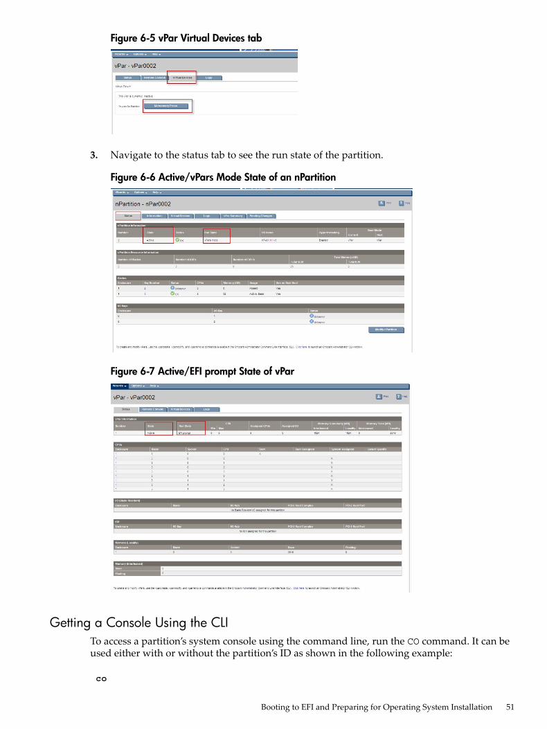
Figure 6-5 vPar Virtual Devices tab
3. Navigate to the status tab to see the run state of the partition.
Figure 6-6 Active/vPars Mode State of an nPartition
Figure 6-7 Active/EFI prompt State of vPar
Getting a Console Using the CLITo access a partition’s system console using the command line, run the CO command. It can beused either with or without the partition’s ID as shown in the following example:
co
Booting to EFI and Preparing for Operating System Installation 51

Partition Partition Number Name --------- --------- 1 nPar0001 2 nPar0002 2:1 nPar0002:vPar0001 Q) Quit Select partition number: 2:1----Log Snippet-------------Log Snippet--------- Welcome to the Superdome 2 console <use <Ctrl-b> to exit.>Shell>
Alternatively, you can also use the CONNECT PARTITION command to connect to a partition.
connect partition 2----Log Snippet---------
----Log Snippet---------
Welcome to the Superdome 2 console <use <Ctrl-b> to exit.>
Getting a Console Using the GUITo access a partition's system console using the GUI, select the Remote Console tab and clickon the Remote Serial Console link.
Figure 6-8 Remote Console Tab (nPar)
Figure 6-9 Remote Console Tab (vPar)
Confirming the Installed IO cardsOnce the system console has been accessed, and the partition has been booted to EFI, the EFIcommands info io and devices can be used to display the contents of the I/O bays as shownin the following example:
info io
PLATFORM I/O INFORMATION
52 Booting and Resetting Partitions (nPartitions and vPars)
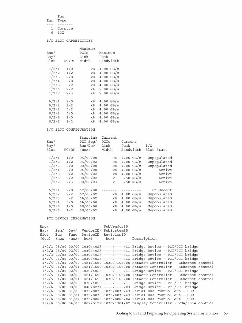
Enc Enc Type --- ------- 1 Compute 6 IOX
I/O SLOT CAPABILITIES
Maximum Enc/ PCIe Maximum Bay/ Link Peak Slot RC/RP Width Bandwidth ------ ----- ------- --------- 1/2/1 1/0 x8 4.00 GB/s 1/2/2 1/2 x8 4.00 GB/s 1/2/3 2/0 x8 4.00 GB/s 1/2/4 0/0 x8 4.00 GB/s 1/2/5 0/2 x8 4.00 GB/s 1/2/6 2/2 x4 2.00 GB/s 1/2/7 2/3 x4 2.00 GB/s
6/2/1 2/0 x8 4.00 GB/s 6/2/2 2/2 x8 4.00 GB/s 6/2/3 0/2 x8 4.00 GB/s 6/2/4 0/0 x8 4.00 GB/s 6/2/5 1/0 x8 4.00 GB/s 6/2/6 1/2 x8 4.00 GB/s
I/O SLOT CONFIGURATION
Starting Current Enc/ PCI Seg/ PCIe Current Bay/ Bus/Dev Link Peak I/O Slot RC/RP (hex) Width Bandwidth Slot State ------ ----- -------- ------- --------- ------------ 1/2/1 1/0 05/00/00 x8 4.00 GB/s Unpopulated 1/2/2 1/2 05/00/02 x8 4.00 GB/s Unpopulated 1/2/3 2/0 00/08/00 x8 4.00 GB/s Unpopulated 1/2/4 0/0 04/00/00 x8 4.00 GB/s Active 1/2/5 0/2 04/00/02 x8 4.00 GB/s Active 1/2/6 2/2 00/08/02 x1 250 MB/s Active 1/2/7 2/3 00/08/03 x1 250 MB/s Active
6/2/1 2/0 6C/00/00 ------- --------- HW Deconf 6/2/2 2/2 6C/00/02 x8 4.00 GB/s Unpopulated 6/2/3 0/2 6A/00/02 x8 4.00 GB/s Unpopulated 6/2/4 0/0 6A/00/00 x8 4.00 GB/s Unpopulated 6/2/5 1/0 6B/00/00 x8 4.00 GB/s Unpopulated 6/2/6 1/2 6B/00/02 x8 4.00 GB/s Unpopulated
PCI DEVICE INFORMATION
Enc/ SubVendorIDBay/ Seg/ Dev/ VendorID/ SubSystemIDSlot Bus Func DeviceID RevisionID(dec) (hex) (hex) (hex) (hex) Description------ ----- ----- --------- ------------ ----------- 1/2/1 05/00 00/00 103C/402F ----/----/11 Bridge Device - PCI/PCI bridge 1/2/2 05/00 02/00 103C/402F ----/----/11 Bridge Device - PCI/PCI bridge 1/2/3 00/08 00/00 103C/402F ----/----/11 Bridge Device - PCI/PCI bridge 1/2/4 04/00 00/00 103C/402F ----/----/11 Bridge Device - PCI/PCI bridge 1/2/4 04/01 00/00 14E4/1650 103C/7105/00 Network Controller - Ethernet control 1/2/4 04/01 00/01 14E4/1650 103C/7105/00 Network Controller - Ethernet control 1/2/5 04/00 02/00 103C/402F ----/----/11 Bridge Device - PCI/PCI bridge 1/2/5 04/80 00/00 14E4/1650 103C/7105/00 Network Controller - Ethernet control 1/2/5 04/80 00/01 14E4/1650 103C/7105/00 Network Controller - Ethernet control 1/2/6 00/08 02/00 103C/402F ----/----/11 Bridge Device - PCI/PCI bridge 1/2/6 00/0B 00/00 104C/8231 ----/----/03 Bridge Device - PCI/PCI bridge 1/2/6 00/0C 01/00 1033/0035 1033/0035/43 Serial Bus Controllers - USB 1/2/6 00/0C 01/01 1033/0035 1033/0035/43 Serial Bus Controllers - USB 1/2/6 00/0C 01/02 1033/00E0 1033/00E0/04 Serial Bus Controllers - USB 1/2/6 00/0C 04/00 1002/515E 103C/1304/02 Display Controller - VGA/8514 control
Booting to EFI and Preparing for Operating System Installation 53

1/2/7 00/08 03/00 103C/402F ----/----/11 Bridge Device - PCI/PCI bridge 1/2/7 00/0D 00/00 103C/3306 103C/3309/04 Base System Peripherals - Other syste 1/2/7 00/0D 00/02 103C/3307 103C/3309/04 Base System Peripherals - Other syste 1/2/7 00/0D 00/04 103C/3300 103C/3309/01 Serial Bus Controllers - USB
6/2/2 6C/00 02/00 103C/402F ----/----/11 Bridge Device - PCI/PCI bridge 6/2/3 6A/00 02/00 103C/402F ----/----/11 Bridge Device - PCI/PCI bridge 6/2/4 6A/00 00/00 103C/402F ----/----/11 Bridge Device - PCI/PCI bridge 6/2/5 6B/00 00/00 103C/402F ----/----/11 Bridge Device - PCI/PCI bridge 6/2/6 6B/00 02/00 103C/402F ----/----/11 Bridge Device - PCI/PCI bridge
Fast initialization: Enabled
Getting MAC Addresses for Ignite-UXThe EFI commandlanaddress can be used to list the MAC addresses of every network interfacein a partition:Shell> lanaddress
LAN Address Information
LAN Address Path ----------------- ----------------------------------------M 001 Mac(002655A9F352) PcieRoot(0x0)/Pci(0x0,0x0)/Pci(0x0,0x0)/MAC(002655A9F352,0x0) 002 Mac(002655A9F356) PcieRoot(0x0)/Pci(0x0,0x0)/Pci(0x0,0x1)/MAC(002655A9F356,0x0)M 003 Mac(002655A9F35A) PcieRoot(0x0)/Pci(0x2,0x0)/Pci(0x0,0x0)/MAC(002655A9F35A,0x0) 004 Mac(002655A9F35E) PcieRoot(0x0)/Pci(0x2,0x0)/Pci(0x0,0x1)/MAC(002655A9F35E,0x0)
NOTE: The first four addresses, each of which have a path of the formPcieRoot()/Pci()/Pci()/MAC() are LAN on Motherboard modules directly on a blade.
Task Summaries for Rebooting and Resetting PartitionsTable 6-1 describes the main nPartition boot and reset tasks and provides brief summaries andreferences for detailed procedures.You can perform the nPartition boot tasks in Table 6-1 “nPartition Boot and Reset TaskSummaries” using either the OA CLI or the OA GUI.
Table 6-1 nPartition Boot and Reset Task Summaries
SummaryTask
Boots the partition. See “POWERON PARTITION”.POWERON (pe)1
Shuts down the partition. See “POWEROFF PARTITION”.POWEROFF (pe)
Reboots the OS on the specified nPartition or virtual partition. See“REBOOT PARTITION”.
REBOOT (rs)
Connect or disconnect the DVD module to the specified partition. See“SET PARTITION DVD”.
SET PARTITION DVD
Performs a transfer-of-control reset of the specified nPartition or virtualpartition. See “Force System Reset and Crash Dump (TOC) PARTITION”.
TOC (tc)
Displays the version of the firmware bundle currently installed on theserver blades within the specified partition(s). See “UPDATE SHOWNPARTITION”.
UPDATE SHOW
Displays information about the DVD drive attached to the specifiedpartition. See “SHOW PARTITION DVD”.
SHOW PARTITION DVD
Displays information about the specified partition(s). See “SHOWPARTITION INFO”.
SHOW PARTITION INFO
54 Booting and Resetting Partitions (nPartitions and vPars)

Table 6-1 nPartition Boot and Reset Task Summaries (continued)
SummaryTask
TheUPDATE NPARTITION command downloads a new flash image fromthe network or a USB drive attached to the DVD module, or a DVD in theenclosure DVD drive in the monarch enclosure and uses it to update thefirmware for HP Superdome 2 cell blades within the specified partition(s).See“UPDATE NPARTITION”.
UPDATE NPARTITION
Displays the version of the firmware bundle currently installed on theserver blades within the specified partition(s). See “UPDATE SHOWNPARTITION”.
UPDATE SHOW NPARTITION
Updates the Superdome system's firmware (except I/O firmware). See“UPDATE FIRMWARE”.
UPDATE FIRMWARE
Displays the configured Superdome firmware version and lists any of thefollowing Superdome 2 devices whose installed firmware version differsfrom the system's configured firmware version: blade, XFM, SIOX, OA,GPSM. See “UPDATE SHOW NPARTITION”.
UPDATE SHOW FIRMWARE
1 When any of the 2-letter equivalents for POWERON/POWEROFF/TOC/REBOOT (namely, pe, tc, and rs respectively)are executed without any arguments, a list of available partitions on which the command may be excercised aredisplayed.
POWEROFF PARTITION
From the CLI• Command:
POWEROFF PARTITION {{<nPar ID>} [:vPar ID>] | ALL} [FORCE] [OVERRIDE]}
• Description:Gracefully shuts down any OS running on the specified nPartition or virtual partition andbrings it to an inactive state. The active blades and IO interconnects in the nPartition arepowered off if the target specified is an nPartition.The OVERRIDE argument shuts down all virtual partitions in the specified nPartition.
Task Summaries for Rebooting and Resetting Partitions 55

NOTE: An OVERRIDE option is required to affect a change in mode or when a destructiveoperation needs to be applied to all vPars in an nPartition. HP Superdome 2 partitionmanagement supports two modes of operation for an nPartition: the “nPars” mode and the“vPars” mode. The mode is an attribute of an nPartition. When in nPars mode, an nPartitionnormally boots up as a single OS instance (or HPVM host). When in vPars mode, an nPartitionnormally boots up a set of explicitly defined virtual partitions, each running its own OSinstance. The mode of operation can be switched between the two using partition CLIcommands and takes effect only when the nPartition is rebooted.When in nPars mode, vpar definitions may or may not exist - they are not used if they doexist. There are some deviations from the normal policy in certain scenarios to facilitate abetter customer experience. Normal behavior is to disallow vPars operations when in nParsmode and to disallow nPartition operations when in vPars mode, unless the command isgiven with the OVERRIDE option. For example, if an operation is targeted at a vPar whilein nPars mode, the command will be rejected with appropriate error message explainingthe reason for the failure. The OVERRIDE option overrides this normal behavior, and canresult in a change in mode or can apply a destructive operation to all vPars in an nPar.
The FORCE argument shuts down the specified partition ungracefully. If an OS is not runningon the partition, the FORCE argument is required to power off the partition.
CAUTION: The POWEROFF PARTITION ALL command requires the FORCE argumentand ungracefully shuts down all partitions. This can cause a partition to lose data andpossibly become unstable. On the other hand, if a partition is at EFI, the FORCE argumentis required to shut it down.
• Access level/Bay level:OA Administrator, OA Operator
• Restriction:You must be connected to the monarch OA.
From the GUI1. Select an active partition.
Figure 6-10 Status Information of an nPartition
56 Booting and Resetting Partitions (nPartitions and vPars)

Figure 6-11 Status Information of a vPar
2. Select the Virtual Devices tab.• For force poweroff, click the Reset button.• For graceful poweroff, click the Warm Boot button.
Figure 6-12 Graceful and Force Poweroff (nPartition)
Task Summaries for Rebooting and Resetting Partitions 57
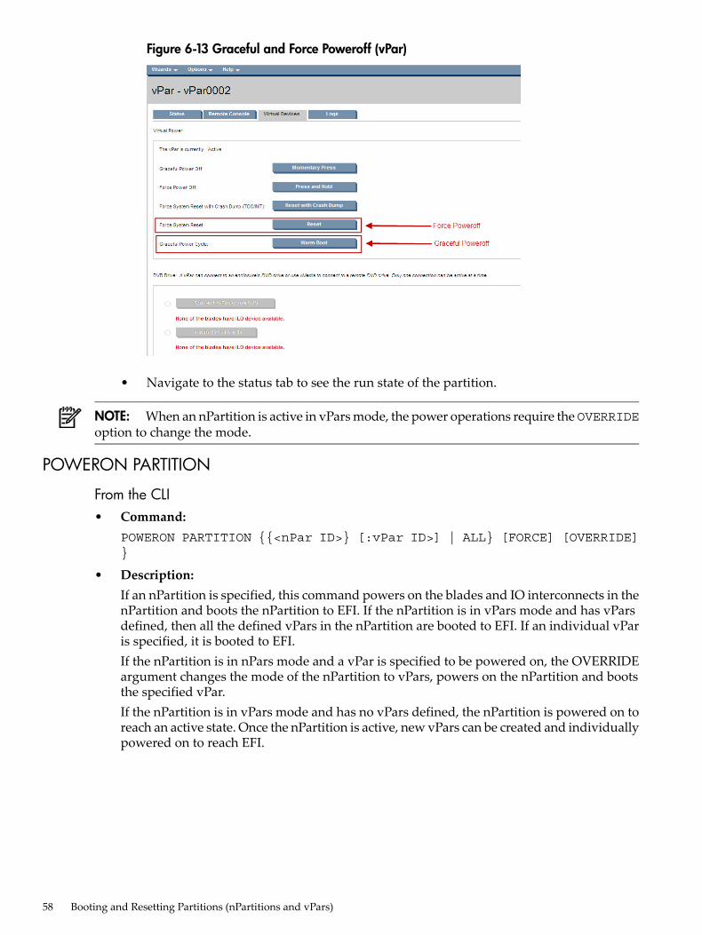
Figure 6-13 Graceful and Force Poweroff (vPar)
• Navigate to the status tab to see the run state of the partition.
NOTE: When an nPartition is active in vPars mode, the power operations require the OVERRIDEoption to change the mode.
POWERON PARTITION
From the CLI• Command:
POWERON PARTITION {{<nPar ID>} [:vPar ID>] | ALL} [FORCE] [OVERRIDE]}
• Description:If an nPartition is specified, this command powers on the blades and IO interconnects in thenPartition and boots the nPartition to EFI. If the nPartition is in vPars mode and has vParsdefined, then all the defined vPars in the nPartition are booted to EFI. If an individual vParis specified, it is booted to EFI.If the nPartition is in nPars mode and a vPar is specified to be powered on, the OVERRIDEargument changes the mode of the nPartition to vPars, powers on the nPartition and bootsthe specified vPar.If the nPartition is in vPars mode and has no vPars defined, the nPartition is powered on toreach an active state. Once the nPartition is active, new vPars can be created and individuallypowered on to reach EFI.
58 Booting and Resetting Partitions (nPartitions and vPars)

NOTE: If the EFI settings have been changed in the boot manager, the partition mayautomatically boot all the way to the OS login prompt.
• Access level/Bay level:OA Administrator, OA Operator
• Restriction:You must be connected to the monarch OA.
From the GUIFor information to poweron a partition using the GUI, see “Booting from the GUI”
REBOOT PARTITION
From the CLI• Command:
REBOOT PARTITION {{<nPar ID>} [:vPar ID>] | ALL} [FORCE] [OVERRIDE]}
• Description:Reboots the OS on the specified nPartition or virtual partition.The FORCE argument ungracefully reboots the OS in the specified partition. If the partitionis booted to EFI, then FORCE is required.The OVERRIDE argument reboots all virtual partitions on the specified nPartition.
• Access level/Bay level:OA Administrator, OA Operator
• Restriction:You must be connected to the monarch OA.
From the GUIFor information on rebooting the partition, see “From the GUI”
SET PARTITION DVD
From the CLI• Command:
SET PARTITION DVD {CONNECT | DISCONNECT}{{<nPar ID>} [:vPar ID>]}
• Description:Connect or disconnect the DVD module to the specified partition.
Task Summaries for Rebooting and Resetting Partitions 59

IMPORTANT: Before connecting a DVD to a virtual partition, the iLO rootport (or ioslot)from any of the blades in the nPartition must be assigned to the target virtual partition.
NOTE: The DVD module is disconnected from a partition when the partition is shutdownor rebooted. The DVD module may only be connected to a partition if there is a disk in thedrive.
• Access level/Bay level:OA Administrator, OA Operator
• Restriction:You must be connected to the monarch OA.
From the GUIThe Virtual Media (vMedia) feature provides a virtual floppy disk, USB Key, or DVD. This allowsan HP Superdome 2 partition to boot and use standard media on the network to which the iLOon a blade is connected. vMedia is also the mechanism used to give partitions access to theenclosure DVD drive.To connect to the enclosure DVD drive, the partition should be active. Select the Virtual Devicestab and click on the Connect to Enclosure DVD button.
Figure 6-14 SET Partition DVD for an nPartition
60 Booting and Resetting Partitions (nPartitions and vPars)

Figure 6-15 SET Partition DVD for vPar
NOTE: After you insert the DVD, the Connect to Enclosure DVD button is enabled.
OrSelect Launch Virtual Media. Figure 6-16 “Virtual Media Screen” shows the Launch VirtualMedia button and the Virtual Media screen.
Figure 6-16 Virtual Media Screen
Task Summaries for Rebooting and Resetting Partitions 61

SHOW PARTITION DVD
From the CLI• Command:
SHOW PARTITION DVD {{<nPar ID>} [:vPar ID>]}
• Description:Displays information about the DVD drive attached to the specified partition.
• Access level/Bay level:OA Administrator, OA Operator
• Restriction:You must be connected to the monarch OA.
From the GUITo get information about any DVDs or vMedia that is attached to a partition, go to that partition'spage, and select the Virtual Devices tab.
Figure 6-17 SHOW Partition DVD for an nPartition
62 Booting and Resetting Partitions (nPartitions and vPars)

Figure 6-18 SHOW Partition DVD for vPar
SHOW PARTITION INFO• Command:
SHOW PARTITION INFO {{<nPar ID>} [:vPar ID>]|ALL}
• Description:Displays information about the specified partition(s).
• Access level/Bay level:OA Administrator, OA Operator
• Restriction:You must be connected to the monarch OA.
Force System Reset and Crash Dump (TOC) PARTITION
From the CLI• Command:
TOC PARTITION {<nPar ID>} [:vPar ID>]|[OVERRIDE]
• Description:Performs a transfer-of-control reset of the specified nPartition or virtual partition. TheOVERRIDE argument TOC resets all virtual partitions on the specified nPartition.
• Access level/Bay level:OA Administrator, OA Operator
• Restriction:You must be connected to the monarch OA.
From the GUIFrom the Virtual Devices tab of the partition's page click on the Reset with Crash Dump button.
Task Summaries for Rebooting and Resetting Partitions 63

Figure 6-19 TOC nPartition
Figure 6-20 TOC vPar
64 Booting and Resetting Partitions (nPartitions and vPars)
UPDATE NPARTITION
IMPORTANT: This command is not available if you have complex firmware earlier than theOnline Firmware Update release.To update firmware for all partitions if you have complex firmware earlier than the OnlineFirmware Update, see “UPDATE FIRMWARE”.
• Command:UPDATE NPARTITION {{<nPar ID>} |ALL } {<uri>} [FORCE] [REINSTALL][NOEXECUTE]
• Description:— The UPDATE NPARTITION command downloads a new flash image from the network
or a USB drive attached to the DVD module, or a DVD in the enclosure DVD drive inthe monarch enclosure and uses it to update the firmware for HP Superdome 2 cellblades within the specified partition(s).
— The <uri> should be formatted as usb://<path> for USB installations. Use the SHOWUSBKEY command to obtain the <path>.
— Supported protocols for network installations are HTTPS, HTTP, TFTP, and FTP.— The <uri> should be formatted as protocol://host/path/filename for network
installations.— If your ftp server does not support anonymous logins, a username and password can
be specified within the <uri> with the following format:ftp://username:password@host/path/filename.
— The FORCE argument is required to install a firmware bundle that is a lower revisionlevel than what is currently installed on the partition(s).
— The REINSTALL argument forces the system to update the firmware of the specifiedpartition(s) regardless of current firmware revision.
— The NOEXECUTE argument causes the command to stop without updating firmware.• Access level/Bay level:
OA Administrator, OA Operator
• Restriction:You must be connected to the monarch OA.
UPDATE SHOW NPARTITION
CLI• Command:
UPDATE SHOW NPARTITION {<nPar ID>} |ALL }
• Description:Displays the version of the firmware bundle currently installed on the server blades withinthe specified partition(s).
• Access level/Bay level:All
• Restriction:None
Task Summaries for Rebooting and Resetting Partitions 65

GUITo view Firmware Summary information, click the Firmware Summary link.
Figure 6-21 Firmware Summary Information
UPDATE FIRMWARE
CLI• Command:
UPDATE FIRMWARE { <uri> } [ FORCE ] [ REINSTALL ] [ ALL ]
• Description:Updates the Superdome system's firmware (except I/O firmware)
• Access level/Bay level:OA Administrator, OA Operator
• Restriction:You must be connected to the monarch OA.
UPDATE SHOW FIRMWARE
CLI• Command:
UPDATE SHOW { FIRMWARE | NPARTITION { nPar name or number | ALL }}
• Description:Displays the configured Superdome firmware version and lists any of the followingSuperdome 2 devices whose installed firmware version differs from the system's configuredfirmware version: blade, XFM, SIOX, OA, GPSM.
• Access level/Bay level:OA Administrator, OA Operator
• Restriction:You must be connected to the monarch OA.
GUITo view Firmware Summary information, click the Firmware Summary link.
66 Booting and Resetting Partitions (nPartitions and vPars)

Figure 6-22 Firmware Summary
HP Superdome 2 Boot SupportThis section provides details of the accessories supported by HP Superdome 2 for bootingpurposes.The only supported local disk is fibre channel – P2000 FC G3 array.• Up to 12 LFF or 24 SFF SAS HDDs per array (SATA is available but not supported)• Expandable up to 149 HDDs• Suggest dedicated (per partition) 15K drives in Raid 1 configuration for
performance/availability• Up to 512 LUNs supported per P2000 FC G3 array• P2000 FC G3 product options, HDD and RAID details in P2000 Fc G3 QuickSpec are available
at:http://h18004.www1.hp.com/products/quickspecs/13551_div/13551_div.HTML
Each partition (nPartition or vPar) requires dedicated boot path(s) and dedicated HBAs.• One dedicated FC HBA per partition – two dedicated FC HBA for Serviceguard• AD221A; AD222A; AD393A (Emulex 4Gb combo) at initial release• AH400A; AH401A (QLogic 8GB 1- 2-port HBA) at initial release• AH402A; AH403A (Emulex 8GB 1- 2-port HBA) post initial releaseUp to 32 partitions per HP Superdome 2 – 16s. Each IOX supports up to 12 HBAs. Each HPSuperdome 2 – 16s supports up to 4 IOX at initial release.HP Superdome 2 partition limits:• nPartitions: per blade =1; per SD2-8s = 4; per SD2-16s = 8• vPars: per blade = 4; per SD2-8s = 16; per SD2-16s = 32; per nPartition = 16
Local BootUp to 4 boot paths are supported per P2000 FC G3 array.• P2000 FC G3 array can support up to two (2) dual port array controllers• Each controller supports up to two (2) 8GB FC links
HP Superdome 2 Boot Support 67

Considerations for Local Boot• Minimum configuration
— One P2000 FC G3 can handle up to 4 partitions— Boot paths are not redundant
◦ You must shutdown HP Superdome 2 to update P2000 FC G3 firmware.
• Optimal configuration— Create redundant boot paths to separate dual controllers on the P2000 FC G3
◦ Would support only two partitions per array
Boot from local SAN• HP Fibre Channel Switch(s)
— HP StorageWorks 8/24 Base SAN Switch (AM868A) is the default switch— 8GB switches recommended
• Considerations for Local SAN— Minimum configuration:
◦ For 16 or less partitions, one dual controller P2000 can be used— Optimal configuration (Redundant boot paths)
◦ Array needs to be configured to expose both P2000 controllers to the partitions toallow P2000 firmware updates
◦ The boot paths need to be in separate switches and P2000 controllers.◦ Dual path connectivity allows switch/array firmware updates without need to take
SD2 down◦ For more redundancy or >16 partitions a second P2000 can be used
Boot from External SANAn unlimited number of LUNs may be presented by an external SAN.Considerations for SAN boot• Dual paths to SAN/storage is recommended for all partitions
— Allows online updates of switch and array firmware• Two hops or less strongly recommended• No factory installation of operating environment
— nPartition and vPar definition is available and is independent of the installation of anoperating system.
nPartition and Resource Health StatusThe nPartition and resource status reveal the current health of the hardware. nPartition resources(blades and IObays) can have one of the following usage status:
DescriptionResource Usage
The slot has no resource.Empty
Resource is inactive.Inactive
Firmware is in the process of discovering/integrating theresource. It cannot be used for partition operations.
Un-integrated
The resource is active in the partition.Active
68 Booting and Resetting Partitions (nPartitions and vPars)
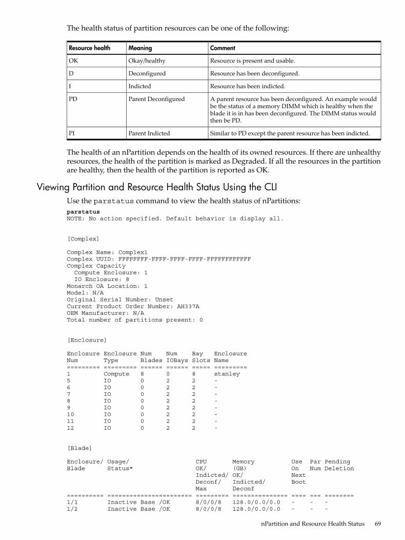
The health status of partition resources can be one of the following:
CommentMeaningResource health
Resource is present and usable.Okay/healthyOK
Resource has been deconfigured.DeconfiguredD
Resource has been indicted.IndictedI
A parent resource has been deconfigured. An example wouldbe the status of a memory DIMM which is healthy when theblade it is in has been deconfigured. The DIMM status wouldthen be PD.
Parent DeconfiguredPD
Similar to PD except the parent resource has been indicted.Parent IndictedPI
The health of an nPartition depends on the health of its owned resources. If there are unhealthyresources, the health of the partition is marked as Degraded. If all the resources in the partitionare healthy, then the health of the partition is reported as OK.
Viewing Partition and Resource Health Status Using the CLIUse the parstatus command to view the health status of nPartitions:parstatusNOTE: No action specified. Default behavior is display all.
[Complex]
Complex Name: Complex1Complex UUID: FFFFFFFF-FFFF-FFFF-FFFF-FFFFFFFFFFFFComplex Capacity Compute Enclosure: 1 IO Enclosure: 8Monarch OA Location: 1Model: N/AOriginal Serial Number: UnsetCurrent Product Order Number: AH337AOEM Manufacturer: N/ATotal number of partitions present: 0
[Enclosure]
Enclosure Enclosure Num Num Bay EnclosureNum Type Blades IOBays Slots Name========= ========= ====== ====== ===== =========1 Compute 8 0 8 stanley5 IO 0 2 2 -6 IO 0 2 2 -7 IO 0 2 2 -8 IO 0 2 2 -9 IO 0 2 2 -10 IO 0 2 2 -11 IO 0 2 2 -12 IO 0 2 2 -
[Blade]
Enclosure/ Usage/ CPU Memory Use Par PendingBlade Status* OK/ (GB) On Num Deletion Indicted/ OK/ Next Deconf/ Indicted/ Boot Max Deconf========== ======================= ========= =============== ==== === ========1/1 Inactive Base /OK 8/0/0/8 128.0/0.0/0.0 - - -1/2 Inactive Base /OK 8/0/0/8 128.0/0.0/0.0 - - -
nPartition and Resource Health Status 69

1/3 Inactive Base /OK 8/0/0/8 128.0/0.0/0.0 - - -1/4 Inactive Base /OK 8/0/0/8 128.0/0.0/0.0 - - -1/5 Inactive Base /OK 8/0/0/8 128.0/0.0/0.0 - - -1/6 Inactive Base /OK 8/0/0/8 128.0/0.0/0.0 - - -1/7 Inactive Base /OK 8/0/0/8 128.0/0.0/0.0 - - -1/8 Inactive Base /OK 8/0/0/8 128.0/0.0/0.0 - - -
* D-Deconfigured I-Indicted
[IOBay]
Enclosure/ Usage/ Par PendingIOBay Status* Num Deletion========== ======================= === ========5/1 Inactive /OK - -5/2 Inactive /OK - -6/1 Inactive /OK - -6/2 Inactive /OK - -7/1 Inactive /OK - -7/2 Inactive /OK - -8/1 Inactive /OK - -8/2 Inactive /OK - -9/1 Empty /Invalid - -9/2 Empty /Invalid - -10/1 Empty /Invalid - -10/2 Empty /Invalid - -11/1 Empty /Invalid - -11/2 Empty /Invalid - -12/1 Empty /Invalid - -12/2 Empty /Invalid - -
* D-Deconfigured I-Indicted
[Partition]
Par State/ Status* # of # of ILM/ Partition NameNum RunState Blades IOBays SLM (first 15 (GB)** characters)=== ======================= ======= ====== ====== ============= ===============
* D-Degraded** Actual allocated for Active and User requested for Inactive partitions
Viewing Partition and Resource Health Status Using the OA GUITo view the partition and resource health status using the OA GUI, select the nPartition fromthe left navigation pane. In the Status tab, the health status is shown as displayed inFigure 6-23 “nPartition Health Status”.
70 Booting and Resetting Partitions (nPartitions and vPars)

Figure 6-23 nPartition Health Status
Resource health policyResource health or status will be checked by Partition management subsystem before activatinga resource in a partition, be it an nPartition or vPar. Unhealthy resources are not activated aspart of activation of a partition.For an nPartition, blades and I/O bays are activated only if they are reported as healthy by theHealth management subsystem on the OA. Additionally, there is also a user specified attribute“failure_usage” for a blade and I/O bay which can be set to indicate whether the partition towhich the blade is assigned should be activated or not if the blade is found faulty. If the nPartitioncan be activated, the unhealthy resource is excluded before activating the nPartition. The settingof this attribute (failure_usage) can be done either during partition creation time, or modifiedlater using parmodify.For sub-blade resources, like cpu-cores, memory and root ports, the partition (nPartition or vPar)is always activated with the subset of healthy resources.An indicted resource is not considered unhealthy. Only deconfigured (or marked fordeconfiguration) resources are considered unhealthy. A resource is also considered unhealthyif its parent is reported as unhealthy.
nPartition and Resource Health Status 71

72

7 Planning Your System for Virtual PartitionsPlanning Your Virtual Partitions
Virtual Partition or vPars are created by specifying the resources are needed for the vPar.Resources that can be assigned to a vPar are:1. CPU-cores - either by specifying the number of CPU-cores that are part of the vPar or by
specifying the resource paths of individual CPU-cores or by specifying the socket resourcepaths and quantity from where the CPUs to be assigned.
2. Memory - Memory is specified by size or by specifying the socket resource path and size ofthe memory to be assigned.
3. I/O - I/O may be designated by either its rootport or IO slot resource path. These rootportsor IO slots are where the storage or networking devices are attached.
Before planning virtual partitions, collect the required hardware information about vPar assignableresources. This can typically be done using parstatus command from the OA and/or usingioscan if you have booted HP-UX in the nPar. If the nPartition is powered on in vPars mode,then vparstatus -A can also be used to get the available vPar assignable resources.
Virtual Partitions Layout PlanBefore you create vPars, you should have a plan of how you want to configure the virtualpartitions within your server.
Virtual Partition NamesA vPar name must at least have one of the following non-numeric characters: a-z, A-Z, dash (-),underscore (_), or period (.). No other non-numeric characters are allowed in a vPar name. Themaximum length of a vPar name is 254 characters. If the name is not specified either throughthe -p or -P options, a default name in the format vParNNNN is given to the vPar.Although the underscore (_) is a legal character within the name of a virtual partition, it is nota legal character within the Domain Name System (DNS), thus making it inappropriate if youwish your vPar names to match your OS hostnames.
Minimal Hardware ConfigurationEvery bootable virtual partition must have at least:• 1 CPU-core
On HP Integrity Superdome 2, by default, a vPar is created with zero CPU-cores. Such avPar cannot boot. So, for a bootable partition on Superdome 2, at least one CPU—core isrequired.
• System memory (sufficient for HP-UX and the applications in that partition)• A boot disk (when using a mass storage unit, check your hardware manual to verify that it
can support a boot disk)Although not required for booting a virtual partition, you can add LAN card(s) as required fornetworking.For your virtual partitions, use the number of CPUs, amount of memory, boot disk configuration,and LAN cards as is appropriate for your OS and applications.
Planning Your Virtual Partitions 73

CPU-core
NOTE:Processor Terminology Processing resources under vPars, both as input arguments and commandoutputs, are described as “CPU-cores.” The term “processor” refers to the hardware componentthat plugs into a processor socket. Therefore a single processor can have more than one core,and vPars commands will refer to the CPU-core with its resource path.Two vPars terms pre-date multi-core processors, so they are exceptions to this terminology:• “Boot processor,” which refers to the CPU—core on which the OS kernel of the virtual
partition was booted.• “Socket local processor (SLP),” which refers to a CPU-core in a specified socket on a specified
blade.
CPU-core: Boot Processor DefinitionsThe Boot Processor is the CPU—core on which the OS kernel of the virtual partition was booted.There is one boot processor per virtual partition.
CPU-core: Specifying Min and Max LimitsThe syntax to specify min and max CPUs assigned to a virtual partition is:-a, -m cpu:::[min]:[max]
where:-a adds resources to a virtual partition.-m modifies existing resources in a virtual partition.min is the minimum number of CPUs for the virtual partition to boot and the minimum number
of CPUs that must remain assigned to the partitionmax is the maximum number of CPUs that can be assigned to the virtual partition
NOTE: On a HP Integrity Superdome 2, a vPar is created with zero CPUs by default. Thereforethe default cpu:::[min] value is zero.The virtual partition must be in the down state to set the min or max value.The total count of CPUs in the virtual partition must always be greater than or equal to min andless than or equal to max.
Examples
• To set the minimum number of CPUs to 2:vparmodify -N <nPar name> -m cpu:::2
• To set the minimum number of CPUs to 2 and the maximum to 4:vparmodify -N <nPar name> -m cpu:::2:4
CPU-core: Adding and Deleting by Total
NOTE: Any modification to a vPar can be done only when the vPar is in the “Down” state.
The basic syntax for adding and deleting CPUs is:-a, -d, -m cpu::num
where:-a, -d, -m specifies adding, deleting, or modifying the total count of CPUs
74 Planning Your System for Virtual Partitions

num specifies the number of CPUs
NOTE:• -d cpu::num syntax (deletion by total), or• —d cpu:hw_path syntax (deletion by resource path)A virtual partition has to be down to add or delete CPUs.Deletion by total (cpu::num) is required when cores that were assigned by total are to be deleted.Deletion by path is required when cores added by path are to be deleted.Total increases or decreases by num when using the -a or -d options and is set to num whenusing the -m option.
vparcreate
With the vparcreate command, you would use the -a option and specify as num the numberof CPUs to allocate to the virtual partition.If no cpu syntax is given on the vparcreate command line, the default value for total cpu is0.
Example
• To create a virtual partition with 3 CPUs, set num to 3:vparcreate -N nParID -p vParID -a cpu::3
orvparcreate -p nparID:vParID -a cpu::3
vparmodify
With the vparmodify command, you can use the:• -a option to add num CPUs to the virtual partition,• -d option to delete num CPUs from the virtual partition,• -m option to modify (set) to num the number of CPUs assigned to the partition.
Examples
• If an existing partition has 2 CPUs and you would like to set the number of CPUs to 3, youcan modify the number of CPUs assigned to the partition by using the -m option and settingnum to 3:vparmodify -N nPar0001 -p vPar0001 -m cpu::3
To set the number of CPUs back to two, use the -m option and set num to 2:vparmodify -N nPar0001 -p vPar0001 -m cpu::2
• If you would like to add 1 CPU—core to an existing partition, regardless of its currentCPU—core count, you can add 1 CPU—core by using the -a option and setting num to 1:vparmodify -N nPar0001 -p vPar0001 -a cpu::1
To remove the added CPU—core from the partition, use the -d option and set num to 1:vparmodify -N nPar0001 -p vPar0001 -d cpu::1
Planning Your Virtual Partitions 75

CPU-core: Adding or Deleting by SLP (Socket Local Processor)Similar to SLM (socket local memory), SLP (Socket local processor) refers to CPUs in a specificsocket on a specific blade. This is generally used in conjunction with SLM to ensure that the coresand the memory are close to each other. The syntax to specify SLP is:-a, -d socket:socket_ID:cpu::num
where:-a is adding-d is deletingsocket_ID is the path (enclosure#/blade#/socket#)
num is the number of CPU-cores from the socket to be added to or deleted from thevirtual partition. Note that the num CPU-cores need to be available in the socketas well as in the nPartition before they can be added. To see whether they areavailable or already allocated, use the vparstatus -A command when thenPartition is booted in vPar mode.
Examples
• To create a virtual partition using 2 CPU-cores from socket 0 on blade 1:vparcreate -N <nPar name> -p <vPar name> -a socket:1/1/0:cpu::2
• To increase the number of CPU-cores by 2 using the CPU-cores from socket 0 on blade 1:vparmodify -N <nPar name> -p <vPar name> -a socket:1/1/0:cpu::2
To decrease the number of CPU-cores by 2 removing CPUs from socket 0 on blade 1:vparmodify -N <nPar name> -p <vPar name> -d socket:1/1/0:cpu::2
CPU-core: Adding or Deleting by Resource pathThe syntax for specifying by resource path is:-a, -d cpu:cpu_path
where:-a is adding-d is deletingcpu_path is the resource path of the cpu (you can find the resource path of an already existing
and defined vPar using the vparstatus -v -p <nPar_id:vPar_id>)command.
NOTE: CPUs that are added using the resource path syntax can be deleted only by using theresource path syntax.Adding or deleting CPUs by path changes the total count of CPUs.
Example
• To add the CPU at1/1/0/0 (enclosure 1, blade1, socket 0, core 0) and1/1/0/1 to vPar0001:vparmodify -N <nPar name> -p <vPar name> -a cpu:1/1/0/0 -acpu:1/1/0/1
CPU: Summary InformationImpact on vPars Commands: Specifying CPUThe CPU resource paths can be defined in the following four ways:
76 Planning Your System for Virtual Partitions
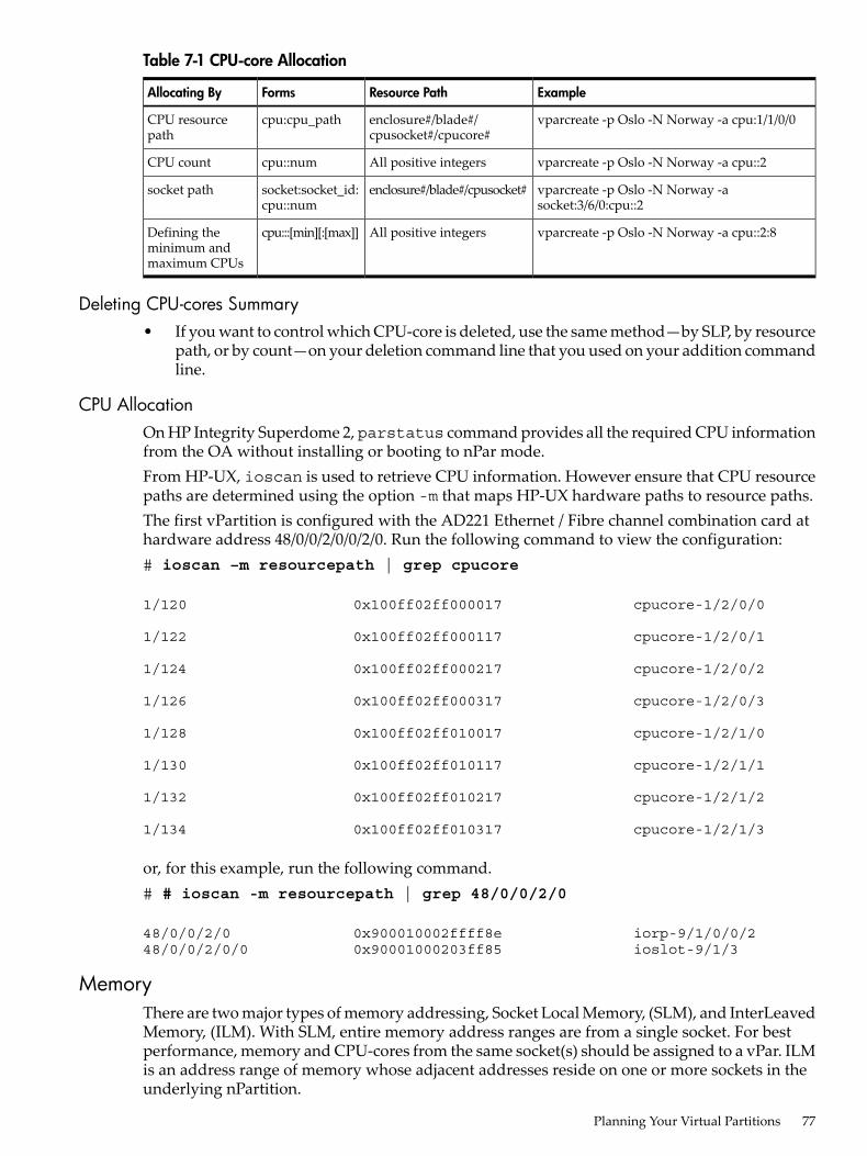
Table 7-1 CPU-core Allocation
ExampleResource PathFormsAllocating By
vparcreate -p Oslo -N Norway -a cpu:1/1/0/0enclosure#/blade#/cpusocket#/cpucore#
cpu:cpu_pathCPU resourcepath
vparcreate -p Oslo -N Norway -a cpu::2All positive integerscpu::numCPU count
vparcreate -p Oslo -N Norway -asocket:3/6/0:cpu::2
enclosure#/blade#/cpusocket#socket:socket_id:cpu::num
socket path
vparcreate -p Oslo -N Norway -a cpu::2:8All positive integerscpu:::[min][:[max]]Defining theminimum andmaximum CPUs
Deleting CPU-cores Summary• If you want to control which CPU-core is deleted, use the same method—by SLP, by resource
path, or by count—on your deletion command line that you used on your addition commandline.
CPU AllocationOn HP Integrity Superdome 2, parstatus command provides all the required CPU informationfrom the OA without installing or booting to nPar mode.From HP-UX, ioscan is used to retrieve CPU information. However ensure that CPU resourcepaths are determined using the option -m that maps HP-UX hardware paths to resource paths.The first vPartition is configured with the AD221 Ethernet / Fibre channel combination card athardware address 48/0/0/2/0/0/2/0. Run the following command to view the configuration:# ioscan –m resourcepath | grep cpucore
1/120 0x100ff02ff000017 cpucore-1/2/0/0
1/122 0x100ff02ff000117 cpucore-1/2/0/1
1/124 0x100ff02ff000217 cpucore-1/2/0/2
1/126 0x100ff02ff000317 cpucore-1/2/0/3
1/128 0x100ff02ff010017 cpucore-1/2/1/0
1/130 0x100ff02ff010117 cpucore-1/2/1/1
1/132 0x100ff02ff010217 cpucore-1/2/1/2
1/134 0x100ff02ff010317 cpucore-1/2/1/3
or, for this example, run the following command.# # ioscan -m resourcepath | grep 48/0/0/2/0
48/0/0/2/0 0x900010002ffff8e iorp-9/1/0/0/248/0/0/2/0/0 0x90001000203ff85 ioslot-9/1/3
MemoryThere are two major types of memory addressing, Socket Local Memory, (SLM), and InterLeavedMemory, (ILM). With SLM, entire memory address ranges are from a single socket. For bestperformance, memory and CPU-cores from the same socket(s) should be assigned to a vPar. ILMis an address range of memory whose adjacent addresses reside on one or more sockets in theunderlying nPartition.
Planning Your Virtual Partitions 77

Memory GranularityThe nPartition memory is divided into multiple memory granules by firmware for ease of memoryassignment to vPars. The size of these memory granules can be optionally specified by the user.Memory granularity refers to the size of these memory granules. Note that memory granulesare not the actual memory DIMMs.The granularity for SLM and ILM are specified separately by the user. However, the followingapplies to both types of memory:• Memory granularity is specified at nPartition creation time. Any modification thereafter
requires a reboot of the nPartition.• The minimum values (ILM and SLM granularity) are 256 MB.• The default value is OS dependent and may be adjusted based on the total memory available
in the nPartition.• Memory is assigned to virtual partitions in multiples of granule sizes.HP recommends not to change the default memory granularity value chosen by the system,unless there is a specific need to do that.
Assigning Memory to a vPar• The -a mem::size option is used to assign size megabytes of ILM to a vPar.• The -a socket:socket_id:mem::size option assigns size megabytes of SLM from
socket socket_id to a vPar.If size is not an integral multiple of the granularity of the specified memory type, vPars normallyadjusts it upward to the next granule boundary.In a vPar environment, either of the above command line options will cause the system to reservethe indicated memory, if it is available. Thus, it is possible to define vPars with more memoryin them than is in the entire nPartition. Actual memory ranges are only assigned to the vParwhen it is booted. These ranges may be different from boot to boot.
I/OThe vPar assignable IO resources are rootports or ioslots in the blades and I/O bays. Rootportsand ioslots are two different ways of representing I/O resources. The parstatus -cenclosure#/blade# -V command provides the rootport to ioslot mapping for the I/O resourceson a blade. Similarly, the parstatus -i IOX#/IObay# -V command provides the rootportto ioslot mapping for the I/O resources in an I/O bay. Rootports and ioslots have a one-to-onemapping and either of them can be assigned to a vPar. The rootport (RP) or ioslot is specified inthe resource path format. Typically disk devices or LAN devices get attached to a rootport. Onblades, iLO is also off a rootport. There is a one-to-one mapping between the rootport and theI/O slot on HP Integrity Superdome 2 servers.
Assigning I/O at the rootport or I/O slot LevelYou can run the vparcreate and vparmodify commands with either of these parameters:rootport resourcepath format: -a io:9/1/0/0/2orioslot resource path format: -a ioslot:9/1/3A vPartition may be created at the OA with the following command:vparcreate -N5 –p1 -a cpu::4 -a mem::6000 -a ioslot:9/1/3
To verify that the resulting vPartition had the expected IO in that slot, install and boot HP-UXin that partition and then run ioscan -m resourcepath, searching for the ioslot number:# ioscan -m resourcepath | grep 9/1/3
78 Planning Your System for Virtual Partitions

48/0/0/2/0/0 0x90001000203ff85 ioslot-9/1/3
This result is used in a second call to ioscan to get the IO details:# ioscan -kf -H 48/0/0/2/0 Class I H/W Path Driver S/W State H/W Type Description============================================================================ba 30 48/0/0/2/0 PCItoPCI CLAIMED BUS_NEXUS PCItoPCI Bridgeslot 18 48/0/0/2/0/0 pci_slot CLAIMED SLOT PCI Slotba 31 48/0/0/2/0/0/0 PCItoPCI CLAIMED BUS_NEXUS PCItoPCI Bridgeba 32 48/0/0/2/0/0/0/2/0 PCItoPCI CLAIMED BUS_NEXUS PCItoPCI Bridgelan 8 48/0/0/2/0/0/0/2/0/0/0 iether CLAIMED INTERFACE HP AD221-60001 PCIe 1000Base-T 4Gb FC/1000rba 33 48/0/0/2/0/0/0/4/0 PCItoPCI CLAIMED BUS_NEXUS PCItoPCI Bridgefc 0 48/0/0/2/0/0/0/4/0/0/0 fclp CLAIMED INTERFACE HP AD221-60001 PCIe Fibre Channel 1-port 4rfcp 0 48/0/0/2/0/0/0/4/0/0/0.25 fclp_fcp CLAIMED INTERFACE FCP Domainext_bus 1 48/0/0/2/0/0/0/4/0/0/0.25.0.0.0 fclp_vbus CLAIMED INTERFACE FCP Array Interfacetarget 1 48/0/0/2/0/0/0/4/0/0/0.25.0.0.0.0 tgt CLAIMED DEVICE ctl 1 48/0/0/2/0/0/0/4/0/0/0.25.0.0.0.0.0 sctl CLAIMED DEVICE HP MSA CONTROLLERdisk 0 48/0/0/2/0/0/0/4/0/0/0.25.0.0.0.0.1 sdisk CLAIMED DEVICE HP MSA VOLUMEdisk 1 48/0/0/2/0/0/0/4/0/0/0.25.0.0.0.0.2 sdisk CLAIMED DEVICE HP MSA VOLUMEdisk 2 48/0/0/2/0/0/0/4/0/0/0.25.0.0.0.0.3 sdisk CLAIMED DEVICE HP MSA VOLUMEdisk 3 48/0/0/2/0/0/0/4/0/0/0.25.0.0.0.0.4 sdisk CLAIMED DEVICE HP MSA VOLUMEdisk 4 48/0/0/2/0/0/0/4/0/0/0.25.0.0.0.0.5 sdisk CLAIMED DEVICE HP MSA VOLUMEdisk 5 48/0/0/2/0/0/0/4/0/0/0.25.0.0.0.0.6 sdisk CLAIMED DEVICE HP MSA VOLUMEdisk 6 48/0/0/2/0/0/0/4/0/0/0.25.0.0.0.0.7 sdisk CLAIMED DEVICE HP MSA VOLUMEtarget 2 48/0/0/2/0/0/0/4/0/0/0.25.0.0.0.1 tgt CLAIMED DEVICE disk 7 48/0/0/2/0/0/0/4/0/0/0.25.0.0.0.1.0 sdisk CLAIMED DEVICE HP MSA VOLUMEdisk 8 48/0/0/2/0/0/0/4/0/0/0.25.0.0.0.1.1 sdisk CLAIMED DEVICE HP MSA VOLUMEdisk 9 48/0/0/2/0/0/0/4/0/0/0.25.0.0.0.1.2 sdisk CLAIMED DEVICE HP MSA VOLUMEdisk 10 48/0/0/2/0/0/0/4/0/0/0.25.0.0.0.1.3 sdisk CLAIMED DEVICE HP MSA VOLUMEdisk 11 48/0/0/2/0/0/0/4/0/0/0.25.0.0.0.1.4 sdisk CLAIMED DEVICE HP MSA VOLUMEdisk 12 48/0/0/2/0/0/0/4/0/0/0.25.0.0.0.1.5 sdisk CLAIMED DEVICE HP MSA VOLUMEdisk 13 48/0/0/2/0/0/0/4/0/0/0.25.0.0.0.1.6 sdisk CLAIMED DEVICE HP MSA VOLUMEdisk 14 48/0/0/2/0/0/0/4/0/0/0.25.0.0.0.1.7 sdisk CLAIMED DEVICE HP MSA VOLUMEtarget 3 48/0/0/2/0/0/0/4/0/0/0.25.0.0.0.2 tgt CLAIMED DEVICE disk 15 48/0/0/2/0/0/0/4/0/0/0.25.0.0.0.2.0 sdisk CLAIMED DEVICE HP MSA VOLUMEdisk 16 48/0/0/2/0/0/0/4/0/0/0.25.0.0.0.2.1 sdisk CLAIMED DEVICE HP MSA VOLUMEdisk 17 48/0/0/2/0/0/0/4/0/0/0.25.0.0.0.2.2 sdisk CLAIMED DEVICE HP MSA VOLUMEdisk 18 48/0/0/2/0/0/0/4/0/0/0.25.0.0.0.2.3 sdisk CLAIMED DEVICE HP MSA VOLUMEdisk 19 48/0/0/2/0/0/0/4/0/0/0.25.0.0.0.2.4 sdisk CLAIMED DEVICE HP MSA VOLUMEdisk 20 48/0/0/2/0/0/0/4/0/0/0.25.0.0.0.2.5 sdisk CLAIMED DEVICE HP MSA VOLUMEdisk 21 48/0/0/2/0/0/0/4/0/0/0.25.0.0.0.2.6 sdisk CLAIMED DEVICE HP MSA VOLUMEext_bus 0 48/0/0/2/0/0/0/4/0/0/0.25.0.255.0 fclp_vbus CLAIMED INTERFACE FCP Device Interfacetarget 0 48/0/0/2/0/0/0/4/0/0/0.25.0.255.0.0 tgt CLAIMED DEVICE ctl 0 48/0/0/2/0/0/0/4/0/0/0.25.0.255.0.0.0 sctl CLAIMED DEVICE HP MSA CONTROLLER
The rootport is associated with the I/O slot hosting the PCIe port. The table below displays theI/O hierarchy:
Table 7-2 Assigning I/O Resources
Long FormMediumForm
ShortFormResource PathResourcesI/O
enclosure3/blade6/iohub0/iorc1/iorp2iorp-3/6/0/1/23/6/0/1/2blade_enclosure/blade/iohub/rootcomplex/rootport
BladeRootport
enclosure7/iobay1/iohub0/iorc1/iorp2iorp-7/1/0/1/27/1/0/1/2io_enclosure/iobay/iohub/rootcomplex/rootport
I/OBay
enclosure3/blade6/ioslot5ioslot-3/6/53/6/5blade_enclosure#/blade#/ioslot#BladeI/O Slot
enclosure7/iobay1/ioslot4ioslot-7/1/47/1/4IO_enclosure#/iobay#/ioslot#I/OBay
Syntax, Rules, and NotesWhen a virtual partition is down, vparstatus does not show any CPU-core assigned as theboot processor. The boot processor is not assigned until the virtual partition is actually booted.The following table lists the summary of resource syntax forms.
Planning Your Virtual Partitions 79

Table 7-3 Resource syntax summary
# times/commandOptionsFormsResource
Multiple-a, -dcpu:cpu_pathCPU
Once-a, -m, -dcpu::num
Once-mcpu:::{min}:{max}
Once per socket_id-a, -d, -msocket:socket_id:cpu::num
-- or --
Multiple-a, -dcore:core_path
Once-a, -d, -mcore::num
Once-mcore:::{min}:{max}
Once per socket_id-a, -d, -msocket:socket_id:core::num
Multiple-a, -d, -mio:io_pathI/O
Multiple-a, -d, -mioslot:ioslot_path
Once-a, -d, -mmem::ilm_sizeMemory
Once per socket_id-a, -d, -msocket:socket_id:mem::slm_size
Counts Summary• At all times, the rule of min<=total<=max is enforced.• The first field is always one of the (case-insensitive) strings: cpu, core, io, ioslot, mem, or
socket.• num, min, and max are all positive integers.
Parspec change policyThe “parspec change policy” is an attribute of an nPar which the user can enable or disable. Bydefault, it is enabled. The parspec change policy determines whether the OA can automaticallymodify a parspec in order to enable a partition operation (such as booting). In some scenarios,it is possible that the system cannot meet the customer requested resource or attributespecifications in the parspec for an nPar or vPar. This could be due to non-existent resources ordegraded resources or other restrictions in hardware architecture. Under these circumstances,the partition configuration in the parspec may need to be modified to make forward progress.The parspec change policy attribute of the nPar gives the customer the ability to choose thebehavior in these cases. If the parspec change policy is enabled (default), the affected partitionoperation is continued with available or modified resources or attributes after making the requiredchanges in the parspec. If the parspec change policy is disabled, the affected partition operationis failed and no changes are made to the parspec.For example, consider the scenario where the memory granularity specified by the user cannotbe accommodated by the system and a new memory granularity value has to be applied. Thisis likely to affect the vPar memory sizes specified by the user and stored in the parspec sincethey will have to be rounded up to be a multiple of the new memory granularity. Users maywant to make vPar memory size adjustments manually and not have the system make anychanges in the vPar memory sizes they have assigned. In that case, they would have to disablethe parspec change policy for the nPar before they configure and boot vPars.
A note on DeconfigurationOn a vPars system, when a virtual partition with parspec change policy disabled goes down andcontains a deconfigured or deactivated CPU, the partition controller on the OA will try to
80 Planning Your System for Virtual Partitions

decommission the CPU from use and replace it with another good CPU if possible. If this is notpossible, the partition controller will not allow the partition to boot until the user modifies thevPar configuration to use the available healthy CPU-cores. The following are some of the caseswhere the partition controller may not allow the when parspec change policy is disabled:• There is a deconfigured or deactivated CPU which has been reserved for the partition as
part of the total (cpu::num) request and partition controller does not have any free CPUswith which to replace it. To correct this, you can delete CPUs from other partitions or fromthis partition.
• There is a deconfigured or deactivated CPU that has been bound to the partition by resourcepath (cpu:hw_path). Partition Controller does not try to replace a CPU-core assigned to avPar by resource path. To correct this, you can remove the CPU specified by resource pathusing vparmodify -d cpu:resourcepath to allow the deconfigured or deactivated CPU tobe decommissioned. Add a different CPU to vPar using vparmodify if needed.
• There is a deconfigured CPU which has been reserved for the partition as part of a SLPrequest (socket id:cpu::num) and there are no free SLPs in that socket. To correct this, youcan make available CPUs from that socket by deleting the CPUs that are part of this socketfrom other partitions or delete the CPUs from the socket in this partition.
If the parspec change policy is enabled (default), then the partition is booted with existingresources and the parspec is modified to delete the deconfigured resource. Please note that youwill need to manually add back the resource using vparmodify command when the resource ishealthy and available for use.Example• A cpu, 1/1/0/0, is added by path to a vPar with total 4 cpus.• The cpu gets deconfigured because of an error on the next boot of the vPar.• If parspec change policy is enabled, the vPar will boot without 1/1/0/0 and with the remainin
3 cpus that are part of the partition, and the parspec will be modified to delete 1/1/0/0• The cpu might be acquitted by the health subsystem at a later point or the blade containing
the cpu may be replaced. So, the CPU is now available, but is not automatically added backto the vPar. The vPar will continue to boot with 3 cpus, until the user does a vparmodifyand adds back the same cpu or another cpu by count.
Planning Your Virtual Partitions 81

82

8 Managing and Booting Virtual PartitionsThis chapter covers:• Switching Modes• Managing the Virtual Partitions
— Creating a Virtual Partition— Booting a Virtual Partition— Modifying a Virtual Partition— Virtual Partition States— Shutting Down or Rebooting a Virtual Partition— When to Shutdown All Virtual Partitions— Removing a Virtual Partition
Modes: Switching between nPars and vPars Modes
ModesThemode can be set for an nPartition during creation time using the parcreate or the parmodifycommand. Mode switching can thus be performed from the OA CLI. For vPars usage, thereare only two modes:• vPars
Sets the next nPartition boot to boot into the vPars environment. This allows you to bootinto vPars mode and hence boot all the virtual partitions in the nPartition.
• nPars
Sets the next nPartition boot to boot into the standalone environment. In this mode, youcannot boot the virtual partitions. However, you can boot any OE instance into standalonemode. For an nPartition that is already inactive, mode switch happens when the inactivenPartition is booted.
Modes: Switching between nPars and vPars Modes 83

Setting the Mode• parmodify [-N] next_boot_mode
where:next_boot_mode has the value of either vPars or nParsSpecifies whether the nPartition has to be booted as a single partition (nPars mode) capableof running only a single operating system (OS) instance or as one or more virtual partitions(vPars mode) as defined in the virtual partition database in the partition specification, eachcapable of running its own OS instance.
Booting from the CLITo set the nPartition into vPars mode so that the next nPartition boot allows you to bootinto vPars mode and therefore the vPars environment:1. Set the mode
# parmodify –p <npar_name> -N vpars
2. After the nPartition is set in vPar mode, the vPar needs to be activatedpoweron partition {nPartition identifier}[:{vPar identifier}] (Notspecifying a vPar will result in all of the vPars in the nPartition to be booted.)ORUse the pe command to prompt you for the partition to activate:
Example 8-1 Booting a vPar
pe
This command controls power enable to a partition.
Partition Partition Number Name --------- --------- 1 nPar0001 2 nPar0002 2:1 nPar0002:vPar0001 Q) Quit
Select partition number: 2:1
The power state is OFF for partition 2:1. In what state do you want the power? (ON/OFF) on
Booting from the GUIIn the OA GUI, using the left navigation pane, go to the vPar's partition status page. Click onthe Virtual Devices tab:
84 Managing and Booting Virtual Partitions

Figure 8-1 Virtual Device
Getting the vPar ConsoleA virtual partition’s system console may be accessed by either the command line or the GUI.
From the CLI
Use the co command with or without the partition id.
Example 8-2 Example
co
Partition Partition Number Name --------- --------- 1 nPar0001 2 nPar0002 2:1 nPar0002:vPar0001 Q) Quit Select partition number: 2:1----Log Snippet-------------Log Snippet--------- Welcome to the Superdome 2 console <use <Ctrl-b> to exit.>Shell>
From the GUI
On the OA Administrator, you can access console from each partition’s details page. Click onthe Remote Console tab:
Figure 8-2 Remote Console
Modes: Switching between nPars and vPars Modes 85

NOTE: On HP Integrity Superdome 2, vpmon is not supported. Attempting to boot vpmonfrom the ISL prompt results in the following error message:ERROR:Unsupported boot enironment for vpar monitor! Booting vpmon not supported on thisplatform Resetting the system!
Managing: Creating a Virtual PartitionYou can create a virtual partition using the vparcreate command.Examples• In this example, we want to create a virtual partition (vPar0001) in the first nPartition
(nPar0001), with 6 cores, 4 gigabytes of RAM, and the HBA in IO extender 6, Bay 2, Slot 3.This is done from the OA command line with thevparcreate command. Since the commandis being issued outside of any nPar, either the option –N {nParID} or the vParID format of{nParID}:{vParID} is used. As with nPartitions, the ID may either be the partition name ornumber:vparcreate –N nPar0001 –p vPar0001 -a cpu::6 -a mem::4096 -aioslot:6/2/3
• In this example, we will create another virtual partition within the same nPartition, nPar0001,with 2 cores, 8 gigabytes of RAM, and the HBA in IO extender 6, Bay 2, Slot 4.vparcreate –N nPar0001 –p vPar0002
Use vparmodify command to assign the resources.vparmodify -p nPar0001:vPar0002 -a cpu::2 -a mem::8192 -aioslot:6/2/4
You can check the list of vPars and assigned resources by running the following command:vparstatus –N 1
[Virtual Partition]Num Name RunState State=== ========================== ============ =========1 vPar0001 DOWN Inactive2 vPar0002 DOWN Inactive
[Virtual Partition Resource Summary]Virtual Partition CPU Num Num Granularity Total MBNum Name Min/Max CPUs IO ILM SLM ILM SLM=== ========================== ======= ==== ==== ===== ===== ====== ======1 vPar0001 0/ 8 6 1 1024 1024 4096 02 vPar0002 0/ 8 2 1 1024 1024 8192 0
Booting a Virtual PartitionTo boot a virtual partition, use the poweron command. The virtual partition must exist and bein the DOWN RunState. (To shutdown a booted virtual partition, see “Shutting Down or Rebootinga Virtual Partition”).To boot the existing virtual partition vPar0001:poweron partition nPar0001:vPar0001
Alternatively, you may also use vparboot command to boot virtual partition.
Managing: Modifying Attributes of a Virtual PartitionYou can change a virtual partition’s name and its resource attributes via the vparmodifycommand. The virtual partition needs to be in Down state to modify it using vparmodify
86 Managing and Booting Virtual Partitions

command. See the vparmodify man page on the OS (or the vparmodify2 help on the OA) for moreinformation on the attributes.
Examples• To rename the virtual partition vPar0001 to Bergen:
vparmodify -N nPar0001 -p 1 -P Bergen
• To add two processors to the virtual partition Oslo (cpu and core syntax):vparmodify -N nPar0001 -p vPar0001 -a cpu::2
orvparmodify -N nPar0001 -p vPar0001 -a core::2
• To add two socket-local processors from enclosure 1, blade 2, socket 0 to the virtual partitionvPar0001 ((cpu and core syntax):vparmodify -N nPar0001 -p vPar0001 -a socket:1/2/0:cpu::2
orvparmodify -N nPar0001 -p vPar0001 -a socket:3/6/0:core::2
• To delete 1 GB of Socket Local Memory on enclosure 1, blade 2, socket 0 from the samevirtual partition:vparmodify -N nPar0001 -p vPar0001 -d socket:1/2/0:mem::1024
• To add the I/O card in IOX 6, I/O bay 2, slot 3 to the virtual partition (io and ioslotsyntax):vparmodify -N nPar0001 -p vPar0001 -a io:6/2/0/0/2
orvparmodify -N nPar0001 -p vPar0001 -a ioslot:6/2/3
Commands: Displaying vPars Resource Information (vparstatus)On HP Integrity Superdome 2, the Partition Controller running on the OA maintains all theinformation about the virtual partitions, including the current state of the virtual partitions andtheir resources. Using the OA command vparstatus, you can display this information. Thissection describes the possible virtual partition states and the common usages of the vparstatuscommand.
Virtual Partition StatesVirtual partitions can either be in active or inactive states. An inactive virtual partition will beable to boot up as a single operating system. The initiation of the boot operation changes thestate from inactive to active.
Table 8-1 Run-states of an inactive Virtual Partition
DescriptionState
The virtual partition is fully halted. This could be the result of a normal /etc/shutdown -hcommand, or after it has been created.
DOWN
This run-state is shown when a boot is initiated on a virtual partition. This normally results inthe virtual partition becoming active with a FWBOOT run-state.
ACTIVATING
This run-state is displayed while a shutdown/reboot of a virtual partition is being processed.DEACTIVATING1
This run-state is displayed while a reset of a virtual partition is being processed.RESETTING1
This run-state is displayed while an MCA of a virtual partition is being processed.MCA1
Commands: Displaying vPars Resource Information (vparstatus) 87

Table 8-1 Run-states of an inactive Virtual Partition (continued)
DescriptionState
The virtual partition definition exists in the current partition specification and the nPartitionis booted in nPars mode.
DEFINED
The virtual partition definition defined in an alternate partition specification.ALT_DEFINED
1 An inactive vPar can be in the DEACTIVATING, RESETTING or MCA RunStates, if it encounters an error or isinterrupted during the activation process.
Table 8-2 Run-states of an active Virtual Partition
DescriptionState
The virtual partition normally reaches this run-state from the ACTIVATING run-state whenthe virtual partition is marked as active. This is a transitional run-state and normally reachesEFI run-state.
FWBOOT
The virtual partition reaches this run-state after the firmware boot process launches the EFIshell.
EFI
The virtual partition reaches this run-state after the operation system is launched. This is atransitional run-state and normally reaches UP run-state.
OSBOOT
The virtual partition is in this run-state when the operating system is completely functional.UP
A shutdown/reboot/reset operation has been initiated on this partition.SHUT
This run-state is displayed while a shutdown/reboot of a virtual partition is being processed.DEACTIVATING
This run-state is displayed while a reset of a virtual partition is being processed.RESETTING
An MCA has occurred in the virtual partition and is being processed.MCA
This run-state is displayed when an INIT of a virtual partition is being processed.INIT
The virtual partition in an unknown (error) run-state.UNKNOWN
88 Managing and Booting Virtual Partitions

vparstatus: Summary InformationThe vparstatus command provies information regarding vPars and vPar assignable resources.As with the vparcreate and vparmodify commands, when invoked from the OA, it isnecessary to use the –N option to indicate which nPartition is to be looked at. (The virtual partitioncommands only work on one nPartition at a time.)
ExamplesThe following are some examples of displaying vparstatus summary information:• To display a summary format of all resources in virtual partition 1:1
vparstatus -p 1 -N 1[Virtual Partition]Num Name RunState State=== ========================== ============ =========1 vPar0001 DOWN Inactive[Virtual Partition Resource Summary]Virtual Partition CPU Num Num Granularity Total MBNum Name Min/Max CPUs IO ILM SLM ILM SLM=== ========================== ======= ==== ==== ===== ===== ====== ======1 vPar0001 0/ 8 6 1 1024 1024 4096 0
• To display the detailed attributes and resources of vpar1 in nPartition 1:vparstatus -v -p1:1[Virtual Partition Details]Number: 1Name: vPar0001RunState: DOWNState: Inactive[CPU Details]Min/Max: 0/8User assigned [Path]:Boot processor [Path]:System assigned [Path]:Non-socket-specific: User assigned [Count]: 0 System assigned [Count]: 6Socket-specific [Count]: Socket-ID/Count <none> [IO Details] [Root Port] [Slot] 6/2/0/0/2 6/2/3[Memory Details]ILM Total (MB): 4096ILM Granularity (MB): 1024SLM (Socket-ID MB):SLM Granularity (MB): 1024[Containing nPartition Details]nPartition number: 1nPartition name: nPar0001Current boot mode: vparsNext boot mode: vpars
• To display the detailed attributes and resources of vpar1 in machine-readable format:vparstatus -M -p1:1vPar0001;1:DOWN;Inactive::::0/8;;;;;0;6;:6/2/0/0/2;6/2/3:;4096;;;4096;1024;;;;1024:N/A;N/A;N/A:N:1;nPar0001;vpars;vpars
• To display CPU-core configuration information:vparstatus -d -N 1
CPU Config Assigned to Sibling Informationpath Status Num Name Path Num Name========= ====== === ==================== ========= === ====================1/2/0/0 OK - - 1/2/0/1 - -1/2/0/0 OK - - 1/2/0/2 - -1/2/0/0 OK - - 1/2/0/3 - -1/2/0/1 OK - - 1/2/0/0 - -
Commands: Displaying vPars Resource Information (vparstatus) 89

1/2/0/1 OK - - 1/2/0/2 - -1/2/0/1 OK - - 1/2/0/3 - -1/2/0/2 OK - - 1/2/0/0 - -1/2/0/2 OK - - 1/2/0/1 - -1/2/0/2 OK - - 1/2/0/3 - -1/2/0/3 OK - - 1/2/0/0 - -1/2/0/3 OK - - 1/2/0/1 - -1/2/0/3 OK - - 1/2/0/2 - -1/2/1/0 OK - - 1/2/1/1 - -1/2/1/0 OK - - 1/2/1/2 - -1/2/1/0 OK - - 1/2/1/3 - -1/2/1/1 OK - - 1/2/1/0 - -1/2/1/1 OK - - 1/2/1/2 - -1/2/1/1 OK - - 1/2/1/3 - -1/2/1/2 OK - - 1/2/1/0 - -1/2/1/2 OK - - 1/2/1/1 - -1/2/1/2 OK - - 1/2/1/3 - -1/2/1/3 OK - - 1/2/1/0 - -1/2/1/3 OK - - 1/2/1/1 - -1/2/1/3 OK - - 1/2/1/2 - -
• To display available resources in the nPartition:vparstatus -A -N 1[CPUs (path)]: 1/2/0/0 1/2/0/1 1/2/0/2 1/2/0/3 1/2/1/0 1/2/1/1 1/2/1/2 1/2/1/3[Socket CPU (Socket-ID Count)]: 1/2/0 4 1/2/1 4[Available CPUs]: 2[Available I/O devices (path)]: [Root Port] [Slot] 1/2/0/0/0 1/2/4 1/2/0/0/2 1/2/5 1/2/0/1/0 1/2/1 1/2/0/1/2 1/2/2 1/2/0/2/0 1/2/3 1/2/0/2/2 1/2/6 6/2/0/0/0 6/2/4 6/2/0/1/0 6/2/5 6/2/0/1/2 6/2/6 6/2/0/2/0 6/2/1 6/2/0/2/2 6/2/2[Available ILM (MB)]: 124912[Available SLM (Socket-ID MB)]: 1/2/0 0 1/2/1 0
• To display the revisions of partition management tools:vparstatus -rPartition Management Software Revision: 1.0
For details on the state and runstate of the virtual partition, see “Virtual Partition States”
Shutting Down or Rebooting a Virtual PartitionA virtual partition can be gracefully powered off or rebooted via the HP-UX shutdown -h orreboot -h command. Alternatively, a virtual partition can also be shutdown from the OAusing the poweroff command: poweroff partition <nParId:vParID>
90 Managing and Booting Virtual Partitions

Examples• To poweroff a virtual partition:
Shutdown the virtual partition from the OS prompt shutdown -h or reboot -h
NOTE: This is a graceful shutdown and allows the OS to transition through the shutdownprocess
From OA prompt:— Graceful shutdown
poweroff partition 1:1
— Ungraceful shutdownpoweroff partition 1:1 force
• To reset a virtual partition:— Invoked from the OA
vparreset -f -N 1 -p 1
orreboot partition force 1:1
• To simulate a hard-reset, use the -h option:vparreset -f -p 1:1 -h
orpoweroff partition 1:1 force
• To simulate a TOC reset, use the -t option:vparreset -f -p 1:1 -t
orINIT partition 1:1
Shutting Down or Rebooting a Virtual Partition 91

Shutting Down All Virtual PartitionsThe only times you need to shutdown all of the virtual partitions within a hard partition is whena hardware problem or nPartition modification requires the nPartition to be down. To gracefullyshutdown all the virtual partitions in an nPartition, run the following command:poweroff partition <npar_id> OVERRIDE
To ungracefully shutdown all the virtual partitions in an nPartition, run the following command:poweroff partition <npar_id> OVERRIDE FORCE
Managing: Removing a Virtual PartitionTo remove a virtual partition, use vparremove. vparremove purges the virtual partition fromthe parspec. Any resources dedicated to the virtual partition are now free to allocate to a differentvirtual partition.You need to shutdown the virtual partition before attempting removal. If the target virtualpartition is running, vparremove will fail.
ExampleTo remove a virtual partition named vPar0001:1. Login to the OA.2. The partition must be in the Down state.
vparstatus -N nPar0001 -p vPar0001
The virtual partition, if running, can be shutdown from the OA using poweroff command,or from OS by running the following commands:# vparstatus -N 1# shutdown -h
3. After the virtual partition is in the down state, remove the virtual partition vPar0001:vparremove -N nPar0001 -p vPar0001 -f
Unintentional use of this command has serious consequences; therefore the user is required toconfirm the operation with the -f (force) option.
Boot options management for partitionsOn HP Superdome 2 servers, a virtual partition is presented much like a finer grained nPartition.Each virtual partition has its own EFI shell. This means that an OS in a virtual partition can bebooted from the EFI shell just like an nPartition. Standard EFI/loader/OS mechanisms can beused to set boot disks, specify kernel paths and kernel boot options for a vPar.
NOTE: Consequently, there is no support for specifying boot disk, kernel boot path or kernelboot options in the vPar commands. OS commands like setboot now directly operate on thestable storage of the virtual partition instead of updating the vpdb (which used to be the caseon earlier platforms).
For example, if you are logged into virtual partition Oslo2 and execute the command:Oslo2# Oslo2# setboot -b on
this would set the "autoboot" attribute to "ON" in the stable storage of virtual partition Oslo2.On Superdome 2 platforms, when running in a vPar OS, the following options of the setbootcommand may be used to alter boot settings on a virtual partition:
-p : To set the primary boot path
92 Managing and Booting Virtual Partitions

-a : To set the alternate boot path
-b : sets the autoboot attribute for the vPar
-h : sets the HA-alternate path for the vPar
Alternatively, the boot options can also be managed from the EFI shell. For details on managingboot options at the EFI shell, see the HP-UX Installation guide at:http://www.hp.com/go/hpux-core-docs
Boot options management for partitions 93

94

9 Installing or Removing the vParsThis chapter addresses the following topics:• Notes Before You Install vPars Software• “Installing vPars”• “Bundle Names”• “Ignite-UX Cookbook”• “Removing the vPars Product”
Notes Before You Install vPars Software
NotesBe sure you understand vPars before attempting the installations. See the Chapter 7 “PlanningYour System for Virtual Partitions”.Related Information For information on the installation of HP-UX and what is supported foryour HP-UX version, see the HP-UX 11i Installation and Update Guide and the HP-UX 11i ReleaseNotes for your OS version. For information on swinstall and software depots, see the manual"Software Distributor Administration Guide for HP-UX". For information on how to install anIgnite-UX server, install HP-UX using Ignite-UX, and recover clients from media or over thenetwork, see the Ignite-UXAdministrationGuide. For information on HP Superdome 2 Installation,see the HP Superdome 2 Installation Guide.
Installing vParsYou can install vPars using either media or a network depot. The steps are:1. Verify/correct the memory granularity.2. Set the nPartition to boot in vPar mode.3. If Installing using the enclosure DVD drive, ensure that the iLO is connected to the vPar.
(vparmodify -a ioslot:enclosure#/blade#/6)
4. Power on the partition and stop at the EFI promptInstalling through a Media (using an Ignite Server)a. Load the media into the enclosure DVD driveb. Connect the DVD to the vPar usingset partition dvd connect <vpar> commandc. At EFI Shell prompt, run the map –r –b commandd. Switch to the DVD, "Shell> fsXX", and type "install"e. For next steps on installing through media, see steps 5 to 7.
“Repeat the above steps for each of the vPars”.
Installing through a Network (using an Ignite Server)a. Enter the dbprofile line at the EFI shell
"dbprofile -dn testprofile -sip xxx.xxx.xxx.xxx -cip xxx.xxx.xxx.xxx -gip xxx.xxx.xxx.xxx -m xxx.xxx.xxx.xxx -b "/opt/ignite/boot/nbp.efi""
where:• -sip is ip of ignite sever.• -cip is the ip assigned to site LAN.• -gip is gateway ip. (usually the same as cip)• -m is the submask.
b. At EFI shell, input "lanboot select -dn testprofile".
Notes Before You Install vPars Software 95

c. Select desired LAN, for example, 01.d. Choose an operating system to install.
5. Finally, the HPUX installation interface appears. Using the Ignite-UX server, install thenecessary bundles. This includes an HP-UX OE, any desired patches, the Quality Packbundle, the vPars bundle, and any desired vPars-related bundles.
6. Installing a vPar is similar to installing an nPar. For the next steps on vPars productinstallation on HP-UX, see the HP-UX Installation and Update Guide at:http://www.hp.com/go/hpux-core-docs.
7. To disconnect the DVD drive, use set partition dvd disconnect <vpar>
IMPORTANT: This is a required step to make the DVD drive available for future installations.
For information on using the vPars commands, see the following sections in the chapter Managingand Booting Virtual Partitions:• “Managing: Creating a Virtual Partition”.• “Booting a Virtual Partition”
Bundle NamesYou can install vPars on an existing HP-UX installation directly from a depot, DVD, or by usingan Ignite-UX server.
vPars Product BundlesThe vPars bundle name is T1335DC, vPars A.05.07 for HP-UX 11i v3
NOTE: For information on versions, including vPars version, OS versions, and other productversions required to run with vPars, see the document HP-UX Virtual Partitions Ordering andConfiguration Guide available at:www.hp.com/go/hpux-vpars-docs
Ignite-UX CookbookFor information on how to install an Ignite-UX server, install HP-UX using Ignite-UX, and recoverclients from media or over the network, see the document Ignite-UX Administration Guide at:http://www.hp.com/go/hpux-core-docs.
Removing the vPars ProductTo remove the vPars product, execute the swremove command from the target virtual partition.For example, to remove the vPars product from the partition winona3:winona3# /usr/sbin/swremove -x autoreboot=true VirtualPartition
The product will be removed, and the virtual partition will be shut down.
CAUTION: Remove the vPars product only at the product level (VirtualPartition). DoNOT remove the vPars product at the bundle level (T1335DC). Recommended kernel patchesare included in the vPars bundle; if the bundle is removed, these kernel patches will also beremoved. For more information on bundles and patches, see the Patch Management Guide forHP-UX 11.x at http://docs.hp.com.
96 Installing or Removing the vPars
10 Support and other resourcesContacting HP
Before you contact HPBe sure to have the following information available before you call contact HP:• Technical support registration number (if applicable)• Product serial number• Product model name and number• Product identification number• Applicable error message• Add-on boards or hardware• Third-party hardware or software• Operating system type and revision level
HP contact informationFor the name of the nearest HP authorized reseller:• See the Contact HP worldwide (in English) webpage (http://welcome.hp.com/country/us/
en/wwcontact.html).For HP technical support:• In the United States, for contact options see the Contact HP United States webpage (http://
welcome.hp.com/country/us/en/contact_us.html). To contact HP by phone:— Call 1-800-HP-INVENT (1-800-474-6836). This service is available 24 hours a day, 7 days
a week. For continuous quality improvement, calls may be recorded or monitored.— If you have purchased a Care Pack (service upgrade), call 1-800-633-3600. For more
information about Care Packs, refer to the HP website (http://www.hp.com/hps).— In other locations, see the Contact HP worldwide (in English) webpage (http://
welcome.hp.com/country/us/en/wwcontact.html)
Subscription serviceHP recommends that you register your product at the Subscriber's Choice for Business website:http://www.hp.com/country/us/en/contact_us.html After registering, you will receive emailnotification of product enhancements, new driver versions, firmware updates, and other productresources.
Documentation feedbackHP welcomes your feedback. To make comments and suggestions about product documentation,send a message to [email protected]. Include the document title and manufacturing partnumber. All submissions become the property of HP.
Related informationThe following documents [and websites] provide related information:
Contacting HP 97

Table 10-1 Documentation and its location
WebsiteDocuments
http://h20000.www2.hp.com/bizsupport/TechSupport/Product.jsp?lang=en&cc=us&prodTypeId=15351&prodCatId=321933
HPSuperdome 2OnboardAdministratorUserGuideHP Superdome 2Onboard Administrator CommandLine Interface User Guide
www.hp.com/go/hpux-vpars-docsVirtual Partition documentation
http://www.hp.com/go/hpux-core-docsHP-UX System documentation
http://www.hp.com/go/hpux-clickable-manpagesPartition commands
http://h20195.www2.hp.com/V2/ErrorPages/us/en/Error404.htmlPartition Management Techniques for HPSuperdome 2
Typographic conventionsThis document uses the following typographical conventions:%, $, or # A percent sign represents the C shell system prompt. A dollar
sign represents the system prompt for the Bourne, Korn, andPOSIX shells. A number sign represents the superuser prompt.
audit(5) A manpage. The manpage name is audit, and it is located inSection 5.
Command A command name or qualified command phrase.Computer output Text displayed by the computer.Ctrl+x A key sequence. A sequence such as Ctrl+x indicates that you
must hold down the key labeled Ctrl while you press anotherkey or mouse button.
ENVIRONMENT VARIABLE The name of an environment variable, for example, PATH.[ERROR NAME] The name of an error, usually returned in the errno variable.Key The name of a keyboard key. Return and Enter both refer to the
same key.Term The defined use of an important word or phrase.User input Commands and other text that you type.Variable The name of a placeholder in a command, function, or other
syntax display that you replace with an actual value.[] The contents are optional in syntax. If the contents are a list
separated by |, you must choose one of the items.{} The contents are required in syntax. If the contents are a list
separated by |, you must choose one of the items.... The preceding element can be repeated an arbitrary number of
times.Indicates the continuation of a code example.
| Separates items in a list of choices.WARNING A warning calls attention to important information that if not
understood or followed will result in personal injury ornonrecoverable system problems.
CAUTION A caution calls attention to important information that if notunderstood or followed will result in data loss, data corruption,or damage to hardware or software.
98 Support and other resources

IMPORTANT This alert provides essential information to explain a concept orto complete a task
NOTE A note contains additional information to emphasize orsupplement important points of the main text.
Typographic conventions 99

100

A Partition commandsThis appendix contains a summary of the Partition commands and descriptions of their use.
Table A-1 Partition Commands Descriptions
DescriptionCommand
Creates a new nPartition.parcreate
Displays or changes default values of certain nPartition attributes.pardefault
Modifies an existing nPartition.parmodify
Configure partition configuration privilege for nPartitions and vPars.
NOTE: This command is available only from the OA.
parperm
Removes an existing nPartition.parremove
Displays nPartition information and hardware details for a server complex.parstatus
Describes the nPartition resource path format.resourcepath
Creates a new Virtual Partition.vparcreate
Boots a Virtual Partition.vparboot
Renames or modifies the resources of a Virtual Partition.vparmodify
Resets a Virtual Partition.vparreset
Removes an existing Virtual Partition.vparremove
Displays information about one or more Virtual Partitions.vparstatus
Describes Virtual Partition resources and their requirements.vparresources
For more information on the Partition commands, see http://www.hp.com/go/hpux-clickable-manpages.
101

102

GlossaryAssignableResource
Refers to the resources that a customer can designate to be assigned to a partition.
Blade A board that contains CPUs and memory and slots for C-class mezzanine cards, and onboardNICs. A blade is the equivalent of a cell in terms of being the unit of assignment for definingnPartitions.
Complex A collection of blade enclosures and IOXs cabled together and under the control of a singleactive, monarch OA (ignoring OA failures). For example, the smallest possible HP Superdome2 complex is a single enclosure with no external IOX; the largest possible HP Superdome 2complex is four enclosures with the maximum number of external IOXs.
Current PartitionSpecification
Is the parspec that is currently associated with the instance of the nPartition defined by theparspec. Changes to the parspec are also reflected as changes to the nPartition, and vice versa.
Deconfigured The term used to describe the health of a resource that has been marked as unusable by theHealth Repository. Such a resource will be excluded from partition activity.
I/O Bay An I/O bay consists of an IOH and the associated set of root complexes and corresponding rootports. Each I/O bay in a BIOX can be assigned to a different nPartition.
I/O eXpansionchassis (IOX)
A unit that can be added to a HP Superdome 2 complex (via connections to the XBAR backplaneand CAMNET) to add I/O slots to the complex.
ILM– InterleavedMemory
Is implemented as Partition Memory in HP Superdome 2, which includes Direct Access PartitionMemory and Agent Access Partition Memory
Indicted The term used to describe the health of a resource that might be exhibiting symptoms of acorrectable problem. Such a resource is marked for indictement by the Health Repository onthe OA, and parcon reports the health of such resources as Indicted.
nPartition Is a partition that is assigned one or more blades and optionally zero or more I/O bays. AnnPartition can run a single OS (either a standalone OS or an HPVM host), or an nPar can besub-divided into customer defined vPars. A HP Superdome 2 nPar is very much like an nParon cellular servers.
PartitionMemory The memory that is interleaved across all of the blades in an nPartition.PartitionNumber A unique numeric value assigned to a partition.Socket LocalMemory (SLM)
Is memory that is interleaved across the memory controllers of a single CPU socket. SLM replacesthe concept of cell local memory on cellular servers.
Virtual Partition(vPar)
Is a partition that exists within an nPar. A vPar is assigned CPU cores, ranges of ILM and SLM,and root ports from the containing nPar. A HP Superdome 2 vPar is very much like a vPar oncellular servers, though on HP Superdome 2 there is no vPars monitor.
103

104

Index
Aadding cpu to a partition, 74attributes, 86
Bboot processor, 74booting
one partition, 86rebooting a partition, 90
Ccommands
HP-UX shell commandssetboot, 92shutdown, 91vparenv, 83vparmodify, 86vparstatus, 87, 91
CPU, 74adding and removing, 74boot processor, 74resource path, 76socket local processor, 76
creating a partition, 86
Ddocument
related documentation, 97
II/O allocation
example, 78Initial System Loader, 86installing
bundle names, 96installation sources, 96
Integrity, 83
Llog, 15
Mmanpages, 14minimal hardware configuration, 73modes, 83modifying attributes, 86
Oordering information, 17
Pparconfig, 83partitions
adding cpu resources, 74booting, 86
creating, 86example plan, 73I/O, 78minimal hardware configuration, 73modifying attributes of, 86names of, 73obtaining information about, 87removing, 92removing cpu resources, 74states of, 87
Partitions productmanpages, 14
planning partitions, 73
Rreboot, 83rebooting
a partition, 90related documentation, 97removing a partition, 92removing cpu resources from a partition, 74removing the product, 96resources
cpu, 74
Ssetboot, 92shutdown
a partition, 90shutting down a partition, 90SLP, 76software depot, 17specifications
CPU requirements, 73, 77disk requirements, 73memory requirements, 73, 77minimal hardware configuration, 73
stable storage, 92
Vvirtual partitions
adding cpu resources, 74creating, 86naming, 73rebooting, 90removing, 92removing cpu resources, 74shutdown, 90shutting down, 91shutting down all, 92states, 87
Virtual Partitions productbundle names, 96
vparconfig, 83vparcreate
cpu, 74, 76
105

vparenv, 83vparmodify
cpu, 74, 76vparstatus, 87
106 Index