hp_rx2620 service guide
DESCRIPTION
HP_rx2620 Service GuideTRANSCRIPT

HP Integrity rx2620 Server User ServiceGuide
HP Part Number: AD117-9003A-ed3Published: February 2010Edition: 3

Legal Notices
Copyright Notices. © Copyright 2006-2010 Hewlett-Packard Development Company, L.P.
The information contained herein is subject to change without notice.
The only warranties for HP products and services are set forth in the express warranty statements accompanying such products and services.Nothing herein should be construed as constituting an additional warranty. HP shall not be liable for technical or editorial errors or omissionscontained herein.
Printed in U.S.A.
Intel, Intel Inside, Itanium, and the Intel Inside logo are trademarks or registered trademarks of Intel Corporation or its subsidiaries in the UnitedStates and other countries.
Microsoft and Windows are U.S. registered trademarks of Microsoft Corporation.
Warranty
To obtain a copy of the warranty for this product, see the warranty information website:
BCS Global Limited Warranty and Technical Support
Table of Contents
About This Document.......................................................................................................15Intended Audience................................................................................................................................15New and Changed Information in This Edition...................................................................................15Publishing History................................................................................................................................15HP-UX Release Name and Release Identifier.......................................................................................15Document Organization.......................................................................................................................16Typographic Conventions.....................................................................................................................16Related Documents...............................................................................................................................17Contacting HP.......................................................................................................................................17
Before You Contact HP....................................................................................................................17HP Contact Information..................................................................................................................18Subscription Service........................................................................................................................18Documentation Feedback................................................................................................................18
1 Introduction...................................................................................................................19Server Overview...................................................................................................................................19
Server Dimensions...........................................................................................................................19Server Components...............................................................................................................................20
Processor..........................................................................................................................................20Memory...........................................................................................................................................20PCI Riser..........................................................................................................................................20Internal Core I/O..............................................................................................................................20External Core I/O.............................................................................................................................20Power Supply Unit..........................................................................................................................21System Board Manageability...........................................................................................................21Enhanced Server Manageability Using the Integrated Lights Out Management Processor..........21Hard Drives.....................................................................................................................................21
System Board Components...................................................................................................................21Processor Sockets.............................................................................................................................22Processor Bus...................................................................................................................................23ZX1 I/O and Memory Controller.....................................................................................................23Memory...........................................................................................................................................23
Memory Architecture.................................................................................................................24DIMMs..................................................................................................................................24Chip Spare Functionality......................................................................................................25Serial Presence Detect...........................................................................................................25
I/O Bus Interface..............................................................................................................................25Processor Dependent Hardware Controller....................................................................................25Dual Serial Controller......................................................................................................................26Field Programmable Gate Array.....................................................................................................26Baseboard Management Controller.................................................................................................26SCSI Controller................................................................................................................................27IDE Interface....................................................................................................................................271 Gb System LANs A and B.............................................................................................................27USB Connectors...............................................................................................................................27Data Pathing Information................................................................................................................27
2 Controls, Ports, and LEDs............................................................................................29Front Panel............................................................................................................................................29
Table of Contents 3
Hot-Plug Disk Drive Indicators.......................................................................................................30Power Supply LEDs...................................................................................................................31Optional Removable Media Drive.............................................................................................31
Rear Panel.............................................................................................................................................32LAN Gb A Connector......................................................................................................................33LAN Gb B Connector.......................................................................................................................33Management Processor LAN LEDs.................................................................................................34
3 Powering Off and Powering On the Server...............................................................37Power States..........................................................................................................................................37Powering Off the Server........................................................................................................................37
Powering Off the Server Using iLO.................................................................................................37Powering Off the Server Manually..................................................................................................37
Powering On the Server........................................................................................................................38Powering On the Server Using iLO.................................................................................................38Powering On the Server Manually..................................................................................................38
4 Removing and Replacing Components......................................................................39ESD Information...................................................................................................................................39Required Tools......................................................................................................................................39Internal Component and Connector Locations....................................................................................39Removing and Replacing System Top Metal Cover and Bezels...........................................................42
Rack-Mount System.........................................................................................................................42Accessing a Rack Mounted Server.............................................................................................42
Extending the Server from the Rack.....................................................................................42Inserting the Server into the Rack.........................................................................................43
Removing and Replacing the Top Metal Cover..............................................................................43Removing the Top Metal Cover.................................................................................................43Replacing the Top Metal Cover..................................................................................................44
Removing and Replacing the Front Bezel.......................................................................................45Removing the Front Bezel..........................................................................................................45Replacing the Front Bezel...........................................................................................................45
Removing and Replacing Hot-Swap and Hot-Plug Devices................................................................46Removing and Replacing Server Fans.............................................................................................46
Removing a Server Fan..............................................................................................................46Replacing a Server Fan...............................................................................................................48
Removing and Replacing the Power Supply...................................................................................48Removing the Power Supply......................................................................................................48Replacing the Power Supply......................................................................................................49
Removing and Replacing an Internal Hard Drive..........................................................................50Removing a Hard Drive.............................................................................................................50Replacing a Hard Drive..............................................................................................................52
Removing and Replacing Internal Components..................................................................................53Memory and Processor Airflow Guides..........................................................................................53Removing and Replacing the Memory Airflow Guide...................................................................53
Removing the Memory Airflow Guide......................................................................................53Replacing the Memory Airflow Guide......................................................................................54
Removing and Replacing the Processor Airflow Guide.................................................................54Removing the Processor Airflow Guide....................................................................................54Replacing the Processor Airflow Guide.....................................................................................56
Removing and Replacing Memory DIMMs....................................................................................57Supported DIMM Sizes..............................................................................................................57Removing DIMMs......................................................................................................................58
4 Table of Contents
Installing DIMMs.......................................................................................................................59Removing and Replacing a Processor.............................................................................................61
Removing a Processor................................................................................................................63Replacing a Processor.................................................................................................................65
Removing and Replacing the System Battery.................................................................................69Battery Notice.............................................................................................................................69Removing the System Battery....................................................................................................69Replacing the System Battery.....................................................................................................70
Removing and Replacing PCI Card Cage.......................................................................................71Removing the PCI Card Cage....................................................................................................71Replacing the PCI Card Cage.....................................................................................................72
Removing and Replacing PCI Cards...............................................................................................73Removing a PCI Card.................................................................................................................73Replacing a PCI or Graphics Card.............................................................................................74
Removing and Replacing the PCI Backplane..................................................................................75Removing the PCI Backplane.....................................................................................................75Replacing the PCI Backplane.....................................................................................................75
Removing and Replacing a Removable Media Drive.....................................................................76Removing a Removable Media Drive........................................................................................76Replacing a Removable Media Drive.........................................................................................77
Removing and Replacing the MP Card...........................................................................................77Removing the MP Card..............................................................................................................77Replacing the MP Card..............................................................................................................79
Removing and Replacing the MP Card Battery..............................................................................79Battery Notice.............................................................................................................................79Removing the MP Card Battery.................................................................................................79Replacing the MP Card Battery..................................................................................................80
Removing and Replacing the LED Status Panel..............................................................................81Removing the LED Status Panel................................................................................................81Replacing the LED Status Panel.................................................................................................81
Removing and Replacing the System Board...................................................................................82Removing the System Board......................................................................................................82Replacing the System Board.......................................................................................................83
Removing and Replacing the Power Supply Interface Module......................................................87Removing the Power Supply Interface Module.........................................................................87Replacing the Power Supply Interface Module.........................................................................89
Removing and Replacing the Hard Drive SCSI Backplane.............................................................90Removing the Hard Drive SCSI Backplane ...............................................................................90Replacing the Hard Drive SCSI Backplane................................................................................92
5 Troubleshooting............................................................................................................95Troubleshooting Tips............................................................................................................................95Possible Issues.......................................................................................................................................95
The System Does Not Power-On.....................................................................................................95The System Does Not Boot..............................................................................................................95The System Has Intermittent Failures.............................................................................................96The System LED or Diagnostic LEDs are Not On, and No Error Messages Appear......................96The Server Powers Off but Does Not Restart..................................................................................97
Troubleshooting and FRU identification..............................................................................................97Verifying Hard Drive Operation...........................................................................................................99Identifying and Diagnosing Hardware Issues....................................................................................100
Power and System LEDs................................................................................................................100Systems with the Optional Management Processor Installed..................................................100iLO MP Event Logs..................................................................................................................100
Table of Contents 5

System Event Logs....................................................................................................................101Systems Without an iLO Management Processor....................................................................103Diagnostic LEDs.......................................................................................................................103Warnings...................................................................................................................................104Faults........................................................................................................................................106
Command Line Interface....................................................................................................................108Command Line Interface Menu.....................................................................................................108Troubleshooting Example Using CLI............................................................................................108Troubleshooting Example Using CLI............................................................................................109
System Board Diagnostic LEDs...........................................................................................................109LAN LEDs...........................................................................................................................................110
Front Panel LAN LEDs..................................................................................................................110Rear Panel LAN LEDs...................................................................................................................110
LAN A Connector LEDs...........................................................................................................110LAN B Connector LEDs...........................................................................................................110
Optional Management Processor LAN LEDs................................................................................111Diagnostics..........................................................................................................................................111
Online Diagnostics and Exercisers................................................................................................111Online Support Tool Availability.............................................................................................112Online Support Tools List.........................................................................................................112
Offline Diagnostics and Exercisers................................................................................................112Offline Support Tool Availability.............................................................................................112Offline Support Tools List........................................................................................................112
General Diagnostic Tools...............................................................................................................113Fault Management Overview........................................................................................................113HP-UX Fault Management............................................................................................................113
WBEM Indication Providers and EMS Hardware Monitors....................................................114Recommended Cleaning Procedures..................................................................................................114Where to Get Help..............................................................................................................................114
Information to Collect Before You Contact Support......................................................................114Online Support..............................................................................................................................115Phone Support...............................................................................................................................115
A Parts Information........................................................................................................117Field Replaceable Parts View..............................................................................................................117Field Replaceable Parts List................................................................................................................118
B Booting the Operating System.................................................................................125Operating Systems Supported on HP Integrity Servers.....................................................................125Configuring System Boot Options......................................................................................................125Booting and Shutting Down HP-UX...................................................................................................126
Adding HP-UX to the Boot Options List.......................................................................................126Adding an HP-UX Boot Option...............................................................................................126
Standard HP-UX Booting..............................................................................................................127Single-User Mode HP-UX Booting................................................................................................128
Booting HP-UX in Single-User Mode (EFI Shell).....................................................................129LVM Maintenance Mode HP-UX Booting.....................................................................................130
Booting HP-UX in LVM-Maintenance Mode (EFI Shell)..........................................................130Shutting Down HP-UX..................................................................................................................130
Shutting Down HP-UX (/sbin/shutdown Command)........................................................130Booting and Shutting Down HP OpenVMS.......................................................................................131
Adding HP OpenVMS to the Boot Options List............................................................................131Adding an HP OpenVMS Boot Option....................................................................................131
6 Table of Contents

Booting HP OpenVMS...................................................................................................................132Booting HP OpenVMS (EFI Boot Manager).............................................................................132Booting HP OpenVMS (EFI Shell)............................................................................................132
Shutting Down HP OpenVMS.......................................................................................................133Booting and Shutting Down Microsoft Windows..............................................................................134
Adding Microsoft Windows to the Boot Options List...................................................................134Booting the Microsoft Windows Operating System......................................................................135Shutting Down Microsoft Windows..............................................................................................136
Windows Shutdown from the Command Line........................................................................137Booting and Shutting Down Linux.....................................................................................................137
Adding Linux to the Boot Options List.........................................................................................137Booting the Red Hat Enterprise Linux Operating System............................................................138
Booting Red Hat Enterprise Linux from the EFI Shell.............................................................139Booting the SuSE Linux Enterprise Server Operating System......................................................139
Booting SuSE Linux Enterprise Server from the EFI Shell.......................................................140Shutting Down Linux....................................................................................................................140
C Utilities........................................................................................................................141Extensible Firmware Interface Boot Manager.....................................................................................141
EFI Commands..............................................................................................................................142EFI/POSSE Commands.......................................................................................................................144
help................................................................................................................................................144Syntax.......................................................................................................................................144Parameters................................................................................................................................144Operation..................................................................................................................................144
baud...............................................................................................................................................147Syntax.......................................................................................................................................147Parameters................................................................................................................................147Operation..................................................................................................................................147
boottest...........................................................................................................................................148Syntax.......................................................................................................................................148Parameters................................................................................................................................148
cpuconfig.......................................................................................................................................149Syntax.......................................................................................................................................149Parameters................................................................................................................................149Operation..................................................................................................................................149
ioconfig..........................................................................................................................................150Syntax.......................................................................................................................................150Parameters................................................................................................................................150Operation..................................................................................................................................150
conconfig........................................................................................................................................151Syntax.......................................................................................................................................151Parameters................................................................................................................................151Notes.........................................................................................................................................151
default............................................................................................................................................152Syntax.......................................................................................................................................152Parameters................................................................................................................................152Operation..................................................................................................................................153
errdump.........................................................................................................................................153Syntax.......................................................................................................................................153Parameters................................................................................................................................153Operation..................................................................................................................................153
info.................................................................................................................................................153Syntax.......................................................................................................................................153
Table of Contents 7

Parameters................................................................................................................................153lanaddress......................................................................................................................................159
Syntax:......................................................................................................................................159Parameters................................................................................................................................159
monarch.........................................................................................................................................160Syntax.......................................................................................................................................160Parameters................................................................................................................................160Operation..................................................................................................................................160
pdt..................................................................................................................................................160Syntax.......................................................................................................................................160Parameters................................................................................................................................160Operation..................................................................................................................................161
sysmode.........................................................................................................................................161Syntax.......................................................................................................................................161Parameters................................................................................................................................161Operation..................................................................................................................................161
Specifying SCSI Parameters................................................................................................................162Using the SCSI Setup Utility..........................................................................................................162
Using the Boot Option Maintenance Menu........................................................................................167Paths...............................................................................................................................................167
Boot From File..........................................................................................................................167Add a Boot Option...................................................................................................................168Edit Boot Entry.........................................................................................................................168Delete Boot Options..................................................................................................................168Change Boot Order...................................................................................................................169Manage BootNext Setting.........................................................................................................169Set AutoBoot TimeOut.............................................................................................................170Select Active Console Output Devices.....................................................................................170Select Active Console Input Devices........................................................................................171Select Active Standard Error Devices.......................................................................................172
Using the System Configuration Menu.........................................................................................172Security/Password Menu..........................................................................................................172Resetting Passwords.................................................................................................................172Advanced System Information.................................................................................................172Set System Time........................................................................................................................172Set System Date........................................................................................................................172Set User Interface......................................................................................................................172Set System Wake-On LAN........................................................................................................173Set System Defaults..................................................................................................................173
iLO MP................................................................................................................................................173
Index...............................................................................................................................175
8 Table of Contents

List of Figures1-1 HP Integrity rx2620 Server (front view)........................................................................................191-2 HP Integrity rx2620 Server (front view with bezel removed).......................................................191-3 HP Integrity rx2620 Server (rear view).........................................................................................191-4 System Block Diagram..................................................................................................................221-5 Memory Block Diagram................................................................................................................242-1 Front View.....................................................................................................................................292-2 Control Panel.................................................................................................................................292-3 Hot-Plug Disk Drive LED Indicators............................................................................................302-4 Power Supply LEDs.......................................................................................................................312-5 DVD LEDs.....................................................................................................................................312-6 Rear View......................................................................................................................................322-7 10/100/1000 base-T Ethernet Gb LAN A Connector LEDs............................................................332-8 10/100/1000 base-T Ethernet Gb LAN B Connector LEDs.............................................................342-9 MP LAN LEDs...............................................................................................................................344-1 Internal Physical Layout................................................................................................................404-2 System Board Connectors and Slots..............................................................................................414-3 Release the Rack Latches...............................................................................................................434-4 Removing and Replacing the Top Metal Cover............................................................................444-5 Aligning the Top Metal Cover.......................................................................................................444-6 Closing the Top Metal Cover.........................................................................................................454-7 Front Bezel Retaining Clip............................................................................................................454-8 Replacing the Front Bezel..............................................................................................................464-9 Removing Fan 1A or Fan 1B .........................................................................................................474-10 Removing Fan 2.............................................................................................................................474-11 Removing Fan 3 ............................................................................................................................474-12 Releasing the Power Supply Retaining Clip.................................................................................494-13 Removing the Power Supply.........................................................................................................494-14 Replacing the Power Supply.........................................................................................................504-15 Unlocking and Releasing the Disk Drive......................................................................................514-16 Releasing the Disk Drive...............................................................................................................524-17 Removing the Disk Drive..............................................................................................................524-18 Airflow Guides Locations.............................................................................................................534-19 Removing the Memory Airflow Guide.........................................................................................544-20 Removing the Processor Airflow Guide.......................................................................................554-21 Opening the Release Clip..............................................................................................................554-22 Removing the Front Airflow Guide .............................................................................................564-23 DIMM Slot Identification..............................................................................................................584-24 Inserting DIMM into Slot..............................................................................................................604-25 Processor Locations on Server.......................................................................................................624-26 Processor Location on System Board............................................................................................624-27 Removing the Processor Airflow Guide.......................................................................................634-28 Unscrewing the Captive Screws....................................................................................................644-29 Slide Sequencing Retainer Plate....................................................................................................644-30 Unlocking the Processor Module Locking Mechanism................................................................654-31 Unlocked ZIF Socket Lock.............................................................................................................664-32 Processor Alignment Pins.............................................................................................................664-33 CPU Slot Alignment Holes............................................................................................................674-34 Installing the Processor Module....................................................................................................674-35 Locking the Processor Module in Place........................................................................................684-36 Sliding the Sequencing Retainer Plate...........................................................................................684-37 Securing the Captive Screws.........................................................................................................694-38 Removing the System Battery.......................................................................................................70
9

4-39 Removing the PCI Cage................................................................................................................714-40 Removing the PCI Cage Cover......................................................................................................724-41 Installing a PCI Slot Cover ...........................................................................................................744-42 Installing a PCI Card.....................................................................................................................744-43 Removing the PCI Backplane........................................................................................................754-44 Replacing the PCI Backplane........................................................................................................764-45 Removing and Replacing Removable Media Drive......................................................................774-46 Removing the MP Card.................................................................................................................784-47 Replacing the MP Blank................................................................................................................784-48 Removing the MP Card Battery....................................................................................................804-49 Removing the LED Status Panel....................................................................................................814-50 Removing the System Board Mounting Screws............................................................................824-51 Removing the System Board Mounting Screw.............................................................................834-52 Removing the System Board.........................................................................................................834-53 Sliding the System Board into the Chassis....................................................................................844-54 Aligning the System Board PCI Connector...................................................................................844-55 Sliding the System Board into the Chassis....................................................................................854-56 Installing the Rear Panel Mounting Screws..................................................................................854-57 Reinstalling the Power Connectors...............................................................................................864-58 Power Cables and Holding Clips..................................................................................................874-59 Removing the Mounting Screw.....................................................................................................884-60 Removing the PSI Interface Module.............................................................................................884-61 Replacing the Power Supply Interface Module.............................................................................894-62 Securing the Power Supply Interface Module and Cables............................................................894-63 Opening the Fan Power Bridge.....................................................................................................904-64 Disconnecting SCSI Cables............................................................................................................904-65 Removing the Mounting Screws...................................................................................................914-66 Removing the Backplane...............................................................................................................924-67 Removing the Backplane from the Chassis...................................................................................925-1 LED Apertures on Hard Drive......................................................................................................995-2 Diagnostic LEDs..........................................................................................................................1045-3 STBY, F/W, and BMC LEDs Locations.........................................................................................109A-1 Parts Identification.......................................................................................................................117A-2 Tower Parts..................................................................................................................................118C-1 EFI Boot Sequence.......................................................................................................................141
10 List of Figures
List of Tables1 Publishing History Details............................................................................................................152 HP-UX 11i Releases.......................................................................................................................151-1 Server Dimensions.........................................................................................................................201-2 Memory Array Capacities.............................................................................................................241-3 Data Pathing..................................................................................................................................272-1 Control Panel LEDs and Switches.................................................................................................292-2 Power On/Off Button.....................................................................................................................302-3 Hard Drive LED Definitions.........................................................................................................312-4 Power Supply LED Definitions.....................................................................................................312-5 DVD Drive LED Definitions..........................................................................................................312-6 Rear Panel Connectors and Switches............................................................................................322-7 10/100/1000 base-T Ethernet Gb LAN A Connector LEDs............................................................332-8 10/100/1000 base-T Ethernet Gb LAN B Connector LEDs.............................................................342-9 iLO MP LAN LEDs........................................................................................................................343-1 Power States...................................................................................................................................374-1 Component Locations...................................................................................................................404-2 Connector Locations......................................................................................................................415-1 Troubleshooting FRUs...................................................................................................................985-2 System LED States.......................................................................................................................1005-3 Power and System LED States.....................................................................................................1035-4 Diagnostic LEDs Fault and Warning Categories.........................................................................1045-5 Unknown Warning......................................................................................................................1055-6 Memory Warnings.......................................................................................................................1055-7 System Board Warnings...............................................................................................................1055-8 Fan Warnings...............................................................................................................................1055-9 Processor Warnings.....................................................................................................................1065-10 Temperature Warnings................................................................................................................1065-11 Video Warnings...........................................................................................................................1065-12 Power Supply Warnings..............................................................................................................1065-13 Unknown Faults..........................................................................................................................1065-14 Memory Faults.............................................................................................................................1065-15 Firmware Errors...........................................................................................................................1075-16 System Board Faults....................................................................................................................1075-17 Fan Faults.....................................................................................................................................1075-18 Processor Faults...........................................................................................................................1075-19 BMC Faults..................................................................................................................................1085-20 Temperature Faults......................................................................................................................1085-21 Power Supply Errors....................................................................................................................1085-22 System Board LEDs.....................................................................................................................1105-23 Gb LAN A Connector LEDs........................................................................................................1105-24 Gb LAN B Connector LEDs.........................................................................................................1105-25 Optional Management Processor LAN LEDs.............................................................................1115-26 Online Support Tools List............................................................................................................1125-27 Offline Support Tools List...........................................................................................................1135-28 General Diagnostic Tools List......................................................................................................1135-29 Cleaning.......................................................................................................................................114A-1 Parts List .....................................................................................................................................118C-1 EFI Commands............................................................................................................................142C-2 Communications Parameters......................................................................................................148C-3 Server Sockets..............................................................................................................................167C-4 Server Drives...............................................................................................................................167C-5 Console Output Devices..............................................................................................................171
11

C-6 Console Input Devices.................................................................................................................171
12 List of Tables

List of ExamplesC-1 help Command..........................................................................................................................145C-2 help bch Command.....................................................................................................................145C-3 help configuration Command............................................................................................145C-4 help cpuconfig Command....................................................................................................146C-5 help ioconfig Command.......................................................................................................147C-6 boottest Command..................................................................................................................149C-7 boottest early_cpu off Command...................................................................................149C-8 cpuconfig Command...............................................................................................................150C-9 ioconfig Command..................................................................................................................151C-10 conconfig Command...............................................................................................................152C-11 conconfig 2 primary Command.........................................................................................152C-12 conconfig 3 off Command..................................................................................................152C-13 conconfig 3 on Command....................................................................................................152C-14 info all Command..................................................................................................................154C-15 info cpu Command..................................................................................................................157C-16 info mem Command..................................................................................................................158C-17 info io Command....................................................................................................................158C-18 info boot Command...............................................................................................................159C-19 lanaddress Command.............................................................................................................160C-20 monarch Command....................................................................................................................160C-21 pdt Command.............................................................................................................................161C-22 pdt clear Command...............................................................................................................161C-23 sysmode Command....................................................................................................................162
13

14
About This DocumentThis document provides information and instructions on servicing and troubleshooting the HPIntegrity rx2620 server.The document publication date and part number indicate the document’s current edition. Thedate changes when a new edition is published. The document part number changes whenextensive changes are made.Document updates may be issued between editions to correct errors or document product changes.To ensure that you receive the updated or new editions, you should subscribe to the appropriateproduct support service. See your HP sales representative for details.The latest version of this document can be found on line at The document publicationdate and part number indicate the document’s current edition. The datechanges when a new edition is published. The document part number changeswhen extensive changes are made..
Intended AudienceThis document is intended to provide technical product and support information for authorizedservice providers, system administrators, and HP support personnel.
New and Changed Information in This EditionThis guide has been updated with the latest HP publishing standards.
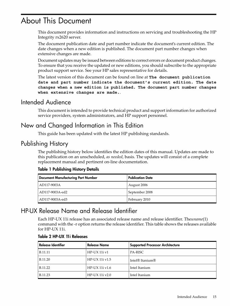
Publishing HistoryThe publishing history below identifies the edition dates of this manual. Updates are made tothis publication on an unscheduled, as needed, basis. The updates will consist of a completereplacement manual and pertinent on-line documentation.
Table 1 Publishing History Details
Publication DateDocument Manufacturing Part Number
August 2006AD117-9003A
September 2008AD117-9003A-ed2
February 2010AD117-9003A-ed3
HP-UX Release Name and Release IdentifierEach HP-UX 11i release has an associated release name and release identifier. Theuname(1)command with the -r option returns the release identifier. This table shows the releases availablefor HP-UX 11i.
Table 2 HP-UX 11i Releases
Supported Processor ArchitectureRelease NameRelease Identifier
PA-RISCHP-UX 11i v1B.11.11
Intel® Itanium®HP-UX 11i v1.5B.11.20
Intel ItaniumHP-UX 11i v1.6B.11.22
Intel ItaniumHP-UX 11i v2.0B.11.23
Intended Audience 15

Document OrganizationThis guide is divided into the following chapters.Chapter 1 Introduction Use this chapter to learn about the features and specifications of
the HP Integrity rx2620 server.Chapter 2 Controls, Ports, and LEDs Use this chapter to learn about the locations of the
external controls, ports, and LEDs on the server.Chapter 3 PoweringOff and PoweringOn the ServerUse this chapter to learn about powering
the server off and on.Chapter 4 Removing and Replacing Components Use this chapter to learn how to remove
and replace the field replaceable components (FRUs) on the server.Chapter 5 Troubleshooting Use this chapter to learn about troubleshooting problems you
may encounter with the server.Appendix A Parts Information Use this appendix to learn the location and part numbers of
the server components.Appendix B Operating System Boot and Shutdown Use this appendix to learn about booting
and shutting down the operating system on the server.Appendix C Utilities Use this appendix for information regarding the utilities available for
the server.Appendix D Console Setup and Connection Use this appendix to learn about the process for
setting up a console session and connecting to the server.
Typographic ConventionsThis document uses the following conventions.%, $, or # A percent sign represents the C shell system prompt. A dollar
sign represents the system prompt for the Bourne, Korn, andPOSIX shells. A number sign represents the superuser prompt.
Command A command name or qualified command phrase.Computer output Text displayed by the computer.Ctrl+x A key sequence. A sequence such as Ctrl+x indicates that you
must hold down the key labeled Ctrl while you press anotherkey or mouse button.
ENVIRONMENT VARIABLE The name of an environment variable, for example, PATH.[ERROR NAME] The name of an error, usually returned in the errno variable.Key The name of a keyboard key. Return and Enter both refer to the
same key.Term The defined use of an important word or phrase.User input Commands and other text that you type.Variable The name of a placeholder in a command, function, or other
syntax display that you replace with an actual value.[] The contents are optional in syntax. If the contents are a list
separated by |, you must choose one of the items.{} The contents are required in syntax. If the contents are a list
separated by |, you must choose one of the items.... The preceding element can be repeated an arbitrary number of
times.Indicates the continuation of a code example.
16
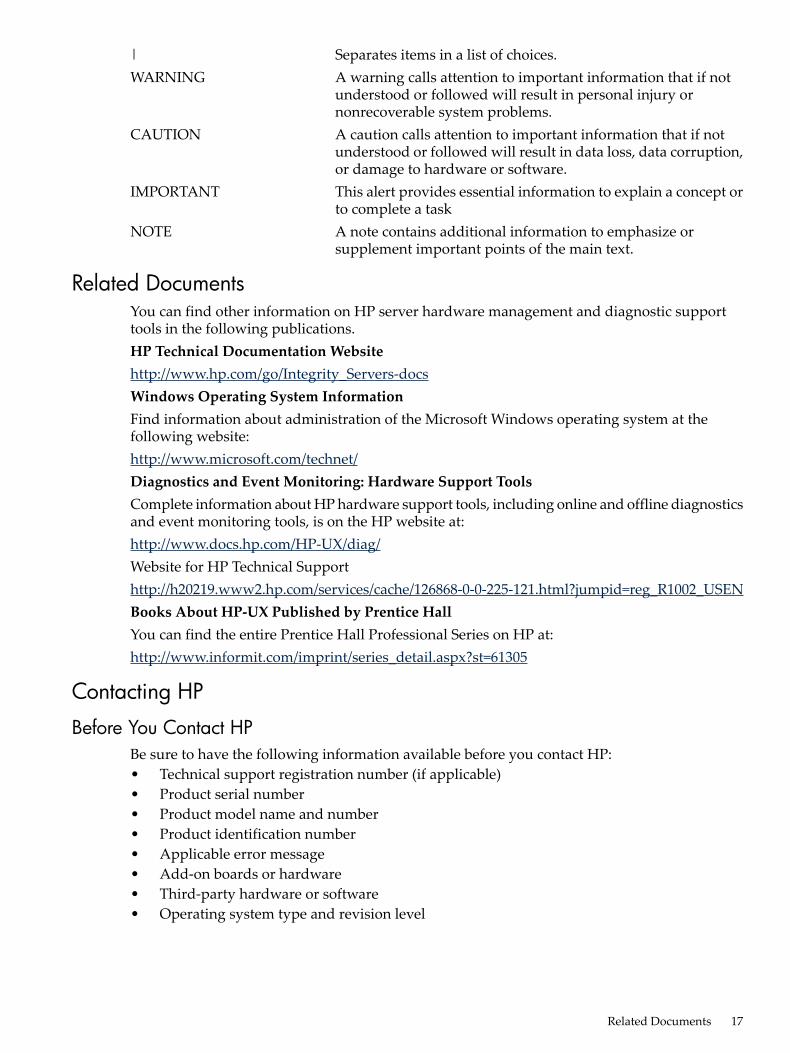
| Separates items in a list of choices.WARNING A warning calls attention to important information that if not
understood or followed will result in personal injury ornonrecoverable system problems.
CAUTION A caution calls attention to important information that if notunderstood or followed will result in data loss, data corruption,or damage to hardware or software.
IMPORTANT This alert provides essential information to explain a concept orto complete a task
NOTE A note contains additional information to emphasize orsupplement important points of the main text.
Related DocumentsYou can find other information on HP server hardware management and diagnostic supporttools in the following publications.HP Technical Documentation Websitehttp://www.hp.com/go/Integrity_Servers-docsWindows Operating System InformationFind information about administration of the Microsoft Windows operating system at thefollowing website:http://www.microsoft.com/technet/Diagnostics and Event Monitoring: Hardware Support ToolsComplete information about HP hardware support tools, including online and offline diagnosticsand event monitoring tools, is on the HP website at:http://www.docs.hp.com/HP-UX/diag/Website for HP Technical Supporthttp://h20219.www2.hp.com/services/cache/126868-0-0-225-121.html?jumpid=reg_R1002_USENBooks About HP-UX Published by Prentice HallYou can find the entire Prentice Hall Professional Series on HP at:http://www.informit.com/imprint/series_detail.aspx?st=61305
Contacting HP
Before You Contact HPBe sure to have the following information available before you contact HP:• Technical support registration number (if applicable)• Product serial number• Product model name and number• Product identification number• Applicable error message• Add-on boards or hardware• Third-party hardware or software• Operating system type and revision level
Related Documents 17

HP Contact InformationFor the name of the nearest HP authorized reseller:• In the United States, see the HP US service locator webpage (http://welcome.hp.com/country/
us/en/wwcontact.html.)• In other locations, see the Contact HP worldwide (in English) webpage:
http://welcome.hp.com/country/us/en/wwcontact.html.
For HP technical support:• In the United States, for contact options see the Contact HP United States webpage: (http://
welcome.hp.com/country/us/en/contact_us.html)To contact HP by phone:— Call 1-800-HP-INVENT (1-800-474-6836). This service is available 24 hours a day, 7 days
a week. For continuous quality improvement, calls may be recorded or monitored.— If you have purchased a Care Pack (service upgrade), call 1-800-633-3600. For more
information about Care Packs, see the HP website: (http://www.hp.com/hps).
• In other locations, see the Contact HP worldwide (in English) webpage (http://welcome.hp.com/country/us/en/wwcontact.html).
Subscription ServiceHP recommends that you register your product at the Subscriber's Choice for Business website:http://www.hp.com/country/us/en/contact_us.html.
Documentation FeedbackHP welcomes your feedback. To make comments and suggestions about product documentation,send a message to [email protected] the document title and manufacturing part number. All submissions become the propertyof HP.
18

1 IntroductionThe HP Integrity rx2620 server is a 2-socket server based on the Itanium® processor architecture.The server supports the following operating systems: Microsoft Windows®, HP-UX, Linux, andOpenVMS®. The server is available in either rack-mount or pedestal configurations. The serveraccommodates up to 12 DIMMs and internal peripherals including disks and a DVD. Its highavailability features include hot-swap fans, power supplies, and hot-plug disk drives.
Server OverviewThe HP Integrity rx2620 server chassis is a 2U Electronics Industry Association (EIA) enclosure,which mounts in any standard 19-inch EIA rack. All external cabling connects from the rear ofthe enclosure. With the server installed in the rack, service access is enhanced by the use of chassisslides. The server has bays to accommodate 1 + 1 redundant, hot-swappable power supplies,accessible from the front of the product. There are three low-profile hot swappable hard drivesaccessible from the front, and a slim-line optical drive for a CD-R, CD-RW, DVD-R, or DVD+RW.There are N + 1 redundant, hot-swappable server fans, all clearly identified and easily accessible.Server status indication, a power switch, server locator switch, and LED are located in the frontwithin the bezel. A server locator switch and LED is in the back of the server for easy identificationin the rack. See Figure 1-1, Figure 1-2, and Figure 1-3 for front and back views of the server.
Figure 1-1 HP Integrity rx2620 Server (front view)
Figure 1-2 HP Integrity rx2620 Server (front view with bezel removed)
Figure 1-3 HP Integrity rx2620 Server (rear view)
Server DimensionsTable 1-1 shows the dimensions and weight of the server.
Server Overview 19
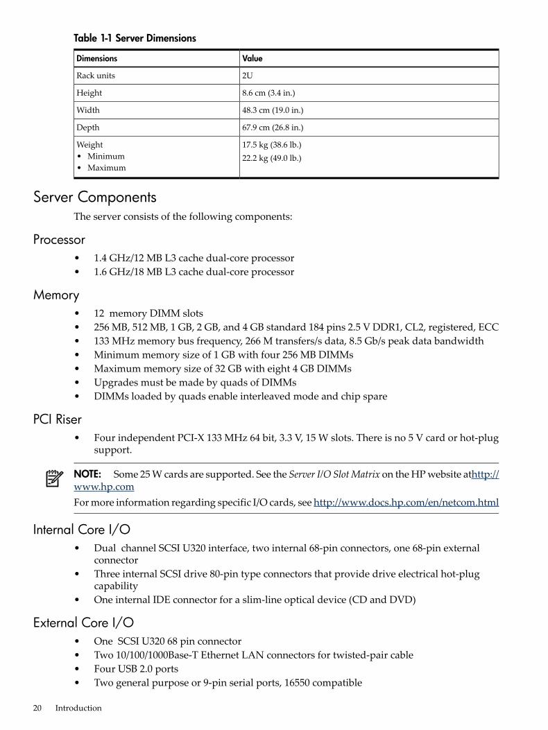
Table 1-1 Server Dimensions
ValueDimensions
2URack units
8.6 cm (3.4 in.)Height
48.3 cm (19.0 in.)Width
67.9 cm (26.8 in.)Depth
17.5 kg (38.6 lb.)22.2 kg (49.0 lb.)
Weight• Minimum• Maximum
Server ComponentsThe server consists of the following components:
Processor• 1.4 GHz/12 MB L3 cache dual-core processor• 1.6 GHz/18 MB L3 cache dual-core processor
Memory• 12 memory DIMM slots• 256 MB, 512 MB, 1 GB, 2 GB, and 4 GB standard 184 pins 2.5 V DDR1, CL2, registered, ECC• 133 MHz memory bus frequency, 266 M transfers/s data, 8.5 Gb/s peak data bandwidth• Minimum memory size of 1 GB with four 256 MB DIMMs• Maximum memory size of 32 GB with eight 4 GB DIMMs• Upgrades must be made by quads of DIMMs• DIMMs loaded by quads enable interleaved mode and chip spare
PCI Riser• Four independent PCI-X 133 MHz 64 bit, 3.3 V, 15 W slots. There is no 5 V card or hot-plug
support.
NOTE: Some 25 W cards are supported. See the Server I/O SlotMatrix on the HP website athttp://www.hp.comFor more information regarding specific I/O cards, see http://www.docs.hp.com/en/netcom.html
Internal Core I/O• Dual channel SCSI U320 interface, two internal 68-pin connectors, one 68-pin external
connector• Three internal SCSI drive 80-pin type connectors that provide drive electrical hot-plug
capability• One internal IDE connector for a slim-line optical device (CD and DVD)
External Core I/O• One SCSI U320 68 pin connector• Two 10/100/1000Base-T Ethernet LAN connectors for twisted-pair cable• Four USB 2.0 ports• Two general purpose or 9-pin serial ports, 16550 compatible
20 Introduction
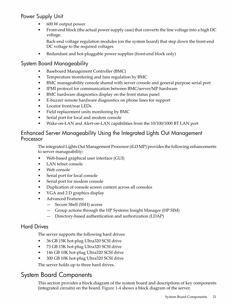
Power Supply Unit• 600 W output power• Front-end block (the actual power supply case) that converts the line voltage into a high DC
voltage.Back-end voltage regulation modules (on the system board) that step down the front-endDC voltage to the required voltages
• Redundant and hot-pluggable power supplies (front-end block only)
System Board Manageability• Baseboard Management Controller (BMC)• Temperature monitoring and fans regulation by BMC• BMC manageability console shared with server console and general purpose serial port• IPMI protocol for communication between BMC/server/MP hardware• BMC hardware diagnostics display on the front status panel• E-buzzer remote hardware diagnostics on phone lines for support• Locator front/rear LEDs• Field replacement units monitoring by BMC• Serial port for local and modem console• Wake-on-LAN and Alert-on-LAN capabilities from the 10/100/1000 BT LAN port
Enhanced Server Manageability Using the Integrated Lights Out ManagementProcessor
The integrated Lights Out Management Processor (iLO MP) provides the following enhancementsto server manageability:• Web-based graphical user interface (GUI)• LAN telnet console• Web console• Serial port for local console• Serial port for modem console• Duplication of console screen content across all consoles• VGA and 2 D graphics display• Advanced Features:
— Secure Shell (SSH) access— Group actions through the HP Systems Insight Manager (HP SIM)— Directory-based authentication and authorization (LDAP)
Hard DrivesThe server supports the following hard drives:• 36 GB 15K hot-plug Ultra320 SCSI drive• 73 GB 15K hot-plug Ultra320 SCSI drive• 146 GB 10K hot-plug Ultra320 SCSI drive• 300 GB 10K hot-plug Ultra320 SCSI driveThe server holds up to three hard drives.
System Board ComponentsThis section provides a block diagram of the system board and descriptions of key components(integrated circuits) on the board. Figure 1-4 shows a block diagram of the server.
System Board Components 21
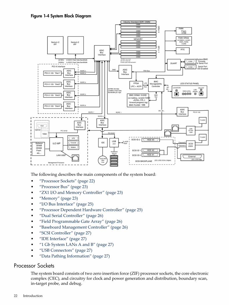
Figure 1-4 System Block Diagram
The following describes the main components of the system board:• “Processor Sockets” (page 22)• “Processor Bus” (page 23)• “ZX1 I/O and Memory Controller” (page 23)• “Memory” (page 23)• “I/O Bus Interface” (page 25)• “Processor Dependent Hardware Controller” (page 25)• “Dual Serial Controller” (page 26)• “Field Programmable Gate Array” (page 26)• “Baseboard Management Controller” (page 26)• “SCSI Controller” (page 27)• “IDE Interface” (page 27)• “1 Gb System LANs A and B” (page 27)• “USB Connectors” (page 27)• “Data Pathing Information” (page 27)
Processor SocketsThe system board consists of two zero insertion force (ZIF) processor sockets, the core electroniccomplex (CEC), and circuitry for clock and power generation and distribution, boundary scan,in-target probe, and debug.
22 Introduction

The front side bus (FSB) is the IA64 processor bus, based on bus protocol from Intel. Unlikeprevious PA-RISC microprocessors that utilized HP proprietary processor buses, this processoris designed to utilize the FSB. This allows processor field replaceable units (FRUs) to be droppedin, provided that electrical and mechanical compatibility and support circuitry exist. For thepurposes of this document, a FRU consists of a single processor with power pod, and the heatsink assembly.Each processor plugs directly into, and is powered by its own 12 V to 1.2 V power pod. Otherpower for the system board comes from multiple on-board DC to DC converters. Each processoris attached to the board through a ZIF socket and the entire FRU secured by a heat sink.
Processor BusThe FSB in this product runs at 200 MHz. Data on the FSB are transferred at a double data rate,which allows a peak FSB bandwidth of 6.4 Gb/s.
ZX1 I/O and Memory ControllerThe server supports the following features of the ZX1 I/O and memory controller chip:• 8.5 Gb/s peak I/O bandwidth• Seven communication paths• Peak memory bandwidth of 8.5 Gb/s• Two memory cells, 144 data bits each
MemoryThe memory subsystem provides two memory cells. Each cell is 144 data bits wide. Each cell hassix DIMM slots, which means a total of 12 DIMM slots are available. The memory bus clock speedis 133 MHz, and the data transfer rate is 266 Mtransfers/s as data is clocked on both edges of theclock. The peak data bandwidth for this memory subsystem design is 8.5 Gb/s. Load DIMMs inquads with qualified modules. Memory is protected by data ECC, and the hardwareimplementation supports chip-spare.The minimum amount of memory supported by the server is 1 GB (four 256 MB modules). Themaximum amount of memory supported by the server is 32 GB (eight 4 GB modules).This design does not support any nonindustry-standard DDR DIMMs. Only qualified DIMMsare supported. Figure 1-5 shows a block diagram of the server memory.
System Board Components 23

Figure 1-5 Memory Block Diagram
Memory ArchitectureThe I/O ASIC memory interface supports two DDR cells. Each cell is 144 data bits wide. Thememory subsystem physical design uses a comb-filter termination scheme for the data and theaddress and control buses. This topology is similar to other DDR designs. Clocks are distributeddirectly from the I/O ASIC. Each clock pair drives two DIMMs.Memory data is protected by the ECC. Eight ECC bits per DIMM protect 64 bits of data. The useof ECC allows correction of single-bit errors, and detection of multi-bit errors. Only DIMMs withECC are qualified or supported.
DIMMs
The memory subsystem supports only DDR SDRAM (Double Data Rate Synchronous DynamicRandom Access Memory) technology utilizing industry-standard PC-1600 type DDR SDRAMDIMMs, 1.2" tall. The DIMMs use a 184-pin JEDEC standard connector.DIMMs are loaded in a group of four, known as a quad. All four DIMMs in a quad must be thesame size. Table 1-2 summarizes the memory solutions.
Table 1-2 Memory Array Capacities
DDR SDRAM Count, Type, and TechnologySingle DIMM SizeMininum/Maximum Memory Size
18 x 32 MB x 4 DDR1 SDRAMs (128 MB)256 MB DIMM1 GB / 3 GB
36 x 32 MB x 4 DDR1 SDRAMs (128 MB)512 MB DIMM2 GB / 6 GB
36 x 64 MB x 4 DDR1 SDRAMs (256 MB)1024 MB DIMM4 GB / 12 GB
24 Introduction
Table 1-2 Memory Array Capacities (continued)
DDR SDRAM Count, Type, and TechnologySingle DIMM SizeMininum/Maximum Memory Size
36 x 128 MB x 4 DDR1 SDRAMs (512 MB)2048 MB DIMM8 GB / 24 GB
36 x 256 MB x 4 DDR1 SDRAMs (1024 MB)4096 MB DIMM32 GB / 32 GB
Chip Spare Functionality
Chip spare enables an entire DDR SDRAM chip on a DIMM to be bypassed in the event that amulti-bit error is detected on the DDR SDRAM. To use the chip spare functionality on yourserver, use only DIMMs built with ×4 DDR SDRAM parts, and load these DIMMs in quads.The memory subsystem design supports the I/O ASIC chip spare functionality. Chip spare enablesan entire SDRAM chip on a DIMM to be bypassed/replaced in the event that a multi-bit error isdetected on that SDRAM. To use the chip spare functionality, use only DIMMs built with x4SDRAM parts, and load these DIMMs in quads (two DIMMs per memory cell, loaded in thesame location in each memory cell). Each DIMM within a quad must be identical to all the otherDIMMs in the quad.Chip spare is achieved if four identical DIMMs are loaded into a quad. If more DIMMs are added,they must be loaded in quads to maintain the chip spare functionality. So, if more DIMMs areadded in to the example case, four identical DIMMs (identical to each other, but can be differentfrom the original quad that was loaded) must be loaded into the next quad. However, if you areusing 4 GB DIMMS, the only configuration supported is eight 4 GB DIMMS in the first threequads, with no other DIMMs in the remaining quad. For slot and quad locations, see Figure 4-23(page 58).
Serial Presence Detect
Each DIMM contains an I2C electronically erasable programmable read-only memory (EEPROM)whose content describes the module characteristics. This feature is called serial presence detect(SPD). Firmware typically uses this information to detect unmatched pairs of DIMMs andconfigure certain memory subsystem parameters. The SPD information for DIMMs loaded inthe server is also accessible to the BMC through the I2C bus.
I/O Bus InterfaceThe I/O bus interface provides these features:• Industry-standard PCI 33 MHz and 66 MHz, PCI-X 66 MHz to 133 MHz, 32 or 64 data bit
support• 3.3 V PCI only (does not support 5 V PCI)• DMA performance optimization• 3.3 V or Universal keyed PCI card support (not 5 V keyed PCI cards)• Up to four PCI sockets
Processor Dependent Hardware ControllerThe PDH controller provides these features:• 16-bit PDH bus with reserved address space for the following:• Flash memory—
— Nonvolatile memory— Scratch RAM— Real-time Clock— UARTs— External registers— Firmware read/writable registers
System Board Components 25
— Two general purpose 32-bit registers— Semaphore registers— Monarch selection registers— Test and Reset register
• Reset and INIT generation
Dual Serial ControllerThe dual serial controller is a dual universal asynchronous receiver and transmitter (DUART).This chip provides enhanced UART functions with 16-byte first-in, first-out (FIFO), a modemcontrol interface. Registers on this chip provide onboard error indications and operation status.An internal loopback capability provides onboard diagnostics.Features include:• Data rates up to 115.2 kbps• 16550A fully compatible controller• A 16-byte transmit FIFO that reduces the bandwidth requirement of the external CPU• A 16-byte receive FIFO with four selectable interrupt trigger levels and error flags that reduce
the bandwidth requirement of the external CPU• UART control that provides independent transmit and receive• Modem control signals (-CTS, -RTS, -DSR, -DTR, -RI, -CD, and software controllable line
break)• Programmable character lengths (5, 6, 7, 8) with Even, Odd or No Parity• A status report register
Field Programmable Gate ArrayThe field programmable gate array (FPGA) provides ACPI and LPC support for the PDH busand provides these features:• ACPI 2.0 interface• LPC bus interface to support BMC• Decoding logic for PDH devices
Baseboard Management ControllerThe baseboard management controller (BMC) supports the industry-standard Intelligent PlatformManagement Interface (IPMI) specification. This specification describes the management featuresthat have been built into the system board. These features include: local and remote diagnostics,console support, configuration management, hardware management, and troubleshooting.The baseboard management controller provides the following:• Compliance with IPMI 1.0• Tachometer inputs for fan speed monitoring• Pulse width modulator outputs for fan speed control• Push-button inputs for front panel buttons and switches• One serial port, multiplexed with the server console port• Remote access and intelligent chassis management bus (ICMB) support• Three I2C primary/secondary ports (one port is used for IPMB)• Low pin count (LPC) bus provides access to three keyboard controller style (KCS) and
one-block transfer (BT) interface• 32-bit ARM7 processor
26 Introduction

• 160-pin low profile flat pack (LQFP) package• Firmware is provided for the following interfaces:
— Intelligent platform management interface (IPMI)— Intelligent platform management bus (IPMB)
SCSI ControllerThe SCSI controller is an LSI Logic 53C1030 chip. This chip is fully compliant with the SCSIPeripheral Interface-3 Specification (SPI-3). It has two independent SCSI channels supportingdevices at speeds up to 320 Mb/s each. The 53C1030 adheres to the PCI-X addendum to the PCILocal Specification and is hard-wired to PCI ID 1, which corresponds to bit 17 of the PCI ADbus.
IDE InterfaceThe IDE controller (PCI649) supports the ATAPI zero to five modes (from 16 to 100 Mb/s). Theusable speed on this server is limited to 16 MHz (ATA-33 mode, 33 Mb/s) because the slimlineCD/DVD devices do not support the ATA-66 and 100 modes.The primary IDE channel is the only channel that is implemented. The IDE cable provides onlyone drive connector, of the primary type, for the DVD peripheral.
1 Gb System LANs A and BThe 1 Gb system LAN ports A and B provide:• Main server LANs• 10/100/1000 Mb capability
USB ConnectorsThe USB connectors provide:• High speed 480 Mb/s capability• Full speed 12 Mb/s• Low speed 1.5 Mb/s• USB keyboard and mouse support• HP-UX support for HP USB keyboard and mouse
Data Pathing InformationTable 1-3 shows data path information for the server.
Table 1-3 Data Pathing
PathDevice IDFunctionNumber
DeviceNumber
Bus NumberSlot ID
Acpi(HWP0002,PNP0A03,400)/Pci(1|0)0x000B00018001
Acpi(HWP0002,PNP0A03,300)/Pci(1|0)0x102900016002
Acpi(HWP0002,PNP0A03,200)/Pci(1|0)0x01A700014003
Acpi(HWP0002,PNP0A03,600)/Pci(1|0)0x23120001C004
System Board Components 27

28
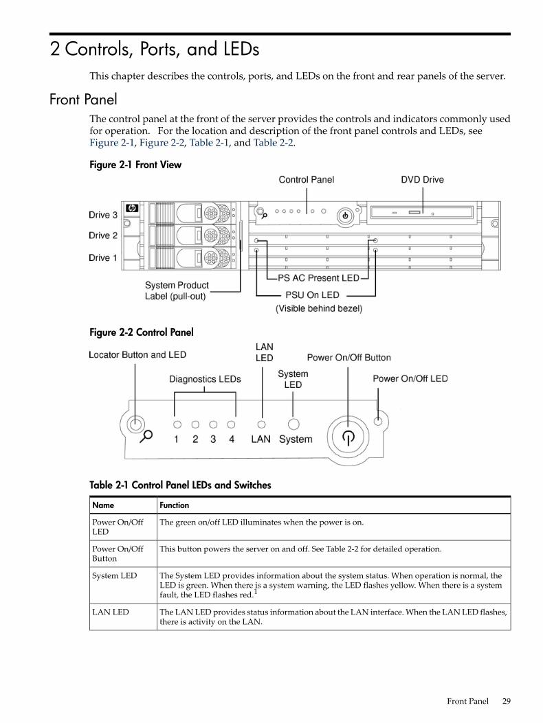
2 Controls, Ports, and LEDsThis chapter describes the controls, ports, and LEDs on the front and rear panels of the server.
Front PanelThe control panel at the front of the server provides the controls and indicators commonly usedfor operation. For the location and description of the front panel controls and LEDs, seeFigure 2-1, Figure 2-2, Table 2-1, and Table 2-2.
Figure 2-1 Front View
Figure 2-2 Control Panel
Table 2-1 Control Panel LEDs and Switches
FunctionName
The green on/off LED illuminates when the power is on.Power On/OffLED
This button powers the server on and off. See Table 2-2 for detailed operation.Power On/OffButton
The System LED provides information about the system status. When operation is normal, theLED is green. When there is a system warning, the LED flashes yellow. When there is a systemfault, the LED flashes red.1
System LED
The LAN LED provides status information about the LAN interface. When the LAN LED flashes,there is activity on the LAN.
LAN LED
Front Panel 29

Table 2-1 Control Panel LEDs and Switches (continued)
FunctionName
The four diagnostic LEDs operate in conjunction with the system LED to provide diagnosticinformation about the system.1
Diagnostic LEDs1 – 4
The Locator button and LED are used to help locate this server within a rack of servers. Whenthe button is engaged, the blue LED illuminates and an additional blue LED on the rear panel ofthe server illuminates. This function can be remotely activated.
Locator Buttonand LED
1 See Chapter 5: “Troubleshooting” (page 95) for information provided by the system and diagnostic LEDs.
Table 2-2 Power On/Off Button
DescriptionButton/Switch
Controls the power supply (turns system power on or off) if power is available to the powersupply. (Controls both power supplies if two are installed).If power is off but power is available to the power supplies, pressing the Power button:• Momentarily (less than 5 seconds) turns on the power supplies and applies power to
server circuits.• More than 5 seconds, then released, has no effect.If power is on and the system is at initial system loader, pressing the Power button:• Momentarily (less than one second) has no effect.• More than one second, but less than five seconds—do not use. This initiates e-buzzer
functions that are not supported in the server.• More than five seconds, then released, causes an immediate hard power off.If power is on and the system is at BCH, pressing the Power button:• Momentarily (less than one second) causes a immediate and hard power off.• More than one second, but less than five seconds—do not use. This initiates e-buzzer
functions that are not supported in the server.• More than five seconds, then released, causes an immediate hard power off.If power is on but the operating system shuts down, pressing the Power button:• Momentarily (less than 5 seconds) causes a system power off.• More than five seconds, then held, causes a system power off.If the OS is running, pressing the Power button:• Momentarily (less than 5 seconds) requests a soft power down by the operating system.
The operating system determines if the power off request is to be honored.• More than five seconds, then released, causes an immediate hard power off without
allowing the operating system to close open files or flush disk caches possibly resultingin a corrupted disk system or file. This should only be used when the operating systemis not responding to user requests.
Power Button
Hot-Plug Disk Drive IndicatorsThe hot-plug disk drives have two LEDs per drive. For the location and description of the harddrive LEDs, see Figure 2-3 and Table 2-3.
Figure 2-3 Hot-Plug Disk Drive LED Indicators
30 Controls, Ports, and LEDs
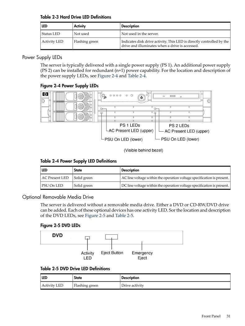
Table 2-3 Hard Drive LED Definitions
DescriptionActivityLED
Not used in the server.Not usedStatus LED
Indicates disk drive activity. This LED is directly controlled by thedrive and illuminates when a drive is accessed.
Flashing greenActivity LED
Power Supply LEDsThe server is typically delivered with a single power supply (PS 1). An additional power supply(PS 2) can be installed for redundant (n+1) power capability. For the location and description ofthe power supply LEDs, see Figure 2-4 and Table 2-4.
Figure 2-4 Power Supply LEDs
Table 2-4 Power Supply LED Definitions
DescriptionStateLED
AC line voltage within the operation voltage specification is present.Solid greenAC Present LED
DC line voltage within the operation voltage specification is present.Solid greenPSU On LED
Optional Removable Media DriveThe server is delivered without a removable media drive. Either a DVD or CD-RW/DVD drivecan be added. Each of these optional devices has one activity LED. Sor the location and descriptionof the DVD LEDs, see Figure 2-5 and Table 2-5.
Figure 2-5 DVD LEDs
Table 2-5 DVD Drive LED Definitions
DescriptionStateLED
Drive activityFlashing greenActivity LED
Front Panel 31

Rear PanelThe server rear panel includes communication ports, I/O ports, AC power connectors, and theLocator LED/button. Additional LEDs located on the rear panel of the server signal the operationalstatus of the LAN connector of the optional iLO MP. For the location and description of the portsand connectors, see Figure 2-6 and Table 2-6.
Figure 2-6 Rear View
Table 2-6 Rear Panel Connectors and Switches
FunctionConnector/Switch
Primary power connection (AC1) for the server. A second connector (AC2) is available forthe optional, N+1 redundant power supply.
AC Power
68-pin, low-voltage differential, single-ended U320 SCSI. This connector provides externalSCSI connection on Core SCSI Channel B
LVD/SE SCSI
10/100/1000 base-T Ethernet LAN connector(LAN Gb A) 10/100/1000LAN
10/100/1000 base-T Ethernet LAN connector(LAN Gb B) 10/100/1000LAN
9-pin male serial connectors. Serial Port A is used as the console connection when theoptional iLO MP is not installed.
Serial A (console) andSerial B
Four universal serial bus (USB 2.0) connectorsUSB
Transfer of Control button. Halts all system processing and I/O activity and restarts thecomputer system preserving system memory contents.
TOC
The Locator button and LED are used to help locate a server within a rack of servers. Whenthe button is engaged, the blue LED illuminates and an additional blue LED on the frontpanel of the server illuminates. This function can be remotely activated by the LOCcommand of the optional iLO MP.
Locator Button and LED
15-pin female video connector. The optional iLO MP provides a connector to support aVGA monitor.
VGA (optional)1
32 Controls, Ports, and LEDs
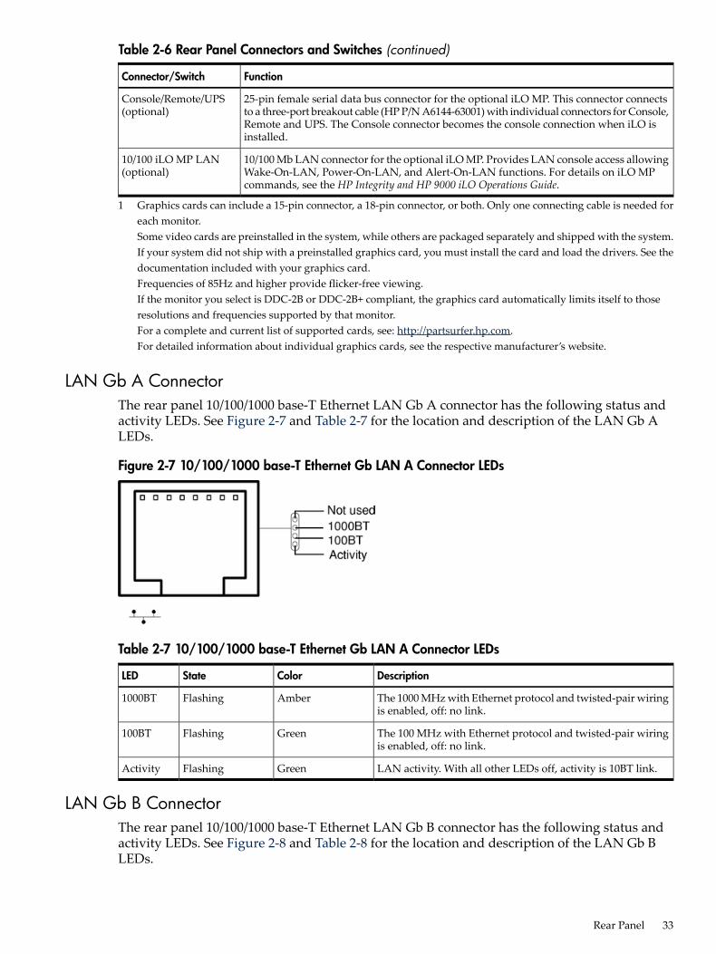
Table 2-6 Rear Panel Connectors and Switches (continued)
FunctionConnector/Switch
25-pin female serial data bus connector for the optional iLO MP. This connector connectsto a three-port breakout cable (HP P/N A6144-63001) with individual connectors for Console,Remote and UPS. The Console connector becomes the console connection when iLO isinstalled.
Console/Remote/UPS(optional)
10/100 Mb LAN connector for the optional iLO MP. Provides LAN console access allowingWake-On-LAN, Power-On-LAN, and Alert-On-LAN functions. For details on iLO MPcommands, see the HP Integrity and HP 9000 iLO Operations Guide.
10/100 iLO MP LAN(optional)
1 Graphics cards can include a 15-pin connector, a 18-pin connector, or both. Only one connecting cable is needed foreach monitor.Some video cards are preinstalled in the system, while others are packaged separately and shipped with the system.If your system did not ship with a preinstalled graphics card, you must install the card and load the drivers. See thedocumentation included with your graphics card.Frequencies of 85Hz and higher provide flicker-free viewing.If the monitor you select is DDC-2B or DDC-2B+ compliant, the graphics card automatically limits itself to thoseresolutions and frequencies supported by that monitor.For a complete and current list of supported cards, see: http://partsurfer.hp.com.For detailed information about individual graphics cards, see the respective manufacturer’s website.
LAN Gb A ConnectorThe rear panel 10/100/1000 base-T Ethernet LAN Gb A connector has the following status andactivity LEDs. See Figure 2-7 and Table 2-7 for the location and description of the LAN Gb ALEDs.
Figure 2-7 10/100/1000 base-T Ethernet Gb LAN A Connector LEDs
Table 2-7 10/100/1000 base-T Ethernet Gb LAN A Connector LEDs
DescriptionColorStateLED
The 1000 MHz with Ethernet protocol and twisted-pair wiringis enabled, off: no link.
AmberFlashing1000BT
The 100 MHz with Ethernet protocol and twisted-pair wiringis enabled, off: no link.
GreenFlashing100BT
LAN activity. With all other LEDs off, activity is 10BT link.GreenFlashingActivity
LAN Gb B ConnectorThe rear panel 10/100/1000 base-T Ethernet LAN Gb B connector has the following status andactivity LEDs. See Figure 2-8 and Table 2-8 for the location and description of the LAN Gb BLEDs.
Rear Panel 33

Figure 2-8 10/100/1000 base-T Ethernet Gb LAN B Connector LEDs
Table 2-8 10/100/1000 base-T Ethernet Gb LAN B Connector LEDs
DescriptionColorLocation
1000 MHz with Ethernet protocol and twisted-pair wiring is enabledAmberSpeed (upper left)
100 MHz with Ethernet protocol and twisted-pair wiring is enabledGreen
No link10 MHz with Ethernet protocol and twisted-pair wiring is enabled
Off
LAN activityFlashing greenLink (upper right)
No linkOff
Management Processor LAN LEDsThe LAN port of the optional Integrated Lights Out (iLO) Management Processor (MP) uses anRJ-45 type connector. This connector has four LEDs that signal status and activity. The iLO MPis required for Proactive 24 or Critical Service support. See Figure 2-9 and Table 2-9 for the locationand description of the MP LAN LEDs.
Figure 2-9 MP LAN LEDs
Table 2-9 iLO MP LAN LEDs
DescriptionColorLED
iLO is running self-test or error detectedYellowSelf-test
10 BT link establishedGreen10 BT
10 BT link activityFlashing green
Off: no link
100 BT link establishedGreen100 BT
100 BT link activityFlashing green100 BT
Off: no link100 BT
34 Controls, Ports, and LEDs
Table 2-9 iLO MP LAN LEDs (continued)
DescriptionColorLED
Standby power onGreenStandbyPower
Off: standby power offStandbyPower
Rear Panel 35

36
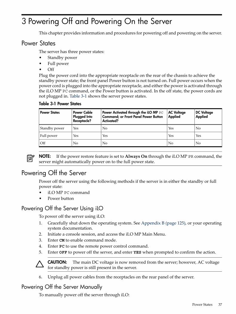
3 Powering Off and Powering On the ServerThis chapter provides information and procedures for powering off and powering on the server.
Power StatesThe server has three power states:• Standby power• Full power• OffPlug the power cord into the appropriate receptacle on the rear of the chassis to achieve thestandby power state; the front panel Power button is not turned on. Full power occurs when thepower cord is plugged into the appropriate receptacle, and either the power is activated throughthe iLO MP PC command, or the Power button is activated. In the off state, the power cords arenot plugged in. Table 3-1 shows the server power states.
Table 3-1 Power States
DC VoltageApplied
AC VoltageApplied
Power Activated through the iLO MP PCCommand; or Front Panel Power ButtonActivated?
Power CablePlugged IntoReceptacle?
Power States
NoYesNoYesStandby power
YesYesYesYesFull power
NoNoNoNoOff
NOTE: If the power restore feature is set to Always On through the iLO MP PR command, theserver might automatically power on to the full power state.
Powering Off the ServerPower off the server using the following methods if the server is in either the standby or fullpower state:• iLO MP PC command• Power button
Powering Off the Server Using iLOTo power off the server using iLO:1. Gracefully shut down the operating system. See Appendix B (page 125), or your operating
system documentation.2. Initiate a console session, and access the iLO MP Main Menu.3. Enter CM to enable command mode.4. Enter PC to use the remote power control command.5. Enter OFF to power off the server, and enter YES when prompted to confirm the action.
CAUTION: The main DC voltage is now removed from the server; however, AC voltagefor standby power is still present in the server.
6. Unplug all power cables from the receptacles on the rear panel of the server.
Powering Off the Server ManuallyTo manually power off the server through iLO:
Power States 37

1. Gracefully shut down the operating system. See Appendix B (page 125), or your operatingsystem documentation.
2. Press the Power button to power off the server.
IMPORTANT: The main DC voltage is now removed from the server; however, AC voltagefor standby power is still present in the server.
3. Unplug all power cables from the receptacles on the rear panel of the server.
Powering On the ServerPower on the server to full power using the following methods if the server is in the standbypower state:• iLO MP PC command• Power button
Powering On the Server Using iLO
NOTE: If the power restore feature is set to Always On through the iLO MP PR command, theserver might automatically power on to the full power state.
To power on the server through iLO:1. Plug all power cables into the receptacles on the rear panel of the server.2. Initiate a console session, and access the iLO MP Main Menu.3. Enter CM to enable command mode.4. Enter PC to use the remote power control command.5. Enter ON to power on the server, and enter YES when prompted to confirm the action.6. Start the operating system. See Appendix B (page 125), or your operating system
documentation.
Powering On the Server Manually
NOTE: If the power restore feature is set to Always On through the iLO MP PR command, theserver might automatically power on to the full power state.
To manually power on the server:1. Plug all power cables into the receptacles on the rear panel of the server.2. Press the Power button to start the server.3. Start the operating system. See Appendix B (page 125), or your operating system
documentation.
38 Powering Off and Powering On the Server
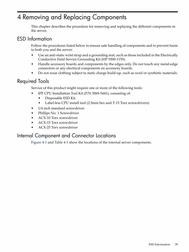
4 Removing and Replacing ComponentsThis chapter describes the procedure for removing and replacing the different components inthe server.
ESD InformationFollow the procedures listed below to ensure safe handling of components and to prevent harmto both you and the server:• Use an anti-static wrist strap and a grounding mat, such as those included in the Electrically
Conductive Field Service Grounding Kit (HP 9300-1155).• Handle accessory boards and components by the edges only. Do not touch any metal-edge
connectors or any electrical components on accessory boards.• Do not wear clothing subject to static charge build-up, such as wool or synthetic materials.
Required ToolsService of this product might require one or more of the following tools:• IPF CPU Installation Tool Kit (P/N 5069-5441), consisting of:
• Disposable ESD Kit• Label-less CPU install tool (2.5mm hex and T-15 Torx screwdrivers)
• 1/4 inch standard screwdriver• Phillips No. 1 Screwdriver• ACX-10 Torx screwdriver• ACX-15 Torx screwdriver• ACX-25 Torx screwdriver
Internal Component and Connector LocationsFigure 4-1 and Table 4-1 show the locations of the internal server components.
ESD Information 39
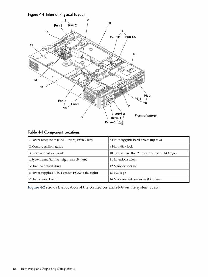
Figure 4-1 Internal Physical Layout
Table 4-1 Component Locations
8 Hot-pluggable hard drives (up to 3)1 Power receptacles (PWR 1 right, PWR 2 left)
9 Hard disk lock2 Memory airflow guide
10 System fans (fan 2 - memory, fan 3 - I/O cage)3 Processor airflow guide
11 Intrusion switch4 System fans (fan 1A - right, fan 1B - left)
12 Memory sockets5 Slimline optical drive
13 PCI cage6 Power supplies (PSU1 center; PSU2 to the right)
14 Management controller (Optional)7 Status panel board
Figure 4-2 shows the location of the connectors and slots on the system board.
40 Removing and Replacing Components

Figure 4-2 System Board Connectors and Slots
Table 4-2 Connector Locations
17 PCI backplane connector9 PDH connectors1 External SCSI connector
18 Optical drive connector10 Power module power connector2 SCSI connectors A and B
19 iLO hardware connector11 ZX1 memory and I/O controller (underheat sink)
3 CPU 0 slot
20 HP ZX1 I/O adapter12 Memory sockets (4)4 CPU 1 slot
21 Serial ports (2)13 Status panel connector5 Turbo fan power connectors (2)
22 USB connectors (4)14 Power module auxiliary connector6 Fan Connector
23 LAN connectors (2)15 SCSI backplane power connector7 VRM cards (5)
16 PCI/memory fan cable connector8 Battery
Internal Component and Connector Locations 41

Removing and Replacing System Top Metal Cover and BezelsTo upgrade, remove, or replace most server components, you must first remove the top metalcover from the server chassis.
WARNING! Do not remove the server covers without powering off the server and unpluggingthe power cord from the outlet or power protection device unless you are only replacing ahot-swappable fan.When the server is running, you must replace the top metal cover within 30 minutes to preventcomponents from overheating. If the top metal cover is not replaced within 30 minutes, the serverautomatically shuts down. If the server shuts off, always replace the cover before turning theserver back on.
Rack-Mount SystemThis section explains how to remove and replace the cover for the rack-mount configuration.To access the internal components on a rack-mounted server, pull the server out on the rail guidesand remove the top metal cover.
Accessing a Rack Mounted ServerThe server is designed to be rack mounted. The following procedure explains how to gain accessto a server that is mounted in an approved rack. For rack installation instructions, review theHP Integrity rx2620 Server Rack Installation Guide.
WARNING! Ensure that all anti-tip features (front and rear anti-tip feet installed; adequateballast properly placed, and so on) are employed before you extend the server.
Extending the Server from the Rack
NOTE: Ensure that there is enough area (approximately 1.5 meters (4.5 ft.)) to fully extend theserver and work on it.
To extend the server from the rack:1. Power off the server and disconnect the power cable and all other cables from the back of
the server. See “Powering Off the Server” (page 37).2. Release the rack latches by rotating them outward. See Figure 4-3.
42 Removing and Replacing Components

Figure 4-3 Release the Rack Latches
3. Slide the server out of the rack until the guide-rail release clips are visible.
Inserting the Server into the Rack
To insert the server into the rack, perform the following step:1. Press the rail clips on either side of the server inward and push the server into the rack until
it stops.2. Verify that the rack latches are closed.
Removing and Replacing the Top Metal CoverThe following procedures describe how to remove and replace the top metal cover.
Removing the Top Metal Cover1. Power off the server and disconnect the power cable and all other cables from the back of
the server.
CAUTION: When the server is running, you must replace the top metal cover within 30minutes to prevent components from overheating. If the top metal cover is not replacedwithin 30 minutes, the server automatically shuts down.If the server shuts down, replace the top metal cover before you restart the server.
2. Ensure the top metal cover lock keyswitch is in the unlocked position. Rotate the blue releaselever toward the back of the server and slide the cover toward the back of the server. SeeFigure 4-4.
Removing and Replacing System Top Metal Cover and Bezels 43
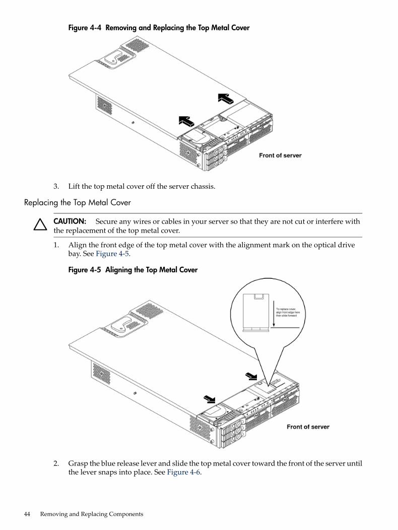
Figure 4-4 Removing and Replacing the Top Metal Cover
3. Lift the top metal cover off the server chassis.
Replacing the Top Metal Cover
CAUTION: Secure any wires or cables in your server so that they are not cut or interfere withthe replacement of the top metal cover.
1. Align the front edge of the top metal cover with the alignment mark on the optical drivebay. See Figure 4-5.
Figure 4-5 Aligning the Top Metal Cover
2. Grasp the blue release lever and slide the top metal cover toward the front of the server untilthe lever snaps into place. See Figure 4-6.
44 Removing and Replacing Components

Figure 4-6 Closing the Top Metal Cover
3. Slide the server into the rack enclosure and connect the power cables.
Removing and Replacing the Front BezelYou must remove the front bezel from the chassis to remove or replace the power supplies orthe optical drive.
Removing the Front Bezel1. Press in the retaining clips located on the right-side of the front panel. See Figure 4-7.
Figure 4-7 Front Bezel Retaining Clip
2. Rotate the front panel out and lift if away from the server chassis.
Replacing the Front Bezel1. Insert the bezel latches into the matching slots on the server chassis. See Figure 4-8 .
Removing and Replacing System Top Metal Cover and Bezels 45
2. Swing the bezel and push toward the front of the server until the bezel locks into place.
Figure 4-8 Replacing the Front Bezel
Removing and Replacing Hot-Swap and Hot-Plug DevicesThe server has hard drives that are hot-pluggable and power supplies and fans that arehot-swappable. This section explains how to replace the following devices while the server isrunning:• System fans• Power supplies• Hard drivesThere is a significant difference between the terms hot-swap and hot-plug:• Hot swapping happens at the device level. A hot-swappable device manages insertion or
removal on its own without assistance from operating system commands.• Hot-plugging allows you to replace a defective component in a high-availability server while
it is running. However, hot-plugging might require interaction with the operating server toallow the removal and replacement of a hot-plug device.
Removing and Replacing Server FansFour server fans keep the server cool. The server fans are hot-swappable, enabling you to replacea fan while the server is running.
CAUTION: When the server is running, you must replace the top metal cover to preventcomponents from overheating. If the top metal cover is not replaced within 30 minutes, the serverautomatically shuts down.If the server shuts down, replace the top metal cover before you restart the server.
Removing a Server Fan1. Extend the server from the rack. See “Extending the Server from the Rack” (page 42).2. Remove the top metal cover. See “Removing the Top Metal Cover” (page 43).
46 Removing and Replacing Components
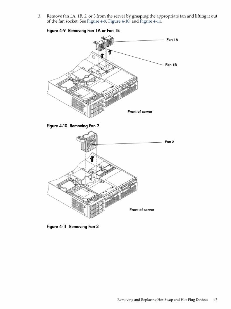
3. Remove fan 1A, 1B, 2, or 3 from the server by grasping the appropriate fan and lifting it outof the fan socket. See Figure 4-9, Figure 4-10, and Figure 4-11.
Figure 4-9 Removing Fan 1A or Fan 1B
Figure 4-10 Removing Fan 2
Figure 4-11 Removing Fan 3
Removing and Replacing Hot-Swap and Hot-Plug Devices 47
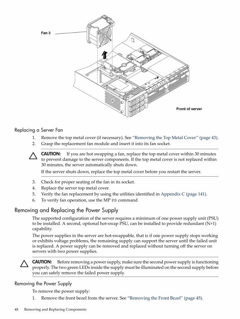
Replacing a Server Fan1. Remove the top metal cover (if necessary). See “Removing the Top Metal Cover” (page 43).2. Grasp the replacement fan module and insert it into its fan socket.
CAUTION: If you are hot swapping a fan, replace the top metal cover within 30 minutesto prevent damage to the server components. If the top metal cover is not replaced within30 minutes, the server automatically shuts down.If the server shuts down, replace the top metal cover before you restart the server.
3. Check for proper seating of the fan in its socket.4. Replace the server top metal cover.5. Verify the fan replacement by using the utilities identified in Appendix C (page 141).6. To verify fan operation, use the MP PS command
Removing and Replacing the Power SupplyThe supported configuration of the server requires a minimum of one power supply unit (PSU)to be installed. A second, optional hot-swap PSU, can be installed to provide redundant (N+1)capability.The power supplies in the server are hot-swappable, that is if one power supply stops workingor exhibits voltage problems, the remaining supply can support the server until the failed unitis replaced. A power supply can be removed and replaced without turning off the server onservers with two power supplies.
CAUTION: Before removing a power supply, make sure the second power supply is functioningproperly. The two green LEDs inside the supply must be illuminated on the second supply beforeyou can safely remove the failed power supply.
Removing the Power SupplyTo remove the power supply:1. Remove the front bezel from the server. See “Removing the Front Bezel” (page 45).
48 Removing and Replacing Components
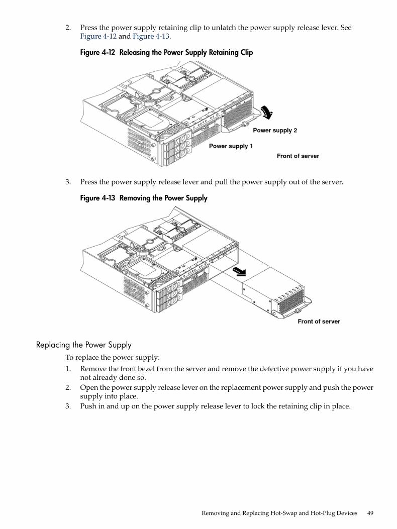
2. Press the power supply retaining clip to unlatch the power supply release lever. SeeFigure 4-12 and Figure 4-13.
Figure 4-12 Releasing the Power Supply Retaining Clip
3. Press the power supply release lever and pull the power supply out of the server.
Figure 4-13 Removing the Power Supply
Replacing the Power SupplyTo replace the power supply:1. Remove the front bezel from the server and remove the defective power supply if you have
not already done so.2. Open the power supply release lever on the replacement power supply and push the power
supply into place.3. Push in and up on the power supply release lever to lock the retaining clip in place.
Removing and Replacing Hot-Swap and Hot-Plug Devices 49

Figure 4-14 Replacing the Power Supply
4. Verify that both power supply LEDs, visible through the front of the supply grid, areilluminated.
5. Verify the power supply replacement by using the utilities identified in Appendix C(page 141).
6. To verify power supply operation, use the iLO MP PS command.7. Replace the front bezel.
Removing and Replacing an Internal Hard DriveThis section provides information about removing and replacing internal hard drives.The server supports up to three hot-pluggable, low-voltage differential (LVD) hard drives. Thesehard drives are 3.5-inch form factor devices that connect to Ultra 320 Wide LVD SCSI interfaceson the disk cage backplane.
CAUTION: Verify that the operating system supports installing disk drives while the operatingsystem is running. If the operating system does not support this feature, shut down the operatingsystem before attempting this procedure. Failure to observe this caution results in server failure.
Removing a Hard DriveTo remove a hard drive:1. If the server is powered on and the operating system is running, prepare the operating
system to have the hard drive removed. Shut down your operating system by followingyour operating system instructions.
50 Removing and Replacing Components
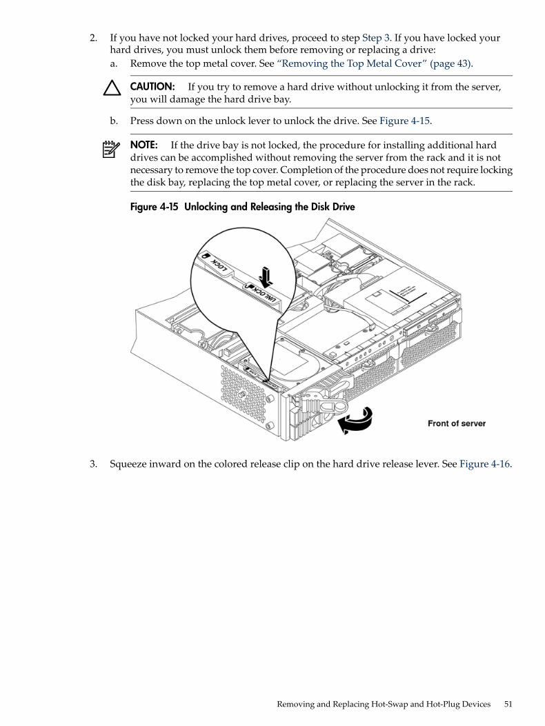
2. If you have not locked your hard drives, proceed to step Step 3. If you have locked yourhard drives, you must unlock them before removing or replacing a drive:a. Remove the top metal cover. See “Removing the Top Metal Cover” (page 43).
CAUTION: If you try to remove a hard drive without unlocking it from the server,you will damage the hard drive bay.
b. Press down on the unlock lever to unlock the drive. See Figure 4-15.
NOTE: If the drive bay is not locked, the procedure for installing additional harddrives can be accomplished without removing the server from the rack and it is notnecessary to remove the top cover. Completion of the procedure does not require lockingthe disk bay, replacing the top metal cover, or replacing the server in the rack.
Figure 4-15 Unlocking and Releasing the Disk Drive
3. Squeeze inward on the colored release clip on the hard drive release lever. See Figure 4-16.
Removing and Replacing Hot-Swap and Hot-Plug Devices 51

Figure 4-16 Releasing the Disk Drive
4. Pull outward on the release lever to remove the drive from the server. See Figure 4-17.
Figure 4-17 Removing the Disk Drive
Replacing a Hard DriveTo install or replace a hard drive:1. Insert the hard drive into the drive bay from which you removed the drive and push inward
on the release lever until the drive no long slides forward. You must leave the release leverin the open position when you push the drive into the server.
2. Release the lock on the drive being installed and swing the drive ejection handle to the openposition.
3. Slide the hard drive into the slot until it is nearly seated.
52 Removing and Replacing Components

4. Lock the hard drives in place. Replace the server top metal cover if it was removed to unlockdrives.
5. Validate the hard drive installation by:a. If the server does not have MP hardware installed, at the EFI shell prompt, enter shell>
info io to interrogate the server for proper identification of the drive.b. Use the Offline Diagnostic Environment (ODE) MAPPER to map the device and path for
the drive.c. Use the Offline Diagnostic Environment (ODE) PERFVER to perform self test on the
drive.6. Reset the server to the EFI Boot Maintenance Menu to rescan the hard drives.
Removing and Replacing Internal ComponentsTo upgrade, remove, or replace most server components, you must first shut down the server,and remove the top metal cover.
WARNING! Do not remove the server covers without first powering the server off andunplugging the power cord from the outlet or power protection device unless you are replacinga hot-swappable fan.When the server is running, you must replace the top metal cover within 30 minutes to preventcomponents from overheating. If the top metal cover is not replaced within 30 minutes, the serverautomatically shuts down. If the server shuts down, always replace the covers before turningthe server back on.
Memory and Processor Airflow GuidesThe server has the following airflow guides:• The processor airflow guide. See Figure 4-18• The memory airflow guide. See Figure 4-18Air flows through the server from front to back.
Figure 4-18 Airflow Guides Locations
Removing and Replacing the Memory Airflow GuideThe following procedures explain how to remove and replace the memory airflow guide.
Removing the Memory Airflow Guide1. Power off the server and disconnect all power cables. See “Powering Off the Server”
(page 37).
Removing and Replacing Internal Components 53
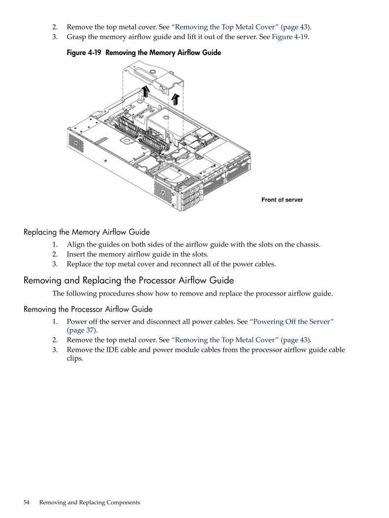
2. Remove the top metal cover. See “Removing the Top Metal Cover” (page 43).3. Grasp the memory airflow guide and lift it out of the server. See Figure 4-19.
Figure 4-19 Removing the Memory Airflow Guide
Replacing the Memory Airflow Guide1. Align the guides on both sides of the airflow guide with the slots on the chassis.2. Insert the memory airflow guide in the slots.3. Replace the top metal cover and reconnect all of the power cables.
Removing and Replacing the Processor Airflow GuideThe following procedures show how to remove and replace the processor airflow guide.
Removing the Processor Airflow Guide1. Power off the server and disconnect all power cables. See “Powering Off the Server”
(page 37).2. Remove the top metal cover. See “Removing the Top Metal Cover” (page 43).3. Remove the IDE cable and power module cables from the processor airflow guide cable
clips.
54 Removing and Replacing Components

4. Remove the main portion of the airflow guide:a. Hold the guide using the opening on top of the guide. See Figure 4-20.b. At the same time, grasp the back end of the airflow guide and lift the guide out of the
server.
Figure 4-20 Removing the Processor Airflow Guide
5. Disconnect the power cable connected to the guide from the system board.6. Remove the front portion of the airflow guide by doing the following:
a. Remove server fans 1A and 1B.b. Rotate the clip clockwise to release the latch. See Figure 4-21 and Figure 4-22.
Figure 4-21 Opening the Release Clip
Removing and Replacing Internal Components 55
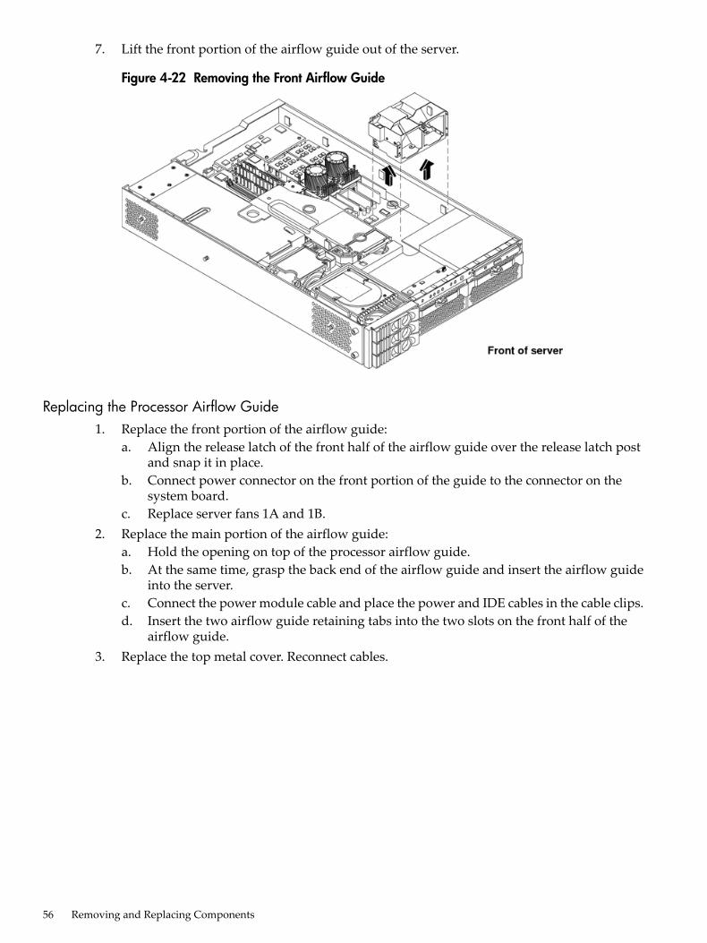
7. Lift the front portion of the airflow guide out of the server.
Figure 4-22 Removing the Front Airflow Guide
Replacing the Processor Airflow Guide1. Replace the front portion of the airflow guide:
a. Align the release latch of the front half of the airflow guide over the release latch postand snap it in place.
b. Connect power connector on the front portion of the guide to the connector on thesystem board.
c. Replace server fans 1A and 1B.2. Replace the main portion of the airflow guide:
a. Hold the opening on top of the processor airflow guide.b. At the same time, grasp the back end of the airflow guide and insert the airflow guide
into the server.c. Connect the power module cable and place the power and IDE cables in the cable clips.d. Insert the two airflow guide retaining tabs into the two slots on the front half of the
airflow guide.3. Replace the top metal cover. Reconnect cables.
56 Removing and Replacing Components
Removing and Replacing Memory DIMMsYour server has 12 memory sockets for installing DDR SDRAM memory DIMMs. The supportedDIMM sizes are 256 MB, 512 MB, 1 GB, 2 GB, or 4 GB. The server supports combinations from 1GB up to 32 GB. See Figure 4-23 for the DIMM slot locations on the system board.
WARNING! Ensure that the server is powered off, and all power sources have been disconnectedfrom the server before removing or replacing server memory.Voltages are present at various locations within the server when an AC power source is connected.This voltage is present even when the main power switch is in the off position.Failure to observe this warning could result in personal injury or damage to equipment.
CAUTION: Observe all ESD safety precautions before attempting this procedure. Failure tofollow ESD safety precautions could result in damage to the server.
Supported DIMM SizesSupported DIMM sizes are 256 MB, 512 MB, 1 GB, 2 GB, and 4 GB. Memory in the server isinstalled in quads. A quad of memory is a set of four matching DIMMs. Quad sizes can differwithin the server as long as all DIMMs within a quad match, unless you are installing 4 GBDIMMs. The only set up allowed with 4 GB DIMMs is to install eight 4 GB DIMMs. The serversupports combinations from 1 GB (using 256 MB DIMMs) to 32 GB (using eight 4 GB DIMMs).See Figure 4-23 for the identification of quads.
Removing and Replacing Internal Components 57
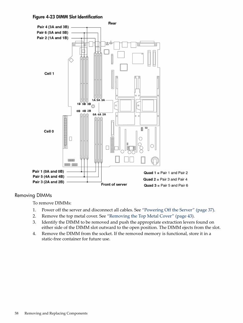
Figure 4-23 DIMM Slot Identification
Removing DIMMsTo remove DIMMs:1. Power off the server and disconnect all cables. See “Powering Off the Server” (page 37).2. Remove the top metal cover. See “Removing the Top Metal Cover” (page 43).3. Identify the DIMM to be removed and push the appropriate extraction levers found on
either side of the DIMM slot outward to the open position. The DIMM ejects from the slot.4. Remove the DIMM from the socket. If the removed memory is functional, store it in a
static-free container for future use.
58 Removing and Replacing Components
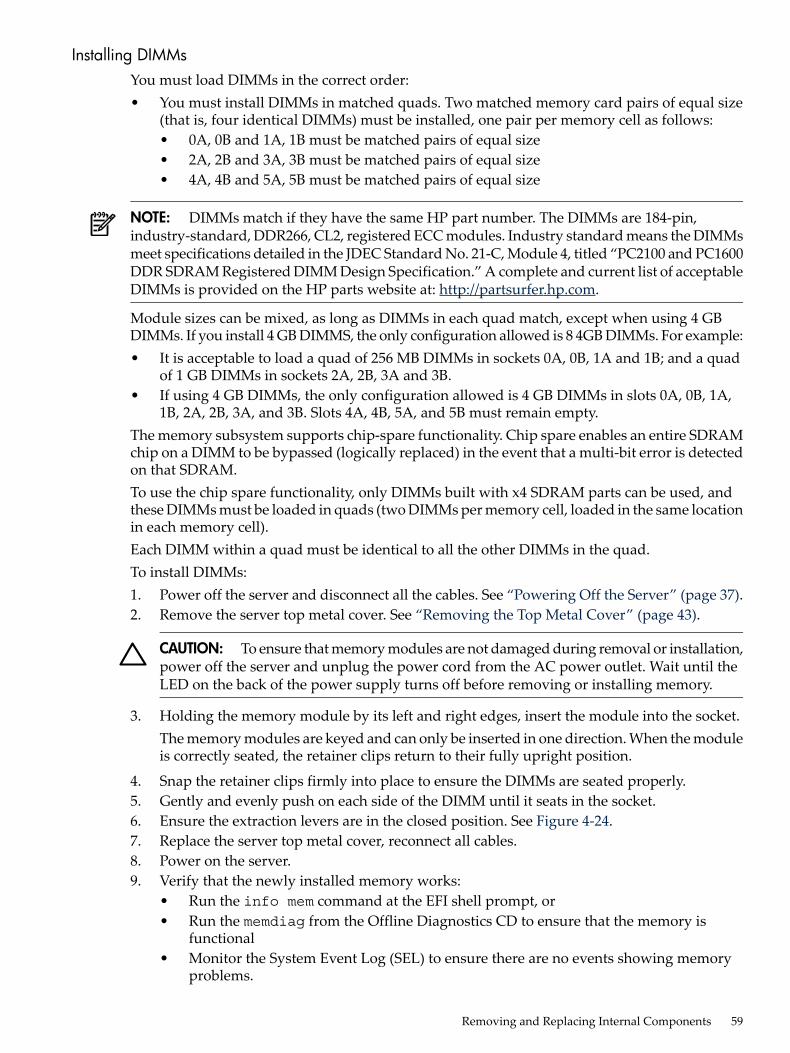
Installing DIMMsYou must load DIMMs in the correct order:• You must install DIMMs in matched quads. Two matched memory card pairs of equal size
(that is, four identical DIMMs) must be installed, one pair per memory cell as follows:• 0A, 0B and 1A, 1B must be matched pairs of equal size• 2A, 2B and 3A, 3B must be matched pairs of equal size• 4A, 4B and 5A, 5B must be matched pairs of equal size
NOTE: DIMMs match if they have the same HP part number. The DIMMs are 184-pin,industry-standard, DDR266, CL2, registered ECC modules. Industry standard means the DIMMsmeet specifications detailed in the JDEC Standard No. 21-C, Module 4, titled “PC2100 and PC1600DDR SDRAM Registered DIMM Design Specification.” A complete and current list of acceptableDIMMs is provided on the HP parts website at: http://partsurfer.hp.com.
Module sizes can be mixed, as long as DIMMs in each quad match, except when using 4 GBDIMMs. If you install 4 GB DIMMS, the only configuration allowed is 8 4GB DIMMs. For example:• It is acceptable to load a quad of 256 MB DIMMs in sockets 0A, 0B, 1A and 1B; and a quad
of 1 GB DIMMs in sockets 2A, 2B, 3A and 3B.• If using 4 GB DIMMs, the only configuration allowed is 4 GB DIMMs in slots 0A, 0B, 1A,
1B, 2A, 2B, 3A, and 3B. Slots 4A, 4B, 5A, and 5B must remain empty.The memory subsystem supports chip-spare functionality. Chip spare enables an entire SDRAMchip on a DIMM to be bypassed (logically replaced) in the event that a multi-bit error is detectedon that SDRAM.To use the chip spare functionality, only DIMMs built with x4 SDRAM parts can be used, andthese DIMMs must be loaded in quads (two DIMMs per memory cell, loaded in the same locationin each memory cell).Each DIMM within a quad must be identical to all the other DIMMs in the quad.To install DIMMs:1. Power off the server and disconnect all the cables. See “Powering Off the Server” (page 37).2. Remove the server top metal cover. See “Removing the Top Metal Cover” (page 43).
CAUTION: To ensure that memory modules are not damaged during removal or installation,power off the server and unplug the power cord from the AC power outlet. Wait until theLED on the back of the power supply turns off before removing or installing memory.
3. Holding the memory module by its left and right edges, insert the module into the socket.The memory modules are keyed and can only be inserted in one direction. When the moduleis correctly seated, the retainer clips return to their fully upright position.
4. Snap the retainer clips firmly into place to ensure the DIMMs are seated properly.5. Gently and evenly push on each side of the DIMM until it seats in the socket.6. Ensure the extraction levers are in the closed position. See Figure 4-24.7. Replace the server top metal cover, reconnect all cables.8. Power on the server.9. Verify that the newly installed memory works:
• Run the info mem command at the EFI shell prompt, or• Run the memdiag from the Offline Diagnostics CD to ensure that the memory is
functional• Monitor the System Event Log (SEL) to ensure there are no events showing memory
problems.
Removing and Replacing Internal Components 59

Figure 4-24 Inserting DIMM into Slot
60 Removing and Replacing Components

Removing and Replacing a ProcessorThis section provides information about removing and replacing a processor. The processors arelocated on the system board, which is accessible by removing the top metal cover.
WARNING! Ensure that the server is powered off, and all power sources have been disconnectedfrom the server before removing or replacing a processor.Voltages are present at various locations within the server when an AC power source is connected.This voltage is present even when the main power switch is in the off position.Failure to observe this warning could result in personal injury or damage to equipment
CAUTION: Failure to properly complete the steps in this procedure will result in erratic serverbehavior or server failure.Observe all ESD safety precautions before attempting this procedure. Failure to follow ESD safetyprecautions could result in damage to the server.
The processors are located on the system board. The system board can support either one or twoprocessors. The CPU 0 slot is located on the right side of the system board, and the CPU 1 slotis located to the left of CPU 0 near the DIMMs. For the processor locations, see Figure 4-25.
CAUTION: Ensure that the cache size is identical for all processors. Failure to observe thiscaution will result in server failure.Ensure that all processors are rated for use at the same speed. Failure to observe this caution willresult in performance degradation.Valid processors are identified in Appendix A (page 117).
NOTE: In a single processor configuration, the single processor must be installed in the CPU0 slot.
Removing and Replacing Internal Components 61
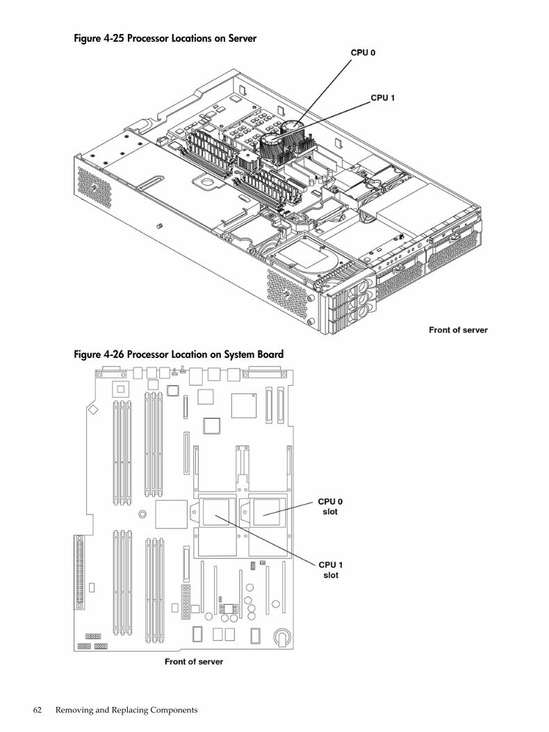
Figure 4-25 Processor Locations on Server
Figure 4-26 Processor Location on System Board
62 Removing and Replacing Components
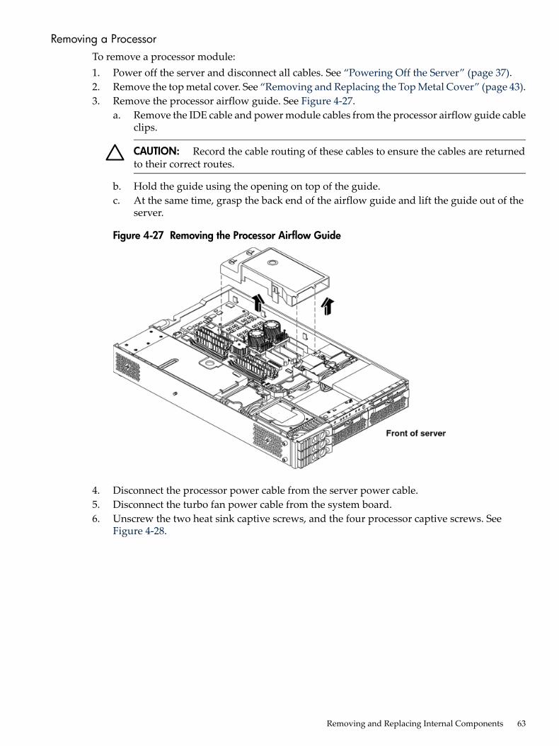
Removing a ProcessorTo remove a processor module:1. Power off the server and disconnect all cables. See “Powering Off the Server” (page 37).2. Remove the top metal cover. See “Removing and Replacing the Top Metal Cover” (page 43).3. Remove the processor airflow guide. See Figure 4-27.
a. Remove the IDE cable and power module cables from the processor airflow guide cableclips.
CAUTION: Record the cable routing of these cables to ensure the cables are returnedto their correct routes.
b. Hold the guide using the opening on top of the guide.c. At the same time, grasp the back end of the airflow guide and lift the guide out of the
server.
Figure 4-27 Removing the Processor Airflow Guide
4. Disconnect the processor power cable from the server power cable.5. Disconnect the turbo fan power cable from the system board.6. Unscrew the two heat sink captive screws, and the four processor captive screws. See
Figure 4-28.
Removing and Replacing Internal Components 63
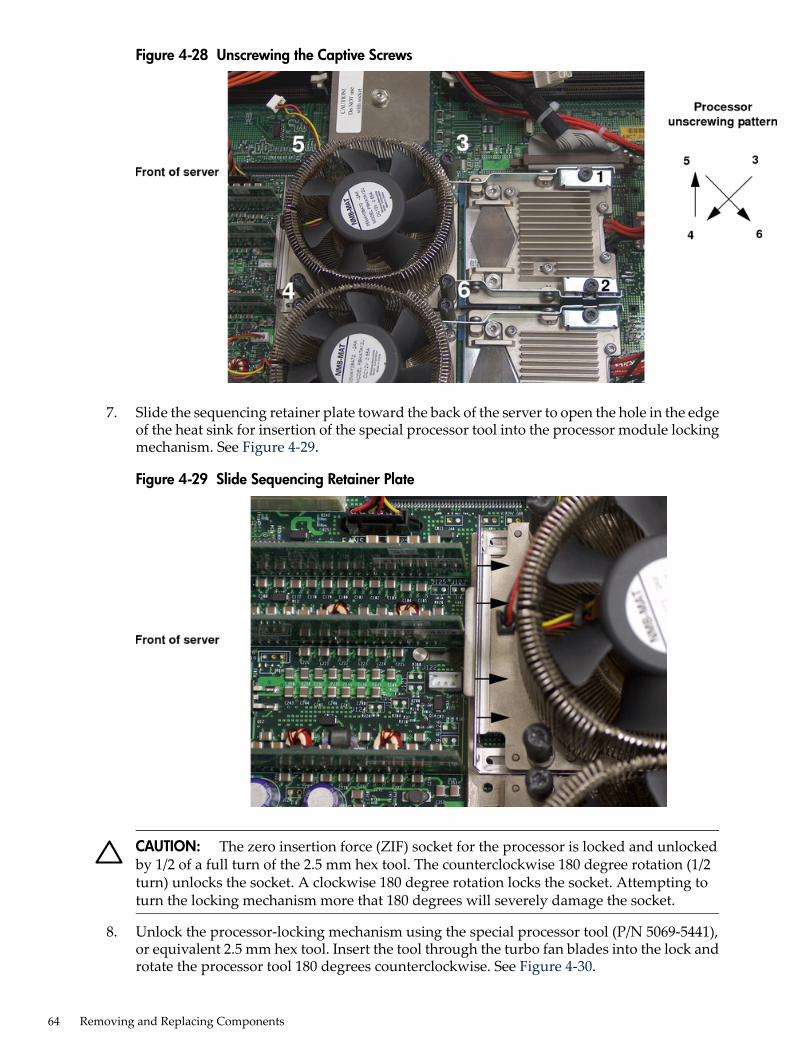
Figure 4-28 Unscrewing the Captive Screws
7. Slide the sequencing retainer plate toward the back of the server to open the hole in the edgeof the heat sink for insertion of the special processor tool into the processor module lockingmechanism. See Figure 4-29.
Figure 4-29 Slide Sequencing Retainer Plate
CAUTION: The zero insertion force (ZIF) socket for the processor is locked and unlockedby 1/2 of a full turn of the 2.5 mm hex tool. The counterclockwise 180 degree rotation (1/2turn) unlocks the socket. A clockwise 180 degree rotation locks the socket. Attempting toturn the locking mechanism more that 180 degrees will severely damage the socket.
8. Unlock the processor-locking mechanism using the special processor tool (P/N 5069-5441),or equivalent 2.5 mm hex tool. Insert the tool through the turbo fan blades into the lock androtate the processor tool 180 degrees counterclockwise. See Figure 4-30.
64 Removing and Replacing Components

Figure 4-30 Unlocking the Processor Module Locking Mechanism
9. Lift the processor up and out of the chassis. Place the processor module into an anti-staticcontainer.
Replacing a Processor
CAUTION: Do not modify the settings of the DIP switches located on the system board. Theseswitches are for factory use. Failure to observe this caution will result in server failure.
1. Power off the server and disconnect all cables. See “Powering Off the Server” (page 37).2. Remove the top metal cover. See “Removing and Replacing the Top Metal Cover” (page 43).3. If you are replacing a processor module, remove the old processor as described in “Removing
a Processor” (page 63).4. Verify the ZIF socket lock is unlocked. The thicker post on the locking mechanism must be
pointed toward the unlock symbol on the ZIF socket. Figure 4-33 shows the socket unlocked.
Removing and Replacing Internal Components 65

Figure 4-31 Unlocked ZIF Socket Lock
CAUTION: The zero insertion force (ZIF) socket for the processor is locked and unlockedby half a turn of the 2.5 mm hex tool. A counterclockwise 180 degree rotation (1/2 turn)unlocks the socket. A clockwise 180 degree rotation locks the socket. Attempting to turn thelocking mechanism more that 180 degrees in either direction will severely damage the socket.
5. Use the two alignment pins on the processor to properly align the processor on the systemboard. The two alignment pins fit in the alignment holes on the system board processormount. Figure 4-32 shows the location of the alignment pins on the processor. Figure 4-33shows the alignment holes on the system board. The turbo fan power cable must be positionedso that it is located on the side of the heat sink that faces the front of the server. Figure 4-34shows the processor on the system board.
Figure 4-32 Processor Alignment Pins
66 Removing and Replacing Components

Figure 4-33 CPU Slot Alignment Holes
Figure 4-34 Installing the Processor Module
CAUTION: Do not press the processor module into the socket. When properly aligned, theprocessor pins seat into the ZIF socket. No additional pressure is required.
6. Use the special processor tool shipped with the replacement processor module to lock theprocessor module in place on the system board. To do this, insert the special processor toolthrough the turbo fan blades into the ZIF socket. Rotate the tool clockwise 180 degrees. SeeFigure 4-35.
Removing and Replacing Internal Components 67
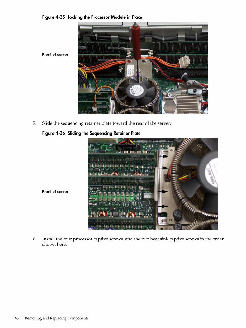
Figure 4-35 Locking the Processor Module in Place
7. Slide the sequencing retainer plate toward the rear of the server.
Figure 4-36 Sliding the Sequencing Retainer Plate
8. Install the four processor captive screws, and the two heat sink captive screws in the ordershown here.
68 Removing and Replacing Components
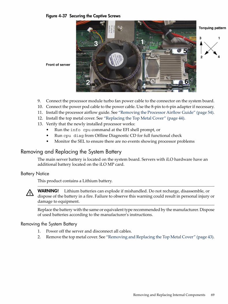
Figure 4-37 Securing the Captive Screws
9. Connect the processor module turbo fan power cable to the connector on the system board.10. Connect the power pod cable to the power cable. Use the 8-pin to 6-pin adapter if necessary.11. Install the processor airflow guide. See “Removing the Processor Airflow Guide” (page 54).12. Install the top metal cover. See “Replacing the Top Metal Cover” (page 44).13. Verify that the newly installed processor works:
• Run the info cpu command at the EFI shell prompt, or• Run cpu diag from Offline Diagnostic CD for full functional check• Monitor the SEL to ensure there are no events showing processor problems
Removing and Replacing the System BatteryThe main server battery is located on the system board. Servers with iLO hardware have anadditional battery located on the iLO MP card.
Battery NoticeThis product contains a Lithium battery.
WARNING! Lithium batteries can explode if mishandled. Do not recharge, disassemble, ordispose of the battery in a fire. Failure to observe this warning could result in personal injury ordamage to equipment.
Replace the battery with the same or equivalent type recommended by the manufacturer. Disposeof used batteries according to the manufacturer's instructions.
Removing the System Battery1. Power off the server and disconnect all cables.2. Remove the top metal cover. See “Removing and Replacing the Top Metal Cover” (page 43).
Removing and Replacing Internal Components 69
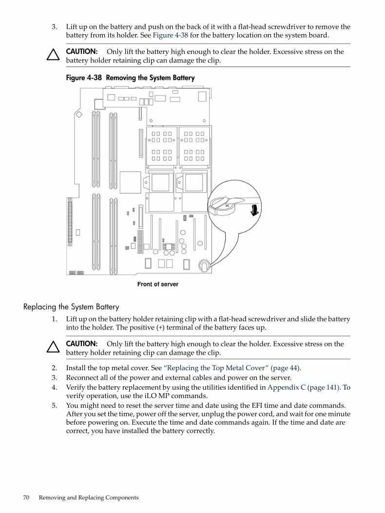
3. Lift up on the battery and push on the back of it with a flat-head screwdriver to remove thebattery from its holder. See Figure 4-38 for the battery location on the system board.
CAUTION: Only lift the battery high enough to clear the holder. Excessive stress on thebattery holder retaining clip can damage the clip.
Figure 4-38 Removing the System Battery
Replacing the System Battery1. Lift up on the battery holder retaining clip with a flat-head screwdriver and slide the battery
into the holder. The positive (+) terminal of the battery faces up.
CAUTION: Only lift the battery high enough to clear the holder. Excessive stress on thebattery holder retaining clip can damage the clip.
2. Install the top metal cover. See “Replacing the Top Metal Cover” (page 44).3. Reconnect all of the power and external cables and power on the server.4. Verify the battery replacement by using the utilities identified in Appendix C (page 141). To
verify operation, use the iLO MP commands.5. You might need to reset the server time and date using the EFI time and date commands.
After you set the time, power off the server, unplug the power cord, and wait for one minutebefore powering on. Execute the time and date commands again. If the time and date arecorrect, you have installed the battery correctly.
70 Removing and Replacing Components
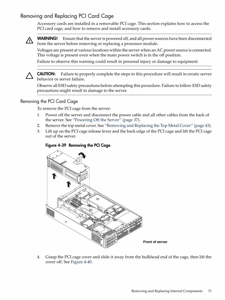
Removing and Replacing PCI Card CageAccessory cards are installed in a removable PCI cage. This section explains how to access thePCI card cage, and how to remove and install accessory cards.
WARNING! Ensure that the server is powered off, and all power sources have been disconnectedfrom the server before removing or replacing a processor module.Voltages are present at various locations within the server when an AC power source is connected.This voltage is present even when the main power switch is in the off position.Failure to observe this warning could result in personal injury or damage to equipment.
CAUTION: Failure to properly complete the steps in this procedure will result in erratic serverbehavior or server failure.Observe all ESD safety precautions before attempting this procedure. Failure to follow ESD safetyprecautions might result in damage to the server.
Removing the PCI Card CageTo remove the PCI cage from the server:1. Power off the server and disconnect the power cable and all other cables from the back of
the server. See “Powering Off the Server” (page 37).2. Remove the top metal cover. See “Removing and Replacing the Top Metal Cover” (page 43).3. Lift up on the PCI cage release lever and the back edge of the PCI cage and lift the PCI cage
out of the server.
Figure 4-39 Removing the PCI Cage
4. Grasp the PCI cage cover and slide it away from the bulkhead end of the cage, then lift thecover off. See Figure 4-40.
Removing and Replacing Internal Components 71
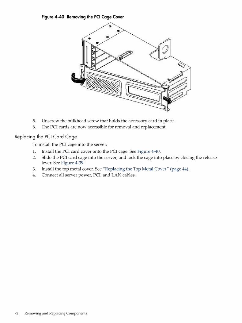
Figure 4-40 Removing the PCI Cage Cover
5. Unscrew the bulkhead screw that holds the accessory card in place.6. The PCI cards are now accessible for removal and replacement.
Replacing the PCI Card CageTo install the PCI cage into the server:1. Install the PCI card cover onto the PCI cage. See Figure 4-40.2. Slide the PCI card cage into the server, and lock the cage into place by closing the release
lever. See Figure 4-39.3. Install the top metal cover. See “Replacing the Top Metal Cover” (page 44).4. Connect all server power, PCI, and LAN cables.
72 Removing and Replacing Components
Removing and Replacing PCI CardsThe server can contain up to four PCI cards. PCI cards are located in the PCI cage.
CAUTION: There are restrictions on the number of PCI-X cards that can be installed in theserver at any given time, depending on the cards being used.Maximum quantity for any I/O configuration using 337972-B21, AB287A, or A9890A cards:• Three A9890A cards maximum and one unpopulated slot• Two 337972-B21 cards maximum and two unpopulated slots• One AB287A card maximum and three unpopulated slotsFailure to observe this caution results in server degradation or server failure.
The server has the following accessory card sockets:• Four 64-bit, 133 MHz PCI-X card sockets
WARNING! Ensure that the server is off, and all power sources have been disconnected fromthe server before removing or replacing a PCI card.Voltages are present at various locations within the server when an AC power source is connected.This voltage is present even when the main power switch is in the off position.Failure to observe this warning could result in personal injury or damage to equipment.
CAUTION: Observe all ESD safety precautions before attempting this procedure. Failure tofollow ESD safety precautions could result in damage to the server.
Carefully read the following information concerning PCI slot configuration. Inserting a PCI cardinto a slot that is not configured to accept it, can cause operation failure or the PCI card to operateat less than optimum speed. PCI slots are numbered 1 (top of cage) through 4 (bottom of cage).See the labels on the rear panel of the chassis for correct PCI slot number identification.
Removing a PCI CardTo remove a PCI card from the server:
CAUTION: Record the location of all PCI cards as they are installed. Depending on the operatingsystem, replacing the PCI card in a different location might cause boot failure.
1. Power off the server and disconnect the power cable and all other cables from the back ofthe server. See “Powering Off the Server” (page 37).
2. Remove the top metal cover. See “Removing and Replacing the Top Metal Cover” (page 43).3. Disconnect any cables that are connected to the PCI card to remove the PCI cage.4. Perform the procedure for removing the PCI cage described in the previous section.5. Grasp the edges of the PCI card being removed and gently rock the card releasing the
connector from the PCI backplane connector. Place the removed PCI card in an electrostaticcontainer.
Removing and Replacing Internal Components 73
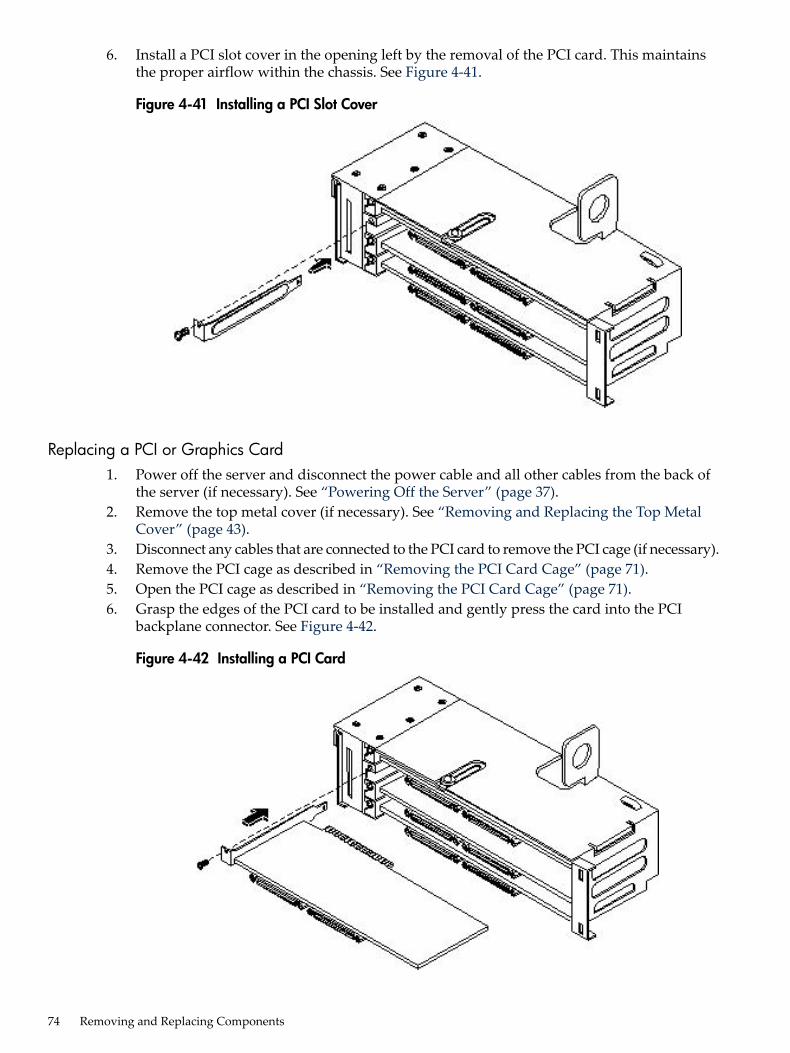
6. Install a PCI slot cover in the opening left by the removal of the PCI card. This maintainsthe proper airflow within the chassis. See Figure 4-41.
Figure 4-41 Installing a PCI Slot Cover
Replacing a PCI or Graphics Card1. Power off the server and disconnect the power cable and all other cables from the back of
the server (if necessary). See “Powering Off the Server” (page 37).2. Remove the top metal cover (if necessary). See “Removing and Replacing the Top Metal
Cover” (page 43).3. Disconnect any cables that are connected to the PCI card to remove the PCI cage (if necessary).4. Remove the PCI cage as described in “Removing the PCI Card Cage” (page 71).5. Open the PCI cage as described in “Removing the PCI Card Cage” (page 71).6. Grasp the edges of the PCI card to be installed and gently press the card into the PCI
backplane connector. See Figure 4-42.
Figure 4-42 Installing a PCI Card
74 Removing and Replacing Components

7. Reinstall the PCI cage. See “Replacing the PCI Card Cage” (page 72).8. Connect any cables that are required by the PCI card.9. Power on the server. See “Powering On the Server” (page 38).10. Verify the installation of all PCI cards:
• Look at the LEDs of all PCI cards for proper operation. See accessory manuals.• RunPERFVER from the Offline Diagnostics CD to ensure that all PCI cards are identified.• Monitor the SEL to ensure there are no events showing peripheral problems.
11. Replace the top metal cover. See “Removing and Replacing the Top Metal Cover” (page 43).12. Connect all server power, PCI, and LAN cables.
Removing and Replacing the PCI BackplaneThe server backplane is called the PCI backplane and provides four PCI card sockets.
Removing the PCI Backplane1. Remove all accessory and graphics cards.2. Unscrew the backplane mounting screws and slide the backplane board toward the bulkhead
end of the PCI cage. This unlocks the backplane from its standoffs.3. Lift the backplane over the top of the standoffs and slide it out of the cage.
Figure 4-43 Removing the PCI Backplane
Replacing the PCI Backplane1. Place the backplane in the cage by aligning the cage standoffs with the holes on the backplane
and sliding it into place.2. Secure the PCI backplane by screwing in its mounting screws.
Removing and Replacing Internal Components 75

Figure 4-44 Replacing the PCI Backplane
3. Replace any accessory and graphics cards.4. Connect server power, PCI, and LAN cables.5. Power on the server. See “Powering On the Server” (page 38).6. Verify the installation of the PCI backplane:
• Look at the LEDs of all PCI cards for proper operation.• Run mapper from the Offline Diagnostics CD to ensure that all PCI cards are identified.• Monitor the SEL to ensure there are no events showing peripheral problems.
Removing and Replacing a Removable Media DriveThe removable media drive is located behind the front bezel.
WARNING! Ensure that the server is off, and all power sources have been disconnected fromthe server before removing or replacing a removable media drive.Voltages are present at various locations within the server when an AC power source is connected.This voltage is present even when the main power switch is in the off position.Failure to observe this warning could result in personal injury or damage to equipment.
CAUTION: Observe all ESD safety precautions before attempting this procedure. Failure tofollow ESD safety precautions could result in damage to the server. Failure to properly completethe steps in this procedure will result in erratic server behavior or server failure.
Removing a Removable Media DriveTo remove a removable media drive:1. Power off the server and disconnect all cables. See “Powering Off the Server” (page 37).2. Remove the top metal cover. See “Removing and Replacing the Top Metal Cover” (page 43).3. Disconnect the IDE cable from the back of the drive. See Figure 4-45.4. Grasp the front of the DVD drive and squeeze in on the locking tab to release the drive.5. Pull the drive straight out to remove it from the chassis.
76 Removing and Replacing Components
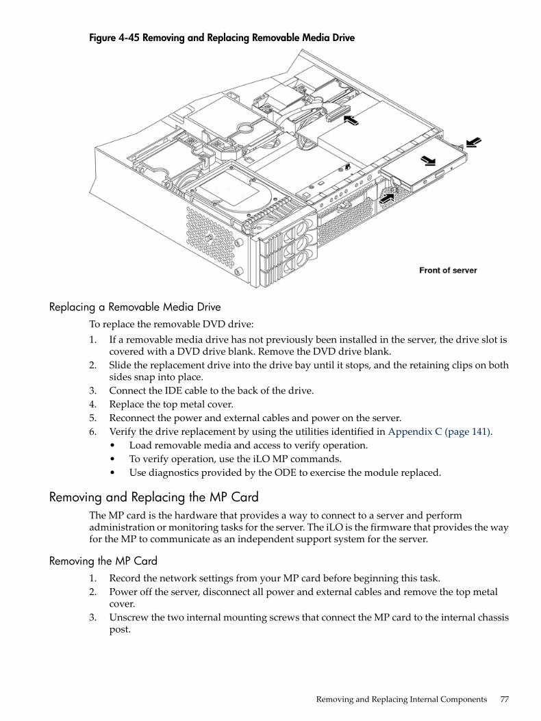
Figure 4-45 Removing and Replacing Removable Media Drive
Replacing a Removable Media DriveTo replace the removable DVD drive:1. If a removable media drive has not previously been installed in the server, the drive slot is
covered with a DVD drive blank. Remove the DVD drive blank.2. Slide the replacement drive into the drive bay until it stops, and the retaining clips on both
sides snap into place.3. Connect the IDE cable to the back of the drive.4. Replace the top metal cover.5. Reconnect the power and external cables and power on the server.6. Verify the drive replacement by using the utilities identified in Appendix C (page 141).
• Load removable media and access to verify operation.• To verify operation, use the iLO MP commands.• Use diagnostics provided by the ODE to exercise the module replaced.
Removing and Replacing the MP CardThe MP card is the hardware that provides a way to connect to a server and performadministration or monitoring tasks for the server. The iLO is the firmware that provides the wayfor the MP to communicate as an independent support system for the server.
Removing the MP Card1. Record the network settings from your MP card before beginning this task.2. Power off the server, disconnect all power and external cables and remove the top metal
cover.3. Unscrew the two internal mounting screws that connect the MP card to the internal chassis
post.
Removing and Replacing Internal Components 77

Figure 4-46 Removing the MP Card
4. Unscrew the two external mounting screws that are located on both sides of the 25-pin serialconnector as shown in Figure 4-47.
5. Disconnect the MP card connector.6. Remove the MP card from the server by grasping it by its edges.7. Install the MP blank (if not reinstalling the MP card) on the chassis. This blank is used to fill
the holes left by the 10/100 management LAN, 15-pin VGA and 25-pin serial connectors.See Figure 4-47.
Figure 4-47 Replacing the MP Blank
8. Push the MP blank against the inside of the chassis and Install the blank mounting screwon the external connector side of the server chassis.
78 Removing and Replacing Components
9. Replace the top metal cover and reconnect the power and external cables.
Replacing the MP Card1. Record the network settings from your iLO MP before beginning this task.2. Power off the server, disconnect all power and external cables, and remove the top metal
cover.3. If you are installing a new MP card, remove the MP blank.4. Unscrew the mounting screw for the MP blank, located on the external connector side of
the server chassis.5. Remove the blank retaining tab from its socket on the server chassis and remove the blank
from the server.6. Insert the MP card in the server.7. Grasp its edges and place it on the two MP posts.8. Push the 10/100 management LAN, 15-pin VGA and 25-pin serial connectors through their
openings on the back of the server9. Connect the MP card:
a. Connect the MP card cable to its connector on the system board.b. Install the two mounting screws that connect the MP card to the internal chassis post.c. Install the two external mounting screws that are located on both sides of the 25-pin
serial connector.10. Replace the MP hardware connector.11. Verify the MP card replacement by using the utilities identified in Appendix C (page 141).
To verify operation, use the iLO MP commands.
Removing and Replacing the MP Card BatterySystems with an MP card have two batteries. Systems without MP hardware have only onebattery. The main server battery is located on the system board. The MP battery is located on theMP hardware.
Battery NoticeThis product contains a Lithium battery.
WARNING! Lithium batteries can explode if mishandled. Do not recharge, disassemble, ordispose of the battery in a fire. Failure to observe this warning might result in personal injuryor damage to equipment.
Replace only with the same or equivalent type recommended by the manufacturer. Dispose ofused batteries according to the manufacturer's instructions.
Removing the MP Card Battery1. Record the iLO MP configuration settings.2. Perform all of the steps described in the procedure for “Removing and Replacing the MP
Card” (page 77).3. The battery for the MP card is located on the underside of the board.
Removing and Replacing Internal Components 79
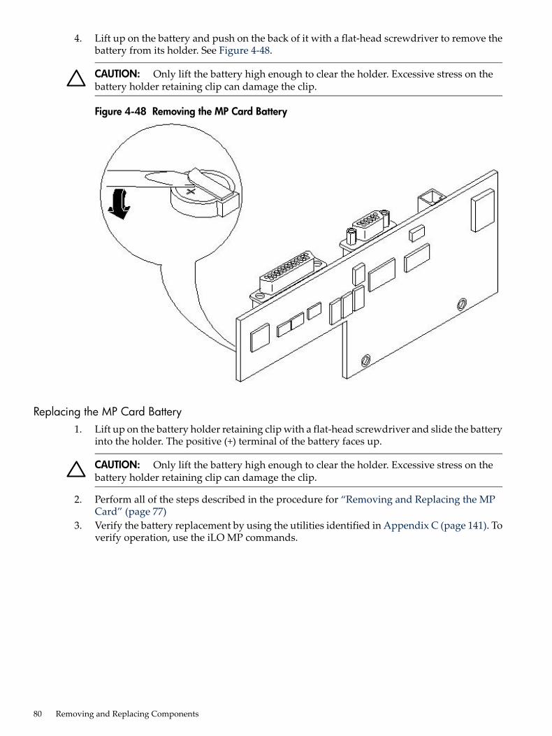
4. Lift up on the battery and push on the back of it with a flat-head screwdriver to remove thebattery from its holder. See Figure 4-48.
CAUTION: Only lift the battery high enough to clear the holder. Excessive stress on thebattery holder retaining clip can damage the clip.
Figure 4-48 Removing the MP Card Battery
Replacing the MP Card Battery1. Lift up on the battery holder retaining clip with a flat-head screwdriver and slide the battery
into the holder. The positive (+) terminal of the battery faces up.
CAUTION: Only lift the battery high enough to clear the holder. Excessive stress on thebattery holder retaining clip can damage the clip.
2. Perform all of the steps described in the procedure for “Removing and Replacing the MPCard” (page 77)
3. Verify the battery replacement by using the utilities identified in Appendix C (page 141). Toverify operation, use the iLO MP commands.
80 Removing and Replacing Components

Removing and Replacing the LED Status PanelThe LED status panel card contains the server and diagnostic LEDs.
CAUTION: Some server settings are saved to the LED status panel. If you are replacing boththe LED status panel and the system board, you must replace them one at a time to avoid lossof server settings.
Removing the LED Status Panel
IMPORTANT: First replace one component, then power on the server and boot to the EFI prompt.After confirming that the first component has been replaced successfully, shut off the server andreplace the second component.
1. Power off the server, disconnect all power cables, and remove the top metal cover.2. Disconnect the LED status panel controller cable.3. Unscrew the two LED status panel mounting screws and remove the panel. See Figure 4-49.
Figure 4-49 Removing the LED Status Panel
Replacing the LED Status Panel1. Replace the LED status panel in the server and install the two LED status panel mounting
screws.2. Connect the LED status panel controller cable.3. Replace the top metal cover and reconnect all power cables. Power on the server and verify
that the server and power LEDs illuminate.4. Copy a valid UUID to the new status panel.5. Verify the display panel replacement by exercising all front panel controls and observing
that the display panel LEDs are operating properly.
Removing and Replacing Internal Components 81

Removing and Replacing the System Board
CAUTION: Some server settings are saved to the LED status panel. If you are replacing boththe LED status panel and the system board, you must replace them one at a time to avoid lossof server settings.
Removing the System Board
IMPORTANT: First replace one component, then power on the server and boot to the EFI prompt.After confirming that the first component has been replaced successfully, shut down the serverand replace the second component.
1. Power off the server, disconnect all power and external cables and remove the top metalcover.
2. Remove the following components from the system board:• Memory airflow guide. See “Removing the Memory Airflow Guide” (page 53)• Memory DIMMs. See “Removing DIMMs” (page 58)• Processor airflow guide. See “Removing the Processor Airflow Guide” (page 54)• Processors. See “Removing a Processor” (page 63)• Server fans 1A, 1B, 2, and 3. See “Removing a Server Fan” (page 46)• PCI card cage. See “Removing the PCI Card Cage” (page 71)
3. If the server has iLO MP hardware installed, remove it as described in “Removing the MPCard” (page 77).
4. Remove the power connector plate:a. Unscrew the two power connector mounting screws on the back of the server.b. Remove the power connectors from the socket.
5. Unscrew the six backplane system board mounting screws that connect the system boardto the rear of the server chassis. See Figure 4-50.
Figure 4-50 Removing the System Board Mounting Screws
6. Disconnect all cables that are connected to the system board. To help with reassembly, notewhich cables were connected to which port.
82 Removing and Replacing Components

NOTE: To access the three power cables near the PCI cage, you must lift up the connectorbridge for the PCI cage fan.
7. Unscrew the system board mounting screw. A screw symbol is adjacent to the mountingscrew. See Figure 4-51.
Figure 4-51 Removing the System Board Mounting Screw
8. Remove the system board:a. Grasp the memory controller chip heat sink and slide the system board toward the front
of the server.b. Lift up the processor module side of the system board and slide it free of the PCI cage
bay. See Figure 4-52.
Figure 4-52 Removing the System Board
Replacing the System Board1. Remove the old system board.
Removing and Replacing Internal Components 83
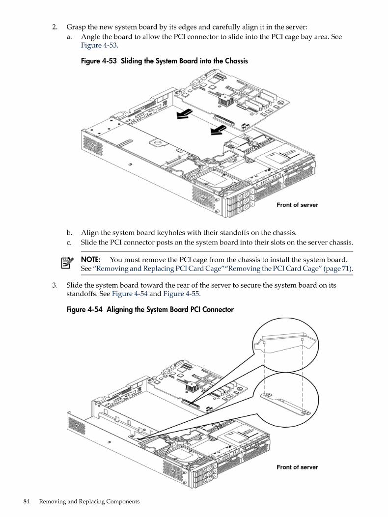
2. Grasp the new system board by its edges and carefully align it in the server:a. Angle the board to allow the PCI connector to slide into the PCI cage bay area. See
Figure 4-53.
Figure 4-53 Sliding the System Board into the Chassis
b. Align the system board keyholes with their standoffs on the chassis.c. Slide the PCI connector posts on the system board into their slots on the server chassis.
NOTE: You must remove the PCI cage from the chassis to install the system board.See “Removing and Replacing PCI Card Cage”“Removing the PCI Card Cage” (page 71).
3. Slide the system board toward the rear of the server to secure the system board on itsstandoffs. See Figure 4-54 and Figure 4-55.
Figure 4-54 Aligning the System Board PCI Connector
84 Removing and Replacing Components
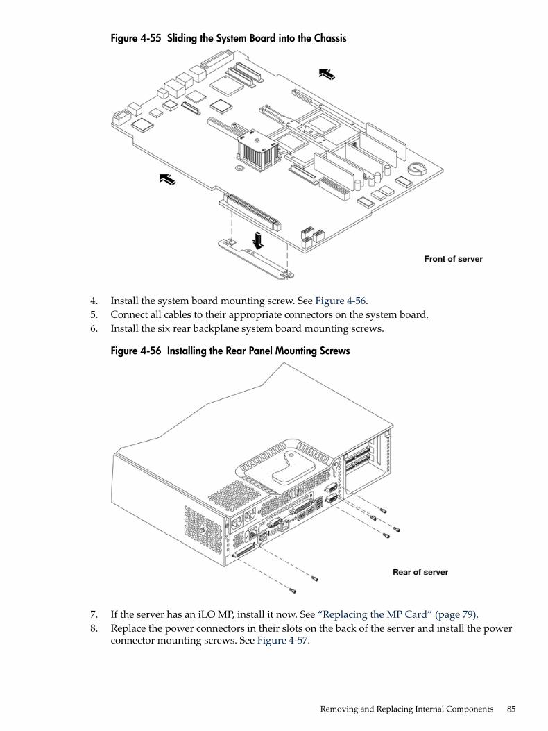
Figure 4-55 Sliding the System Board into the Chassis
4. Install the system board mounting screw. See Figure 4-56.5. Connect all cables to their appropriate connectors on the system board.6. Install the six rear backplane system board mounting screws.
Figure 4-56 Installing the Rear Panel Mounting Screws
7. If the server has an iLO MP, install it now. See “Replacing the MP Card” (page 79).8. Replace the power connectors in their slots on the back of the server and install the power
connector mounting screws. See Figure 4-57.
Removing and Replacing Internal Components 85
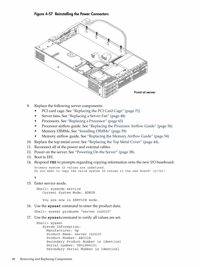
Figure 4-57 Reinstalling the Power Connectors
9. Replace the following server components:• PCI card cage. See “Replacing the PCI Card Cage” (page 72)• Server fans. See “Replacing a Server Fan” (page 48)• Processors. See “Replacing a Processor” (page 65)• Processor airflow guide. See “Replacing the Processor Airflow Guide” (page 56)• Memory DIMMs. See “Installing DIMMs” (page 59)• Memory airflow guide. See “Replacing the Memory Airflow Guide” (page 54)
10. Replace the top metal cover. See “Replacing the Top Metal Cover” (page 44).11. Reconnect all of the power and external cables.12. Power on the server. See “Powering On the Server” (page 38).13. Boot to EFI.14. Respond YES to prompts regarding copying information onto the new I/O baseboard.
Primary system ID values are undefined. Do you want to copy the valid system ID values to the new board? (y/[n])
Y
15. Enter service mode. Shell> sysmode service Current System Mode: ADMIN
You are now in SERVICE mode.
16. Use the sysset command to enter the product data:Shell> sysset prodname "server rx2620"
17. Use the syssetcommand to verify all values are set: Shell> sysset System Information: Manufacturer: hp Product Name: server rx2620 Product Number: AB332A Secondary Product Number is Identical Serial number: US51884101 Secondary Serial Number is Identical
86 Removing and Replacing Components
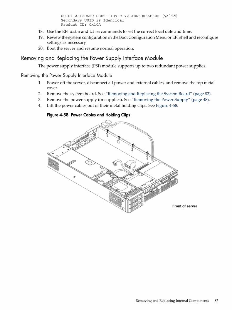
UUID: A8F2D6EC-DBE5-11D9-9172-AE65D056B60F (Valid) Secondary UUID is Identical Product ID: 0x10A
18. Use the EFI date and time commands to set the correct local date and time.19. Review the system configuration in the Boot Configuration Menu or EFI shell and reconfigure
settings as necessary.20. Boot the server and resume normal operation.
Removing and Replacing the Power Supply Interface ModuleThe power supply interface (PSI) module supports up to two redundant power supplies.
Removing the Power Supply Interface Module1. Power off the server, disconnect all power and external cables, and remove the top metal
cover.2. Remove the system board. See “Removing and Replacing the System Board” (page 82).3. Remove the power supply (or supplies). See “Removing the Power Supply” (page 48).4. Lift the power cables out of their metal holding clips. See Figure 4-58.
Figure 4-58 Power Cables and Holding Clips
Removing and Replacing Internal Components 87
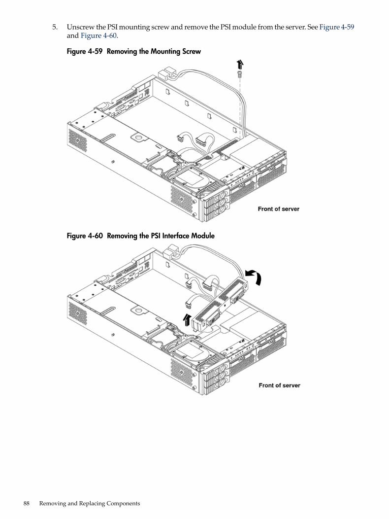
5. Unscrew the PSI mounting screw and remove the PSI module from the server. See Figure 4-59and Figure 4-60.
Figure 4-59 Removing the Mounting Screw
Figure 4-60 Removing the PSI Interface Module
88 Removing and Replacing Components
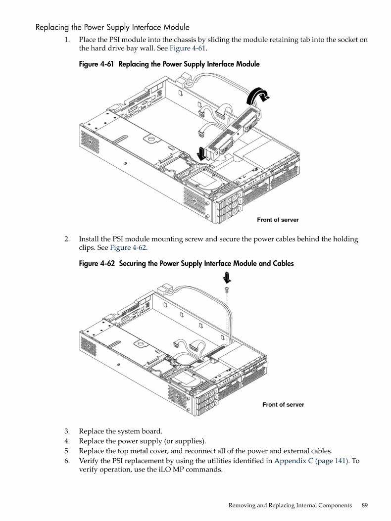
Replacing the Power Supply Interface Module1. Place the PSI module into the chassis by sliding the module retaining tab into the socket on
the hard drive bay wall. See Figure 4-61.
Figure 4-61 Replacing the Power Supply Interface Module
2. Install the PSI module mounting screw and secure the power cables behind the holdingclips. See Figure 4-62.
Figure 4-62 Securing the Power Supply Interface Module and Cables
3. Replace the system board.4. Replace the power supply (or supplies).5. Replace the top metal cover, and reconnect all of the power and external cables.6. Verify the PSI replacement by using the utilities identified in Appendix C (page 141). To
verify operation, use the iLO MP commands.
Removing and Replacing Internal Components 89

Removing and Replacing the Hard Drive SCSI Backplane
Removing the Hard Drive SCSI Backplane1. Power off the server, disconnect all power and external cables, and remove the top metal
cover.2. Lift up on the PCI cage release lever and the back edge of the PCI cage and lift the PCI cage
out of the server.3. Lift up on the fan power bridge and disconnect the backplane power cable. See Figure 4-63.
Figure 4-63 Opening the Fan Power Bridge
4. Remove any installed hard drives.5. Disconnect the SCSI cables and unscrew the backplane mounting screws. See Figure 4-64
and Figure 4-65.
Figure 4-64 Disconnecting SCSI Cables
90 Removing and Replacing Components
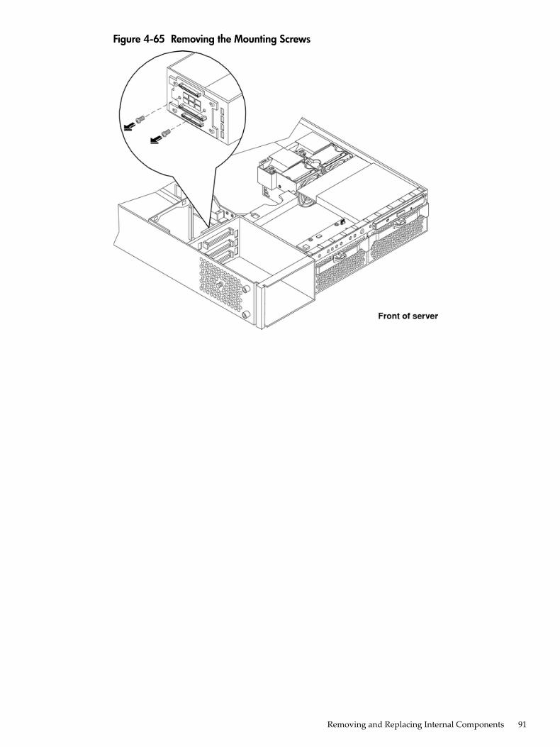
Figure 4-65 Removing the Mounting Screws
Removing and Replacing Internal Components 91

6. Remove the hard drive backplane by sliding it in the direction of the arrow and pulling itoutward from its standoff posts. See Figure 4-66 and Figure 4-67.
Figure 4-66 Removing the Backplane
Figure 4-67 Removing the Backplane from the Chassis
Replacing the Hard Drive SCSI Backplane1. Insert the hard drive backplane into its four chassis standoffs and slide it to the left. This
locks the hard drive backplane in place.2. Install the two backplane mounting screws and connect the two SCSI cables.3. Replace any removed hard drives.4. Connect the backplane power cable and lower the fan power bridge until it snaps in place.5. Replace the PCI cage in the server and secure it.6. Replace the top metal cover, and reconnect all of the power and external cables.
92 Removing and Replacing Components

7. Verify the backplane replacement by using the utilities identified in Appendix C (page 141).To verify operation, use the iLO MP commands.
Removing and Replacing Internal Components 93

94
5 TroubleshootingThis chapter provides troubleshooting instructions for maintaining the server.
Troubleshooting Tips
CAUTION: Do not operate the server for more than 30 minutes with any cover (including diskdrives) removed. Damage to server components can result due to improper cooling airflow.If you do not replace the top cover within 30 minutes, the server automatically shuts off.
• For problems with an optional disk array controller board, refer to the appropriate manualsprovided with the array controller.
• For general information on HP server products, see the HP website at http://www.hp.com.
Possible IssuesThis section contains example server problems and their possible solutions. For details on theiLO MP commands, see the HP Integrity and HP 9000 iLO Operations Guide.
The System Does Not Power-On1. Review the installation procedures for the server.2. Check all power connection cables.3. Verify that the Power On/Off LED on the control panel is illuminated. If not illuminated
check the AC power. If the LED is flashing yellow, the server is in DC standby. Check thepower status with the iLO MP PS command. If the Power On/Off LED is illuminated steadygreen, the DC power supply is on.
4. Check the normal operation of the power supply and fans. The iLO MP PS commandinterrogates the status of the power subsystem.
5. Check the system board diagnostic LEDs for proper operation. See System Board DiagnosticLEDs later in this chapter.
6. Verify that both LEDs of the power supply (visible behind bezel) are illuminated. The upperLED indicates presence of proper AC voltage, and the lower indicates that the DC power isgood.
7. Verify that all cables and modules are correctly connected. Check the display panelconnection. Use the iLO MPVFP command to verify a match of control panel LED indications.
8. If the server starts to power on and then power off, a voltage rail of the power supply mightbe out of specification. The BMC monitors voltages and prevents power on when powervalues are out of specification. If this occurs, check the SEL logs for an alert with a high level(alert level 5 or alert level 7). Also check the power subsystem with the iLO MP PS command.
The System Does Not Boot1. Examine the display panel LEDs for warning or fault indications. The server LED flashes
yellow with a warning indication and flashes red with a fault indication. If this occurs, checkthe SEL logs for additional information on the alert.
2. Examine the four diagnostic LEDs for specific warning or fault indications. The diagnosticLEDs present patterns that categorize the source of the warning or fault. This informationis also presented in the SEL.
Troubleshooting Tips 95
NOTE: If MP hardware is installed, the diagnostic LEDs are monitored by iLO. Thediagnostic LEDs on the control panel are disabled.
3. Display and examine the SEL and Forward Progress Log (FPL) for more information aboutwarning or fault indication.
4. Use the BMC CLI to cycle the server power, cli>pc off, cli>pc on. You can also usethe iLO MP PC command (pc -cycle -nc).
5. Remove all power from the server by disconnecting the AC power cords, wait at least twentyseconds, then reconnect the power cords and turn the server back on to see if the failure canbe cleared.
6. Check server memory for possible problems. You can also use the EFI info mem command.7. Check server processors for possible problems. You can also use the EFIinfo cpu command.
Or, by using the iLO MP SS command.8. Check the boot order in the Boot Configuration menu.9. If the server still does not boot, you might need to replace the base unit.
The System Has Intermittent Failures1. Examine the display panel LEDs for warning or fault indications. The server LED flashes
yellow with a warning indication and flashes red with a fault indication.2. Examine the four diagnostic LEDs for specific warning or fault indications. The diagnostic
LEDs present patterns that categorize the source of the warning or fault.
NOTE: If iLO MP hardware is installed, the boot process is monitored by the iLO MP. Thediagnostic LEDs are disabled.
3. Display and examine the SEL and FPL for more information about warning or fault indication.4. Make sure that the server fan assemblies are fully seated.5. Verify that the server is plugged into a power source that is within specifications described
on the label of the power supply.6. Make sure that the internal SCSI chain is terminated and termination is not enabled on any
drive. With LVD SCSI, termination is provided in the cable.7. Check that the processors are installed in the correct sockets, and terminators are installed
in all unused sockets.8. Reseat the main memory DDR DIMMs.9. If date and time or customer settings are cleared, you might need to replaced the system
board battery.
The System LED or Diagnostic LEDs are Not On, and No Error Messages AppearIf the server does not work (with no LEDs illuminated) and no error messages appear, check thefollowing:1. Make sure that all cables and the AC power cord are plugged into their proper receptacles.2. Make sure that the AC outlet is working. If the server is plugged into a switched
multiple-outlet box, make sure that the switch on the outlet box is turned on.3. Make sure that the server is turned on (the power-on light should be green and the fans
should be on).4. Turn the server off, wait at least twenty seconds, then turn the server back on to see if the
failure can be cleared.5. Make sure that all boards are installed properly and the processors are installed in the correct
slot. They must be seated firmly in their slots and any cables must be connected firmly.
96 Troubleshooting

6. If the server stopped working after you installed a new board, remove the board and poweron the server. If your server now works, check the installation instructions received withthe new board for correct installation method. If the new board is preventing the server frompowering on, a serious electrical problem is likely.
7. If the server still does not work, remove all boards and options that you have installed (donot remove the hard drives) and power on the server.
8. Add the boards and options one at a time to determine which one is causing the problem.9. If you have added any memory, make sure that the DDR DIMMs are seated properly in the
board. Also check the DDR DIMM configuration, and that the DDR DIMMs are matchedquads.
The Server Powers Off but Does Not RestartWhen certain critical conditions exist, the server shuts off all power.The critical conditions that can shut off the server include:• critical temperature fluctuations or changes• voltage problems (external AC line)• power supply failureIf the server powers off, and before you try a restart, do the following:1. Examine the display panel LEDs for warning or fault indications. The server LED flashes
yellow with a warning indication and flashes red with a fault indication.2. Examine the four diagnostic LEDs for indications of specific warning or fault indications.
The diagnostic LEDs present patterns that categorize the source of the warning or fault.
NOTE: If MP hardware is installed, the boot process is monitored by the iLO MP. Thediagnostic LEDs are disabled.
3. Display and examine the SEL and FPL for further information about warning or faultindication.
4. Make sure power is getting to the server. Plug a known working device into the poweroutlet.
5. Check for proper ventilation for the server. The server should have at least three inches ofspace around the front and rear for proper airflow when installed in a rack.
NOTE: A fluctuating power supply might cause temperature issues.
6. Check the server specifications and make sure the environmental temperature and voltageare within the specified guidelines.
7. Monitor the server to make sure you are not experiencing further temperature and voltageproblems.
Troubleshooting and FRU identificationAfter you have determined the current server state, you must troubleshoot the server to determinewhat repair to make.Use Table 5-1 to assist you in repairing the server by matching the problem symptom with theappropriate troubleshooting step.
Troubleshooting and FRU identification 97
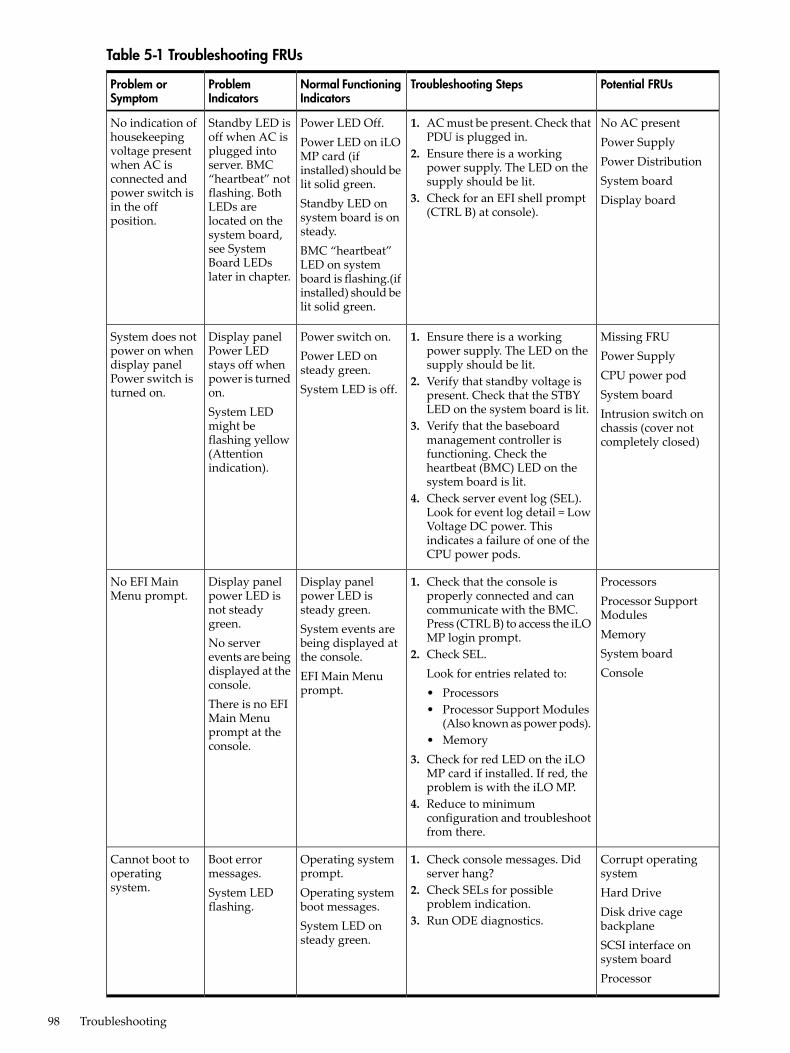
Table 5-1 Troubleshooting FRUs
Potential FRUsTroubleshooting StepsNormal FunctioningIndicators
ProblemIndicators
Problem orSymptom
No AC presentPower SupplyPower DistributionSystem boardDisplay board
1. AC must be present. Check thatPDU is plugged in.
2. Ensure there is a workingpower supply. The LED on thesupply should be lit.
3. Check for an EFI shell prompt(CTRL B) at console).
Power LED Off.Power LED on iLOMP card (ifinstalled) should belit solid green.Standby LED onsystem board is onsteady.BMC “heartbeat”LED on systemboard is flashing.(ifinstalled) should belit solid green.
Standby LED isoff when AC isplugged intoserver. BMC“heartbeat” notflashing. BothLEDs arelocated on thesystem board,see SystemBoard LEDslater in chapter.
No indication ofhousekeepingvoltage presentwhen AC isconnected andpower switch isin the offposition.
Missing FRUPower SupplyCPU power podSystem boardIntrusion switch onchassis (cover notcompletely closed)
1. Ensure there is a workingpower supply. The LED on thesupply should be lit.
2. Verify that standby voltage ispresent. Check that the STBYLED on the system board is lit.
3. Verify that the baseboardmanagement controller isfunctioning. Check theheartbeat (BMC) LED on thesystem board is lit.
4. Check server event log (SEL).Look for event log detail = LowVoltage DC power. Thisindicates a failure of one of theCPU power pods.
Power switch on.Power LED onsteady green.System LED is off.
Display panelPower LEDstays off whenpower is turnedon.System LEDmight beflashing yellow(Attentionindication).
System does notpower on whendisplay panelPower switch isturned on.
ProcessorsProcessor SupportModulesMemorySystem boardConsole
1. Check that the console isproperly connected and cancommunicate with the BMC.Press (CTRL B) to access the iLOMP login prompt.
2. Check SEL.Look for entries related to:• Processors• Processor Support Modules
(Also known as power pods).• Memory
3. Check for red LED on the iLOMP card if installed. If red, theproblem is with the iLO MP.
4. Reduce to minimumconfiguration and troubleshootfrom there.
Display panelpower LED issteady green.System events arebeing displayed atthe console.EFI Main Menuprompt.
Display panelpower LED isnot steadygreen.No serverevents are beingdisplayed at theconsole.There is no EFIMain Menuprompt at theconsole.
No EFI MainMenu prompt.
Corrupt operatingsystemHard DriveDisk drive cagebackplaneSCSI interface onsystem boardProcessor
1. Check console messages. Didserver hang?
2. Check SELs for possibleproblem indication.
3. Run ODE diagnostics.
Operating systemprompt.Operating systemboot messages.System LED onsteady green.
Boot errormessages.System LEDflashing.
Cannot boot tooperatingsystem.
98 Troubleshooting

Verifying Hard Drive OperationEach hard drive has an activity LED indicator on the front of the drive. See Figure 5-1.
NOTE: Only the Activity LED is used. The Status LED is not monitored by HP-UX.
Figure 5-1 LED Apertures on Hard Drive
Lightpipes on the disk drive transmit light to these apertures from LEDs on the inside rear ofthe hot-swap mass storage cage. Verify that the LED shows the correct activity indication for alldisk drives that you installed:1. Turn on power to the server and display monitor.2. During the boot sequence, watch the Activity LED on each hard drive. The LED quickly
cycles from amber to green. The LED stays steady green until the drive spins up.3. If the activity LED is illuminated on any disk drive, the drive cage might not be correctly
installed. Check installation as follows:a. Power off the server using the power switch and unplug the AC power cords and any
cables.b. Disconnect the power distribution cable between the drive cage and the power
distribution module and then reconnect it.c. Verify that the SCSI interface is correctly installed from SCSI A channel connector on
the system board to the connector on the SCSI cage.d. Ensure that the SCSI bus is loaded properly.e. Reconnect the AC power cords and any cables. Restart the server to determine whether
the LEDs now become illuminated during the boot. If not, contact your reseller.4. If the LED indicator on a single disk drive is not illuminated during boot, the disk drive
might be installed incorrectly, or its lightpipes might be damaged.Check the lightpipe on the disk drive as follows:a. Remove the disk drive.b. Inspect the lightpipes for damage. If a lightpipe is damaged, contact your reseller.
CAUTION: The lightpipes are fragile. Be careful not to damage them when you inspectthem or when you reinsert the disk drive.
c. Reinstall the disk drive.d. Restart the server to determine whether the LED now becomes illuminated during the
boot. If not, contact your reseller.
5. Use the EFI shell command info io to check the SCSI drives.
Verifying Hard Drive Operation 99
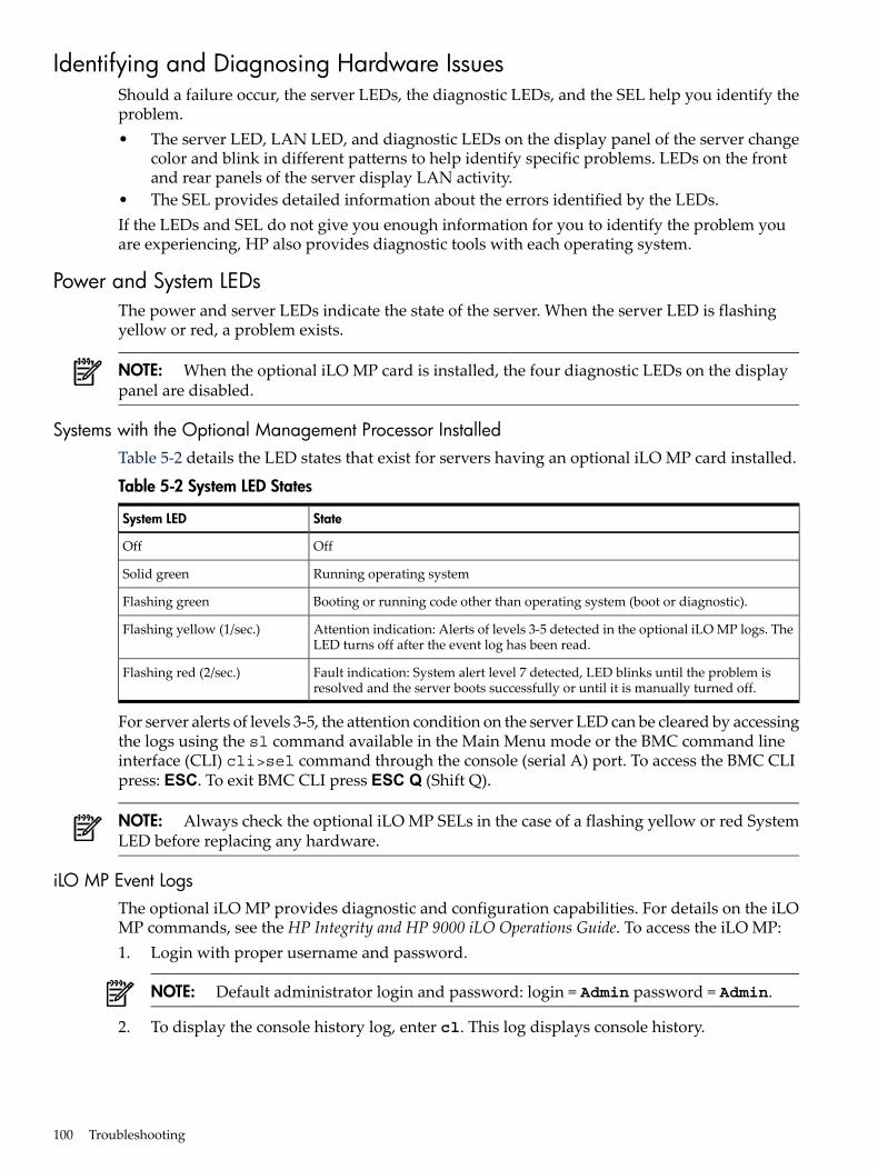
Identifying and Diagnosing Hardware IssuesShould a failure occur, the server LEDs, the diagnostic LEDs, and the SEL help you identify theproblem.• The server LED, LAN LED, and diagnostic LEDs on the display panel of the server change
color and blink in different patterns to help identify specific problems. LEDs on the frontand rear panels of the server display LAN activity.
• The SEL provides detailed information about the errors identified by the LEDs.If the LEDs and SEL do not give you enough information for you to identify the problem youare experiencing, HP also provides diagnostic tools with each operating system.
Power and System LEDsThe power and server LEDs indicate the state of the server. When the server LED is flashingyellow or red, a problem exists.
NOTE: When the optional iLO MP card is installed, the four diagnostic LEDs on the displaypanel are disabled.
Systems with the Optional Management Processor InstalledTable 5-2 details the LED states that exist for servers having an optional iLO MP card installed.
Table 5-2 System LED States
StateSystem LED
OffOff
Running operating systemSolid green
Booting or running code other than operating system (boot or diagnostic).Flashing green
Attention indication: Alerts of levels 3-5 detected in the optional iLO MP logs. TheLED turns off after the event log has been read.
Flashing yellow (1/sec.)
Fault indication: System alert level 7 detected, LED blinks until the problem isresolved and the server boots successfully or until it is manually turned off.
Flashing red (2/sec.)
For server alerts of levels 3-5, the attention condition on the server LED can be cleared by accessingthe logs using the sl command available in the Main Menu mode or the BMC command lineinterface (CLI) cli>sel command through the console (serial A) port. To access the BMC CLIpress: ESC. To exit BMC CLI press ESC Q (Shift Q).
NOTE: Always check the optional iLO MP SELs in the case of a flashing yellow or red SystemLED before replacing any hardware.
iLO MP Event LogsThe optional iLO MP provides diagnostic and configuration capabilities. For details on the iLOMP commands, see the HP Integrity and HP 9000 iLO Operations Guide. To access the iLO MP:1. Login with proper username and password.
NOTE: Default administrator login and password: login = Admin password = Admin.
2. To display the console history log, enter cl. This log displays console history.
100 Troubleshooting
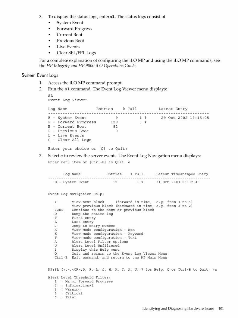
3. To display the status logs, entersl. The status logs consist of:• System Event• Forward Progress• Current Boot• Previous Boot• Live Events• Clear SEL/FPL Logs
For a complete explanation of configuring the iLO MP and using the iLO MP commands, seethe HP Integrity and HP 9000 iLO Operations Guide.
System Event Logs1. Access the iLO MP command prompt.2. Run the sl command. The Event Log Viewer menu displays:
SLEvent Log Viewer:
Log Name Entries % Full Latest Entry-------------------------------------------------------------------E - System Event 9 1 % 29 Oct 2002 19:15:05F - Forward Progress 129 3 %B - Current Boot 82P - Previous Boot 0L - Live EventsC - Clear All Logs
Enter your choice or [Q] to Quit:
3. Select e to review the server events. The Event Log Navigation menu displays:Enter menu item or [Ctrl-B] to Quit: e
Log Name Entries % Full Latest Timestamped Entry--------------------------------------------------------------------------- E - System Event 12 1 % 31 Oct 2003 23:37:45
Event Log Navigation Help:
+ View next block (forward in time, e.g. from 3 to 4) - View previous block (backward in time, e.g. from 3 to 2) <CR> Continue to the next or previous block D Dump the entire log F First entry L Last entry J Jump to entry number H View mode configuration - Hex K View mode configuration - Keyword T View mode configuration - Text A Alert Level Filter options U Alert Level Unfiltered ? Display this Help menu Q Quit and return to the Event Log Viewer Menu Ctrl-B Exit command, and return to the MP Main Menu
MP:SL (+,-,<CR>,D, F, L, J, H, K, T, A, U, ? for Help, Q or Ctrl-B to Quit) >a
Alert Level Threshold Filter: 1 : Major Forward Progress 2 : Informational 3 : Warning 5 : Critical 7 : Fatal
Identifying and Diagnosing Hardware Issues 101

Enter alert level threshold or [Q] to quit filter setup: 3
-> Alert threshold level 3 filter will be applied.
Set up alert filter options on this buffer? (Y/[N])
Log Name Entries % Full Latest Entry-------------------------------------------------------------------E - System Event 410 47 % 18 Feb 2003 09:38:10
Event Log Navigation Help:
+ View next block (forward in time, e.g. from 3 to 4) - View previous block (backward in time, e.g. from 3 to 2) <CR> Continue to the next or previous block D Dump the entire log for capture and analysis F First entry L Last entry J Jump to entry number V View mode configuration (text, keyword, hex) ? Display this Help menu Ctrl-B Quit and return to the Main Menu
4. Select a, and a threshold filter number to filter events to the desired level.MP:SL (+,-,<CR>,D, F, L, J, H, K, T, A, U, ? for Help, Q or Ctrl-B to Quit) >a
Alert Level Threshold Filter: 1 : Major Forward Progress 2 : Informational 3 : Warning 5 : Critical 7 : Fatal
Enter alert level threshold or [Q] to quit filter setup: 3
-> Alert threshold level 3 filter will be applied.
5. Select t to change the display to text mode:Display Mode Configuration: H - Hex mode Current -> K - Keyword mode T - Text modeEnter new value, or [Q] to Quit:
102 Troubleshooting
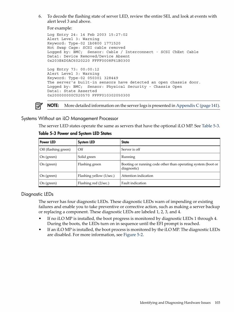
6. To decode the flashing state of server LED, review the entire SEL and look at events withalert level 3 and above.For example:Log Entry 24: 14 Feb 2003 15:27:02Alert Level 3: WarningKeyword: Type-02 1b0800 1771520Hot Swap Cage: SCSI cable removedLogged by: BMC; Sensor: Cable / Interconnect - SCSI ChExt CableData1: Device Removed/Device Absent0x203E4D0AC6020220 FFFF0008F61B0300
Log Entry 73: 00:00:12Alert Level 3: WarningKeyword: Type-02 050301 328449The server's built-in sensors have detected an open chassis door.Logged by: BMC; Sensor: Physical Security - Chassis OpenData1: State Asserted0x200000000C020570 FFFF010302050300
NOTE: More detailed information on the server logs is presented in Appendix C (page 141).
Systems Without an iLO Management ProcessorThe server LED states operate the same as servers that have the optional iLO MP. See Table 5-3.
Table 5-3 Power and System LED States
StateSystem LEDPower LED
Server is offOffOff (flashing green)
RunningSolid greenOn (green)
Booting or running code other than operating system (boot ordiagnostic)
Flashing greenOn (green)
Attention indicationFlashing yellow (1/sec.)On (green)
Fault indicationFlashing red (2/sec.)On (green)
Diagnostic LEDsThe server has four diagnostic LEDs. These diagnostic LEDs warn of impending or existingfailures and enable you to take preventive or corrective action, such as making a server backupor replacing a component. These diagnostic LEDs are labeled 1, 2, 3, and 4.• If no iLO MP is installed, the boot progress is monitored by diagnostic LEDs 1 through 4.
During the boots, the LEDs turn on in sequence until the EFI prompt is reached.• If an iLO MP is installed, the boot process is monitored by the iLO MP. The diagnostic LEDs
are disabled. For more information, see Figure 5-2.
Identifying and Diagnosing Hardware Issues 103
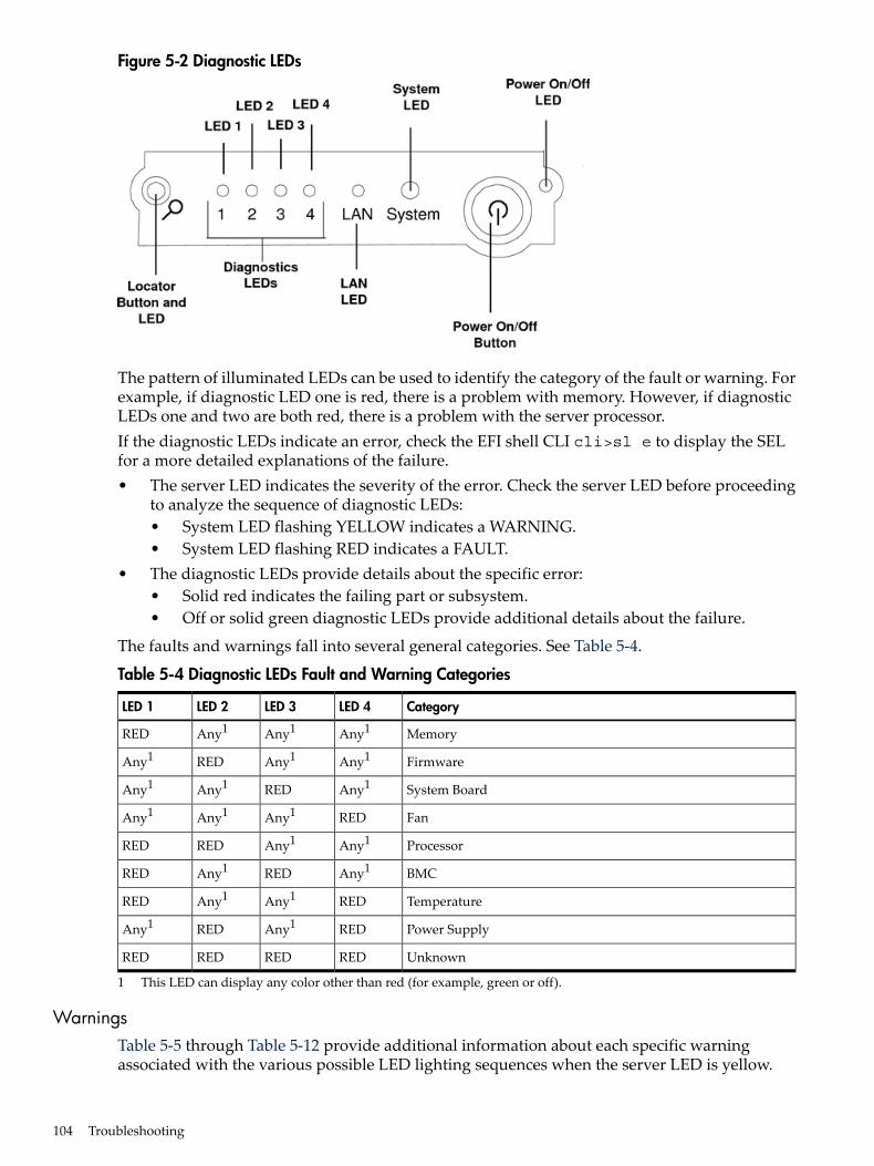
Figure 5-2 Diagnostic LEDs
The pattern of illuminated LEDs can be used to identify the category of the fault or warning. Forexample, if diagnostic LED one is red, there is a problem with memory. However, if diagnosticLEDs one and two are both red, there is a problem with the server processor.If the diagnostic LEDs indicate an error, check the EFI shell CLI cli>sl e to display the SELfor a more detailed explanations of the failure.• The server LED indicates the severity of the error. Check the server LED before proceeding
to analyze the sequence of diagnostic LEDs:• System LED flashing YELLOW indicates a WARNING.• System LED flashing RED indicates a FAULT.
• The diagnostic LEDs provide details about the specific error:• Solid red indicates the failing part or subsystem.• Off or solid green diagnostic LEDs provide additional details about the failure.
The faults and warnings fall into several general categories. See Table 5-4.
Table 5-4 Diagnostic LEDs Fault and Warning Categories
CategoryLED 4LED 3LED 2LED 1
MemoryAny1Any1Any1RED
FirmwareAny1Any1REDAny1
System BoardAny1REDAny1Any1
FanREDAny1Any1Any1
ProcessorAny1Any1REDRED
BMCAny1REDAny1RED
TemperatureREDAny1Any1RED
Power SupplyREDAny1REDAny1
UnknownREDREDREDRED
1 This LED can display any color other than red (for example, green or off).
WarningsTable 5-5 through Table 5-12 provide additional information about each specific warningassociated with the various possible LED lighting sequences when the server LED is yellow.
104 Troubleshooting
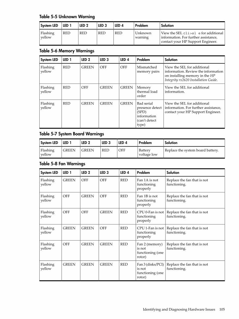
Table 5-5 Unknown Warning
SolutionProblemLED 4LED 3LED 2LED 1System LED
View the SEL cli>sl e for additionalinformation. For further assistance,contact your HP Support Engineer.
Unknownwarning
REDREDREDREDFlashingyellow
Table 5-6 Memory Warnings
SolutionProblemLED 4LED 3LED 2LED 1System LED
View the SEL for additionalinformation. Review the informationon installing memory in the HPIntegrity rx2620 Installation Guide.
Mismatchedmemory pairs
OFFOFFGREENREDFlashingyellow
View the SEL for additionalinformation.
Memorythermal loadorder
GREENGREENOFFREDFlashingyellow
View the SEL for additionalinformation. For further assistance,contact your HP Support Engineer.
Bad serialpresence detect(SPD)information(can't detecttype)
GREENGREENGREENREDFlashingyellow
Table 5-7 System Board Warnings
SolutionProblemLED 4LED 3LED 2LED 1System LED
Replace the system board battery.Batteryvoltage low
OFFREDGREENGREENFlashingyellow
Table 5-8 Fan Warnings
SolutionProblemLED 4LED 3LED 2LED 1System LED
Replace the fan that is notfunctioning.
Fan 1A is notfunctioningproperly
REDOFFOFFGREENFlashingyellow
Replace the fan that is notfunctioning.
Fan 1B is notfunctioningproperly
REDOFFGREENOFFFlashingyellow
Replace the fan that is notfunctioning.
CPU 0-Fan is notfunctioningproperly
REDGREENOFFOFFFlashingyellow
Replace the fan that is notfunctioning.
CPU 1-Fan is notfunctioningproperly
REDOFFGREENGREENFlashingyellow
Replace the fan that is notfunctioning.
Fan 2 (memory)is notfunctioning (onerotor)
REDGREENGREENOFFFlashingyellow
Replace the fan that is notfunctioning.
Fan 3 (disks/PCI)is notfunctioning (onerotor)
REDGREENGREENGREENFlashingyellow
Identifying and Diagnosing Hardware Issues 105

Table 5-9 Processor Warnings
SolutionProblemLED 4LED 3LED 2LED 1System LED
Make sure nothing is blocking theserver airflow and locate your server inan air-conditioned room.
Processor 0temperatureexceeds limit
OFFGREENREDREDFlashingyellow
Make sure nothing is blocking theserver airflow and locate your server inan air-conditioned room.
Processor 1temperatureexceeds limit
GREENOFFREDREDFlashingyellow
Table 5-10 Temperature Warnings
SolutionProblemLED 4LED 3LED 2LED 1System LED
Make sure nothing is blocking theserver airflow and locate your serverin an air-conditioned room.
External airtemperaturetoo high
REDGREENGREENREDFlashingyellow
Table 5-11 Video Warnings
SolutionProblemLED 4LED 3LED 2LED 1System LED
Install a video adapter. See theinstallation instructions that shippedwith the video adapter.
No videoadapterpresent
OFFREDREDOFFFlashingyellow
Table 5-12 Power Supply Warnings
SolutionProblemLED 4LED 3LED 2LED 1System LED
Check the power supply LED. Replacethe power supply.
Power supplyfault
REDOFFREDGREENFlashingyellow
FaultsTable 5-13 through Table 5-21 provide additional information about each specific fault associatedwith the various possible LED lighting sequences when the server LED is red.
Table 5-13 Unknown Faults
SolutionProblemLED 4LED 3LED 2LED 1System LED
View the SEL for additionalinformation. For further assistance,contact your HP Support Engineer.
Unknownfault
REDREDREDREDFlashingRed
Table 5-14 Memory Faults
SolutionProblemLED 4LED 3LED 2LED 1System LED
Review the information on installingmemory in the HP Integrity rx2620Installation Guide.
Mismatchedmemory pairs
OFFOFFGREENREDFlashingRed
Replace memory.Fatal memoryerror
GREENOFFOFFOFFFlashingRed
Install memory.No memoryinstalled
OFFGREENGREENREDFlashingRed
Reseat the DIMMs. If the errorpersists, replace them.
Bad Memory.One or moreDIMMs arebad or notseatedproperly.
GREENGREENGREENREDFlashingRed
106 Troubleshooting
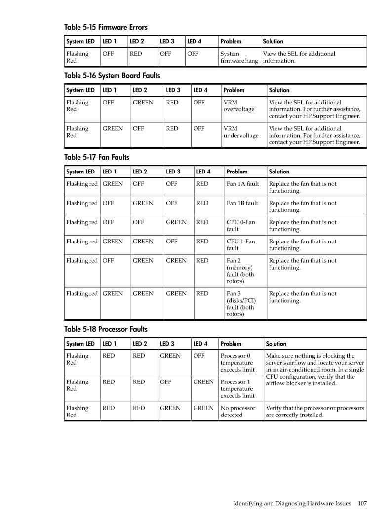
Table 5-15 Firmware Errors
SolutionProblemLED 4LED 3LED 2LED 1System LED
View the SEL for additionalinformation.
Systemfirmware hang
OFFOFFREDOFFFlashingRed
Table 5-16 System Board Faults
SolutionProblemLED 4LED 3LED 2LED 1System LED
View the SEL for additionalinformation. For further assistance,contact your HP Support Engineer.
VRMovervoltage
OFFREDGREENOFFFlashingRed
View the SEL for additionalinformation. For further assistance,contact your HP Support Engineer.
VRMundervoltage
OFFREDOFFGREENFlashingRed
Table 5-17 Fan Faults
SolutionProblemLED 4LED 3LED 2LED 1System LED
Replace the fan that is notfunctioning.
Fan 1A faultREDOFFOFFGREENFlashing red
Replace the fan that is notfunctioning.
Fan 1B faultREDOFFGREENOFFFlashing red
Replace the fan that is notfunctioning.
CPU 0-Fanfault
REDGREENOFFOFFFlashing red
Replace the fan that is notfunctioning.
CPU 1-Fanfault
REDOFFGREENGREENFlashing red
Replace the fan that is notfunctioning.
Fan 2(memory)fault (bothrotors)
REDGREENGREENOFFFlashing red
Replace the fan that is notfunctioning.
Fan 3(disks/PCI)fault (bothrotors)
REDGREENGREENGREENFlashing red
Table 5-18 Processor Faults
SolutionProblemLED 4LED 3LED 2LED 1System LED
Make sure nothing is blocking theserver’s airflow and locate your serverin an air-conditioned room. In a singleCPU configuration, verify that theairflow blocker is installed.
Processor 0temperatureexceeds limit
OFFGREENREDREDFlashingRed
Processor 1temperatureexceeds limit
GREENOFFREDREDFlashingRed
Verify that the processor or processorsare correctly installed.
No processordetected
GREENGREENREDREDFlashingRed
Identifying and Diagnosing Hardware Issues 107

Table 5-19 BMC Faults
SolutionProblemLED 4LED 3LED 2LED 1System LED
Turn off and unplug the server. Wait20 seconds, then plug in and restartthe server. If the error repeats, replacethe base unit.
BMC firmwareis damaged
OFFREDGREENREDFlashingRed
View the SEL for additionalinformation.
System boardFRU inventorydeviceinaccessible
GREENREDGREENREDFlashingRed
Table 5-20 Temperature Faults
SolutionProblemLED 4LED 3LED 2LED 1System LED
Make sure nothing is blocking theserver airflow and locate your serverin an air-conditioned room.
External airtemperature toohigh
REDGREENGREENREDFlashingRed
Table 5-21 Power Supply Errors
SolutionProblemLED 4LED 3LED 2LED 1System LED
View the SEL for additionalinformation.
VRM or power podfault
REDOFFREDOFFFlashingRed
Power Supply 1 faultREDOFFREDGREENFlashingRed
Power Supply 2 faultREDGREENREDOFFFlashingRed
12V out of range(power supplyinterface fault)
REDGREENREDGREENFlashingRed
Command Line InterfaceThe baseboard management controller (BMC) is accessable by means of the BMC consolecommands, or command line interface (CLI). The commands are similar to the iLO MP commandsbut are slightly less interactive.
Command Line Interface MenuThe CLI provides the following menu selections:date: Date displayhelp: List available commandsipmi: Send IPMI cmdloc: System locatorLEDpasswd: Change passwordpc: Power controlpr: Power restore policyps: Power statusrs:System resetsl: Show logssr: Display firmware revisionstc: System resetexit: Exit
Troubleshooting Example Using CLIThis example uses the CLI and the SEL to display error message indicating that no memory isinstalled.cli>sl e# Sev Generator/Sensor Description Event ID Data, Timestamp---- - ---------------- ------------ ----------- --------------------------
00A0 - SFW FW error 00-0F:70:40 3F:-- 2003-10-31 22:29:0600B0 7 CPU0 Mem no DIMMs 000D0 DT 00 000000000000000000C0 7 CPU0 Mem no DIMMs 000D0 Time 2003-10-31 22:29:0600D0 - SFW FW error 00-0F:70:40 3F:-- 2003-10-31 22:29:06
108 Troubleshooting
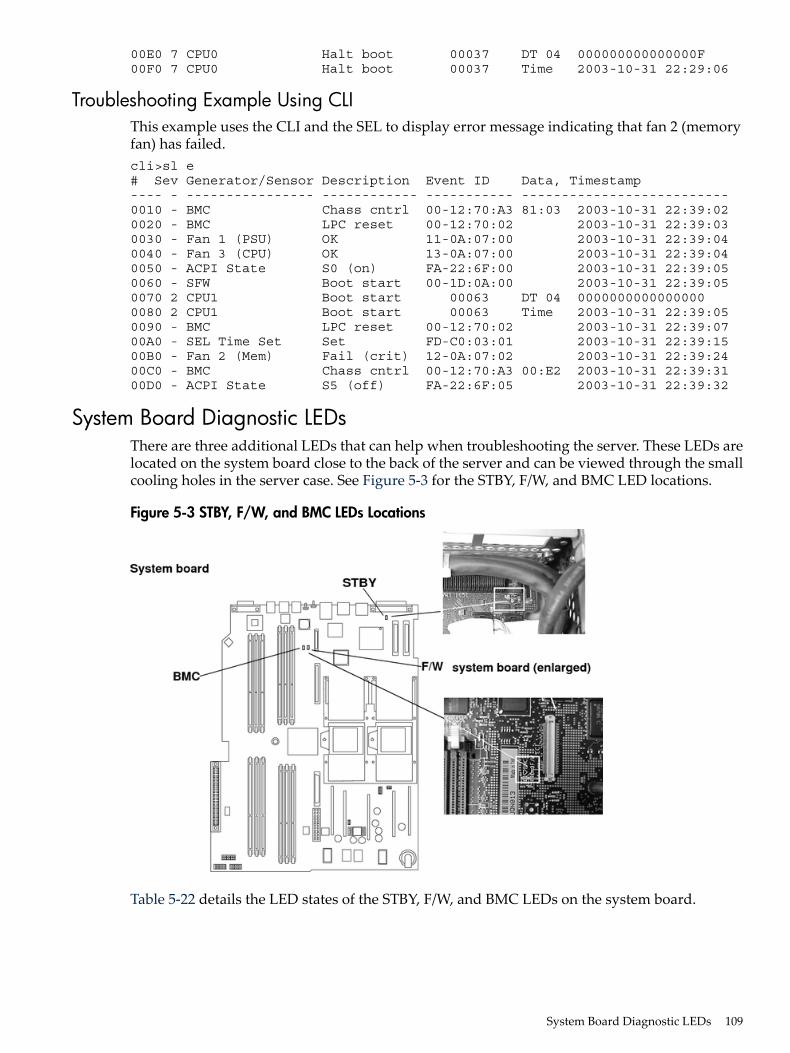
00E0 7 CPU0 Halt boot 00037 DT 04 000000000000000F00F0 7 CPU0 Halt boot 00037 Time 2003-10-31 22:29:06
Troubleshooting Example Using CLIThis example uses the CLI and the SEL to display error message indicating that fan 2 (memoryfan) has failed.cli>sl e# Sev Generator/Sensor Description Event ID Data, Timestamp---- - ---------------- ------------ ----------- --------------------------0010 - BMC Chass cntrl 00-12:70:A3 81:03 2003-10-31 22:39:020020 - BMC LPC reset 00-12:70:02 2003-10-31 22:39:030030 - Fan 1 (PSU) OK 11-0A:07:00 2003-10-31 22:39:040040 - Fan 3 (CPU) OK 13-0A:07:00 2003-10-31 22:39:040050 - ACPI State S0 (on) FA-22:6F:00 2003-10-31 22:39:050060 - SFW Boot start 00-1D:0A:00 2003-10-31 22:39:050070 2 CPU1 Boot start 00063 DT 04 00000000000000000080 2 CPU1 Boot start 00063 Time 2003-10-31 22:39:050090 - BMC LPC reset 00-12:70:02 2003-10-31 22:39:0700A0 - SEL Time Set Set FD-C0:03:01 2003-10-31 22:39:1500B0 - Fan 2 (Mem) Fail (crit) 12-0A:07:02 2003-10-31 22:39:2400C0 - BMC Chass cntrl 00-12:70:A3 00:E2 2003-10-31 22:39:3100D0 - ACPI State S5 (off) FA-22:6F:05 2003-10-31 22:39:32
System Board Diagnostic LEDsThere are three additional LEDs that can help when troubleshooting the server. These LEDs arelocated on the system board close to the back of the server and can be viewed through the smallcooling holes in the server case. See Figure 5-3 for the STBY, F/W, and BMC LED locations.
Figure 5-3 STBY, F/W, and BMC LEDs Locations
Table 5-22 details the LED states of the STBY, F/W, and BMC LEDs on the system board.
System Board Diagnostic LEDs 109

Table 5-22 System Board LEDs
DescriptionLED
This green standby LED comes on as soon as the server power cord is plugged in.STBY (power good)
A few seconds after the server is plugged in this green LED starts flashing indicating the BMCsoftware is operational.
BMC (heartbeat)
A few seconds after the server power is turned on, the server firmware code fetch green LEDcomes on indicating that the firmware has started the boot process.
F/W
LAN LEDsThere are front panel and rear panel LAN LEDs on the server.
Front Panel LAN LEDsThere is a diference in the LED display when the server AC power is on and the system DCpower is off (or in EFI mode).With the LAN cable connected, the front panel LAN LED displays as follows:• LAN LED is off (even if AC power is on)• Solid green, LAN link is established, no current LAN activity
Rear Panel LAN LEDsThere are two 1 Gb LAN ports on the rear panel. They are LAN A and LAN B.
LAN A Connector LEDsThe 1 Gb LAN A interface provides four LEDs on the rear panel. Table 5-23 details the LEDlocations and states for the LAN A connector.
Table 5-23 Gb LAN A Connector LEDs
DescriptionColorLocationLAN LED
NoneNoneTopNot used
Flashing amber: the 1000 Mbps with Ethernet protocol andtwisted-pair wiring is enabled.Off: no link.
AmberSecond from top1000mb
Flashing green: the 100 Mbps with Ethernet protocol andtwisted-pair wiring is enabled.Off: no link.
GreenSecond from bottom100mb
Flashing green: The Activity LED lights, and all other LEDsare off for a 10 Mbps connection.Off: no activity
GreenBottomActivity
LAN B Connector LEDsThe 1Gb LAN B interface provides two LEDs on the rear panel (the LED on the left is not used).Table 5-24 details the LED locations and states for the LAN B connector.
Table 5-24 Gb LAN B Connector LEDs
DescriptionColorLocation
The 1000 MHz with Ethernet protocol and twisted-pair wiring is enabled,off: no link
YellowSpeed (upper left)
The 100 MHz with Ethernet protocol and twisted-pair wiring is enabled,off: no link
GreenSpeed (upper left)
110 Troubleshooting

Table 5-24 Gb LAN B Connector LEDs (continued)
DescriptionColorLocation
LinkGreenLink (upper right)
Off: No linkLink (upper right)
Optional Management Processor LAN LEDsFour iLO MP LAN LEDs are also on the rear panel if the server has an iLO MP installed. Table 5-25details the LED locations and states for the LAN A connector.
Table 5-25 Optional Management Processor LAN LEDs
StateColorLocationLAN LED
Management processor running selftest or error
YellowTopSelf-test
Management processor has bootedOff
10BT link establishedGreenSecond from top10BT
10BT activityFlashing green
No link or 100BT linkOff
100BT link establishedGreenSecond from bottom100BT
100BT activityFlashing green
No link or 10BT linkOff
Standby power onGreenBottomStandbyPower
Standby power offOff
DiagnosticsA suite of offline and online support tools are available to enable you to troubleshoot serverproblems. In general, if the operating system (HP-UX) is running, do not shut it down. Use theonline support tools.If the operating system cannot be booted, use the offline support tools to resolve the problem.The offline support tools are available from the EFI partition. After you resolve the problem,boot HP-UX, and use the online support tools for any further testing.You cannot reach the EFI from either the main disk or from LAN, you must troubleshoot usingthe visual fault indicators, console messages, and system error logs that are available.
Online Diagnostics and ExercisersOnline support tools are provided under both operating systems. Centralized error archivingand hardware inventory tools are available as long as the agents/providers that support themare installed on the managed server.On HP-UX systems, the legacy tools within OnlineDiag continue to be supported. The onlinesupport tools, on HP-UX 11.23 and greater, include the Support Tool Manager (STM) tools andthe additional Web-Based Enterprise Management (WBEM) features added by SysFaultMgmt.The STM tools include verifiers, diagnostics, exercisers, information modules, and expert tools.Verifiers quickly determine whether or not a specific device is operational by performing taskssimilar in nature to the way applications use the device. No license is required to run the verifiers.Diagnostics are tools designed to identify faulty or failed FRUs.
Diagnostics 111
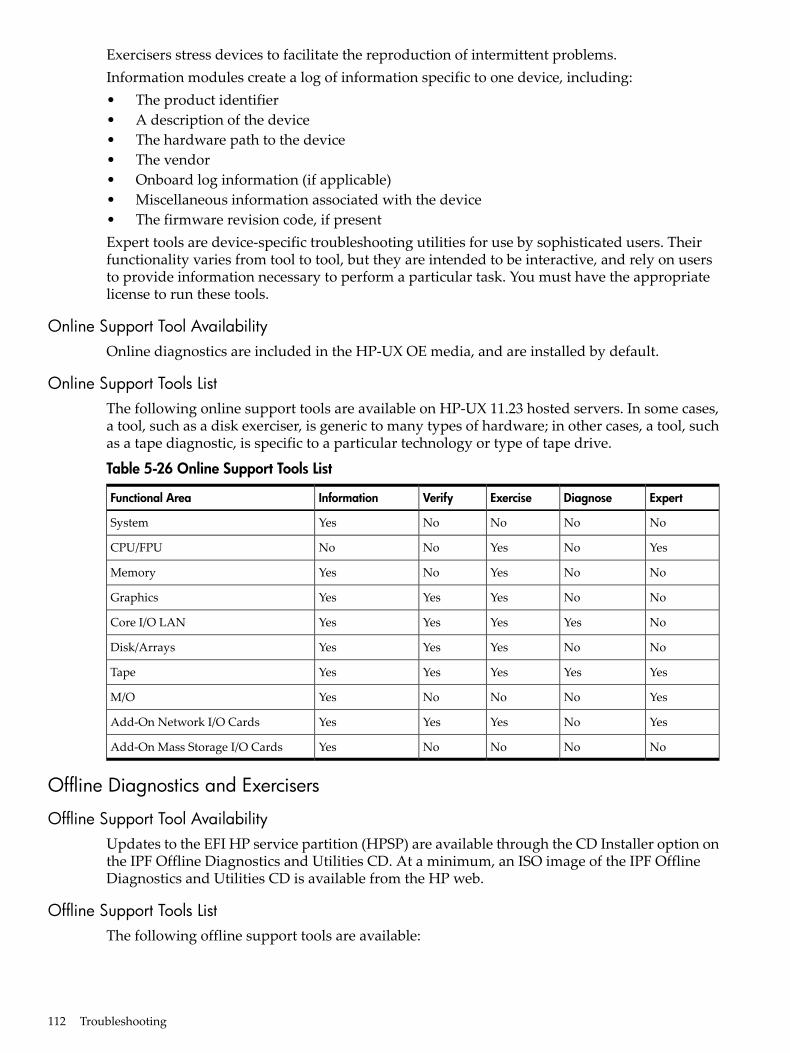
Exercisers stress devices to facilitate the reproduction of intermittent problems.Information modules create a log of information specific to one device, including:• The product identifier• A description of the device• The hardware path to the device• The vendor• Onboard log information (if applicable)• Miscellaneous information associated with the device• The firmware revision code, if presentExpert tools are device-specific troubleshooting utilities for use by sophisticated users. Theirfunctionality varies from tool to tool, but they are intended to be interactive, and rely on usersto provide information necessary to perform a particular task. You must have the appropriatelicense to run these tools.
Online Support Tool AvailabilityOnline diagnostics are included in the HP-UX OE media, and are installed by default.
Online Support Tools ListThe following online support tools are available on HP-UX 11.23 hosted servers. In some cases,a tool, such as a disk exerciser, is generic to many types of hardware; in other cases, a tool, suchas a tape diagnostic, is specific to a particular technology or type of tape drive.
Table 5-26 Online Support Tools List
ExpertDiagnoseExerciseVerifyInformationFunctional Area
NoNoNoNoYesSystem
YesNoYesNoNoCPU/FPU
NoNoYesNoYesMemory
NoNoYesYesYesGraphics
NoYesYesYesYesCore I/O LAN
NoNoYesYesYesDisk/Arrays
YesYesYesYesYesTape
YesNoNoNoYesM/O
YesNoYesYesYesAdd-On Network I/O Cards
NoNoNoNoYesAdd-On Mass Storage I/O Cards
Offline Diagnostics and Exercisers
Offline Support Tool AvailabilityUpdates to the EFI HP service partition (HPSP) are available through the CD Installer option onthe IPF Offline Diagnostics and Utilities CD. At a minimum, an ISO image of the IPF OfflineDiagnostics and Utilities CD is available from the HP web.
Offline Support Tools ListThe following offline support tools are available:
112 Troubleshooting
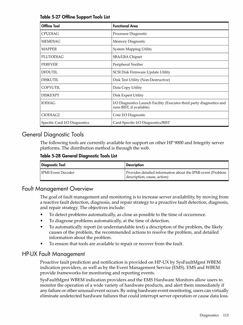
Table 5-27 Offline Support Tools List
Functional AreaOffline Tool
Processor DiagnosticCPUDIAG
Memory DiagnosticMEMDIAG
System Mapping UtilityMAPPER
SBA/LBA ChipsetPLUTODIAG
Peripheral VerifierPERFVER
SCSI Disk Firmware Update UtilityDFDUTIL
Disk Test Utility (Non-Destructive)DISKUTIL
Data Copy UtilityCOPYUTIL
Disk Expert UtilityDISKEXPT
I/O Diagnostics Launch Facility (Executes third party diagnostics andruns BIST, if available)
IODIAG
Core I/O DiagnosticCIODIAG2
Card-Specific I/O Diagnostics/BISTSpecific Card I/O Diagnostics
General Diagnostic ToolsThe following tools are currently available for support on other HP 9000 and Integrity serverplatforms. The distribution method is through the web.
Table 5-28 General Diagnostic Tools List
DescriptionDiagnostic Tool
Provides detailed information about the IPMI event (Problemdescription, cause, action)
IPMI Event Decoder
Fault Management OverviewThe goal of fault management and monitoring is to increase server availability, by moving froma reactive fault detection, diagnosis, and repair strategy to a proactive fault detection, diagnosis,and repair strategy. The objectives include:• To detect problems automatically, as close as possible to the time of occurrence.• To diagnose problems automatically, at the time of detection.• To automatically report (in understandable text) a description of the problem, the likely
causes of the problem, the recommended actions to resolve the problem, and detailedinformation about the problem.
• To ensure that tools are available to repair or recover from the fault.
HP-UX Fault ManagementProactive fault prediction and notification is provided on HP-UX by SysFaultMgmt WBEMindication providers, as well as by the Event Management Service (EMS). EMS and WBEMprovide frameworks for monitoring and reporting events.SysFaultMgmt WBEM indication providers and the EMS Hardware Monitors allow users tomonitor the operation of a wide variety of hardware products, and alert them immediately ifany failure or other unusual event occurs. By using hardware event monitoring, users can virtuallyeliminate undetected hardware failures that could interrupt server operation or cause data loss.
Diagnostics 113
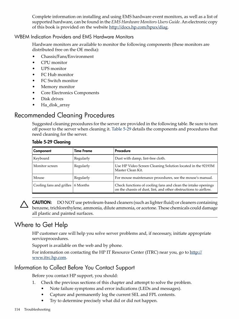
Complete information on installing and using EMS hardware event monitors, as well as a list ofsupported hardware, can be found in the EMSHardwareMonitors Users Guide. An electronic copyof this book is provided on the website http://docs.hp.com/hpux/diag.
WBEM Indication Providers and EMS Hardware MonitorsHardware monitors are available to monitor the following components (these monitors aredistributed free on the OE media):• Chassis/Fans/Environment• CPU monitor• UPS monitor• FC Hub monitor• FC Switch monitor• Memory monitor• Core Electronics Components• Disk drives• Ha_disk_array
Recommended Cleaning ProceduresSuggested cleaning procedures for the server are provided in the following table. Be sure to turnoff power to the server when cleaning it. Table 5-29 details the components and procedures thatneed cleaning for the server.
Table 5-29 Cleaning
ProcedureTime FrameComponent
Dust with damp, lint-free cloth.RegularlyKeyboard
Use HP Video Screen Cleaning Solution located in the 92193MMaster Clean Kit.
RegularlyMonitor screen
For mouse maintenance procedures, see the mouse's manual.RegularlyMouse
Check functions of cooling fans and clean the intake openingson the chassis of dust, lint, and other obstructions to airflow.
6 MonthsCooling fans and grilles
CAUTION: DO NOT use petroleum-based cleaners (such as lighter fluid) or cleaners containingbenzene, trichlorethylene, ammonia, dilute ammonia, or acetone. These chemicals could damageall plastic and painted surfaces.
Where to Get HelpHP customer care will help you solve server problems and, if necessary, initiate appropriateserviceprocedures.Support is available on the web and by phone.For information on contacting the HP IT Resource Center (ITRC) near you, go to http://www.itrc.hp.com.
Information to Collect Before You Contact SupportBefore you contact HP support, you should:1. Check the previous sections of this chapter and attempt to solve the problem.
• Note failure symptoms and error indications (LEDs and messages).• Capture and permanently log the current SEL and FPL contents.• Try to determine precisely what did or did not happen.
114 Troubleshooting
2. Collect the following information:• The model number of your server (for example rx2620).• The product number of your server. This can be found on the identification label, which
is found on the pull-out label at the front of the server.• The serial number of your server. This can be found on the identification label.
3. Be familiar with your server configuration.• Are you using the LAN, RS-232, or web interface to monitor the server?• How many processors, DIMMs, and PCI cards have been installed?• What versions of processor, memory, and PCI cards are used and where are they
installed?• What accessories are installed?
4. Determine the following• Which firmware versions are in use?• When did the problem start?• Have recent changes been made to the server?• Which operating system and version is in use?
Online SupportTo contact HP Customer Support online, refer to the Worldwide Limited Warranty and TechnicalSupportGuide or visit us at http://www.hp.com/go/bizsupport. On our web page, enter the servermodel number (rx2620) and search the field.The following information is available on this website:• Software and firmware updates• The latest drivers and utilities• Additional documentation
Phone SupportTo contact HP customer support by phone, locate the HP IT Resource Center (ITRC) near you,at:http://www.itrc.hp.com. Local phone numbers are listed in your native language for help.
Where to Get Help 115

116

A Parts InformationThis appendix provides server part information such as:• Description• Manufacturing part number• Replacement part number• Exchange part number
Field Replaceable Parts ViewThe items in this list and the corresponding item numbers are the field replaceable units (FRUs)for the server. See Figure A-1 for an exploded view of the server.
Figure A-1 Parts Identification
Figure A-2 shows the parts used for a tower-mounted server.
Field Replaceable Parts View 117
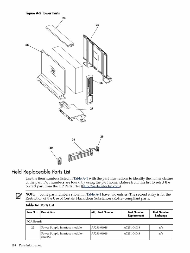
Figure A-2 Tower Parts
Field Replaceable Parts ListUse the item numbers listed in Table A-1 with the part illustrations to identify the nomenclatureof the part. Part numbers are found by using the part nomenclature from this list to select thecorrect part from the HP Partsurfer (http://partsurfer.hp.com).
NOTE: Some part numbers shown in Table A-1 have two entries. The second entry is for theRestriction of the Use of Certain Hazardous Substances (RoHS) compliant parts.
Table A-1 Parts List
Part NumberExchange
Part NumberReplacement
Mfg. Part NumberDescriptionItem No.
PCA Boards
n/aA7231-04018A7231-04018Power Supply Interface module22
n/aA7231-04048A7231-04048Power Supply Interface module -(RoHS)
118 Parts Information
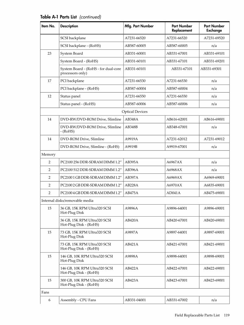
Table A-1 Parts List (continued)
Part NumberExchange
Part NumberReplacement
Mfg. Part NumberDescriptionItem No.
A7231-69520A7231-66520A7231-66520SCSI backplane
n/aAB587-60005AB587-60005SCSI backplane - (RoHS)
AB331-69101AB331-67001AB331-60001System Board23
AB331-69201AB331-67101AB331-60101System Board - (RoHS)
AB331-69301AB331-67101AB331-60101System Board - (RoHS - for dual-coreprocessors only)
n/aA7231-66530A7231-66530PCI backplane17
n/aAB587-60004AB587-60004PCI backplane - (RoHS)
n/aA7231-66550A7231-66550Status panel12
n/aAB587-60006AB587-60006Status panel - (RoHS)
Optical Devices
AB616-69001AB616-62001AB348ADVD-RW/DVD-ROM Drive, Slimline14
n/aAB348-67001AB348BDVD-RW/DVD-ROM Drive, Slimline- (RoHS)
A7231-69012A7231-62012A9919ADVD-ROM Drive, Slimline14
n/aA9919-67001A9919BDVD-ROM Drive, Slimline - (RoHS)
Memory
n/aA6967AXAB395APC2100 256 DDR-SDRAM DIMM 1.2”2
n/aA6968AXAB396APC2100 512 DDR-SDRAM DIMM 1.2”2
A6969-69001A6969AXAB397APC2100 1 GB DDR-SDRAM DIMM 1.2”2
A6835-69001A6970AXAB228APC2100 2 GB DDR-SDRAM DIMM 1.2”2
AB475-69001AD041AAB475APC2100 4 GB DDR-SDRAM DIMM 1.2”2
Internal disks/removable media
A9896-69001A9896-64001A9896A36 GB, 15K RPM Ultra320 SCSIHot-Plug Disk
15
AB420-69001AB420-67001AB420A36 GB, 15K RPM Ultra320 SCSIHot-Plug Disk - (RoHS)
A9897-69001A9897-64001A9897A73 GB, 15K RPM Ultra320 SCSIHot-Plug Disk
15
AB421-69001AB421-67001AB421A73 GB, 15K RPM Ultra320 SCSIHot-Plug Disk - (RoHS)
A9898-69001A9898-64001A9898A146 GB, 10K RPM Ultra320 SCSIHot-Plug Disk
15
AB422-69001AB422-67001AB422A146 GB, 10K RPM Ultra320 SCSIHot-Plug Disk - (RoHS)
AB423-69001AB423-67001AB423A300 GB, 10K RPM Ultra320 SCSIHot-Plug Disk - (RoHS)
15
Fans
n/aAB331-67002AB331-04001Assembly - CPU Fans6
Field Replaceable Parts List 119
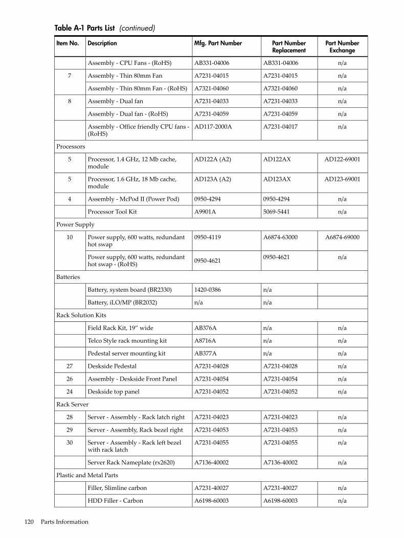
Table A-1 Parts List (continued)
Part NumberExchange
Part NumberReplacement
Mfg. Part NumberDescriptionItem No.
n/aAB331-04006AB331-04006Assembly - CPU Fans - (RoHS)
n/aA7231-04015A7231-04015Assembly - Thin 80mm Fan7
n/aA7321-04060A7321-04060Assembly - Thin 80mm Fan - (RoHS)
n/aA7231-04033A7231-04033Assembly - Dual fan8
n/aA7231-04059A7231-04059Assembly - Dual fan - (RoHS)
n/aA7231-04017AD117-2000AAssembly - Office friendly CPU fans -(RoHS)
Processors
AD122-69001AD122AXAD122A (A2)Processor, 1.4 GHz, 12 Mb cache,module
5
AD123-69001AD123AXAD123A (A2)Processor, 1.6 GHz, 18 Mb cache,module
5
n/a0950-42940950-4294Assembly - McPod II (Power Pod)4
n/a5069-5441A9901AProcessor Tool Kit
Power Supply
A6874-69000A6874-630000950-4119Power supply, 600 watts, redundanthot swap
10
n/a0950-46210950-4621Power supply, 600 watts, redundanthot swap - (RoHS)
Batteries
n/a1420-0386Battery, system board (BR2330)
n/an/aBattery, iLO/MP (BR2032)
Rack Solution Kits
n/an/aAB376AField Rack Kit, 19” wide
n/an/aA8716ATelco Style rack mounting kit
n/an/aAB377APedestal server mounting kit
n/aA7231-04028A7231-04028Deskside Pedestal27
n/aA7231-04054A7231-04054Assembly - Deskside Front Panel26
n/aA7231-04052A7231-04052Deskside top panel24
Rack Server
n/aA7231-04023A7231-04023Server - Assembly - Rack latch right28
n/aA7231-04053A7231-04053Server - Assembly, Rack bezel right29
n/aA7231-04055A7231-04055Server - Assembly - Rack left bezelwith rack latch
30
n/aA7136-40002A7136-40002Server Rack Nameplate (rx2620)
Plastic and Metal Parts
n/aA7231-40027A7231-40027Filler, Slimline carbon
n/aA6198-60003A6198-60003HDD Filler - Carbon
120 Parts Information
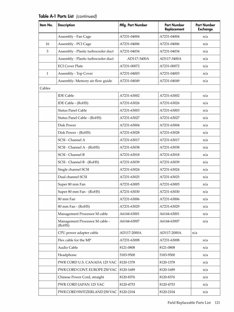
Table A-1 Parts List (continued)
Part NumberExchange
Part NumberReplacement
Mfg. Part NumberDescriptionItem No.
n/aA7231-04004A7231-04004Assembly - Fan Cage
n/aA7231-04006A7231-04006Assembly - PCI Cage16
n/aA7231-04034A7231-04034Assembly - Plastic turbocooler duct3
n/aAD117-3400AAD117-3400AAssembly - Plastic turbocooler duct
n/aA7231-00072A7231-00072ECI Cover Plate
n/aA7231-04003A7231-04003Assembly - Top Cover1
n/aA7231-04049A7231-04049Assembly- Memory air flow guide
Cables
n/aA7231-63002A7231-63002IDE Cable
n/aA7231-63026A7231-63026IDE Cable - (RoHS)
n/aA7231-63003A7231-63003Status Panel Cable
n/aA7231-63027A7231-63027Status Panel Cable - (RoHS)
n/aA7231-63004A7231-63004Disk Power
n/aA7231-63028A7231-63028Disk Power - (RoHS)
n/aA7231-63017A7231-63017SCSI - Channel A
n/aA7231-63038A7231-63038SCSI - Channel A - (RoHS)
n/aA7231-63018A7231-63018SCSI - Channel B
n/aA7231-63039A7231-63039SCSI - Channel B - (RoHS)
n/aA7231-63024A7231-63024Single channel SCSI
n/aA7231-63025A7231-63025Dual channel SCSI
n/aA7231-63005A7231-63005Super 80 mm Fan
n/aA7231-63030A7231-63030Super 80 mm Fan - (RoHS)
n/aA7231-63006A7231-6300680 mm Fan
n/aA7231-63029A7231-6302980 mm Fan - (RoHS)
n/aA6144-63001A6144-63001Management Processor M cable
n/aA6144-63007A6144-63007Management Processor M cable -(RoHS)
n/aAD117-2000AAD117-2000ACPU power adapter cable
n/aA7231-63008A7231-63008Flex cable for the MP
n/a8121-08088121-0808Audio Cable
n/a5183-95005183-9500Headphone
n/a8120-13788120-1378PWR CORD U.S. CANADA 125 VAC
n/a8120-16898120-1689PWR CORD CONT. EUROPE 250 VAC
n/a8120-83768120-8376Chinese Power Cord, straight
n/a8120-47538120-4753PWR CORD JAPAN 125 VAC
n/a8120-21048120-2104PWR CORD SWITZERLAND 250 VAC
Field Replaceable Parts List 121
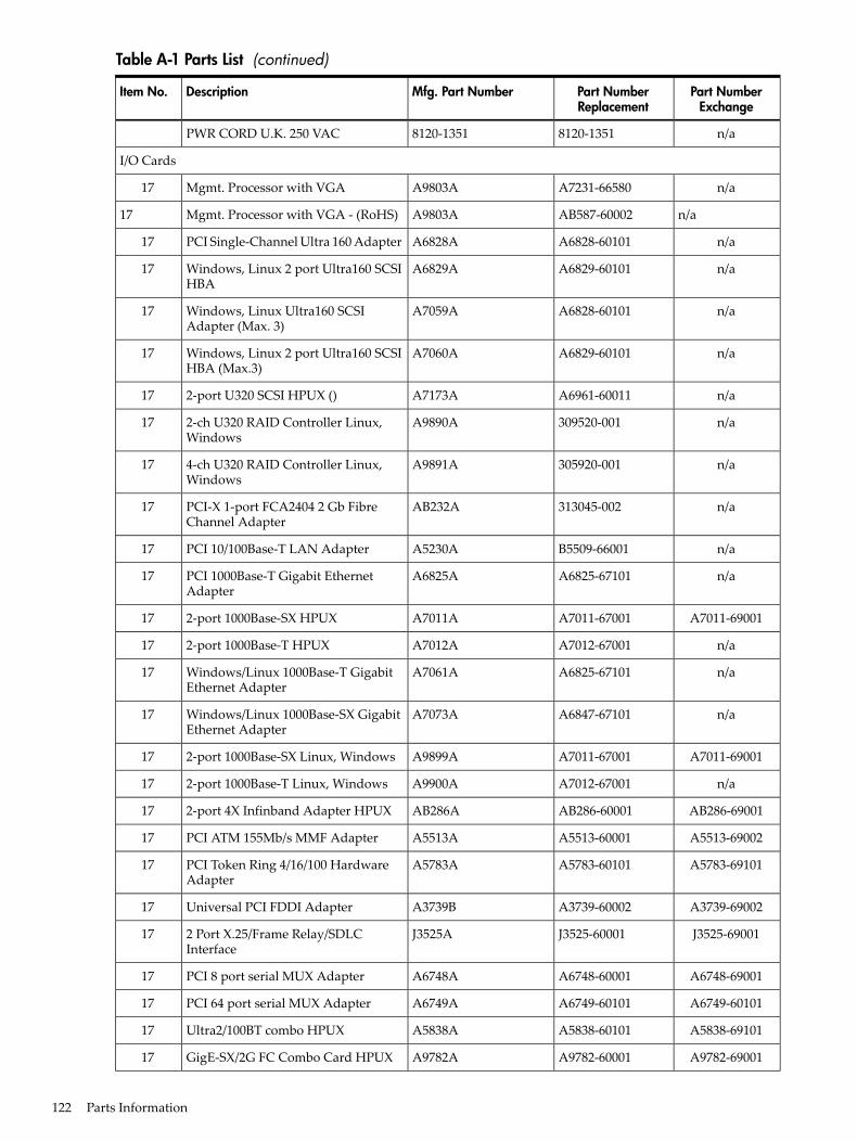
Table A-1 Parts List (continued)
Part NumberExchange
Part NumberReplacement
Mfg. Part NumberDescriptionItem No.
n/a8120-13518120-1351PWR CORD U.K. 250 VAC
I/O Cards
n/aA7231-66580A9803AMgmt. Processor with VGA17
n/aAB587-60002A9803AMgmt. Processor with VGA - (RoHS)17
n/aA6828-60101A6828APCI Single-Channel Ultra 160 Adapter17
n/aA6829-60101A6829AWindows, Linux 2 port Ultra160 SCSIHBA
17
n/aA6828-60101A7059AWindows, Linux Ultra160 SCSIAdapter (Max. 3)
17
n/aA6829-60101A7060AWindows, Linux 2 port Ultra160 SCSIHBA (Max.3)
17
n/aA6961-60011A7173A2-port U320 SCSI HPUX ()17
n/a309520-001A9890A2-ch U320 RAID Controller Linux,Windows
17
n/a305920-001A9891A4-ch U320 RAID Controller Linux,Windows
17
n/a313045-002AB232APCI-X 1-port FCA2404 2 Gb FibreChannel Adapter
17
n/aB5509-66001A5230APCI 10/100Base-T LAN Adapter17
n/aA6825-67101A6825APCI 1000Base-T Gigabit EthernetAdapter
17
A7011-69001A7011-67001A7011A2-port 1000Base-SX HPUX17
n/aA7012-67001A7012A2-port 1000Base-T HPUX17
n/aA6825-67101A7061AWindows/Linux 1000Base-T GigabitEthernet Adapter
17
n/aA6847-67101A7073AWindows/Linux 1000Base-SX GigabitEthernet Adapter
17
A7011-69001A7011-67001A9899A2-port 1000Base-SX Linux, Windows17
n/aA7012-67001A9900A2-port 1000Base-T Linux, Windows17
AB286-69001AB286-60001AB286A2-port 4X Infinband Adapter HPUX17
A5513-69002A5513-60001A5513APCI ATM 155Mb/s MMF Adapter17
A5783-69101A5783-60101A5783APCI Token Ring 4/16/100 HardwareAdapter
17
A3739-69002A3739-60002A3739BUniversal PCI FDDI Adapter17
J3525-69001J3525-60001J3525A2 Port X.25/Frame Relay/SDLCInterface
17
A6748-69001A6748-60001A6748APCI 8 port serial MUX Adapter17
A6749-60101A6749-60101A6749APCI 64 port serial MUX Adapter17
A5838-69101A5838-60101A5838AUltra2/100BT combo HPUX17
A9782-69001A9782-60001A9782AGigE-SX/2G FC Combo Card HPUX17
122 Parts Information
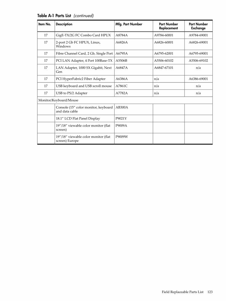
Table A-1 Parts List (continued)
Part NumberExchange
Part NumberReplacement
Mfg. Part NumberDescriptionItem No.
A9784-69001A9784-60001A8784AGigE-TX/2G FC Combo Card HPUX17
A6826-69001A6826-60001A6826A2-port 2 Gb FC HPUX, Linux,Windows
17
A6795-69001A6795-62001A6795AFibre Channel Card, 2 Gb, Single Port17
A5506-69102A5506-60102A5506BPCI LAN Adapter, 4 Port 100Base-TX17
n/aA6847-67101A6847ALAN Adapter, 1000 SX Gigabit, NextGen
17
A6386-69001n/aA6386APCI HyperFabric2 Fiber Adapter17
n/an/aA7861CUSB keyboard and USB scroll mouse17
n/an/aA7782AUSB to PS/2 Adapter17
Monitor/Keyboard/Mouse
AB300AConsole (15” color monitor, keyboardand data cable
P9021Y18.1” LCD Flat Panel Display
P9009A19”/18” viewable color monitor (flatscreen)
P9009W19”/18” viewable color monitor (flatscreen) Europe
Field Replaceable Parts List 123

124
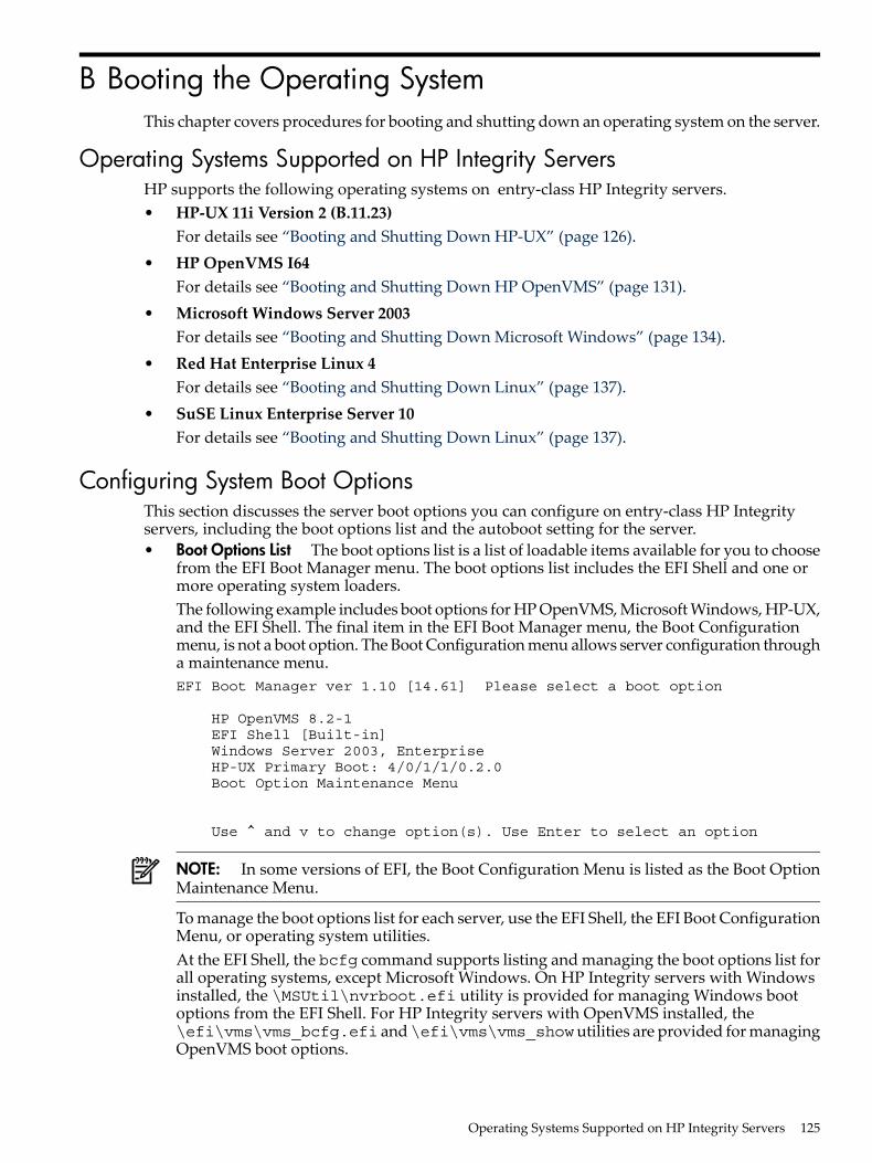
B Booting the Operating SystemThis chapter covers procedures for booting and shutting down an operating system on the server.
Operating Systems Supported on HP Integrity ServersHP supports the following operating systems on entry-class HP Integrity servers.• HP-UX 11i Version 2 (B.11.23)
For details see “Booting and Shutting Down HP-UX” (page 126).• HP OpenVMS I64
For details see “Booting and Shutting Down HP OpenVMS” (page 131).• Microsoft Windows Server 2003
For details see “Booting and Shutting Down Microsoft Windows” (page 134).• Red Hat Enterprise Linux 4
For details see “Booting and Shutting Down Linux” (page 137).• SuSE Linux Enterprise Server 10
For details see “Booting and Shutting Down Linux” (page 137).
Configuring System Boot OptionsThis section discusses the server boot options you can configure on entry-class HP Integrityservers, including the boot options list and the autoboot setting for the server.• Boot Options List The boot options list is a list of loadable items available for you to choose
from the EFI Boot Manager menu. The boot options list includes the EFI Shell and one ormore operating system loaders.The following example includes boot options for HP OpenVMS, Microsoft Windows, HP-UX,and the EFI Shell. The final item in the EFI Boot Manager menu, the Boot Configurationmenu, is not a boot option. The Boot Configuration menu allows server configuration througha maintenance menu.EFI Boot Manager ver 1.10 [14.61] Please select a boot option
HP OpenVMS 8.2-1 EFI Shell [Built-in] Windows Server 2003, Enterprise HP-UX Primary Boot: 4/0/1/1/0.2.0 Boot Option Maintenance Menu
Use ^ and v to change option(s). Use Enter to select an option
NOTE: In some versions of EFI, the Boot Configuration Menu is listed as the Boot OptionMaintenance Menu.
To manage the boot options list for each server, use the EFI Shell, the EFI Boot ConfigurationMenu, or operating system utilities.At the EFI Shell, the bcfg command supports listing and managing the boot options list forall operating systems, except Microsoft Windows. On HP Integrity servers with Windowsinstalled, the \MSUtil\nvrboot.efi utility is provided for managing Windows bootoptions from the EFI Shell. For HP Integrity servers with OpenVMS installed, the\efi\vms\vms_bcfg.efi and\efi\vms\vms_showutilities are provided for managingOpenVMS boot options.
Operating Systems Supported on HP Integrity Servers 125
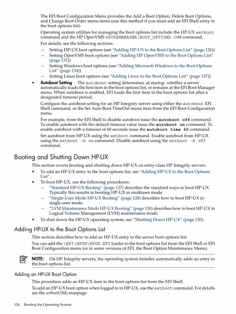
The EFI Boot Configuration Menu provides the Add a Boot Option, Delete Boot Options,and Change Boot Order menu items (use this method if you must add an EFI Shell entry tothe boot options list).Operating system utilities for managing the boot options list include the HP-UX setbootcommand and the HP OpenVMS @SYS$MANAGER:BOOT_OPTIONS.COM command.For details, see the following sections:— Setting HP-UX boot options (see “Adding HP-UX to the Boot Options List” (page 126))— Setting OpenVMS boot options (see “Adding HP OpenVMS to the Boot Options List”
(page 131))— Setting Windows boot options (see “Adding Microsoft Windows to the Boot Options
List” (page 134))— Setting Linux boot options (see “Adding Linux to the Boot Options List” (page 137))
• Autoboot Setting The autoboot setting determines, at startup, whether a serverautomatically loads the first item in the boot options list, or remains at the EFI Boot Managermenu. When autoboot is enabled, EFI loads the first item in the boot options list after adesignated timeout period.Configure the autoboot setting for an HP Integrity server using either the autoboot EFIShell command, or the Set Auto Boot TimeOut menu item from the EFI Boot Configurationmenu.For example, from the EFI Shell to disable autoboot issue the autoboot off command.To enable autoboot with the default timeout value issue the autoboot on command. Toenable autoboot with a timeout of 60 seconds issue the autoboot time 60 command.Set autoboot from HP-UX using the setboot command. Enable autoboot from HP-UXusing the setboot -b on command. Disable autoboot using the setboot -b offcommand.
Booting and Shutting Down HP-UXThis section covers booting and shutting down HP-UX on entry-class HP Integrity servers.• To add an HP-UX entry to the boot options list, see “Adding HP-UX to the Boot Options
List”.• To boot HP-UX, use the following procedures:
— “Standard HP-UX Booting” (page 127) describes the standard ways to boot HP-UX.Typically this results in booting HP-UX in multiuser mode.
— “Single-User Mode HP-UX Booting” (page 128) describes how to boot HP-UX insingle-user mode.
— “LVM Maintenance Mode HP-UX Booting” (page 130) describes how to boot HP-UX inLogical Volume Management (LVM) maintenance mode.
• To shut down the HP-UX operating system, see “Shutting Down HP-UX” (page 130).
Adding HP-UX to the Boot Options ListThis section describes how to add an HP-UX entry to the server boot options list.You can add the \EFI\HPUX\HPUX.EFI loader to the boot options list from the EFI Shell or EFIBoot Configuration menu (or in some versions of EFI, the Boot Option Maintenance Menu).
NOTE: On HP Integrity servers, the operating system installer automatically adds an entry tothe boot options list.
Adding an HP-UX Boot OptionThis procedure adds an HP-UX item to the boot options list from the EFI Shell.To add an HP-UX boot option when logged in to HP-UX, use the setboot command. For detailssee the setboot(1M) manpage.
126 Booting the Operating System

1. Access the EFI Shell environment.a. To access the server console, log in to iLO and enter CO.b. When accessing the console, confirm that you are at the EFI Boot Manager menu (the
main EFI menu). If you are at another EFI menu, choose Exit from the submenus untilyou return to the screen with the EFI Boot Manager heading.
c. To access the EFI Shell environment, choose EFI Shell from the EFI Boot Manager menu.2. Access the EFI System Partition (fsX: where X is the file system number) for the device
from which you want to boot HP-UX.For example, enter fs2: to access the EFI System Partition for the bootable file systemnumber 2. The EFI Shell prompt changes to reflect the file system currently accessed.The full path for the HP-UX loader is\EFI\HPUX\HPUX.EFI and it should be on the deviceyou are accessing.
3. At the EFI Shell environment, use the bcfg command to manage the boot options list.The bcfg command includes the following options for managing the boot options list:• bcfg boot dump — Display all items in the boot options list for the server.• bcfg boot rm # — Remove the item number specified by # from the boot options
list.• bcfg boot mv #a #b — Move the item number specified by #a to the position specified
by #b in the boot options list.• bcfg boot add # file.efi "Description" — Add a new boot option to the position in
the boot options list specified by #. The new boot option references file.efi and is listedwith the title specified by Description.For example, bcfg boot add 1 \EFI\HPUX\HPUX.EFI "HP-UX 11i"adds anHP-UX 11i item as the first entry in the boot options list.
For details, see the help bcfg command.4. Exit the console and iLO interfaces if you are finished using them.
To exit the server console and return to the iLO MP Main Menu, press Ctrl+B. To exit iLO,enter X at the Main Menu.
Standard HP-UX BootingUse either of the following procedures to boot HP-UX:• “Booting HP-UX (EFI Boot Manager)” (page 127)• “Booting HP-UX (EFI Shell)” (page 128)Procedure B-2 Booting HP-UX (EFI Boot Manager)From the EFI Boot Manager Menu, choose an item from the boot options list to boot HP-UX.1. Access the EFI Boot Manager Menu for the server on which you want to boot HP-UX.
a. To access the server console, log in to iLO and enter CO.b. When accessing the console, confirm that you are at the EFI Boot Manager menu (the
main EFI menu). If you are at another EFI menu, choose Exit from the submenus untilyou return to the screen with the EFI Boot Manager heading.
c. To access the EFI Shell environment, choose EFI Shell from the EFI Boot Manager menu.2. At the EFI Boot Manager menu, choose an item from the boot options list.
Each item in the boot options list references a specific boot device and provides a specificset of boot options or arguments you use when booting the device.
3. Press Enter to initiate booting using the chosen boot option.4. Exit the console and iLO MP interfaces when finished using them.
To exit the server console and return to the iLO MP Main Menu, press Ctrl+B. To exit theiLO MP, enter X at the Main Menu.
Booting and Shutting Down HP-UX 127
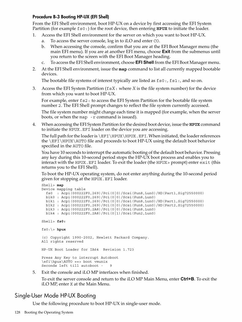
Procedure B-3 Booting HP-UX (EFI Shell)From the EFI Shell environment, boot HP-UX on a device by first accessing the EFI SystemPartition (for example fs0:) for the root device, then entering HPUX to initiate the loader.1. Access the EFI Shell environment for the server on which you want to boot HP-UX.
a. To access the server console, log in to iLO and enter CO.b. When accessing the console, confirm that you are at the EFI Boot Manager menu (the
main EFI menu). If you are at another EFI menu, choose Exit from the submenus untilyou return to the screen with the EFI Boot Manager heading.
c. To access the EFI Shell environment, choose EFI Shell from the EFI Boot Manager menu.2. At the EFI Shell environment, issue the map command to list all currently mapped bootable
devices.The bootable file systems of interest typically are listed as fs0:, fs1:, and so on.
3. Access the EFI System Partition (fsX: where X is the file system number) for the devicefrom which you want to boot HP-UX.For example, enter fs2: to access the EFI System Partition for the bootable file systemnumber 2. The EFI Shell prompt changes to reflect the file system currently accessed.The file system number might change each time it is mapped (for example, when the serverboots, or when the map -r command is issued).
4. When accessing the EFI System Partition for the desired boot device, issue theHPUX commandto initiate the HPUX.EFI loader on the device you are accessing.The full path for the loader is\EFI\HPUX\HPUX.EFI. When initiated, the loader referencesthe \EFI\HPUX\AUTO file and proceeds to boot HP-UX using the default boot behaviorspecified in the AUTO file.You have 10 seconds to interrupt the automatic booting of the default boot behavior. Pressingany key during this 10-second period stops the HP-UX boot process and enables you tointeract with the HPUX.EFI loader. To exit the loader (the HPUX> prompt) enter exit (thisreturns you to the EFI Shell).To boot the HP-UX operating system, do not enter anything during the 10-second periodgiven for stopping at the HPUX.EFI loader.Shell> mapDevice mapping table fs0 : Acpi(000222F0,269)/Pci(0|0)/Scsi(Pun8,Lun0)/HD(Part1,Sig72550000) blk0 : Acpi(000222F0,269)/Pci(0|0)/Scsi(Pun8,Lun0) blk1 : Acpi(000222F0,269)/Pci(0|0)/Scsi(Pun8,Lun0)/HD(Part1,Sig72550000) blk2 : Acpi(000222F0,269)/Pci(0|0)/Scsi(Pun8,Lun0)/HD(Part2,Sig72550000) blk3 : Acpi(000222F0,2A8)/Pci(0|0)/Scsi(Pun8,Lun0) blk4 : Acpi(000222F0,2A8)/Pci(0|1)/Scsi(Pun2,Lun0)
Shell> fs0:
fs0:\> hpux
(c) Copyright 1990-2002, Hewlett Packard Company.All rights reserved
HP-UX Boot Loader for IA64 Revision 1.723
Press Any Key to interrupt Autoboot\efi\hpux\AUTO ==> boot vmunixSeconds left till autoboot - 9
5. Exit the console and iLO MP interfaces when finished.To exit the server console and return to the iLO MP Main Menu, enter Ctrl+B. To exit theiLO MP, enter X at the Main Menu.
Single-User Mode HP-UX BootingUse the following procedure to boot HP-UX in single-user mode.
128 Booting the Operating System
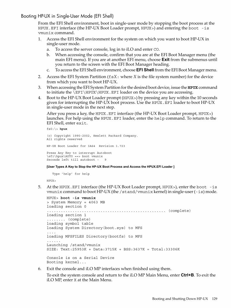
Booting HP-UX in Single-User Mode (EFI Shell)From the EFI Shell environment, boot in single-user mode by stopping the boot process at theHPUX.EFI interface (the HP-UX Boot Loader prompt, HPUX>) and entering the boot -isvmunix command.1. Access the EFI Shell environment for the system on which you want to boot HP-UX in
single-user mode.a. To access the server console, log in to iLO and enter CO.b. When accessing the console, confirm that you are at the EFI Boot Manager menu (the
main EFI menu). If you are at another EFI menu, choose Exit from the submenus untilyou return to the screen with the EFI Boot Manager heading.
c. To access the EFI Shell environment, choose EFI Shell from the EFI Boot Manager menu.2. Access the EFI System Partition (fsX: where X is the file system number) for the device
from which you want to boot HP-UX.3. When accessing the EFI System Partition for the desired boot device, issue theHPUX command
to initiate the \EFI\HPUX\HPUX.EFI loader on the device you are accessing.4. Boot to the HP-UX Boot Loader prompt (HPUX>) by pressing any key within the 10 seconds
given for interrupting the HP-UX boot process. Use the HPUX.EFI loader to boot HP-UXin single-user mode in the next step.After you press a key, the HPUX.EFI interface (the HP-UX Boot Loader prompt, HPUX>)launches. For help using the HPUX.EFI loader, enter the help command. To return to theEFI Shell, enter exit.fs0:\> hpux
(c) Copyright 1990-2002, Hewlett Packard Company.All rights reserved
HP-UX Boot Loader for IA64 Revision 1.723
Press Any Key to interrupt Autoboot\efi\hpux\AUTO ==> boot vmunixSeconds left till autoboot - 9
[User Types A Key to Stop the HP-UX Boot Process and Access the HPUX.EFI Loader ]
Type ’help’ for help
HPUX>
5. At the HPUX.EFI interface (the HP-UX Boot Loader prompt, HPUX>), enter the boot -isvmunix command to boot HP-UX (the /stand/vmunix kernel) in single-user (-is) mode.HPUX> boot -is vmunix> System Memory = 4063 MBloading section 0................................................... (complete)loading section 1........ (complete)loading symbol tableloading System Directory(boot.sys) to MFS....loading MFSFILES Directory(bootfs) to MFS......Launching /stand/vmunixSIZE: Text:25953K + Data:3715K + BSS:3637K = Total:33306K
Console is on a Serial DeviceBooting kernel...
6. Exit the console and iLO MP interfaces when finished using them.To exit the system console and return to the iLO MP Main Menu, enter Ctrl+B. To exit theiLO MP, enter X at the Main Menu.
Booting and Shutting Down HP-UX 129

LVM Maintenance Mode HP-UX BootingUse the following procedure to boot HP-UX in Logical Volume Management (LVM) maintenancemode.
Booting HP-UX in LVM-Maintenance Mode (EFI Shell)From the EFI Shell environment, boot in LVM-maintenance mode by stopping the boot processat the HPUX.EFI interface (the HP-UX Boot Loader prompt, HPUX>) and entering the boot -lmvmunix command.1. Access the EFI Shell environment for the system on which you want to boot HP-UX in
LVM-maintenance mode.a. To access the server console, log in to iLO and enter CO.b. When accessing the console, confirm that you are at the EFI Boot Manager menu (the
main EFI menu). If you are at another EFI menu, choose Exit from the submenus untilyou return to the screen with the EFI Boot Manager heading.
c. To access the EFI Shell environment, choose EFI Shell from the EFI Boot Manager menu.2. Access the EFI System Partition (fsX: where X is the file system number) for the device
from which you want to boot HP-UX.3. When accessing the EFI System Partition for the desired boot device, issue theHPUX command
to initiate the \EFI\HPUX\HPUX.EFI loader on the device you are accessing.4. Press any key within the 10 seconds given for interrupting the HP-UX boot process. This
stops the boot process at the HPUX.EFI interface (the HP-UX Boot Loader prompt, HPUX>).5. At the HPUX.EFI interface, enter the boot -lm vmunix command to boot HP-UX (the
/stand/vmunix kernel) in LVM-maintenance (-lm) mode.6. Exit the console and iLO MP interfaces when finished using them.
To exit the system console and return to the iLO MP Main Menu, press Ctrl+B. To exit theiLO MP, enter X at the Main Menu.
Shutting Down HP-UXTo shut down HP-UX running on a system, use theshutdown command. You have the followingoptions when shutting down HP-UX:• To shut down and reboot an HP-UX system, use the shutdown -r command.• To shut down and halt (power off) an HP-UX system, use the shutdown -h command.For details see the shutdown(1M) manpage and the following procedure:
Shutting Down HP-UX (/sbin/shutdown Command)From the HP-UX command line, issue theshutdown command to shut down the HP-UX operatingsystem.1. Log in to HP-UX running on the system that you want to shut down.
Log in to iLO for the server and use the Console menu to access the system console. Accessingthe console through iLO enables you to maintain console access to the server after HP-UXhas shut down.
2. Issue the shutdown command with the appropriate command-line options.The command-line options you specify dictate the way in which HP-UX shuts down, andwhether the server is rebooted.Use the following list to choose an HP-UX shutdown option for your server:• To shut down HP-UX and halt (power off) the server, issue theshutdown -h command.
To reboot a halted server, you must power on the server using the PC command at theiLO MP Command menu.
• To shut down HP-UX and reboot the server, issue the shutdown -r command.
130 Booting the Operating System

Booting and Shutting Down HP OpenVMSThis section has procedures for booting and shutting down HP OpenVMS on entry-class HPIntegrity servers, and procedures for adding HP OpenVMS to the boot options list.• To add an HP OpenVMS entry to the boot options list, see “Adding HP OpenVMS to the
Boot Options List” (page 131).• To boot HP OpenVMS on an entry-class HP Integrity server, see “Booting HP OpenVMS”
(page 132).• To shut down HP OpenVMS, see “Shutting Down HP OpenVMS” (page 133).
Adding HP OpenVMS to the Boot Options ListOn HP Integrity servers, you can use the following procedures to manage boot options list entriesfor HP OpenVMS.You can add the \efi\vms\vms_loader.efi loader to the boot options list from the EFI Shellor EFI Boot Configuration Menu (or in some versions of EFI, the Boot Option Maintenance Menu).
NOTE: On HP Integrity servers, the operating system installer automatically adds an entry tothe boot options list.
Adding an HP OpenVMS Boot OptionThis procedure adds an HP OpenVMS item to the boot options list from the EFI Shell.To add an HP OpenVMS boot option when logged in to OpenVMS, use the@SYS$MANAGER:BOOT_OPTIONS.COM command.1. Access the EFI Shell environment.
a. To access the server console, log in to iLO and enter CO.b. When accessing the console, confirm that you are at the EFI Boot Manager menu (the
main EFI menu). If you are at another EFI menu, choose Exit from the submenus untilyou return to the screen with the EFI Boot Manager heading.
c. To access the EFI Shell environment, choose EFI Shell from the EFI Boot Manager menu.2. Access the EFI System Partition (fsX: where X is the file system number) for the device
from which you want to boot HP OpenVMS.For example, enter fs2: to access the EFI System Partition for the bootable file systemnumber 2. The EFI Shell prompt changes to reflect the file system currently accessed.The full path for the HP OpenVMS loader is \efi\vms\vms_loader.efi and it shouldbe on the device you are accessing.
3. At the EFI Shell environment, use the bcfg command to manage the boot options list.You can also accomplish this step by using the \efi\vms\vms_bcfg.efi and\efi\vms\vms_show.efi utilities, which are available on the EFI System Partition forHP OpenVMS. Both vms_bcfg and vms_show are unique utilities for OpenVMS I64. Thevms_bcfg utility differs from the bcfg EFI command in that vms_bcfg enables you tospecify boot devices using VMS-style device names.The bcfg command includes the following options for managing the boot options list:• bcfg boot dump — Displays all items in the boot options list for the server.• bcfg boot rm # — Removes the item number specified by # from the boot options
list.
Booting and Shutting Down HP OpenVMS 131

• bcfg boot mv #a #b — Moves the item number specified by #a to the positionspecified by #b in the boot options list.
• bcfg boot add # file.efi "Description" — Adds a new boot option to the positionin the boot options list specified by #. The new boot option references file.efi and is listedwith the title specified by Description.For example,bcfg boot add 1 \efi\vms\vms_loader.efi "HP OpenVMS"addsan HP OpenVMS item as the first entry in the boot options list.
For details, see the help bcfg command.4. Exit the console and iLO MP interfaces if you are finished using them.
To exit the system console and return to the iLO MP Main Menu, press Ctrl+B. To exit iLO,enter X at the Main Menu.
Booting HP OpenVMSTo boot HP OpenVMS on an entry-class HP Integrity server, use either of the followingprocedures:• “Booting HP OpenVMS (EFI Boot Manager)” (page 132)• “Booting HP OpenVMS (EFI Shell)” (page 132)
Booting HP OpenVMS (EFI Boot Manager)From the EFI Boot Manager Menu, choose an item from the boot options list to boot HP OpenVMSusing the chosen boot option.1. Access the EFI Boot Manager menu for the server on which you want to boot HP OpenVMS.
a. To access the server console, log in to iLO and enter CO.b. When accessing the console, confirm that you are at the EFI Boot Manager menu (the
main EFI menu). If you are at another EFI menu, choose Exit from the submenus untilyou return to the screen with the EFI Boot Manager heading.
c. To access the EFI Shell environment, choose EFI Shell from the EFI Boot Manager menu.2. At the EFI Boot Manager menu, choose an item from the boot options list.
Each item in the boot options list references a specific boot device and provides a specificset of boot options or arguments to use when booting the device.
3. To initiate booting using the chosen boot option, press Enter.4. Exit the console and iLO MP interfaces when finished using them.
To exit the system console and return to the iLO MP Main Menu, enter Ctrl+B. To exit theiLO MP, enter X at the Main Menu.
Booting HP OpenVMS (EFI Shell)From the EFI Shell environment, to boot HP OpenVMS on a device first access the EFI SystemPartition (for example fs0:) for the root device and enter \efi\vms\vms_loader to initiatethe OpenVMS loader.1. Access the EFI Shell environment for the server on which you want to boot HP OpenVMS.
a. To access the server console, log in to iLO and enter CO.b. When accessing the console, confirm that you are at the EFI Boot Manager menu (the
main EFI menu). If you are at another EFI menu, choose Exit from the submenus untilyou return to the screen with the EFI Boot Manager heading.
c. To access the EFI Shell environment, choose EFI Shell from the EFI Boot Manager menu.2. At the EFI Shell environment, issue the map command to list all currently mapped bootable
devices.The bootable file systems of interest typically are listed as fs0:, fs1:, and so on.
132 Booting the Operating System
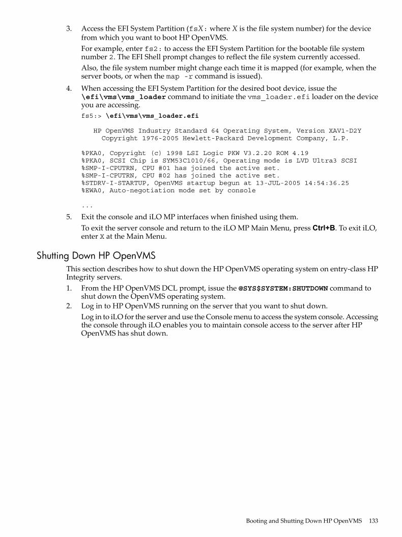
3. Access the EFI System Partition (fsX: where X is the file system number) for the devicefrom which you want to boot HP OpenVMS.For example, enter fs2: to access the EFI System Partition for the bootable file systemnumber 2. The EFI Shell prompt changes to reflect the file system currently accessed.Also, the file system number might change each time it is mapped (for example, when theserver boots, or when the map -r command is issued).
4. When accessing the EFI System Partition for the desired boot device, issue the\efi\vms\vms_loader command to initiate the vms_loader.efi loader on the deviceyou are accessing.fs5:> \efi\vms\vms_loader.efi
HP OpenVMS Industry Standard 64 Operating System, Version XAV1-D2Y Copyright 1976-2005 Hewlett-Packard Development Company, L.P.
%PKA0, Copyright (c) 1998 LSI Logic PKW V3.2.20 ROM 4.19%PKA0, SCSI Chip is SYM53C1010/66, Operating mode is LVD Ultra3 SCSI%SMP-I-CPUTRN, CPU #01 has joined the active set.%SMP-I-CPUTRN, CPU #02 has joined the active set.%STDRV-I-STARTUP, OpenVMS startup begun at 13-JUL-2005 14:54:36.25%EWA0, Auto-negotiation mode set by console
...
5. Exit the console and iLO MP interfaces when finished using them.To exit the server console and return to the iLO MP Main Menu, press Ctrl+B. To exit iLO,enter X at the Main Menu.
Shutting Down HP OpenVMSThis section describes how to shut down the HP OpenVMS operating system on entry-class HPIntegrity servers.1. From the HP OpenVMS DCL prompt, issue the @SYS$SYSTEM:SHUTDOWN command to
shut down the OpenVMS operating system.2. Log in to HP OpenVMS running on the server that you want to shut down.
Log in to iLO for the server and use the Console menu to access the system console. Accessingthe console through iLO enables you to maintain console access to the server after HPOpenVMS has shut down.
Booting and Shutting Down HP OpenVMS 133
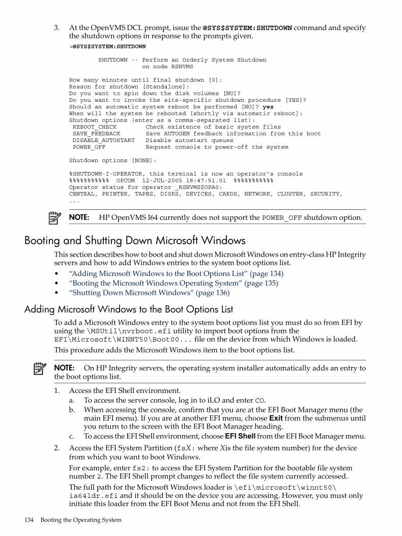
3. At the OpenVMS DCL prompt, issue the @SYS$SYSTEM:SHUTDOWN command and specifythe shutdown options in response to the prompts given.>@SYS$SYSTEM:SHUTDOWN
SHUTDOWN -- Perform an Orderly System Shutdown on node RSNVMS
How many minutes until final shutdown [0]: Reason for shutdown [Standalone]: Do you want to spin down the disk volumes [NO]? Do you want to invoke the site-specific shutdown procedure [YES]? Should an automatic system reboot be performed [NO]? yesWhen will the system be rebooted [shortly via automatic reboot]: Shutdown options (enter as a comma-separated list): REBOOT_CHECK Check existence of basic system files SAVE_FEEDBACK Save AUTOGEN feedback information from this boot DISABLE_AUTOSTART Disable autostart queues POWER_OFF Request console to power-off the system
Shutdown options [NONE]:
%SHUTDOWN-I-OPERATOR, this terminal is now an operator’s console%%%%%%%%%%% OPCOM 12-JUL-2005 18:47:51.01 %%%%%%%%%%%Operator status for operator _RSNVMS$OPA0:CENTRAL, PRINTER, TAPES, DISKS, DEVICES, CARDS, NETWORK, CLUSTER, SECURITY,...
NOTE: HP OpenVMS I64 currently does not support the POWER_OFF shutdown option.
Booting and Shutting Down Microsoft WindowsThis section describes how to boot and shut down Microsoft Windows on entry-class HP Integrityservers and how to add Windows entries to the system boot options list.• “Adding Microsoft Windows to the Boot Options List” (page 134)• “Booting the Microsoft Windows Operating System” (page 135)• “Shutting Down Microsoft Windows” (page 136)
Adding Microsoft Windows to the Boot Options ListTo add a Microsoft Windows entry to the system boot options list you must do so from EFI byusing the \MSUtil\nvrboot.efi utility to import boot options from theEFI\Microsoft\WINNT50\Boot00... file on the device from which Windows is loaded.This procedure adds the Microsoft Windows item to the boot options list.
NOTE: On HP Integrity servers, the operating system installer automatically adds an entry tothe boot options list.
1. Access the EFI Shell environment.a. To access the server console, log in to iLO and enter CO.b. When accessing the console, confirm that you are at the EFI Boot Manager menu (the
main EFI menu). If you are at another EFI menu, choose Exit from the submenus untilyou return to the screen with the EFI Boot Manager heading.
c. To access the EFI Shell environment, choose EFI Shell from the EFI Boot Manager menu.2. Access the EFI System Partition (fsX: where Xis the file system number) for the device
from which you want to boot Windows.For example, enter fs2: to access the EFI System Partition for the bootable file systemnumber 2. The EFI Shell prompt changes to reflect the file system currently accessed.The full path for the Microsoft Windows loader is \efi\microsoft\winnt50\ia64ldr.efi and it should be on the device you are accessing. However, you must onlyinitiate this loader from the EFI Boot Menu and not from the EFI Shell.
134 Booting the Operating System
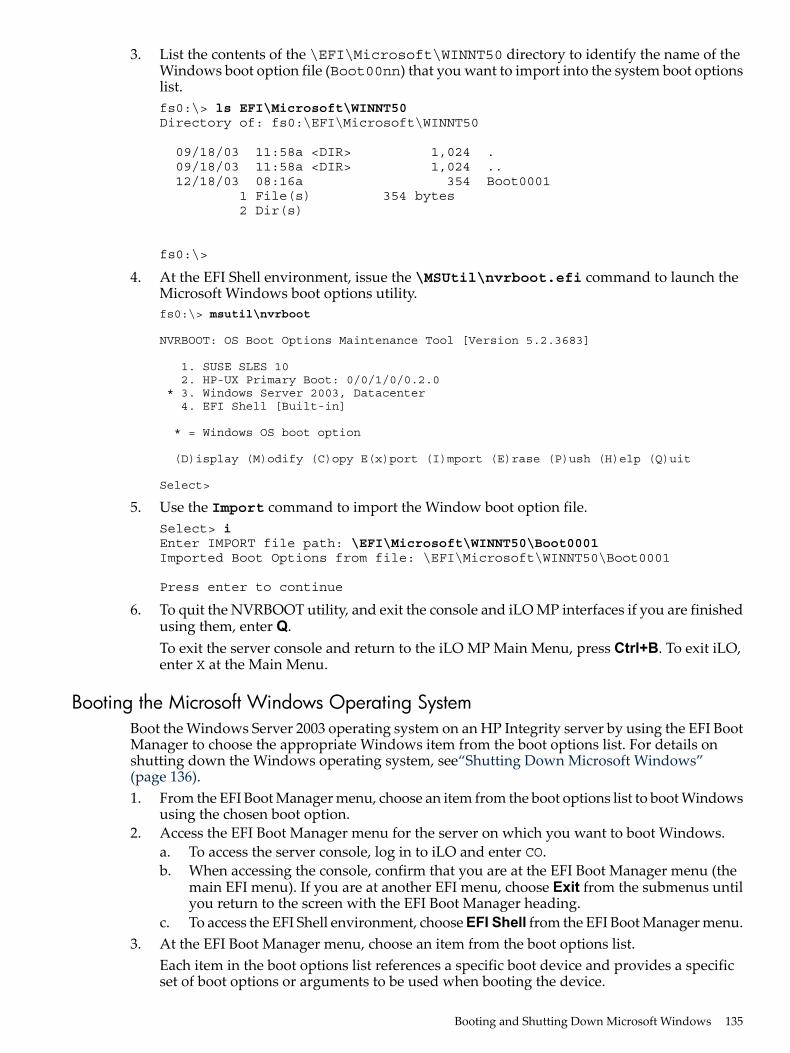
3. List the contents of the \EFI\Microsoft\WINNT50 directory to identify the name of theWindows boot option file (Boot00nn) that you want to import into the system boot optionslist.fs0:\> ls EFI\Microsoft\WINNT50Directory of: fs0:\EFI\Microsoft\WINNT50
09/18/03 11:58a <DIR> 1,024 . 09/18/03 11:58a <DIR> 1,024 .. 12/18/03 08:16a 354 Boot0001 1 File(s) 354 bytes 2 Dir(s)
fs0:\>
4. At the EFI Shell environment, issue the \MSUtil\nvrboot.efi command to launch theMicrosoft Windows boot options utility.fs0:\> msutil\nvrboot
NVRBOOT: OS Boot Options Maintenance Tool [Version 5.2.3683]
1. SUSE SLES 10 2. HP-UX Primary Boot: 0/0/1/0/0.2.0 * 3. Windows Server 2003, Datacenter 4. EFI Shell [Built-in]
* = Windows OS boot option
(D)isplay (M)odify (C)opy E(x)port (I)mport (E)rase (P)ush (H)elp (Q)uit
Select>
5. Use the Import command to import the Window boot option file.Select> iEnter IMPORT file path: \EFI\Microsoft\WINNT50\Boot0001Imported Boot Options from file: \EFI\Microsoft\WINNT50\Boot0001
Press enter to continue
6. To quit the NVRBOOT utility, and exit the console and iLO MP interfaces if you are finishedusing them, enter Q.To exit the server console and return to the iLO MP Main Menu, press Ctrl+B. To exit iLO,enter X at the Main Menu.
Booting the Microsoft Windows Operating SystemBoot the Windows Server 2003 operating system on an HP Integrity server by using the EFI BootManager to choose the appropriate Windows item from the boot options list. For details onshutting down the Windows operating system, see“Shutting Down Microsoft Windows”(page 136).1. From the EFI Boot Manager menu, choose an item from the boot options list to boot Windows
using the chosen boot option.2. Access the EFI Boot Manager menu for the server on which you want to boot Windows.
a. To access the server console, log in to iLO and enter CO.b. When accessing the console, confirm that you are at the EFI Boot Manager menu (the
main EFI menu). If you are at another EFI menu, choose Exit from the submenus untilyou return to the screen with the EFI Boot Manager heading.
c. To access the EFI Shell environment, choose EFI Shell from the EFI Boot Manager menu.3. At the EFI Boot Manager menu, choose an item from the boot options list.
Each item in the boot options list references a specific boot device and provides a specificset of boot options or arguments to be used when booting the device.
Booting and Shutting Down Microsoft Windows 135
4. Press Enter to initiate booting using the chosen boot option.5. After Windows begins loading, wait for the Special Administration Console (SAC) to become
available.The SAC interface provides a text-based administration tool that is available from the systemconsole. For details see the SAC online help (enter ? at the SAC> prompt).Loading.: Windows Server 2003, DatacenterStarting: Windows Server 2003, Datacenter
Starting Windows...********************************************************************************
Computer is booting, SAC started and initialized.
Use the "ch -?" command for information about using channels.Use the "?" command for general help.
SAC>
6. Exit the console and iLO MP interfaces when finished using them.To exit the server console and return to the iLO MP Main Menu, press Ctrl+B. To exit iLO,enter X at the Main Menu.
Shutting Down Microsoft WindowsShut down the Windows operating system on HP Integrity servers by using the Start menu orthe shutdown command.
CAUTION: Do not shut down Windows using Special Administration Console (SAC) restartor shutdown commands under normal circumstances.Issuing restart or shutdown at the SAC> prompt causes the server to restart or shutdownimmediately and can result in the loss of data.Instead use the Windows Start menu or the shutdown command to shut down gracefully.
To shut down Windows use either of the following methods.• Choose Shut Down from the Start menu and choose either Restart or Shut down from the
pull-down menu.The Restart menu item shuts down and restarts the server. The Shut down menu item shutsdown the server.You can use this method when using a graphical interface to the server.
• Issue the shutdown command from the Windows command line.You can issue this command from a command prompt through the Special AdministrationConsole (SAC) or from any other command line.The Windows shutdown command includes the following options:/s Shuts down and halts (power off) the server. This is the equivalent of
Start—>Shut Down, Shut down. To power on the server, use the iLO MP PCcommand.
/r Shuts down and restarts the server. This is the equivalent of Start—>Shut Down,Restart.
/a Aborts a server shutdown./t xxx Sets the timeout period before shutdown to xxx seconds. The timeout period
ranges from 0–600, with a default of 30.For details, see the help shutdown Windows command.
136 Booting the Operating System
Windows Shutdown from the Command LineFrom the Windows command line, issue the shutdown command to shut down the operatingsystem.1. Log in to Windows running on the server that you want to shut down.
For example, access the system console and use the Windows SAC interface to start acommand prompt, from which you can issue Windows commands to shut down the server.
2. Check to see whether any users are logged in.Use the query user or query session command.
3. Issue the shutdown command and the appropriate options to shut down the WindowsServer 2003 on the server.You have the following options when shutting down Windows:• To shut down Windows and reboot:
shutdown /r or choose the Start —> Shut Down action and choose Restart from thepull-down menu.
• To shut down Windows and halt (power off server hardware):shutdown /s or choose the Start —> Shut Down action and choose Shut down fromthe pull-down menu.To reboot a halted server you must power on the server using the PC command at theiLO MP Command menu.
• To abort a shutdown (stop a shutdown that has been initiated): shutdown /aFor example:
shutdown /r /t 60 /c "Shut down in one minute."
This command initiates a Windows system shutdown and reboot after a timeout period of60 seconds. The /c option specifies a message that is broadcast to any other users.
Booting and Shutting Down LinuxThis section covers booting and shutting down Linux on entry-class HP servers. Procedures forRed Hat Enterprise Linux and SuSE Linux Enterprise Server are given in this section.• To add a Linux entry to the boot options list, see “Adding Linux to the Boot Options List”
(page 137).• To boot Linux on entry-class HP Integrity servers, use the following procedures.
— For details on Red Hat Enterprise Linux, see “Booting the Red Hat Enterprise LinuxOperating System” (page 138) .
— For details on SuSE Linux Enterprise Server, see “Booting the SuSE Linux EnterpriseServer Operating System” (page 139) .
• To shut down either Red Hat Enterprise Linux or SuSE Linux Enterprise Server, see “ShuttingDown Linux” (page 140).
Adding Linux to the Boot Options ListThis section describes how to add a Linux entry to the system boot options list. The processesfor adding both Red Hat Enterprise Linux and SuSE Linux Enterprise Servers are given here.You can add the \EFI\redhat\elilo.efi loader or the \efi\SuSE\elilo.efi loader tothe boot options list from the EFI Shell or EFI Boot Configuration menu (or in some versions ofEFI, the Boot Option Maintenance Menu).
Booting and Shutting Down Linux 137
NOTE: On HP Integrity servers, the operating system installer automatically adds an entry tothe boot options list.
1. Access the EFI Shell environment.a. To access the server console, log in to iLO and enter CO.b. When accessing the console, confirm that you are at the EFI Boot Manager menu (the
main EFI menu). If you are at another EFI menu, choose Exit from the submenus untilyou return to the screen with the EFI Boot Manager heading.
c. To access the EFI Shell environment, choose EFI Shell from the EFI Boot Manager menu.2. Access the EFI System Partition (fsX: where X is the file system number) for the device
from which you want to boot Linux.For example, enter fs2: to access the EFI System Partition for the bootable file systemnumber 2. The EFI Shell prompt changes to reflect the file system currently accessed.The full path for the Red Hat Enterprise Linux loader is \EFI\redhat\elilo.efi and itshould be on the device you are accessing.The full path for the SuSE Linux Enterprise Server loader is \efi\SuSE\elilo.efi andit should be on the device you are accessing.
3. At the EFI Shell environment, use the bcfg command to manage the boot options list.The bcfg command includes the following options for managing the boot options list:• bcfg boot dump — Displays all items in the boot options list for the server.• bcfg boot rm # — Removes the item number specified by # from the boot options
list.• bcfg boot mv #a #b — Moves the item number specified by #a to the position
specified by #b in the boot options list.• bcfg boot add # file.efi "Description" — Adds a new boot option to the position
in the boot options list specified by #. The new boot option refers to file.efi and is listedwith the title specified by Description.For example, bcfg boot add 1 \EFI\redhat\elilo.efi "Red HatEnterprise Linux"adds a Red Hat Enterprise Linux item as the first entry in theboot options list.Likewise, bcfg boot add 1 \efi\SuSE\elilo.efi "SLES 10" adds a SuSELinux item as the first entry in the boot options list.
For details, see the help bcfg command.4. Exit the console and iLO interfaces if you are finished using them.
To exit the server console and return to the iLO MP Main Menu, press Ctrl+B. To exit iLO,enter X at the Main Menu.
Booting the Red Hat Enterprise Linux Operating SystemYou can boot the Red Hat Enterprise Linux operating system on HP Integrity servers using eitherof these methods:• Choose a Red Hat Enterprise Linux entry from the EFI Boot Manager menu.
To load the Red Hat Enterprise Linux operating system at the EFI Boot Manager menu,choose its entry from the list of boot options.Choosing a Linux entry from the boot options list boots the operating system usingELILO.EFI loader and the elilo.conf file.
• Initiate the ELILO.EFI Linux loader from the EFI Shell.On a Red Hat Enterprise Linux boot device EFI System Partition, the full paths to the loaderand configuration files are as follows:
138 Booting the Operating System

\EFI\redhat\elilo.efi
\EFI\redhat\elilo.conf
After choosing the file system for the boot device (for example, fs0:) you can initiate theLinux loader from the EFI Shell prompt by entering the full path for the ELILO.EFI loader.
By default the ELILO.EFI loader boots Linux using the kernel image and parameters specifiedby the default entry in the elilo.conf file on the EFI System Partition for the boot device.To interact with the ELILO.EFI loader, interrupt the boot process (for example, enter a space)at the ELILO boot prompt. To exit the ELILO.EFI loader, use the exit command.
Booting Red Hat Enterprise Linux from the EFI ShellTo boot Red Hat Enterprise Linux from the EFI Shell:1. Access the EFI Shell.
From the system console, choose the EFI Shell entry from the EFI Boot Manager menu toaccess the shell.
2. Access the EFI System Partition for the Red Hat Enterprise Linux boot device.Use the map EFI Shell command to list the file systems (fs0, fs1, and so on) that are knownand mapped.To choose a file system to use, enter its mapped name followed by a colon (:). For example,to operate with the boot device that is mapped as fs3, enter fs3: at the EFI Shell prompt.
3. Enter ELILO at the EFI Shell command prompt to launch the ELILO.EFI loader.If needed, you can specify the full path by entering \EFI\redhat\elilo at the EFI Shellcommand prompt.
4. Allow the ELILO.EFI loader to proceed with booting the Red Hat Enterprise Linux kernel.By default, the ELILO.EFI loader boots the kernel image and options specified by thedefault item in the elilo.conf file.To interact with the ELILO.EFI loader, interrupt the boot process (for example, enter aspace) at the ELILO boot prompt. To exit the loader, use the exit command.
Booting the SuSE Linux Enterprise Server Operating SystemYou can boot the SuSE Linux Enterprise Server 10 operating system on HP Integrity serversusing either of these methods:• Choose a SuSE Linux Enterprise Server entry from the EFI Boot Manager menu.
To load the SuSE Linux Enterprise Server operating system at the EFI Boot Manager menu,choose its entry from the list of boot options.Choosing a Linux entry from the boot options list boots the operating system usingELILO.EFI loader and the elilo.conf file.
• Initiate the ELILO.EFI Linux loader from the EFI Shell. See “Booting SuSE Linux EnterpriseServer from the EFI Shell” (page 140).On a SuSE Linux Enterprise Server boot device EFI System Partition, the full paths to theloader and configuration files are as follows:\efi\SuSE\elilo.conf
After choosing the file system for the boot device (for example, fs0:) you can initiate theLinux loader from the EFI Shell prompt by entering the full path for the ELILO.EFI loader.
By default, the ELILO.EFI loader boots Linux using the kernel image and parameters specifiedby the default entry in the elilo.conf file on the EFI System Partition for the boot device.To interact with the ELILO.EFI loader, interrupt the boot process (for example, enter a space)at the ELILO boot prompt. To exit the ELILO.EFI loader, use the exit command.
Booting and Shutting Down Linux 139

Booting SuSE Linux Enterprise Server from the EFI ShellTo boot SuSE Linux Enterprise Server 10 from the EFI Shell:1. Access the EFI Shell.
From the system console, choose the EFI Shell entry from the EFI Boot Manager menu toaccess the shell.
2. Access the EFI System Partition for the SuSE Linux Enterprise Server boot device.Use the map EFI Shell command to list the file systems (fs0, fs1, and so on) that are knownand mapped.To choose a file system to use, enter its mapped name followed by a colon (:). For example,to operate with the boot device that is mapped as fs3, enter fs3: at the EFI Shell prompt.
3. Enter ELILO at the EFI Shell command prompt to launch the ELILO.EFI loader.If needed, you can specify the loader’s full path by entering \efi\SuSE\elilo at the EFIShell command prompt.
4. Allow the ELILO.EFI loader to proceed with booting the SuSE Linux kernel.By default, the ELILO.EFI loader boots the kernel image and options specified by thedefault item in the elilo.conf file.To interact with the ELILO.EFI loader, interrupt the boot process (for example, enter aspace) at the ELILO boot prompt. To exit the loader use the exit command.
Shutting Down LinuxUse the shutdown command to shut down Red Hat Enterprise Linux or SuSE Linux EnterpriseServer.The Red Hat Enterprise Linux and SuSE Linux Enterprise Server shutdown command has thefollowing options:-h Halts (powers off) after shutdown.
Use the PC command at the iLO MP Command menu to manually power on or poweroff server hardware, as needed.
-r Reboots after shutdown.-c Cancels an already running shutdown.time When to shut down. (Required.) You can specify time in the following ways:
• Absolute time in the format hh:mm, in which hh is the hour (one or two digits) andmm is the minute of the hour (two digits).
• Number of minutes to wait in the format +m, in which m is the number of minutes.• To immediately shut down, use the now command; this is equivalent to using +0
to wait zero minutes.See the shutdown(8) Linux manpage. Also see the Linux manpage for the poweroff command.1. From the command line for Red Hat Enterprise Linux or SuSE Linux Enterprise Server, issue
the shutdown command to shut down the operating system.2. Log in to Linux running on the server you want to shut down.3. Issue the shutdown command with the desired command-line options, and include the
required time argument to specify when the operating system shutdown is to occur.For example, shutdown -r +20 shuts down and reboots the server in 20 minutes.
140 Booting the Operating System
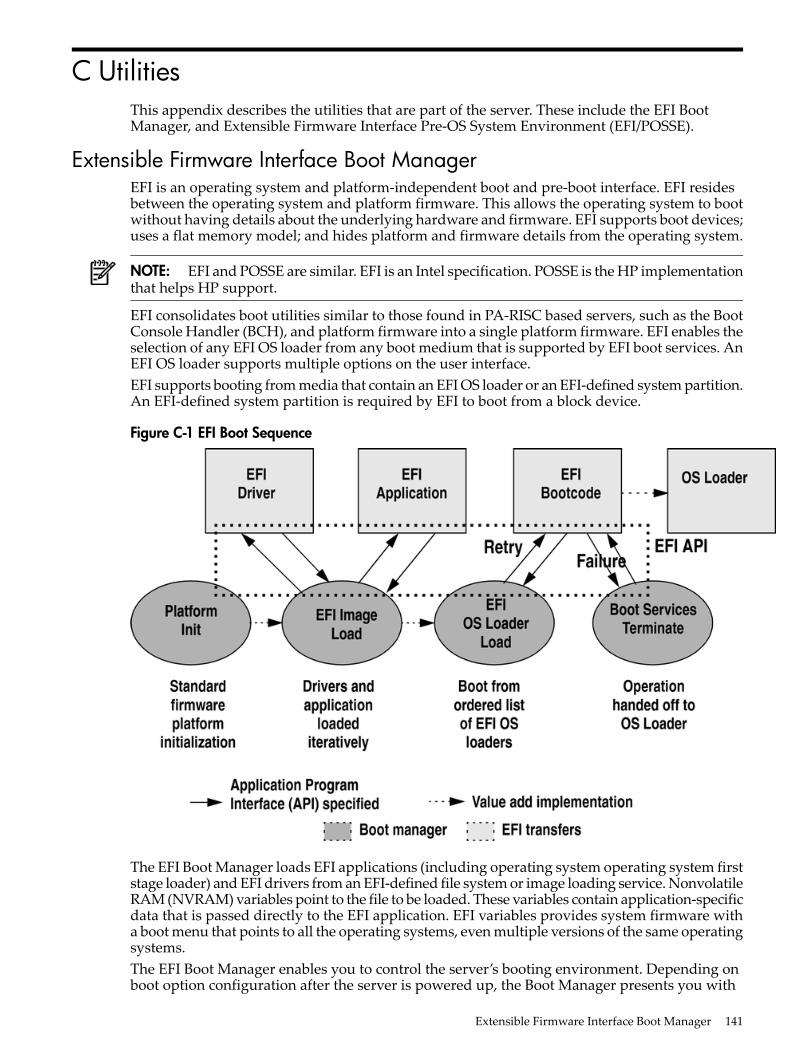
C UtilitiesThis appendix describes the utilities that are part of the server. These include the EFI BootManager, and Extensible Firmware Interface Pre-OS System Environment (EFI/POSSE).
Extensible Firmware Interface Boot ManagerEFI is an operating system and platform-independent boot and pre-boot interface. EFI residesbetween the operating system and platform firmware. This allows the operating system to bootwithout having details about the underlying hardware and firmware. EFI supports boot devices;uses a flat memory model; and hides platform and firmware details from the operating system.
NOTE: EFI and POSSE are similar. EFI is an Intel specification. POSSE is the HP implementationthat helps HP support.
EFI consolidates boot utilities similar to those found in PA-RISC based servers, such as the BootConsole Handler (BCH), and platform firmware into a single platform firmware. EFI enables theselection of any EFI OS loader from any boot medium that is supported by EFI boot services. AnEFI OS loader supports multiple options on the user interface.EFI supports booting from media that contain an EFI OS loader or an EFI-defined system partition.An EFI-defined system partition is required by EFI to boot from a block device.
Figure C-1 EFI Boot Sequence
The EFI Boot Manager loads EFI applications (including operating system operating system firststage loader) and EFI drivers from an EFI-defined file system or image loading service. NonvolatileRAM (NVRAM) variables point to the file to be loaded. These variables contain application-specificdata that is passed directly to the EFI application. EFI variables provides system firmware witha boot menu that points to all the operating systems, even multiple versions of the same operatingsystems.The EFI Boot Manager enables you to control the server’s booting environment. Depending onboot option configuration after the server is powered up, the Boot Manager presents you with
Extensible Firmware Interface Boot Manager 141

different ways to bring up the system. For example, you can boot to the EFI Shell, to an operatingsystem located on the network or residing on media in the server, or the EFI Boot Maintenancemenu.The following options are available in the EFI Boot Manager menu• Boot from a File—Automatically adds EFI applications as boot options or enables you to
boot from a specific file. When you select this option, the system searches for an EFI directory.If the EFI directory is found, then it looks in each of the subdirectories below EFI. In eachof those subdirectories, it looks for the first file that is an executable EFI application. Eachof the EFI applications that meet this criterion can be automatically added as a boot option.In addition, legacy boot options for A: and C: are also added if those devices are present.You can also launch a specific application without adding it as a boot option. In this case,the EFI Boot Manager searches the root directories and the \EFI\TOOLS directories of allof the EFI system partitions present in the system for the specified EFI application.
• Add a Boot Option—Adds a boot option to the EFI Boot Manager. Specify the boot optionby providing the name of the EFI application. You can also provide either ASCII or UNICODEarguments. Using the EFI application name and any options, the EFI Boot Manager searchesfor the executable file in the same directories as the Boot from a File option. When the fileis found, it is executed.
• Delete Boot Options—Deletes a specific boot option or all boot options.• Change Boot Order—Controls the relative order in which the EFI Boot Manager attempts
to execute boot options. For help on the control key sequences, see the help menu.• Manage BootNext Setting—Selects a boot option to use only once (the next boot operation).• Set Automatic Boot Timeout—Defines the value in seconds before the system automatically
boots without user intervention. Set this value to zero to disable the timeout feature.• Exit—Returns control to the EFI Boot Manager menu. This displays the active boot devices,
including a possible integrated shell (if the implementation is so constructed).For more information, see “Using the Boot Option Maintenance Menu” (page 167).
EFI CommandsTable C-1 lists EFI commands for HP Integrity servers and the equivalent BCH commands foundin PA-RISC based servers.
Table C-1 EFI Commands
DefinitionBCH Command Parameters (PA-RISC)BCH CommandEquivalent(PA-RISC)
EFI Shell Command
These commands are found in all menus.
Boot from specified path[PRI|HAA|ALT|<path>]Bootinfo boot
Display help for specifiedcommand or menu
[<menu>|<command>]HElphelp <command>
Reset the server (to allowreconfiguration of complex
RESETreset
Return to the main menuMAinexit (at EFI Shell)
MAin
Display or modify a path[PRI|HAA|ALT|CON|KEY|<path>]PAthEFI Boot Manager“change boot order”
Search for boot devices[ALL]SEArchbcfg
Search for boot devices[DIsplay|IPL] [<path>]SEArchbcfg
142 Utilities
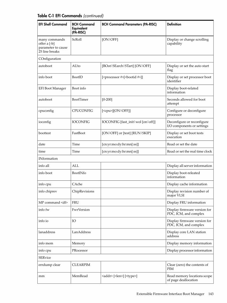
Table C-1 EFI Commands (continued)
DefinitionBCH Command Parameters (PA-RISC)BCH CommandEquivalent(PA-RISC)
EFI Shell Command
Display or change scrollingcapability
[ON|OFF]ScRollmany commandsoffer a [-b]parameter to cause25 line breaks
COnfiguration
Display or set the auto startflag
[BOot|SEarch|STart] [ON|OFF]AUtoautoboot
Display or set processor bootidentifier
[<processor #>[<bootid #>]]BootIDinfo boot
Display boot-relatedinformation
Boot infoEFI Boot Manager
Seconds allowed for bootattempt
[0-200]BootTimerautoboot
Configure or deconfigureprocessor
[<cpu>][ON|OFF]]CPUCONFIGcpuconfig
Deconfigure or reconfigureI/O components or settings
IOCONFIG [fast_init|wol [on|off]]IOCONFIGioconfig
Display or set boot testsexecution
[ON|OFF] or [test] [RUN|SKIP]FastBootboottest
Read or set the date[cn:yr:mo:dy:hr:mn[:ss]]Timedate
Read or set the real time clock[cn:yr:mo:dy:hr:mn[:ss]]Timetime
INformation
Display all server informationALLinfo all
Display boot-releatedinformation
BootINfoinfo boot
Display cache informationCAcheinfo cpu
Display revision number ofmajor VLSI
ChipRevisionsinfo chiprev
Display FRU informationFRUMP command <df>
Display firmware version forPDC, ICM, and complex
FwrVersioninfo fw
Display firmware version forPDC, ICM, and complex
IOinfo io
Display core LAN stationaddress
LanAddresslanaddress
Display memory informationMemoryinfo mem
Display processor informationPRocessorinfo cpu
SERvice
Clear (zero) the contents ofPIM
CLEARPIMerrdump clear
Read memory locations scopeof page deallocation
<addr> [<len>] [<type>]MemReadmm
Extensible Firmware Interface Boot Manager 143
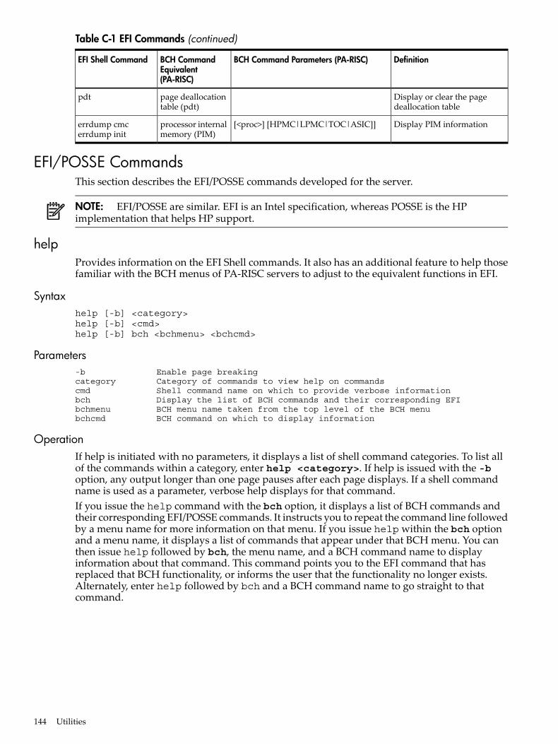
Table C-1 EFI Commands (continued)
DefinitionBCH Command Parameters (PA-RISC)BCH CommandEquivalent(PA-RISC)
EFI Shell Command
Display or clear the pagedeallocation table
page deallocationtable (pdt)
pdt
Display PIM information[<proc>] [HPMC|LPMC|TOC|ASIC]]processor internalmemory (PIM)
errdump cmcerrdump init
EFI/POSSE CommandsThis section describes the EFI/POSSE commands developed for the server.
NOTE: EFI/POSSE are similar. EFI is an Intel specification, whereas POSSE is the HPimplementation that helps HP support.
helpProvides information on the EFI Shell commands. It also has an additional feature to help thosefamiliar with the BCH menus of PA-RISC servers to adjust to the equivalent functions in EFI.
Syntaxhelp [-b] <category>help [-b] <cmd>help [-b] bch <bchmenu> <bchcmd>
Parameters-b Enable page breakingcategory Category of commands to view help on commandscmd Shell command name on which to provide verbose informationbch Display the list of BCH commands and their corresponding EFI bchmenu BCH menu name taken from the top level of the BCH menubchcmd BCH command on which to display information
OperationIf help is initiated with no parameters, it displays a list of shell command categories. To list allof the commands within a category, enter help <category>. If help is issued with the -boption, any output longer than one page pauses after each page displays. If a shell commandname is used as a parameter, verbose help displays for that command.If you issue the help command with the bch option, it displays a list of BCH commands andtheir corresponding EFI/POSSE commands. It instructs you to repeat the command line followedby a menu name for more information on that menu. If you issue help within the bch optionand a menu name, it displays a list of commands that appear under that BCH menu. You canthen issue help followed by bch, the menu name, and a BCH command name to displayinformation about that command. This command points you to the EFI command that hasreplaced that BCH functionality, or informs the user that the functionality no longer exists.Alternately, enter help followed by bch and a BCH command name to go straight to thatcommand.
144 Utilities
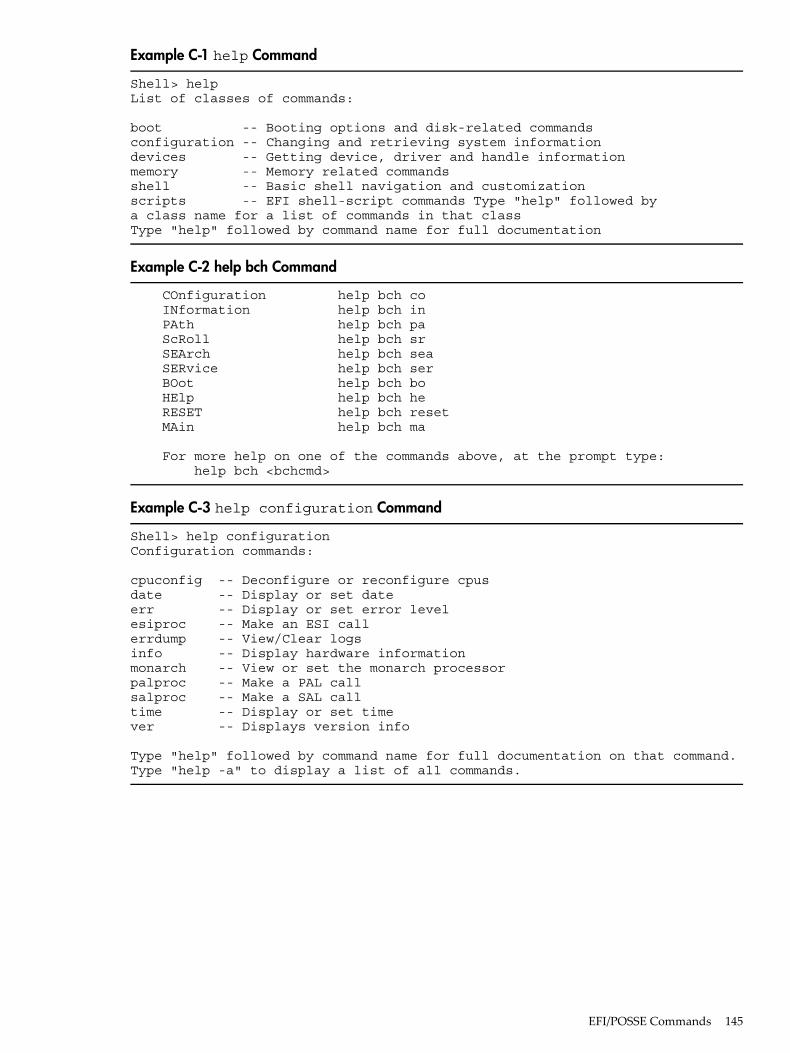
Example C-1 help Command
Shell> helpList of classes of commands:
boot -- Booting options and disk-related commandsconfiguration -- Changing and retrieving system informationdevices -- Getting device, driver and handle informationmemory -- Memory related commandsshell -- Basic shell navigation and customizationscripts -- EFI shell-script commands Type "help" followed by a class name for a list of commands in that classType "help" followed by command name for full documentation
Example C-2 help bch Command
COnfiguration help bch co INformation help bch in PAth help bch pa ScRoll help bch sr SEArch help bch sea SERvice help bch ser BOot help bch bo HElp help bch he RESET help bch reset MAin help bch ma
For more help on one of the commands above, at the prompt type: help bch <bchcmd>
Example C-3 help configuration Command
Shell> help configurationConfiguration commands:
cpuconfig -- Deconfigure or reconfigure cpusdate -- Display or set dateerr -- Display or set error levelesiproc -- Make an ESI callerrdump -- View/Clear logsinfo -- Display hardware informationmonarch -- View or set the monarch processorpalproc -- Make a PAL callsalproc -- Make a SAL calltime -- Display or set timever -- Displays version info
Type "help" followed by command name for full documentation on that command.Type "help -a" to display a list of all commands.
EFI/POSSE Commands 145
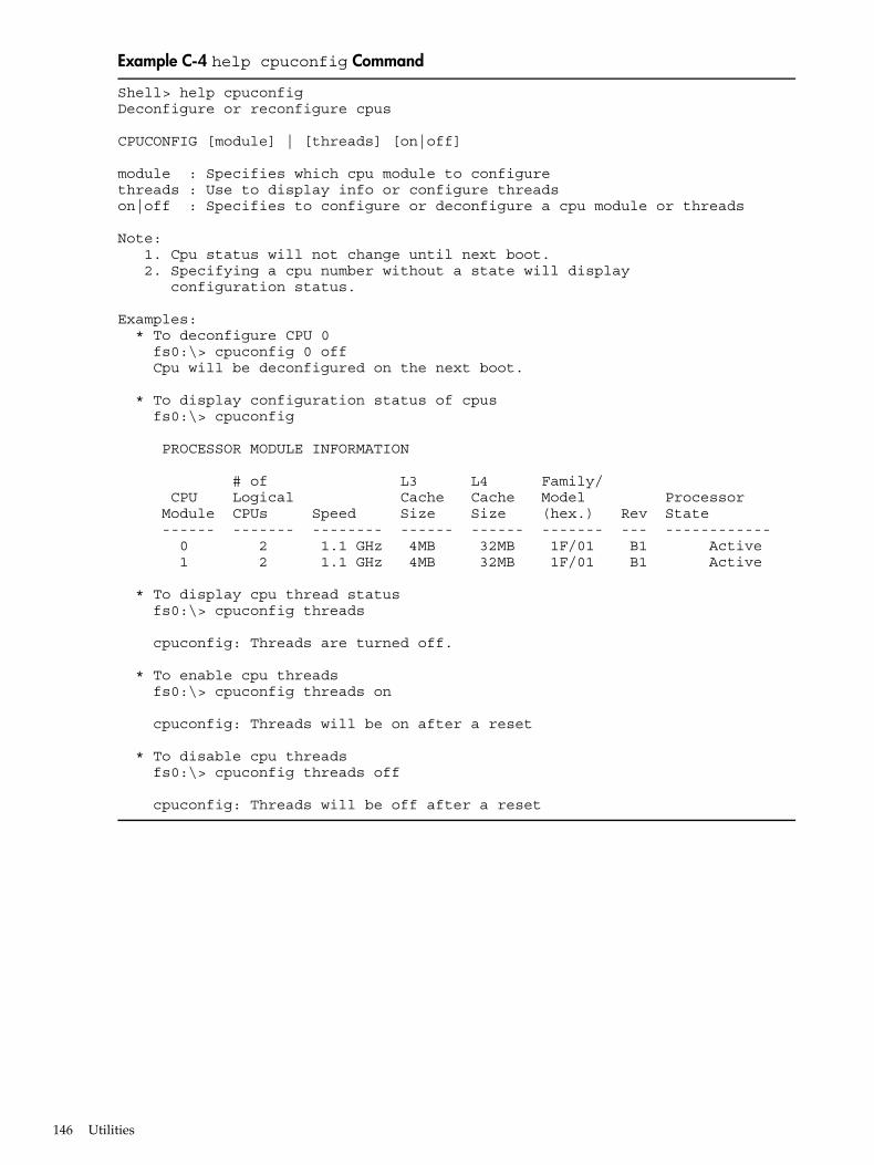
Example C-4 help cpuconfig Command
Shell> help cpuconfigDeconfigure or reconfigure cpus
CPUCONFIG [module] | [threads] [on|off]
module : Specifies which cpu module to configurethreads : Use to display info or configure threadson|off : Specifies to configure or deconfigure a cpu module or threads
Note: 1. Cpu status will not change until next boot. 2. Specifying a cpu number without a state will display configuration status.
Examples: * To deconfigure CPU 0 fs0:\> cpuconfig 0 off Cpu will be deconfigured on the next boot.
* To display configuration status of cpus fs0:\> cpuconfig
PROCESSOR MODULE INFORMATION
# of L3 L4 Family/ CPU Logical Cache Cache Model Processor Module CPUs Speed Size Size (hex.) Rev State ------ ------- -------- ------ ------ ------- --- ------------ 0 2 1.1 GHz 4MB 32MB 1F/01 B1 Active 1 2 1.1 GHz 4MB 32MB 1F/01 B1 Active
* To display cpu thread status fs0:\> cpuconfig threads
cpuconfig: Threads are turned off.
* To enable cpu threads fs0:\> cpuconfig threads on
cpuconfig: Threads will be on after a reset
* To disable cpu threads fs0:\> cpuconfig threads off
cpuconfig: Threads will be off after a reset
146 Utilities
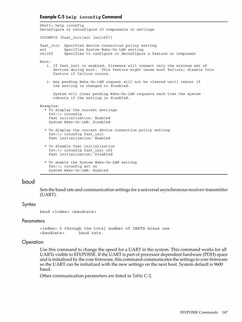
Example C-5 help ioconfig Command
Shell> help ioconfigDeconfigure or reconfigure IO components or settings
IOCONFIG [fast_init|wol [on|off]]
fast_init Specifies device connection policy settingwol Specifies System Wake-On-LAN settingon|off Specifies to configure or deconfigure a feature or component
Note: 1. If fast_init is enabled, firmware will connect only the minimum set of devices during boot. This feature might cause boot failure; disable this feature if failure occurs.
2. Any pending Wake-On-LAN request will not be cleared until reboot if the setting is changed to disabled.
System will clear pending Wake-On-LAN requests each time the system reboots if the setting is disabled.
Examples: * To display the current settings fs0:\> ioconfig Fast initialization: Enabled System Wake-On-LAN: Disabled
* To display the current device connection policy setting fs0:\> ioconfig fast_init Fast initialization: Enabled
* To disable fast initialization fs0:\> ioconfig fast_init off Fast initialization: Disabled
* To enable the System Wake-On-LAN setting fs0:\> ioconfig wol on System Wake-On-LAN: Enabled
baudSets the baud rate and communication settings for a universal asynchronous receiver-transmitter(UART).
Syntaxbaud <index> <baudrate>
Parameters<index> 0 through the total number of UARTS minus one<baudrate> baud rate.
OperationUse this command to change the speed for a UART in the system. This command works for allUARTs visible to EFI/POSSE. If the UART is part of processor dependent hardware (PDH) spaceand is initialized by the core firmware, this command communicates the settings to core firmwareso the UART can be initialized with the new settings on the next boot. System default is 9600baud.Other communication parameters are listed in Table C-2.
EFI/POSSE Commands 147

Table C-2 Communications Parameters
ValueParameter
1RECEIVE_FIFO_DEPTH
1000000TIMEOUT
No parityPARITY
8DATA_BITS
1STOP_BITS
0CONTROL_MASK
boottestInteracts with the speedy boot variable allowing it to be set appropriately.
Syntaxboottest Displays status of all speedy boot bitsboottest on Run all tests (for a normal boot time)boottest off Skip all tests (for a faster boot time)boottest [test] Displays status of specific Speedy Boot bitboottest [test] [on|off] Sets or clears a specific Speedy Boot bit
Parameters[test] Each test can be set or cleared: booting_valid Enable/disable system firmware response to BOOTING bit. If OS Speedy Boot aware set to on. early_cpu Enable/disable early CPU selftests. late_cpu Enable/disable late CPU selftests. platform Enable/disable system board hardware tests. chipset Enable/disable CEC tests. io_hw Enable/disable EFI driver Core I/O tests. mem_init Enable/disable memory initialization. mem_test Enable/disable full destructive memory tests.
148 Utilities

Example C-6 boottest Command
Shell> boottest BOOTTEST Settings Default Variable Selftest Setting ------------- ------------------------- booting_valid On (OS speedy boot aware) early_cpu Run this test late_cpu Run this test platform Run this test chipset Run this test io_hw Run this test mem_init Run this test mem_test Run this test
Example C-7 boottest early_cpu off Command
Shell> boottest early_cpu off BOOTTEST Settings Default Variable Selftest Setting ------------- ------------------------- booting_valid On (OS speedy boot aware) early_cpu Skip this test late_cpu Run this test platform Run this test chipset Run this test io_hw Run this test mem_init Run this test mem_test Run this test
cpuconfigDisplays the configured or deconfigured state of processors in the system and enables you toconfigure or reconfigure processors.
Syntaxcpuconfig <cpu> <on|off>
Parameters<cpu> specify a processor<on|off> state to set the processor to
OperationIssuing cpuconfig with no parameters displays the config/deconfig status of all processors. Toreconfigure CPUs, specify a CPU number and a state on or off. If a valid state is entered and isdifferent from the current state of a CPU, its status changes on the next boot.
EFI/POSSE Commands 149

NOTE: The last remaining configured CPU in a server cannot be deconfigured.
Example C-8 cpuconfig Command
Shell> cpuconfigPROCESSOR INFORMATION
Proc Arch Processor CPU Speed Rev Model Family Rev State--- ------- --------- ------- ----- ------ ----- 0 1.6Ghz B1 0 31 0 Sched Deconf 1 1.6Ghz B1 0 31 0 Active
ioconfigDeconfigures or reconfigures I/O components or settings.
Syntaxioconfig <fast_init | wol> <on|off>
Parameters<fast_init> specify device connection policy setting<wol> specify system wake-on-lan setting <on|off> specify to configure or deconfigure a feature or component
OperationThe ioconfig file retains information on the server I/O configuration across reboots. Theioconfig file is created by insf at installation time, and is modified by insf, rmsf, andioscan when devices are added or removed. The ioconfig file maintains configurationinformation when the system is not running.
150 Utilities

Example C-9 ioconfig Command
Shell> ioconfigDeconfigure or reconfigure IO components or settings
IOCONFIG [fast_init|wol [on|off]]
fast_init Specifies device connection policy settingwol Specifies System Wake-On-LAN settingon|off Specifies to configure or deconfigure a feature or component
Note: 1. If fast_init is enabled, firmware will connect only the minimum set of devices during boot. This feature might cause boot failure; disable this feature if failure occurs.
2. Any pending Wake-On-LAN request will not be cleared until reboot if the setting is changed to disabled.
System will clear pending Wake-On-LAN requests each time the system reboots if the setting is disabled.
Examples: * To display the current settings fs0:\> ioconfig Fast initialization: Enabled System Wake-On-LAN: Disabled
* To display the current device connection policy setting fs0:\> ioconfig fast_init Fast initialization: Enabled
* To disable fast initialization fs0:\> ioconfig fast_init off Fast initialization: Disabled
* To enable the System Wake-On-LAN setting fs0:\> ioconfig wol on System Wake-On-LAN: Enabled
conconfigConfigures the primary console and turns on other consoles for mirroring from the firmware.
Syntaxconconfig [index][on|off|primary]
ParametersIndex Specifies index of console to set as primaryon Enables the specified console as a secondary consoleoff Puts console into "Not Configured" (NC) stateprimary Sets the specified console as primary
Notes• Primary console setting will take effect after reboot.• P in the status column indicates that the console is the primary.• S in the status column indicates that the console is the secondary.• NC in the status column indicates that the console is not configured.• If a disabled console is set to primary, it is enabled.
EFI/POSSE Commands 151
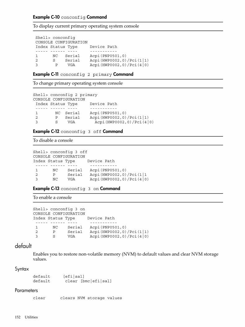
Example C-10 conconfig Command
To display current primary operating system console
Shell> conconfig CONSOLE CONFIGURATION Index Status Type Device Path ----- ------ ---- ----------- 1 NC Serial Acpi(PNP0501,0) 2 S Serial Acpi(HWP0002,0)/Pci(1|1) 3 P VGA Acpi(HWP0002,0)/Pci(4|0)
Example C-11 conconfig 2 primary Command
To change primary operating system console
Shell> conconfig 2 primaryCONSOLE CONFIGURATION Index Status Type Device Path ----- ------ ---- ----------- 1 NC Serial Acpi(PNP0501,0) 2 P Serial Acpi(HWP0002,0)/Pci(1|1) 3 S VGA Acpi(HWP0002,0)/Pci(4|0)
Example C-12 conconfig 3 off Command
To disable a console
Shell> conconfig 3 offCONSOLE CONFIGURATIONIndex Status Type Device Path ----- ------ ---- ----------- 1 NC Serial Acpi(PNP0501,0) 2 P Serial Acpi(HWP0002,0)/Pci(1|1 3 NC VGA Acpi(HWP0002,0)/Pci(4|0)
Example C-13 conconfig 3 on Command
To enable a console
Shell> conconfig 3 onCONSOLE CONFIGURATIONIndex Status Type Device Path ----- ------ ---- ----------- 1 NC Serial Acpi(PNP0501,0) 2 P Serial Acpi(HWP0002,0)/Pci(1|1) 3 S VGA Acpi(HWP0002,0)/Pci(4|0)
defaultEnables you to restore non-volatile memory (NVM) to default values and clear NVM storagevalues.
Syntaxdefault [efi|sal]default clear [bmc|efi|sal]
Parametersclear clears NVM storage values
152 Utilities
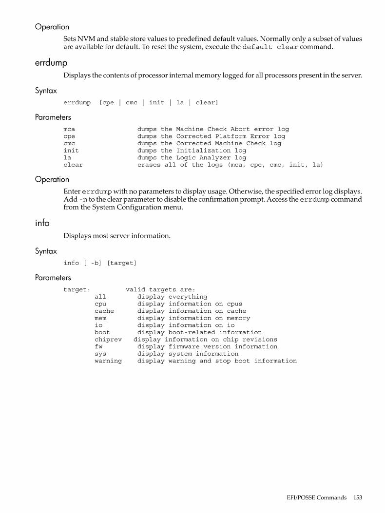
OperationSets NVM and stable store values to predefined default values. Normally only a subset of valuesare available for default. To reset the system, execute the default clear command.
errdumpDisplays the contents of processor internal memory logged for all processors present in the server.
Syntaxerrdump [cpe | cmc | init | la | clear]
Parametersmca dumps the Machine Check Abort error logcpe dumps the Corrected Platform Error logcmc dumps the Corrected Machine Check loginit dumps the Initialization logla dumps the Logic Analyzer logclear erases all of the logs (mca, cpe, cmc, init, la)
OperationEnter errdumpwith no parameters to display usage. Otherwise, the specified error log displays.Add-n to the clear parameter to disable the confirmation prompt. Access theerrdump commandfrom the System Configuration menu.
infoDisplays most server information.
Syntaxinfo [ -b] [target]
Parameterstarget: valid targets are: all display everything cpu display information on cpus cache display information on cache mem display information on memory io display information on io boot display boot-related information chiprev display information on chip revisions fw display firmware version information sys display system information warning display warning and stop boot information
EFI/POSSE Commands 153
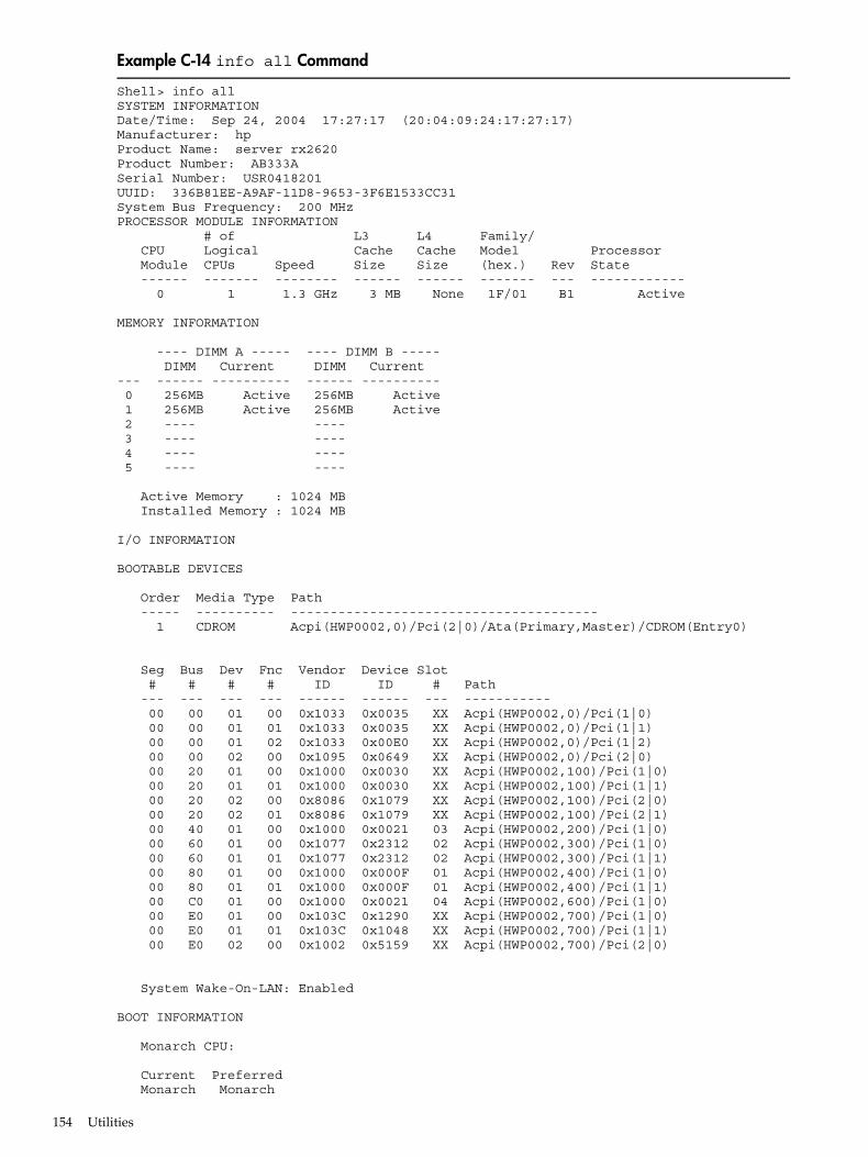
Example C-14 info all Command
Shell> info allSYSTEM INFORMATIONDate/Time: Sep 24, 2004 17:27:17 (20:04:09:24:17:27:17)Manufacturer: hpProduct Name: server rx2620 Product Number: AB333ASerial Number: USR0418201 UUID: 336B81EE-A9AF-11D8-9653-3F6E1533CC31System Bus Frequency: 200 MHzPROCESSOR MODULE INFORMATION # of L3 L4 Family/ CPU Logical Cache Cache Model Processor Module CPUs Speed Size Size (hex.) Rev State ------ ------- -------- ------ ------ ------- --- ------------ 0 1 1.3 GHz 3 MB None 1F/01 B1 Active
MEMORY INFORMATION
---- DIMM A ----- ---- DIMM B ----- DIMM Current DIMM Current --- ------ ---------- ------ ---------- 0 256MB Active 256MB Active 1 256MB Active 256MB Active 2 ---- ---- 3 ---- ---- 4 ---- ---- 5 ---- ----
Active Memory : 1024 MB Installed Memory : 1024 MB
I/O INFORMATION
BOOTABLE DEVICES
Order Media Type Path ----- ---------- --------------------------------------- 1 CDROM Acpi(HWP0002,0)/Pci(2|0)/Ata(Primary,Master)/CDROM(Entry0)
Seg Bus Dev Fnc Vendor Device Slot # # # # ID ID # Path --- --- --- --- ------ ------ --- ----------- 00 00 01 00 0x1033 0x0035 XX Acpi(HWP0002,0)/Pci(1|0) 00 00 01 01 0x1033 0x0035 XX Acpi(HWP0002,0)/Pci(1|1) 00 00 01 02 0x1033 0x00E0 XX Acpi(HWP0002,0)/Pci(1|2) 00 00 02 00 0x1095 0x0649 XX Acpi(HWP0002,0)/Pci(2|0) 00 20 01 00 0x1000 0x0030 XX Acpi(HWP0002,100)/Pci(1|0) 00 20 01 01 0x1000 0x0030 XX Acpi(HWP0002,100)/Pci(1|1) 00 20 02 00 0x8086 0x1079 XX Acpi(HWP0002,100)/Pci(2|0) 00 20 02 01 0x8086 0x1079 XX Acpi(HWP0002,100)/Pci(2|1) 00 40 01 00 0x1000 0x0021 03 Acpi(HWP0002,200)/Pci(1|0) 00 60 01 00 0x1077 0x2312 02 Acpi(HWP0002,300)/Pci(1|0) 00 60 01 01 0x1077 0x2312 02 Acpi(HWP0002,300)/Pci(1|1) 00 80 01 00 0x1000 0x000F 01 Acpi(HWP0002,400)/Pci(1|0) 00 80 01 01 0x1000 0x000F 01 Acpi(HWP0002,400)/Pci(1|1) 00 C0 01 00 0x1000 0x0021 04 Acpi(HWP0002,600)/Pci(1|0) 00 E0 01 00 0x103C 0x1290 XX Acpi(HWP0002,700)/Pci(1|0) 00 E0 01 01 0x103C 0x1048 XX Acpi(HWP0002,700)/Pci(1|1) 00 E0 02 00 0x1002 0x5159 XX Acpi(HWP0002,700)/Pci(2|0)
System Wake-On-LAN: Enabled
BOOT INFORMATION
Monarch CPU:
Current Preferred Monarch Monarch
154 Utilities

CPU CPU Module/ Module/ Logical Logical Warnings ------- --------- -------- 0/0 0/0
AutoBoot: ON - Timeout is : 10 sec
Boottest:
BOOTTEST Settings Default Variable
OS is not speedy boot aware.
Selftest Setting --------- -------------- early_cpu Run this test late_cpu Run this test platform Run this test chipset Run this test io_hw Run this test mem_init Run this test mem_test Run this test
LAN Address Information:
LAN Address Path ----------------- ---------------------------------------- *Mac(000E7F7E07FA) Acpi(HWP0002,100)/Pci(2|0)/Mac(000E7F7E07FA)) Mac(000E7F7E07FB) Acpi(HWP0002,100)/Pci(2|1)/Mac(000E7F7E07FB))
FIRMWARE INFORMATION
Firmware Revision: 86.10 [4432] PAL_A: 7.31/5.37 PAL_B: 5.69 EFI Spec: 1.10 EFI Intel Drop: 14.62 EFI Build: 86.10 SAL Spec: 3.01 SAL_A: 2.00 SAL_B: 86.10 POSSE: 0.10 ACPI: 7.00 SMBIOS: 2.3.2a:
BMC Revision: 3.42 IPMI: 1.00 Management Processor Revision: E.03.02 Updatable EFI Drivers:
************ 2nd part **********************
Seg Bus Dev Fnc Vendor Device Slot # # # # ID ID # Path --- --- --- --- ------ ------ --- ----------- 00 00 01 00 0x1033 0x0035 XX Acpi(HWP0002,0)/Pci(1|0) 00 00 01 01 0x1033 0x0035 XX Acpi(HWP0002,0)/Pci(1|1) 00 00 01 02 0x1033 0x00E0 XX Acpi(HWP0002,0)/Pci(1|2) 00 00 02 00 0x1095 0x0649 XX Acpi(HWP0002,0)/Pci(2|0) 00 20 01 00 0x1000 0x0030 XX Acpi(HWP0002,100)/Pci(1|0) 00 20 01 01 0x1000 0x0030 XX Acpi(HWP0002,100)/Pci(1|1) 00 20 02 00 0x8086 0x1079 XX Acpi(HWP0002,100)/Pci(2|0) 00 20 02 01 0x8086 0x1079 XX Acpi(HWP0002,100)/Pci(2|1) 00 40 01 00 0x1000 0x0021 03 Acpi(HWP0002,200)/Pci(1|0) 00 60 01 00 0x1077 0x2312 02 Acpi(HWP0002,300)/Pci(1|0) 00 60 01 01 0x1077 0x2312 02 Acpi(HWP0002,300)/Pci(1|1) 00 80 01 00 0x1000 0x000F 01 Acpi(HWP0002,400)/Pci(1|0) 00 80 01 01 0x1000 0x000F 01 Acpi(HWP0002,400)/Pci(1|1) 00 C0 01 00 0x1000 0x0021 04 Acpi(HWP0002,600)/Pci(1|0) 00 E0 01 00 0x103C 0x1290 XX Acpi(HWP0002,700)/Pci(1|0) 00 E0 01 01 0x103C 0x1048 XX Acpi(HWP0002,700)/Pci(1|1)
EFI/POSSE Commands 155
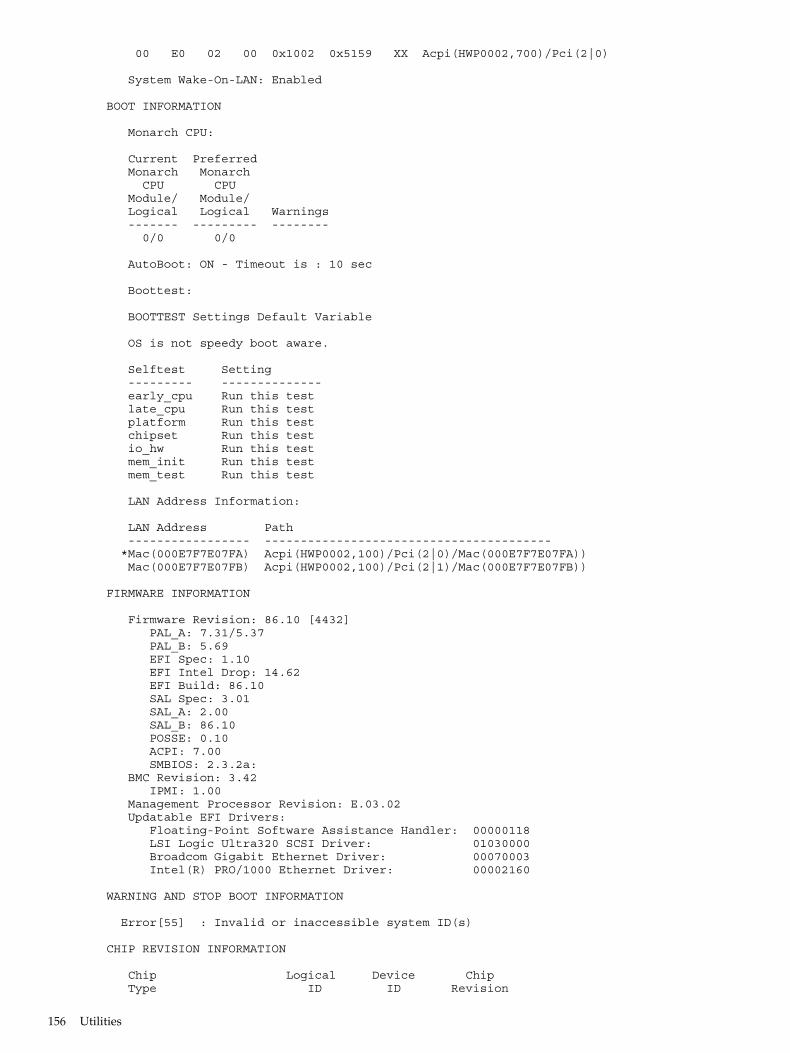
00 E0 02 00 0x1002 0x5159 XX Acpi(HWP0002,700)/Pci(2|0)
System Wake-On-LAN: Enabled
BOOT INFORMATION
Monarch CPU:
Current Preferred Monarch Monarch CPU CPU Module/ Module/ Logical Logical Warnings ------- --------- -------- 0/0 0/0
AutoBoot: ON - Timeout is : 10 sec
Boottest:
BOOTTEST Settings Default Variable
OS is not speedy boot aware.
Selftest Setting --------- -------------- early_cpu Run this test late_cpu Run this test platform Run this test chipset Run this test io_hw Run this test mem_init Run this test mem_test Run this test
LAN Address Information:
LAN Address Path ----------------- ---------------------------------------- *Mac(000E7F7E07FA) Acpi(HWP0002,100)/Pci(2|0)/Mac(000E7F7E07FA)) Mac(000E7F7E07FB) Acpi(HWP0002,100)/Pci(2|1)/Mac(000E7F7E07FB))
FIRMWARE INFORMATION
Firmware Revision: 86.10 [4432] PAL_A: 7.31/5.37 PAL_B: 5.69 EFI Spec: 1.10 EFI Intel Drop: 14.62 EFI Build: 86.10 SAL Spec: 3.01 SAL_A: 2.00 SAL_B: 86.10 POSSE: 0.10 ACPI: 7.00 SMBIOS: 2.3.2a: BMC Revision: 3.42 IPMI: 1.00 Management Processor Revision: E.03.02 Updatable EFI Drivers: Floating-Point Software Assistance Handler: 00000118 LSI Logic Ultra320 SCSI Driver: 01030000 Broadcom Gigabit Ethernet Driver: 00070003 Intel(R) PRO/1000 Ethernet Driver: 00002160
WARNING AND STOP BOOT INFORMATION
Error[55] : Invalid or inaccessible system ID(s)
CHIP REVISION INFORMATION
Chip Logical Device Chip Type ID ID Revision
156 Utilities
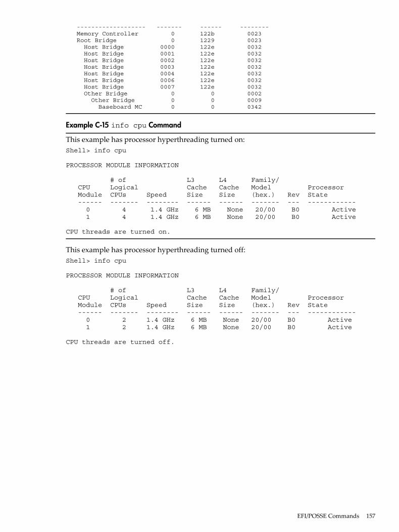
------------------- ------- ------ -------- Memory Controller 0 122b 0023 Root Bridge 0 1229 0023 Host Bridge 0000 122e 0032 Host Bridge 0001 122e 0032 Host Bridge 0002 122e 0032 Host Bridge 0003 122e 0032 Host Bridge 0004 122e 0032 Host Bridge 0006 122e 0032 Host Bridge 0007 122e 0032 Other Bridge 0 0 0002 Other Bridge 0 0 0009 Baseboard MC 0 0 0342
Example C-15 info cpu Command
This example has processor hyperthreading turned on:Shell> info cpu
PROCESSOR MODULE INFORMATION
# of L3 L4 Family/ CPU Logical Cache Cache Model Processor Module CPUs Speed Size Size (hex.) Rev State ------ ------- -------- ------ ------ ------- --- ------------ 0 4 1.4 GHz 6 MB None 20/00 B0 Active 1 4 1.4 GHz 6 MB None 20/00 B0 Active
CPU threads are turned on.
This example has processor hyperthreading turned off:Shell> info cpu
PROCESSOR MODULE INFORMATION
# of L3 L4 Family/ CPU Logical Cache Cache Model Processor Module CPUs Speed Size Size (hex.) Rev State ------ ------- -------- ------ ------ ------- --- ------------ 0 2 1.4 GHz 6 MB None 20/00 B0 Active 1 2 1.4 GHz 6 MB None 20/00 B0 Active
CPU threads are turned off.
EFI/POSSE Commands 157

Example C-16 info mem Command
Shell> info mem
MEMORY INFORMATION
---- DIMM A ----- ---- DIMM B ----- DIMM Current DIMM Current --- ------ ---------- ------ ---------- 0 256MB Active 256MB Active 1 256MB Active 256MB Active 2 ---- ---- 3 ---- ---- 4 ---- ---- 5 ---- ----
Active Memory : 1024 MB Installed Memory : 1024 MB
Example C-17 info io Command
Shell> info io
I/O INFORMATION
BOOTABLE DEVICES
Order Media Type Path ----- ---------- --------------------------------------- 1 CDROM Acpi(HWP0002,0)/Pci(2|0)/Ata(Primary,Master)/CDROM(Entry0)
Seg Bus Dev Fnc Vendor Device Slot # # # # ID ID # Path --- --- --- --- ------ ------ --- ----------- 00 00 01 00 0x1033 0x0035 XX Acpi(HWP0002,0)/Pci(1|0) 00 00 01 01 0x1033 0x0035 XX Acpi(HWP0002,0)/Pci(1|1) 00 00 01 02 0x1033 0x00E0 XX Acpi(HWP0002,0)/Pci(1|2) 00 00 02 00 0x1095 0x0649 XX Acpi(HWP0002,0)/Pci(2|0) 00 20 01 00 0x1000 0x0030 XX Acpi(HWP0002,100)/Pci(1|0) 00 20 01 01 0x1000 0x0030 XX Acpi(HWP0002,100)/Pci(1|1) 00 20 02 00 0x8086 0x1079 XX Acpi(HWP0002,100)/Pci(2|0) 00 20 02 01 0x8086 0x1079 XX Acpi(HWP0002,100)/Pci(2|1) 00 40 01 00 0x1000 0x0021 03 Acpi(HWP0002,200)/Pci(1|0) 00 60 01 00 0x1077 0x2312 02 Acpi(HWP0002,300)/Pci(1|0) 00 60 01 01 0x1077 0x2312 02 Acpi(HWP0002,300)/Pci(1|1) 00 80 01 00 0x1000 0x000F 01 Acpi(HWP0002,400)/Pci(1|0) 00 80 01 01 0x1000 0x000F 01 Acpi(HWP0002,400)/Pci(1|1) 00 C0 01 00 0x1000 0x0021 04 Acpi(HWP0002,600)/Pci(1|0) 00 E0 01 00 0x103C 0x1290 XX Acpi(HWP0002,700)/Pci(1|0) 00 E0 01 01 0x103C 0x1048 XX Acpi(HWP0002,700)/Pci(1|1) 00 E0 02 00 0x1002 0x5159 XX Acpi(HWP0002,700)/Pci(2|0) System Wake-On-LAN: Enabled
158 Utilities
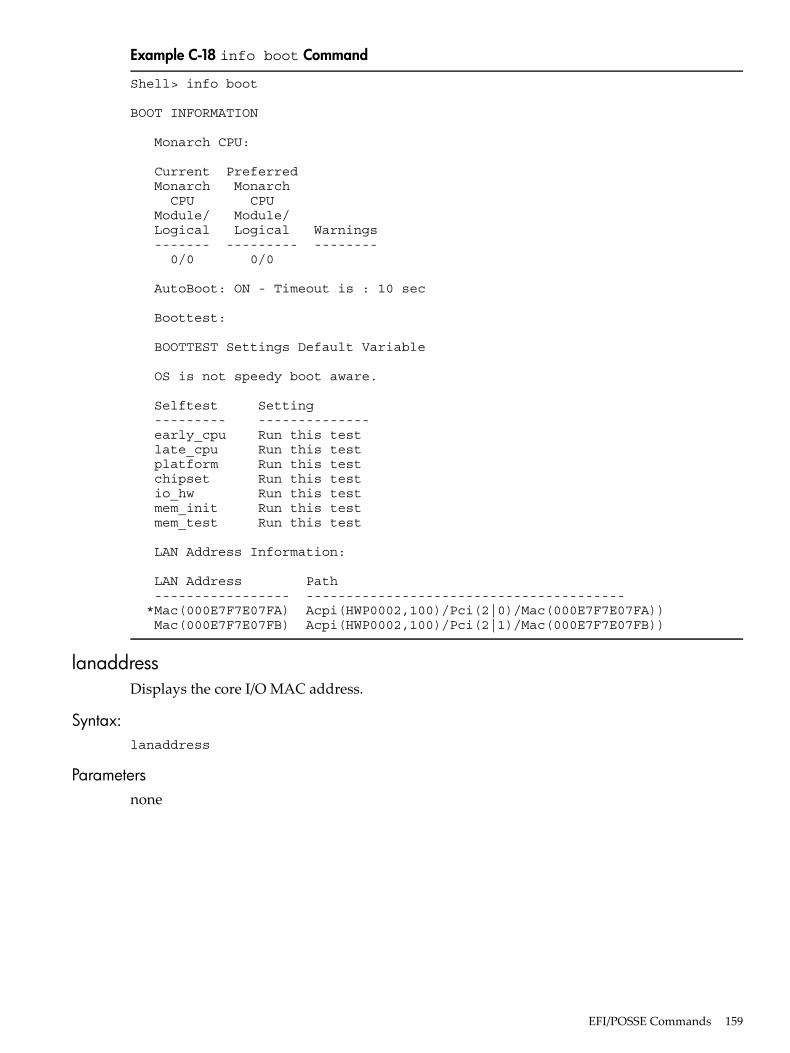
Example C-18 info boot Command
Shell> info boot
BOOT INFORMATION
Monarch CPU:
Current Preferred Monarch Monarch CPU CPU Module/ Module/ Logical Logical Warnings ------- --------- -------- 0/0 0/0
AutoBoot: ON - Timeout is : 10 sec
Boottest:
BOOTTEST Settings Default Variable
OS is not speedy boot aware.
Selftest Setting --------- -------------- early_cpu Run this test late_cpu Run this test platform Run this test chipset Run this test io_hw Run this test mem_init Run this test mem_test Run this test
LAN Address Information:
LAN Address Path ----------------- ---------------------------------------- *Mac(000E7F7E07FA) Acpi(HWP0002,100)/Pci(2|0)/Mac(000E7F7E07FA)) Mac(000E7F7E07FB) Acpi(HWP0002,100)/Pci(2|1)/Mac(000E7F7E07FB))
lanaddressDisplays the core I/O MAC address.
Syntax:lanaddress
Parametersnone
EFI/POSSE Commands 159
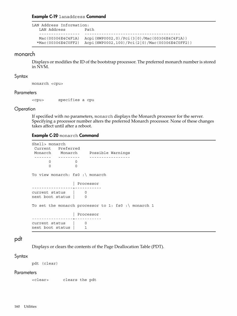
Example C-19 lanaddress Command
LAN Address Information: LAN Address Path ----------------- ---------------------------------------- Mac(00306E4C4F1A) Acpi(HWP0002,0)/Pci(3|0)/Mac(00306E4C4F1A)) *Mac(00306E4C0FF2) Acpi(HWP0002,100)/Pci(2|0)/Mac(00306E4C0FF2))
monarchDisplays or modifies the ID of the bootstrap processor. The preferred monarch number is storedin NVM.
Syntaxmonarch <cpu>
Parameters<cpu> specifies a cpu
OperationIf specified with no parameters, monarch displays the Monarch processor for the server.Specifying a processor number alters the preferred Monarch processor. None of these changestakes affect until after a reboot.
Example C-20 monarch Command
Shell> monarch Current Preferred Monarch Monarch Possible Warnings ------- --------- ----------------- 0 0 0 0
To view monarch: fs0 :\ monarch
| Processor-----------------+-----------current status | 0next boot status | 0
To set the monarch processor to 1: fs0 :\ monarch 1
| Processor-----------------+-----------current status | 0next boot status | 1
pdtDisplays or clears the contents of the Page Deallocation Table (PDT).
Syntaxpdt (clear)
Parameters<clear> clears the pdt
160 Utilities

OperationWith no options specified, the command displays the PDT information for the server. The PDTis cleared and a reboot is required for memory reallocation and safe booting.
Example C-21 pdt Command
Shell> pdtPDT Information for PD
Last Clear time for PD: PDT has not been cleared Number of total entries in PD PDT: 100 Number of used entries in PD PDT: 0 Number of free entries in PD PDT: 50 Number of permanent correctable (SBE) entries in PD PDT: 0 Number of permanent uncorrectable (MBE) entries in PD PDT: 0 Address of first uncorrectable error in PD: 0x0000000000000000
Example C-22 pdt clear Command
Shell> pdt clearAre you sure you want to clear the PDT? [y/N] yShell>
Shell> pdtPDT Information
Last Clear time: 10/21/01 5:00p Number of total entries in PDT: 50 Number of used entries in PDT: 0 Number of free entries in PDT: 50 Number of single-bit entries in PDT: 0 Number of multi-bit entries in PDT: 0 Address of first multi-bit error: 0x0000000000000000
sysmodeDisplays or modifies the system mode.
Syntaxsysmode <normal | admin| service>
Parameters<normal> sets system mode to normal
<admin> sets system mode to admin
<service> sets system mode to service
OperationIf specified alone, sysmode displays the system mode. If a mode is specified as a parameter, thesystem mode changes immediately. The system mode is retained on successive boots.
EFI/POSSE Commands 161

Example C-23 sysmode Command
Shell> sysmodeSystem Mode: NORMAL
Shell> sysmode adminYou are now in admin mode.
Shell> sysmode serviceYou are now in service mode.
Shell> sysmode normalYou are now in normal mode.
Specifying SCSI ParametersThe following SCSI parameters can be configured for the SCSI board:• SCSI ID (SCSI initiator ID)• Maximum data transfer rate (SCSI rate)• Bus width• Whether the HBA is bootable (driver support)• Avoid bus resets (secondary cluster server)
Using the SCSI Setup UtilityTo use the SCSI Setup Utility to specify SCSI parameters:
162 Utilities
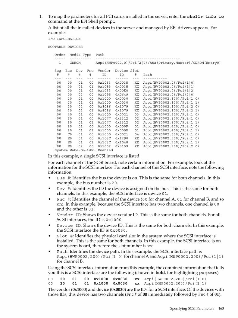
1. To map the parameters for all PCI cards installed in the server, enter the shell> info iocommand at the EFI Shell prompt.A list of all the installed devices in the server and managed by EFI drivers appears. Forexample:I/O INFORMATION
BOOTABLE DEVICES
Order Media Type Path ----- ---------- --------------------------------------- 1 CDROM Acpi(HWP0002,0)/Pci(2|0)/Ata(Primary,Master)/CDROM(Entry0)
Seg Bus Dev Fnc Vendor Device Slot # # # # ID ID # Path --- --- --- --- ------ ------ --- ----------- 00 00 01 00 0x1033 0x0035 XX Acpi(HWP0002,0)/Pci(1|0) 00 00 01 01 0x1033 0x0035 XX Acpi(HWP0002,0)/Pci(1|1) 00 00 01 02 0x1033 0x00E0 XX Acpi(HWP0002,0)/Pci(1|2) 00 00 02 00 0x1095 0x0649 XX Acpi(HWP0002,0)/Pci(2|0) 00 20 01 00 0x1000 0x0030 XX Acpi(HWP0002,100)/Pci(1|0) 00 20 01 01 0x1000 0x0030 XX Acpi(HWP0002,100)/Pci(1|1) 00 20 02 00 0x8086 0x1079 XX Acpi(HWP0002,100)/Pci(2|0) 00 20 02 01 0x8086 0x1079 XX Acpi(HWP0002,100)/Pci(2|1) 00 40 01 00 0x1000 0x0021 03 Acpi(HWP0002,200)/Pci(1|0) 00 60 01 00 0x1077 0x2312 02 Acpi(HWP0002,300)/Pci(1|0) 00 60 01 01 0x1077 0x2312 02 Acpi(HWP0002,300)/Pci(1|1) 00 80 01 00 0x1000 0x000F 01 Acpi(HWP0002,400)/Pci(1|0) 00 80 01 01 0x1000 0x000F 01 Acpi(HWP0002,400)/Pci(1|1) 00 C0 01 00 0x1000 0x0021 04 Acpi(HWP0002,600)/Pci(1|0) 00 E0 01 00 0x103C 0x1290 XX Acpi(HWP0002,700)/Pci(1|0) 00 E0 01 01 0x103C 0x1048 XX Acpi(HWP0002,700)/Pci(1|1) 00 E0 02 00 0x1002 0x5159 XX Acpi(HWP0002,700)/Pci(2|0) System Wake-On-LAN: Enabled
In this example, a single SCSI interface is listed.For each channel of the SCSI board, note certain information. For example, look at theinformation for the SCSI interface. For each channel of this SCSI interface, note the followinginformation:• Bus #: Identifies the bus the device is on. This is the same for both channels. In this
example, the bus number is 20.• Dev #: Identifies the ID the device is assigned on the bus. This is the same for both
channels. In this example, the SCSI interface is device 01.• Fnc #: Identifies the channel of the device (00 for channel A, 01 for channel B, and so
on). In this example, because the SCSI interface has two channels, one channel is 00and the other is 01.
• Vendor ID: Shows the device vendor ID. This is the same for both channels. For allSCSI interfaces, the ID is 0x1000.
• Device ID: Shows the device ID. This is the same for both channels. In this example,the SCSI interface the ID is 0x0030.
• Slot #: Identifies the physical card slot in the system where the SCSI interface isinstalled. This is the same for both channels. In this example, the SCSI interface is onthe system board, therefore the slot number is xx.
• Path: Identifies the device path. In this example, the SCSI interface path isAcpi(HWP0002,200)/Pci(1|0) for channel A andAcpi(HWP0002,200)/Pci(1|1)for channel B.
Using the SCSI interface information from this example, the combined information that tellsyou this is a SCSI interface are the following (shown in bold, for highlighting purposes):00 20 01 00 0x1000 0x0030 xx Acpi(HWP0002,200)/Pci(1|0)00 20 01 01 0x1000 0x0030 xx Acpi(HWP0002,200)/Pci(1|1)
The vendor (0x1000) and device (0x0030) are the IDs for a SCSI interface. Of the devices withthose IDs, this device has two channels (Fnc # of 00 immediately followed by Fnc # of 01).
Specifying SCSI Parameters 163
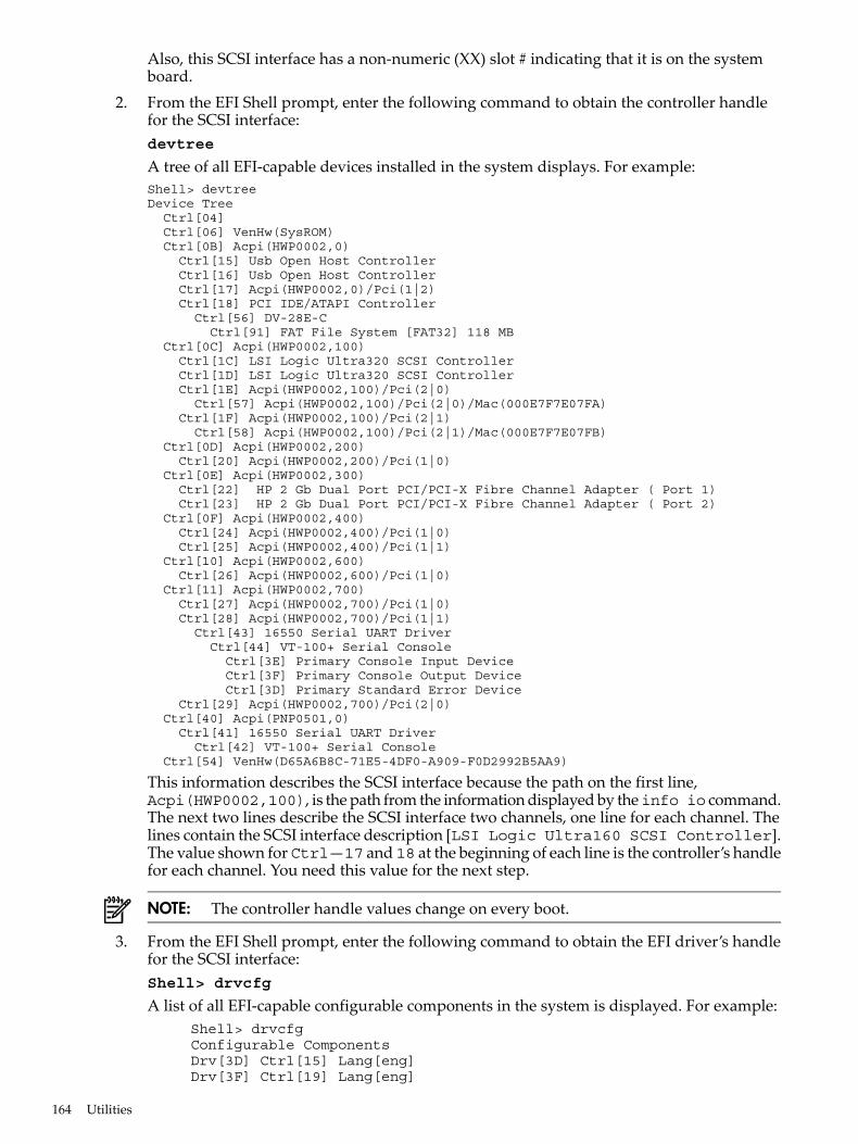
Also, this SCSI interface has a non-numeric (XX) slot # indicating that it is on the systemboard.
2. From the EFI Shell prompt, enter the following command to obtain the controller handlefor the SCSI interface:devtree
A tree of all EFI-capable devices installed in the system displays. For example:Shell> devtreeDevice Tree Ctrl[04] Ctrl[06] VenHw(SysROM) Ctrl[0B] Acpi(HWP0002,0) Ctrl[15] Usb Open Host Controller Ctrl[16] Usb Open Host Controller Ctrl[17] Acpi(HWP0002,0)/Pci(1|2) Ctrl[18] PCI IDE/ATAPI Controller Ctrl[56] DV-28E-C Ctrl[91] FAT File System [FAT32] 118 MB Ctrl[0C] Acpi(HWP0002,100) Ctrl[1C] LSI Logic Ultra320 SCSI Controller Ctrl[1D] LSI Logic Ultra320 SCSI Controller Ctrl[1E] Acpi(HWP0002,100)/Pci(2|0) Ctrl[57] Acpi(HWP0002,100)/Pci(2|0)/Mac(000E7F7E07FA) Ctrl[1F] Acpi(HWP0002,100)/Pci(2|1) Ctrl[58] Acpi(HWP0002,100)/Pci(2|1)/Mac(000E7F7E07FB) Ctrl[0D] Acpi(HWP0002,200) Ctrl[20] Acpi(HWP0002,200)/Pci(1|0) Ctrl[0E] Acpi(HWP0002,300) Ctrl[22] HP 2 Gb Dual Port PCI/PCI-X Fibre Channel Adapter ( Port 1) Ctrl[23] HP 2 Gb Dual Port PCI/PCI-X Fibre Channel Adapter ( Port 2) Ctrl[0F] Acpi(HWP0002,400) Ctrl[24] Acpi(HWP0002,400)/Pci(1|0) Ctrl[25] Acpi(HWP0002,400)/Pci(1|1) Ctrl[10] Acpi(HWP0002,600) Ctrl[26] Acpi(HWP0002,600)/Pci(1|0) Ctrl[11] Acpi(HWP0002,700) Ctrl[27] Acpi(HWP0002,700)/Pci(1|0) Ctrl[28] Acpi(HWP0002,700)/Pci(1|1) Ctrl[43] 16550 Serial UART Driver Ctrl[44] VT-100+ Serial Console Ctrl[3E] Primary Console Input Device Ctrl[3F] Primary Console Output Device Ctrl[3D] Primary Standard Error Device Ctrl[29] Acpi(HWP0002,700)/Pci(2|0) Ctrl[40] Acpi(PNP0501,0) Ctrl[41] 16550 Serial UART Driver Ctrl[42] VT-100+ Serial Console Ctrl[54] VenHw(D65A6B8C-71E5-4DF0-A909-F0D2992B5AA9)
This information describes the SCSI interface because the path on the first line,Acpi(HWP0002,100), is the path from the information displayed by theinfo io command.The next two lines describe the SCSI interface two channels, one line for each channel. Thelines contain the SCSI interface description [LSI Logic Ultra160 SCSI Controller].The value shown for Ctrl—17 and 18 at the beginning of each line is the controller’s handlefor each channel. You need this value for the next step.
NOTE: The controller handle values change on every boot.
3. From the EFI Shell prompt, enter the following command to obtain the EFI driver’s handlefor the SCSI interface:Shell> drvcfg
A list of all EFI-capable configurable components in the system is displayed. For example: Shell> drvcfg Configurable Components Drv[3D] Ctrl[15] Lang[eng] Drv[3F] Ctrl[19] Lang[eng]
164 Utilities
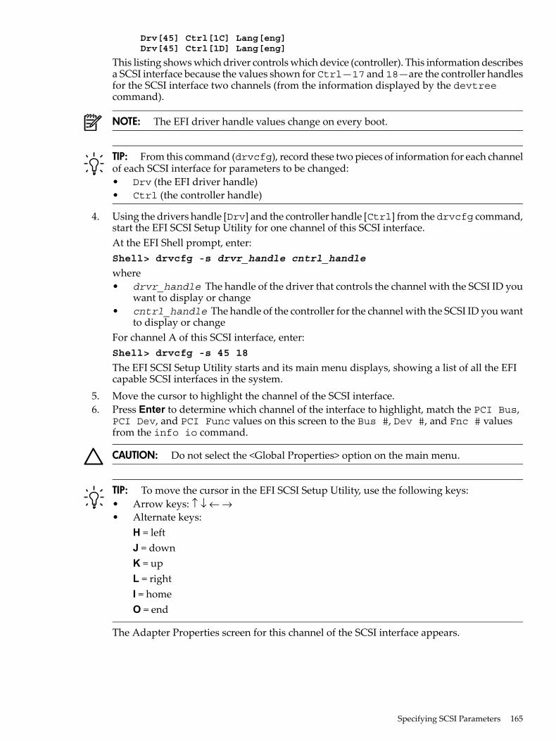
Drv[45] Ctrl[1C] Lang[eng] Drv[45] Ctrl[1D] Lang[eng]
This listing shows which driver controls which device (controller). This information describesa SCSI interface because the values shown for Ctrl—17 and 18—are the controller handlesfor the SCSI interface two channels (from the information displayed by the devtreecommand).
NOTE: The EFI driver handle values change on every boot.
TIP: From this command (drvcfg), record these two pieces of information for each channelof each SCSI interface for parameters to be changed:• Drv (the EFI driver handle)• Ctrl (the controller handle)
4. Using the drivers handle [Drv] and the controller handle [Ctrl] from thedrvcfg command,start the EFI SCSI Setup Utility for one channel of this SCSI interface.At the EFI Shell prompt, enter:Shell> drvcfg -s drvr_handle cntrl_handle
where• drvr_handle The handle of the driver that controls the channel with the SCSI ID you
want to display or change• cntrl_handle The handle of the controller for the channel with the SCSI ID you want
to display or changeFor channel A of this SCSI interface, enter:Shell> drvcfg -s 45 18
The EFI SCSI Setup Utility starts and its main menu displays, showing a list of all the EFIcapable SCSI interfaces in the system.
5. Move the cursor to highlight the channel of the SCSI interface.6. Press Enter to determine which channel of the interface to highlight, match the PCI Bus,
PCI Dev, and PCI Func values on this screen to the Bus #, Dev #, and Fnc # valuesfrom the info io command.
CAUTION: Do not select the <Global Properties> option on the main menu.
TIP: To move the cursor in the EFI SCSI Setup Utility, use the following keys:• Arrow keys: ↑ ↓ ← →• Alternate keys:
H = leftJ = downK = upL = rightI = homeO = end
The Adapter Properties screen for this channel of the SCSI interface appears.
Specifying SCSI Parameters 165

7. Be sure the utility is running for the channel of the SCSI interface by comparing the valuesshown for PCI Bus, PCI Device, and PCI Function to the Bus #, Dev #, and Fnc #values from the info io command.
CAUTION: Do not change the value for any of these fields on the Adapter Properties screen:• Auto Termination• SCSI Parity• SCSI Bus Scan Order• Spinup Delay (Secs)
Changing any of these fields can cause unpredictable results.
CAUTION: Do not change the value for any of these fields on the Device Properties screen:• Scan Id• Scan LUNs > 0• Disconnect• SCSI Timeout• Queue Tags• Format• Verify
Changing any of these fields can cause unpredictable results.
8. Display the SCSI parameters listed below for the channel of the SCSI interface and changethe parameters if necessary, or restore the SCSI parameters to their default values.• SCSI ID• Maximum data transfer rate• Bus width• Whether the SCSI interface is bootable (driver support)• Avoid bus resets (secondary cluster server)• Restore defaults
9. Use the arrow keys to navigate to the appropriate SCSI parameter.10. Use the plus (+) and minus (-) keys to scroll through the values until the value you want
displays.11. Press Esc to exit the Adapter Properties screen.12. Move the cursor to the action (cancel, save, or discard) you want to take, and press
Enter.13. Select one of the following options:
• Cancel the exit to stay on the Adapter Properties screen for the channel of the SCSIinterface.
• Save the changes you made, then exit the screen.• Discard the changes you made, then exit the screen.If you select cancel, you remain in the Adapter Properties screen for the channel of theSCSI interface. You can still change the channel parameters.If you select save or discard, the EFI SCSI Setup Utility main menu appears.
CAUTION: Do not select the <Global Properties> option on the main menu.
14. Press Esc to exit the main menu and the EFI SCSI Setup Utility.15. Select the option for exiting the utility.16. When you are prompted, press Enter to stop the SCSI interface; you are now at the EFI Shell
prompt.17. At the EFI Shell prompt, enter Shell> reset.
The system starts to reboot. This sets the new SCSI setting.
166 Utilities

Using the Boot Option Maintenance MenuThis menu enables you to select console output and input devices as well as various boot options.The menu items are described below.The following selections are available on all menus:• Help: Displays the help available for the command.• Exit: Returns to the main Boot Options Maintenance menu.• Enter: Selects an item after using the arrow keys to highlight the item.• Save Settings to NVRAM: Saves your changes.
NOTE: The options shown here are examples. Your server might have different options availablebased on the server configuration and installed hardware components.
PathsAll devices in servers are represented by paths in the EFI Shell. To identify the correct slot ordisk drive, use the following tables.
Table C-3 Server Sockets
PathSocket
Acpi(HWP0002,400)/pci(1|0)1 PCI
Acpi(HWP0002,300)/pci(1|0)2 PCI
Acpi(HWP0002,200)/pci(1|0)3 PCI
Acpi(HWP0002,600)/pci(1|0)4 PCI
Table C-4 Server Drives
PathDrive
Acpi(HWP0002,100)/Pci(1|1)/Scsi(Pun2,Lun0)SCSI Disk (HDD1)
Acpi(HWP0002,100)/Pci(1|0)/Scsi(Pun1,Lun0)SCSI Disk (HDD2)
Acpi(HWP0002,100)/Pci(1|0)/Scsi(Pun0,Lun0)SCSI Disk (HDD3)
Acpi(HWP0002,0)/Pci(2|0)/ATARemovable Media Boot
Boot From FileUse this option to manually run a specific application or driver.
NOTE: This option boots the selected application or driver one time only. When you exit theapplication, you return to this menu.
This option displays the file systems that are on your server or workstation and lets you browsethese file systems for applications or drivers that are executable. Executable files end with the.efi extension. You can also select remote boot (LAN) options that have been configured onyour network.For example:Boot From a File. Select a Volume NO VOLUME LABEL [Acpi(HWP0002,0)/Pci(2|0)/Ata(Primary,Master)/CDROM CD_FORMAT [Acpi(HWP0002,0)/Pci(2|0)/Ata(Secondary,Master)/CDROM Removable Media Boot [Acpi(HWP0002,500)/Pci(2|0)/Ata(Secondary,Master) Load File [EFI Shell [Built-in]] Load File [Acpi(HWP0002,0)/Pci(3|0)/Mac(00306E4C4F1A)] Exit
Using the Boot Option Maintenance Menu 167
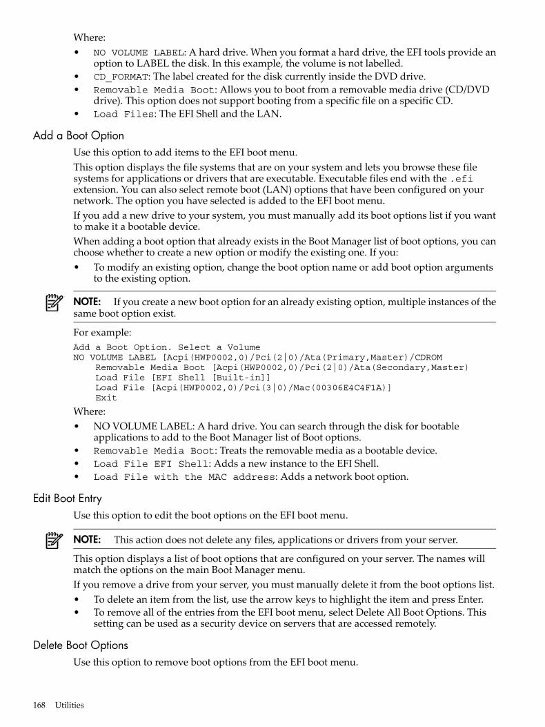
Where:• NO VOLUME LABEL: A hard drive. When you format a hard drive, the EFI tools provide an
option to LABEL the disk. In this example, the volume is not labelled.• CD_FORMAT: The label created for the disk currently inside the DVD drive.• Removable Media Boot: Allows you to boot from a removable media drive (CD/DVD
drive). This option does not support booting from a specific file on a specific CD.• Load Files: The EFI Shell and the LAN.
Add a Boot OptionUse this option to add items to the EFI boot menu.This option displays the file systems that are on your system and lets you browse these filesystems for applications or drivers that are executable. Executable files end with the .efiextension. You can also select remote boot (LAN) options that have been configured on yournetwork. The option you have selected is added to the EFI boot menu.If you add a new drive to your system, you must manually add its boot options list if you wantto make it a bootable device.When adding a boot option that already exists in the Boot Manager list of boot options, you canchoose whether to create a new option or modify the existing one. If you:• To modify an existing option, change the boot option name or add boot option arguments
to the existing option.
NOTE: If you create a new boot option for an already existing option, multiple instances of thesame boot option exist.
For example:Add a Boot Option. Select a VolumeNO VOLUME LABEL [Acpi(HWP0002,0)/Pci(2|0)/Ata(Primary,Master)/CDROM Removable Media Boot [Acpi(HWP0002,0)/Pci(2|0)/Ata(Secondary,Master) Load File [EFI Shell [Built-in]] Load File [Acpi(HWP0002,0)/Pci(3|0)/Mac(00306E4C4F1A)] Exit
Where:• NO VOLUME LABEL: A hard drive. You can search through the disk for bootable
applications to add to the Boot Manager list of Boot options.• Removable Media Boot: Treats the removable media as a bootable device.• Load File EFI Shell: Adds a new instance to the EFI Shell.• Load File with the MAC address: Adds a network boot option.
Edit Boot EntryUse this option to edit the boot options on the EFI boot menu.
NOTE: This action does not delete any files, applications or drivers from your server.
This option displays a list of boot options that are configured on your server. The names willmatch the options on the main Boot Manager menu.If you remove a drive from your server, you must manually delete it from the boot options list.• To delete an item from the list, use the arrow keys to highlight the item and press Enter.• To remove all of the entries from the EFI boot menu, select Delete All Boot Options. This
setting can be used as a security device on servers that are accessed remotely.
Delete Boot OptionsUse this option to remove boot options from the EFI boot menu.
168 Utilities

NOTE: This action does not delete any files, applications, or drivers from your system.
This option displays a list of boot options that are configured on the system. The names matchthe options on the main Boot Manager menu.If you remove a drive from the system, you must manually delete it from the boot options list.• To delete an item from the list, use the arrow keys to highlight the item and press Enter.• To remove all of the entries from the EFI Boot menu, select Delete All Boot Options. This
setting can be used as a security device on systems that are accessed remotely.
Change Boot OrderUse this option to remove boot options entry. The order in which options are listed in the EFIboot menu also reflects the order in which the server attempts to boot. If the first boot optionfails, the server tries booting the second, then the third, and so forth, until a boot option succeedsor until all options have failed.For example, if you normally boot using a configuration on your LAN but would like to bootfrom a local hard drive if the LAN is unavailable, move the LAN boot option to the top of thelist, followed by the hard drive boot option.The menu lists boot options that currently exist in the main Boot Manager menu. You can changethe priority of the items by moving them up or down in the list:• Press U to move an option up.• Press D to move an option down.• Select Save Settings to NVRAM to modify the order in the Boot Manager menu, which
modifies the order that the Boot Manager attempts to boot the options.• The items at the bottom of the screen (shown in bold in these examples) are descriptions of
the selected option.For example:Change boot order. Select an Operation EFI Shell [Built-in] Current OS Save Settings to NVRAM Help Exit
VenHw(D65A6B8C-71E5-4DF0-A909-F0D2992B5AA9) Boot0000
Manage BootNext SettingUse this option to run the selected boot option immediately upon entering the main Boot Managermenu. This option is useful for booting an option that only needs to be booted once, withoutchanging any other setting in the main Boot Manager menu. This operation occurs once and doesnot change the permanent system boot settings.This option displays the file systems that are on your system and lets you browse these filesystems for applications or drivers that are executable. Executable files end with the .efiextension. You can also select remote boot (LAN) options that have been configured on yournetwork.To restore the default BootNext setting, select Reset BootNext Setting.For example:Manage BootNext setting. Select an Operation EFI Shell [Built-in] Current OS Reset BootNext Setting Save Settings to NVRAM Help Exit
Using the Boot Option Maintenance Menu 169
VenHw(D65A6B8C-71E5-4DF0-A909-F0D2992B5AA9) Boot0000
Set AutoBoot TimeOutUse this option to set the amount of time the system pauses before it launches the first item inthe Boot Options list.For example:Set Auto Boot Timeout. Select an Option Set Timeout Value Delete/Disable Timeout Help Exit
Interrupting the timeout during the countdown stops the Boot Manager from loading any bootoptions automatically. If there is no countdown set, you must select boot options manually.• To set the auto boot timeout value, in seconds, select Set Timeout Value and enter the
desired value.• To disable the timeout function, select Delete/Disable Timeout.
NOTE: When this option is selected, the server does not automatically boot. The server stopsat the EFI boot menu and waits for user input.
Select Active Console Output DevicesUse this option to define the devices that display output from the system console. This list includesthe VGA monitor and a serial port for directing output to a terminal emulation package.
NOTE: If you install a modem in your server, make sure you disable the modem serial port inboth the Active Console Input and Active Console Output device lists.
NOTE: Some operating systems support multiple consoles, such as a simultaneous serial andVGA output. See your operating system documentation to determine how many consoles aresupported with your server. Multiple consoles are not supported for HP-UX or Windows (usethe Smart Setup CD to switch between COM A and iLO on Windows servers).
For example:Select the Console Output Device(s) Acpi(PNP0501,0)/Uart(9600 N81)/VenMsg(PcAnsi)Acpi(PNP0501,0)/Uart(9600 N81)/VenMsg(Vt100)* Acpi(PNP0501,0)/Uart(9600 N81)/VenMsg(Vt100+)Acpi(PNP0501,0)/Uart(9600 N81)/VenMsg(VtUtf8)Acpi(HWP0002,700)/Pci(1|1)/Uart(9600 N81)/VenMsg(PcAnsi)Acpi(HWP0002,700)/Pci(1|1)/Uart(9600 N81)/VenMsg(Vt100)* Acpi(HWP0002,700)/Pci(1|1)/Uart(9600 N81)/VenMsg(Vt100+)Acpi(HWP0002,700)/Pci(1|1)/Uart(9600 N81)/VenMsg(VtUtf8)* Acpi(HWP0002,700)/Pci(2|0)
* Indicates a currently selected device.This menu is identical to Console Error Devices. HP Integrity servers do not support differentconfigurations for Output and Error console. For correct operation:• When changes are made to either Output or Error console menus, the identical change must
be made in both menus.• When changing serial devices, changes must be made to Output, Input, and Error menus
for proper operation.
170 Utilities
Table C-5 Console Output Devices
Choose:To select:
Acpi(PNP0501,0)/Uart(9600 N81)/VenMsg(Vt100+)Serial A/Serial 1
Acpi(HWP0002,700)/Pci(1|1)/Uart(9600 N81)/VenMsg(Vt100+)iLO MP Serial Console
Acpi(HWP0002,700)/Pci(2|0)iLO MP VGA Port
• Each option is identified with an EFI device path. Not all options are available, dependingon the configuration of the server and the options purchased. Device paths can differ slightlyon different product models.
• On both serial device examples, UART 9600 indicates the current baud rate of the serialdevice (can be changed with the EFI Shell baud command), VenMsg Vt100+ is the currentemulation type (several different terminal emulation protocols are supported, see list above).
• Only one terminal emulation type (PcAnsi, Vt100, and so on) can be selected for each serialconsole, but multiple serial consoles can be selected at a time.
Select Active Console Input DevicesUse this option to define the devices that are used to provide input to the system console. Thislist normally includes the VGA monitor and a serial port for directing output to a terminalemulation package.
NOTE: If you install a modem in your server, make sure you disable the modem serial port inboth the Active Console Input and Active Console Output device lists.
NOTE: Some operating systems support multiple consoles, such as a simultaneous serial andVGA output. See your operating system documentation to determine how many consoles aresupported with your server. Multiple consoles are not supported for HP-UX or Windows (usethe Smart Setup CD to switch between COM A and iLO on Windows systems).
For example:Select the Console Output Device(s) Acpi(PNP0501,0)/Uart(9600 N81)/VenMsg(PcAnsi) Acpi(PNP0501,0)/Uart(9600 N81)/VenMsg(Vt100) * Acpi(PNP0501,0)/Uart(9600 N81)/VenMsg(Vt100+) Acpi(PNP0501,0)/Uart(9600 N81)/VenMsg(VtUtf8) Acpi(HWP0002,700)/Pci(1|1)/Uart(9600 N81)/VenMsg(PcAnsi) Acpi(HWP0002,700)/Pci(1|1)/Uart(9600 N81)/VenMsg(Vt100) * Acpi(HWP0002,700)/Pci(1|1)/Uart(9600 N81)/VenMsg(Vt100+) Acpi(HWP0002,700)/Pci(1|1)/Uart(9600 N81)/VenMsg(VtUtf8) * Acpi(HWP0002,700)/Pci(2|0)
* Indicates a currently selected device.This menu is identical to Console Error Devices. HP Integrity servers do not support differentconfigurations for Output and Error console. To ensure correct operation:• When you change either Output or Error console menus, you must make the identical
changes in both menus.• When changing serial devices, you must make changes to Output, Input, and Error menus.
Table C-6 Console Input Devices
ChooseTo select
Acpi(PNP0501,0)/Uart(9600 N81)/VenMsg(Vt100+)Serial A/Serial 1
Acpi(HWP0002,700)/Pci(1|1)/Uart(9600 N81)/VenMsg(Vt100+)iLO MP Serial Console
Acpi(HWP0002,700)/Pci(2|0)iLO MP VGA Port
Using the Boot Option Maintenance Menu 171
• Each option is identified with an EFI device path. Not all options are available, dependingon the configuration of the server and the options purchased. Device paths can differ slightlyon different product models.
• On both serial device examples, UART 9600 indicates the current baud rate of the serialdevice (can be changed with the EFI Shell baud command), VenMsg Vt100+ is the currentemulation type (several different terminal emulation protocols are supported).
• You can select only one terminal emulation type for each serial console, but you can selectmultiple serial consoles at a time.
Select Active Standard Error DevicesUse this option to define the devices that display error messages from the system console.This menu is identical to the Console Output Devices menu. The server does not support differentconfigurations for Output and Error console. When you make changes to either Output or Errorconsole menus, you must make the identical change in the other menu. When you change serialdevices, you must make changes to Output, Input, and Error menus for proper operation
Using the System Configuration MenuThe System Configuration menu on servers with EFI firmware version 2.0 or higher includes thefollowing options:• Security/Password Menu: Enables you to change the administrator and user passwords.• Advanced System Information Menu: Displays information about system and component
configuration.• Set System Date: Enables you to modify the system date.• Set System Time: Enables you to modify the system time.• Reset Configuration to Default: Enables you restore system settings to their original
configuration.• Help: Displays additional information about the available options.• Exit: Returns to the EFI startup menu.
Security/Password MenuEnables you to set administrator and user passwords to provide different levels of access to thesystem firmware.
Resetting PasswordsIf you forget your passwords, reset them by running using the iLO MP <Ctrl+N>rs command.This commando resets the iLO MP and resets the password.
NOTE: You can only run this command when directly connected to the server.
Advanced System InformationDisplays information about server and component configuration.
Set System TimeModifies the server time.
Set System DateModifies the server date.
Set User InterfaceChanges the legacy boot manager user interface.
172 Utilities
Set System Wake-On LANEnables or disables the server Wake-On_LAN settings.
Set System DefaultsSelects server default settings.
iLO MPThe Integrated Lights-Out management processor (iLO MP) for entry-level Integrity servers isan autonomous management subsystem embedded directly on the server. It is the foundationof the server’s High Availability (HA), embedded server, and fault management. It also providessystem administrators secure remote management capabilities regardless of server status orlocation. The iLO MP is available whenever the system is connected to a power source, even ifthe server main power switch is in the off position.HP has used several different names over the years to describe the management functionalityembedded in their servers, including “the management processor.” In addition, HP uses theterm “management processor” to refer to any embedded microprocessor that manages a system.Management processor is a descriptive term (such as “server”), and iLO, is a brand name, orlabel (such as “Integrity”).Remote access is the key to maximizing efficiency of administration and troubleshooting forenterprise servers. Integrity servers have been designed so all administrative functions that canbe performed locally on the machine, can also be performed remotely. iLO enables remote accessto the operating system console, control over the server power and hardware reset functionality,and works with the server to enable remote network booting through a variety of methods.For complete information on the iLO MP, see the HP Integrity and HP 9000 iLO Operations Guide.
iLO MP 173

174
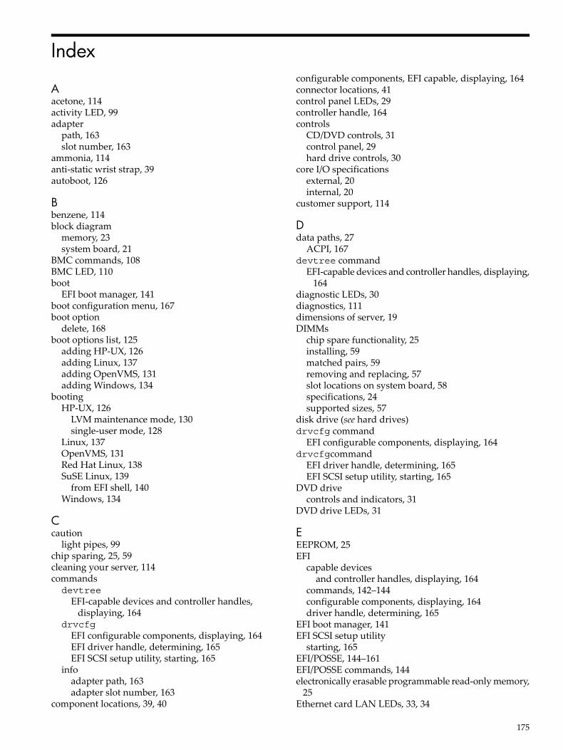
Index
Aacetone, 114activity LED, 99adapter
path, 163slot number, 163
ammonia, 114anti-static wrist strap, 39autoboot, 126
Bbenzene, 114block diagram
memory, 23system board, 21
BMC commands, 108BMC LED, 110boot
EFI boot manager, 141boot configuration menu, 167boot option
delete, 168boot options list, 125
adding HP-UX, 126adding Linux, 137adding OpenVMS, 131adding Windows, 134
bootingHP-UX, 126
LVM maintenance mode, 130single-user mode, 128
Linux, 137OpenVMS, 131Red Hat Linux, 138SuSE Linux, 139
from EFI shell, 140Windows, 134
Ccaution
light pipes, 99chip sparing, 25, 59cleaning your server, 114commandsdevtree
EFI-capable devices and controller handles,displaying, 164
drvcfgEFI configurable components, displaying, 164EFI driver handle, determining, 165EFI SCSI setup utility, starting, 165
infoadapter path, 163adapter slot number, 163
component locations, 39, 40
configurable components, EFI capable, displaying, 164connector locations, 41control panel LEDs, 29controller handle, 164controls
CD/DVD controls, 31control panel, 29hard drive controls, 30
core I/O specificationsexternal, 20internal, 20
customer support, 114
Ddata paths, 27
ACPI, 167devtree command
EFI-capable devices and controller handles, displaying,164
diagnostic LEDs, 30diagnostics, 111dimensions of server, 19DIMMs
chip spare functionality, 25installing, 59matched pairs, 59removing and replacing, 57slot locations on system board, 58specifications, 24supported sizes, 57
disk drive (see hard drives)drvcfg command
EFI configurable components, displaying, 164drvcfgcommand
EFI driver handle, determining, 165EFI SCSI setup utility, starting, 165
DVD drivecontrols and indicators, 31
DVD drive LEDs, 31
EEEPROM, 25EFI
capable devicesand controller handles, displaying, 164
commands, 142–144configurable components, displaying, 164driver handle, determining, 165
EFI boot manager, 141EFI SCSI setup utility
starting, 165EFI/POSSE, 144–161EFI/POSSE commands, 144electronically erasable programmable read-only memory,
25Ethernet card LAN LEDs, 33, 34
175
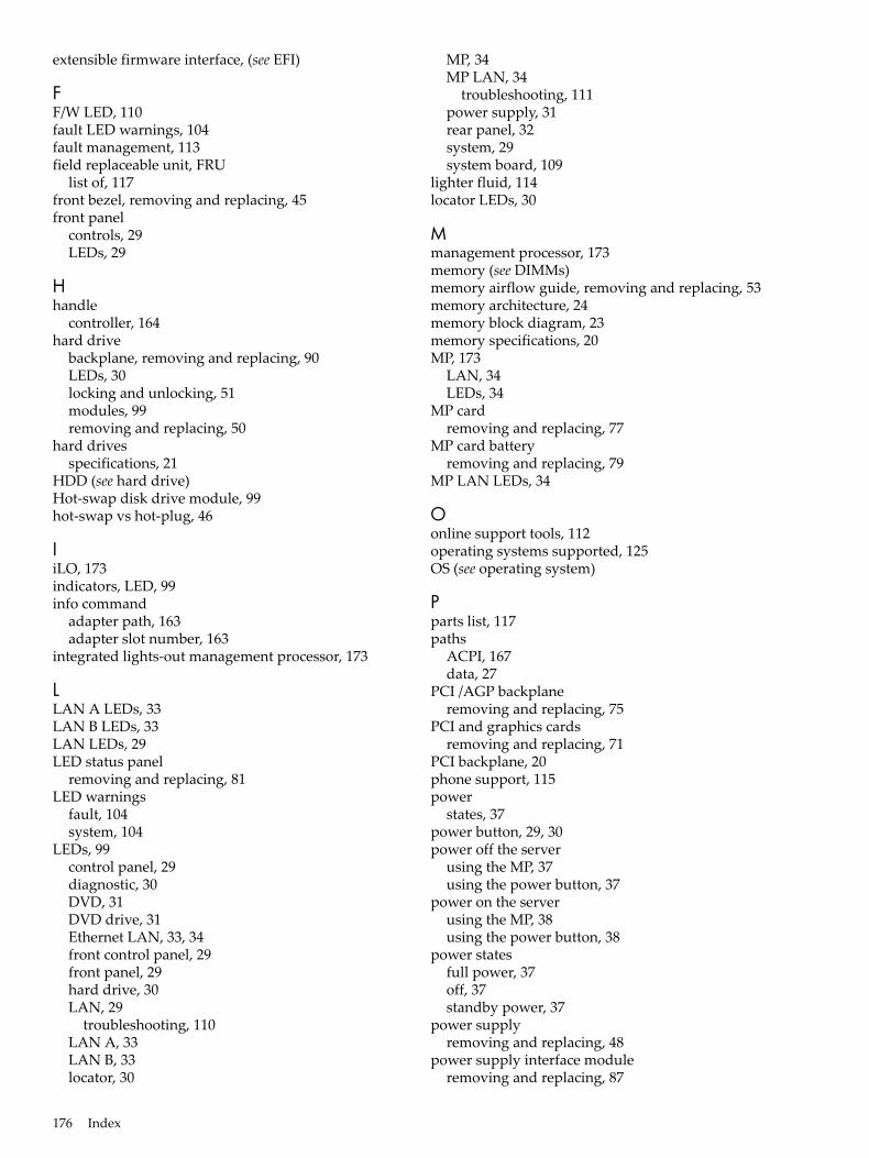
extensible firmware interface, (see EFI)
FF/W LED, 110fault LED warnings, 104fault management, 113field replaceable unit, FRU
list of, 117front bezel, removing and replacing, 45front panel
controls, 29LEDs, 29
Hhandle
controller, 164hard drive
backplane, removing and replacing, 90LEDs, 30locking and unlocking, 51modules, 99removing and replacing, 50
hard drivesspecifications, 21
HDD (see hard drive)Hot-swap disk drive module, 99hot-swap vs hot-plug, 46
IiLO, 173indicators, LED, 99info command
adapter path, 163adapter slot number, 163
integrated lights-out management processor, 173
LLAN A LEDs, 33LAN B LEDs, 33LAN LEDs, 29LED status panel
removing and replacing, 81LED warnings
fault, 104system, 104
LEDs, 99control panel, 29diagnostic, 30DVD, 31DVD drive, 31Ethernet LAN, 33, 34front control panel, 29front panel, 29hard drive, 30LAN, 29
troubleshooting, 110LAN A, 33LAN B, 33locator, 30
MP, 34MP LAN, 34
troubleshooting, 111power supply, 31rear panel, 32system, 29system board, 109
lighter fluid, 114locator LEDs, 30
Mmanagement processor, 173memory (see DIMMs)memory airflow guide, removing and replacing, 53memory architecture, 24memory block diagram, 23memory specifications, 20MP, 173
LAN, 34LEDs, 34
MP cardremoving and replacing, 77
MP card batteryremoving and replacing, 79
MP LAN LEDs, 34
Oonline support tools, 112operating systems supported, 125OS (see operating system)
Pparts list, 117paths
ACPI, 167data, 27
PCI /AGP backplaneremoving and replacing, 75
PCI and graphics cardsremoving and replacing, 71
PCI backplane, 20phone support, 115power
states, 37power button, 29, 30power off the server
using the MP, 37using the power button, 37
power on the serverusing the MP, 38using the power button, 38
power statesfull power, 37off, 37standby power, 37
power supplyremoving and replacing, 48
power supply interface moduleremoving and replacing, 87
176 Index

power supply LEDs, 31power supply, removing and replacing, 48Pre-OS System Environment (see EFI/POSSE)processor
location, 62socket specifications, 22specifications, 20
processor airflow guideremoving and replacing, 54
processor module, removing and replacing, 61
Rrear panel
LEDs, 32ports, 32
removable media driveremoving and replacing, 76
removing and replacingDIMMs, 57front bezel, 45hard drive, 50hard drive backplane, 90internal hard drive, 50LED status panel, 81memory airflow guide, 53MP card, 77MP card battery, 79PCI /AGP backplane, 75PCI and graphics cards, 71power supply, 48power supply interface module, 87processor airflow guide, 54processor module, 61removable media drive, 76system battery, 69system board, 82system covers and bezels, 42system fans, 46system memory, 57top metal cover, 43
Ssafety information, 39SCSI
setup utility, 162specifications, 20specifying parameters, 162
SCSI adapter path, 163SEL, 101server dimensions, 19server power states, 37server weight, 19service tools, 39shutting down
HP-UX, 130Linux, 140OpenVMS, 133Windows, 136, 137
STBY LED, 110
supportonline, 115phone, 114
supported operating systems, 125system battery
removing and replacing, 69system board
block diagram, 21components, 22connectors and slots, 40removing and replacing, 82
system board LEDs, 109system configuration menu, 172system covers and bezels
removing and replacing, 42system fans
removing and replacing, 46system fans, removing and replacing, 46system LED warnings, 104system LEDs, 29system memory
removing and replacing, 57
Ttools required, 39top metal cover, removing and replacing, 43trichlorethylene, 114
Uunlocking a hard drive, 51USB specifications, 27
Wweight of server, 19
177