hrust vector control s solid propellant de - … · thrust vector control system for solid...
TRANSCRIPT

THRUST VECTOR CONTROL SYSTEM FORSOLID PROPELLANT DE-ORBIT MOTORS
ESA CLEAN SPACE INDUSTRIAL DAYS 26 MAY 2016
IMAGE: ESA

THRUST VECTOR CONTROL SYSTEM FOR SOLID PROPELLANT DE-ORBIT MOTORS
PRESENTATION OUTLINE
1. Introduction A few words about Almatech
Project objectives
Baseline scenario
2. Conceptual design Identified design drivers
Concept tradeoff
Jet Flap Mechanism
Vectoring performance – SRM in space
3. Validation Cold flow testing
Test facility limitations
Validation of vectoring performance
Challenges of testing
4. Way forward Prospective way forward
2

• Integrated Systems
• Ultra-stable structures
• High precision mechanisms
• Thermo-optical hardware
THRUST VECTOR CONTROL SYSTEM FOR SOLID PROPELLANT DE-ORBIT MOTORS
ALMATECH IS A SPACE ENGINEERING COMPANY WITH ESTABLISHED
EXPERTISE IN FOUR MAIN FIELDS
Solar Orbiter
BepiColombo
ExoMars 2018
Sentinel-5
CHEOPSDETECTOR ELECTRONIC
MODULE (DEM) FORSOLAR ORBITER
OPTICAL TRAIN ASSEMBLY(OTA) FOR CHEOPS
OPTICAL STRUCTURE ANDRADIATORS (IOMSR) OF
SENTINEL-5
STIX WINDOWS FORSOLAR ORBITER
SLIT-CHANGE MECHANISM(SCM) FOR SOLAR
ORBITER
RECEIVER BAFFLE UNIT(RBU) FOR
BEPICOLOMBO
MLI OF THE CARRIERMODULE OF EXOMARS
2018
3

• Almatech was selected for the ESA Clean Space initiative to develop and test a Thrust Control
Vector (TVC) mechanism for de-orbiting purposes
(ESA Contract No. 4000112746/14/NL/KML )
• Almatech is Prime with 2 Italian partners:
Other project participants are:
• The objective of the activity is to
• identify vectoring solutions
• trade-off of vectoring concepts
• design
• manufacture and
• test a breadboard of a TVC mechanism
THRUST VECTOR CONTROL SYSTEM FOR SOLID PROPELLANT DE-ORBIT MOTORS
OBJECTIVES
TRP UNDER ESA CLEAN SPACE INITIATIVE
4

• Large spacecraft ~ 1500 kg
• LEO ~ 800 km altitude
• Rocket motor clustering 4 motors required for deorbit
• Rocket motor thrust level – 3 classes, nominal 250 N
• Long burning time ~ 4.75 min, cigarette burning
• Bell shaped nozzle
• High expansion ratio ~ 450
THRUST VECTOR CONTROL SYSTEM FOR SOLID PROPELLANT DE-ORBIT MOTORS
BASELINE SCENARIO
CHAMBER THROAT EXIT
𝐸𝐸𝐸𝐸𝐸𝐸𝐸𝐸𝐸𝐸𝐸𝐸𝐸𝐸𝐸𝐸𝐸𝐸 𝑟𝑟𝐸𝐸𝑟𝑟𝐸𝐸𝐸𝐸 =𝐴𝐴𝑟𝑟𝐴𝐴𝐸𝐸𝑒𝑒𝑒𝑒𝑒𝑒𝑒𝑒𝐴𝐴𝑟𝑟𝐴𝐴𝐸𝐸𝑒𝑒ℎ𝑟𝑟𝑟𝑟𝑟𝑟𝑒𝑒
5

THRUST VECTOR CONTROL SYSTEM FOR SOLID PROPELLANT DE-ORBIT MOTORS
IDENTIFIED DESIGN DRIVERS
Performance• thrust deflection angle > +/-5 deg
• thrust deflection rate > 10 deg/s
Cost-effectiveness• minimized complexity
• standardized components and processes
• manufacturing and assembly reproducibility
Reliability• non-operational lifetime of 15 years in-orbit
• long SRM burn time
Integration• interfaces
• ease of access and installation
• AIT activities
• cleanliness
Compactness• low mass, volume
• low encumbrance for clustering
6

THRUST VECTOR CONTROL SYSTEM FOR SOLID PROPELLANT DE-ORBIT MOTORS
CONCEPT TRADE-OFF
CO-FLOW CONCEPT
JET TAB IRIS MECHANISM
7
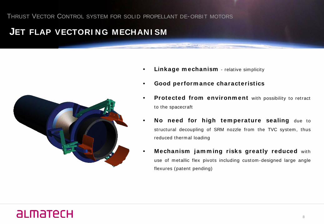
• Linkage mechanism - relative simplicity
• Good performance characteristics
• Protected from environment with possibility to retract
to the spacecraft
• No need for high temperature sealing due to
structural decoupling of SRM nozzle from the TVC system, thus
reduced thermal loading
• Mechanism jamming risks greatly reduced with
use of metallic flex pivots including custom-designed large angle
flexures (patent pending)
THRUST VECTOR CONTROL SYSTEM FOR SOLID PROPELLANT DE-ORBIT MOTORS
JET FLAP VECTORING MECHANISM
8

• Vectoring - 5 degree thrust
vectoring with 45 degree flap deflection
• Plume profile - under-expanded
• Exit pressure – 193 Pa
• Backflow is generated in axial gap
between nozzle exit plane and flap
• Flap deflector – curved following
the curvature of the nozzle exit,
providing a smooth continuation of the
nozzle to avoid generation of strong
shock waves
• Force on flaps – max. ~ 18 N
THRUST VECTOR CONTROL SYSTEM FOR SOLID PROPELLANT DE-ORBIT MOTORS
VECTORING PERFORMANCE – SRM IN SPACE
FLOW VELOCITY AND PRESSURE PROFILE AT 30 DEG FLAP DEFLECTION
CURVED FLAP PROFILE
9

• Cold gas testing in vacuum
• Facility:
• VKI Longshot Hypersonic Wind Tunnel Test Section
• Test chamber:
• diameter: 2.72 m, height: 3.25 m
• vacuum pump can go down to 1Pa
• Gas reservoir:
• 9800 liter
• maximum service pressure of 16 bars
• Working medium: N2
• Force balance test stand – installed in the chamber to
measure the trust intensity and direction
THRUST VECTOR CONTROL SYSTEM FOR SOLID PROPELLANT DE-ORBIT MOTORS
COLD FLOW TESTING
LONGSHOT HYPERSONICWIND TUNNEL TEST SECTION
10
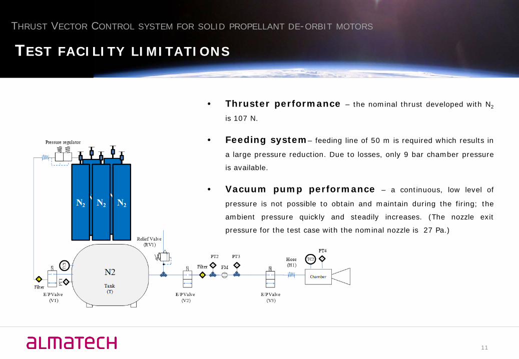
• Thruster performance – the nominal thrust developed with N2
is 107 N.
• Feeding system– feeding line of 50 m is required which results in
a large pressure reduction. Due to losses, only 9 bar chamber pressure
is available.
• Vacuum pump performance – a continuous, low level of
pressure is not possible to obtain and maintain during the firing; the
ambient pressure quickly and steadily increases. (The nozzle exit
pressure for the test case with the nominal nozzle is 27 Pa.)
THRUST VECTOR CONTROL SYSTEM FOR SOLID PROPELLANT DE-ORBIT MOTORS
TEST FACILITY LIMITATIONS
11

• Plume profile (Exit to ambient pressure ratio)- under-expansion can only be reproduced by significantly
decreasing the throat diameter, however forces on the flaps
become very low
• Chamber to exit pressure ratio – large due to very
large expansion ratio, challenging to reproduce
THRUST VECTOR CONTROL SYSTEM FOR SOLID PROPELLANT DE-ORBIT MOTORS
VALIDATION OF VECTORING PERFORMANCE
FLOW VELOCITY PROFILE AT 30 DEG FLAP DEFLECTIONMODEL WITH 65 PA AND 6500 PA AMBIENT PRESSURE
1
10
100
1000
1.E-05 1.E-04 1.E-03 1.E-02 1.E-01 1.E+00
Exp
an
sio
n r
ati
o
pe/pc
12

• Expansion ratio – can be changed by changing the throat diameter,
nozzle diameter or both
• Nozzle diameter – decreasing the diameter also shortens the nozzle
• Throat diameter - from a force measurement and manufacturing
point of view, it is advantageous to upscale the throat diameter; the larger
diameter, however, will results in a larger mass flow rate that will have
implications on the test time due to the limitations of the vacuum pump.
• Reynolds number - the Reynolds number is a function of the nozzle
exit diameter, thus the flow Reynolds number and BL thickness are not
reproduced when changing the nozzle geometry.
THRUST VECTOR CONTROL SYSTEM FOR SOLID PROPELLANT DE-ORBIT MOTORS
VALIDATION OF VECTORING PERFORMANCE – NOZZLE GEOMETRY
𝑑𝑑𝑒𝑒ℎ𝑟𝑟𝑟𝑟𝑟𝑟𝑒𝑒 = 9.17 𝑚𝑚𝑚𝑚
𝑑𝑑𝑛𝑛𝑟𝑟𝑛𝑛𝑛𝑛𝑛𝑛𝑒𝑒 = 196 𝑚𝑚𝑚𝑚
𝐸𝐸𝐸𝐸𝐸𝐸𝐸𝐸𝐸𝐸𝐸𝐸𝐸𝐸𝐸𝐸𝐸𝐸 𝑟𝑟𝐸𝐸𝑟𝑟𝐸𝐸𝐸𝐸 = 450
13

• Hypersonic similarity - a Mach number of 4.88 is required from the cold flow model
(SRM exit Mach number: 6).
THRUST VECTOR CONTROL SYSTEM FOR SOLID PROPELLANT DE-ORBIT MOTORS
VALIDATION OF VECTORING PERFORMANCE
40 60 80 100 120 140100
1 103×
1 104×
1 105×
1 106×
1 107×
3
4
5
6
exit pressure (Tc=298K, pc=9bar, gam=1.4)exit pressure (Tc=298K, pc=15bar, gam=1.4)N2 vapor pressure curveMax Mach number as a function of Te exhausting to vac (Tc=298K)
Exit temperature (K)
Pres
sure
(Pa)
Max
. Mac
h nu
mbe
r
• Nitrogen can condense in a hypersonic nozzle due to the expansion of
the flow. This phenomenon is can significantly affect the accuracy of the
experiments.
• For the matched Mach number (4.88) condensation will likely occur, as
it the corresponding exit temperature is 51 K.
• To avoid condensation:
1) an exit temperature of 100 K is chosen. The required Mach
number is 3.146 No hypersonic similarity
2) the combustion chamber needs to be heated to ~580 K. No
cold flow
14
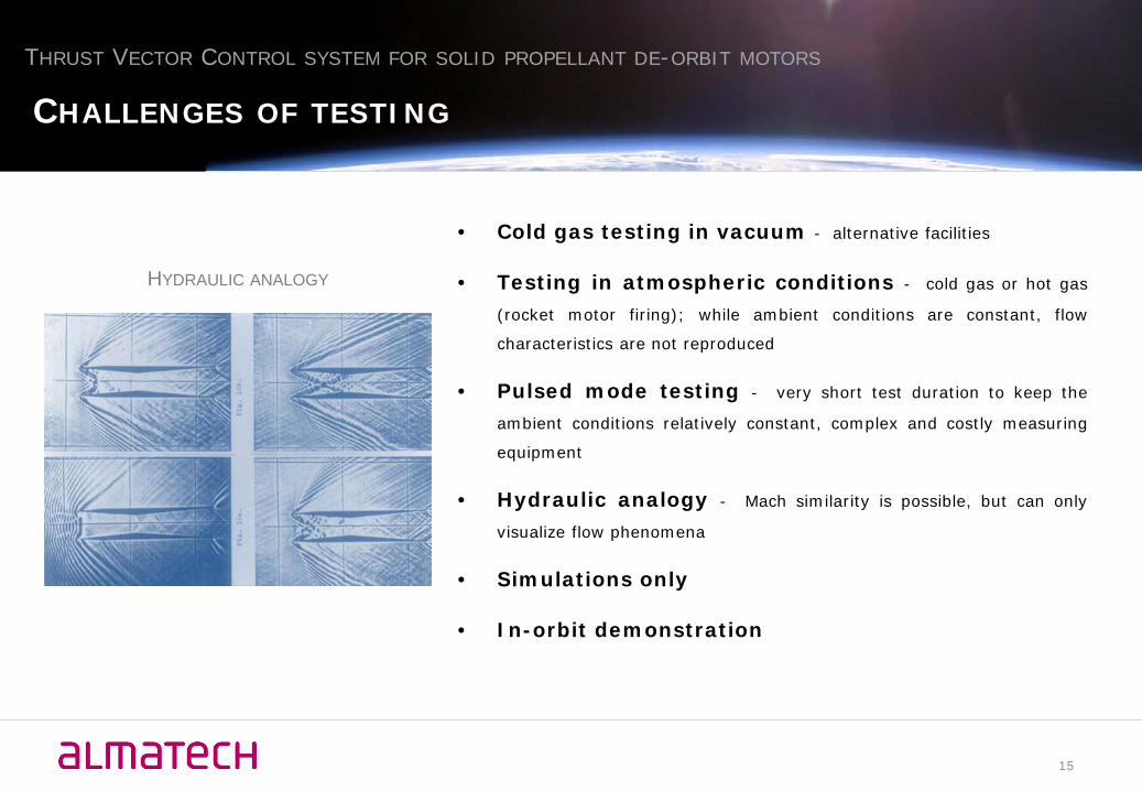
• Cold gas testing in vacuum - alternative facilities
• Testing in atmospheric conditions - cold gas or hot gas
(rocket motor firing); while ambient conditions are constant, flow
characteristics are not reproduced
• Pulsed mode testing - very short test duration to keep the
ambient conditions relatively constant, complex and costly measuring
equipment
• Hydraulic analogy - Mach similarity is possible, but can only
visualize flow phenomena
• Simulations only
• In-orbit demonstration
THRUST VECTOR CONTROL SYSTEM FOR SOLID PROPELLANT DE-ORBIT MOTORS
CHALLENGES OF TESTING
HYDRAULIC ANALOGY
15

• No sufficiently representative test method with
cold flow was identified that could reproduce the SRM flow
conditions and provide comparable deflection conditions.
• Rarified gas dynamics (DSMC) simulations could
provide useful and reliable information for further development of the
Jet Flap concept.
• Breadboarding effort can be put into other high potential
concepts not involving cold flow testing (such as gimbal).
THRUST VECTOR CONTROL SYSTEM FOR SOLID PROPELLANT DE-ORBIT MOTORS
WAY FORWARD
16

AlmatechEPFL-Innovation ParkBâtiment D1015 LausanneSwitzerland
www.almatech.chDr Fabrice RottmeierHead of Business [email protected]
Anett KrammerAerospace [email protected]
THRUST VECTOR CONTROL SYSTEM FOR SOLID PROPELLANT DE-ORBIT MOTORS
THANK YOU!
17