hsdran: hierarchical software-defined radio …ruozhouy/docs/tvt-17-paper.pdfhsdran: hierarchical...
TRANSCRIPT

HSDRAN: Hierarchical Software-Defined RadioAccess Network for Distributed Optimization
Ruozhou Yu, Student Member, IEEE, Guoliang Xue, Fellow, IEEE, Mehdi Bennis, Senior Member, IEEE,Xianfu Chen, Member, IEEE, Zhu Han, Fellow, IEEE
Abstract—The drastic growth of mobile traffic greatly chal-lenges the capacity of mobile infrastructures. Dense deploymentof low-power small cells helps alleviate the congestion in theradio access network, yet it also introduces large complexity fornetwork management. Software-defined radio access network hasbeen proposed to tackle the added complexity. However, existingsoftware-defined solutions rely on a fully centralized control planeto make decisions for the whole network, which greatly limits thescalability and responsiveness of the control plane. In this paper,we propose a hierarchical software-defined radio access networkarchitecture. The proposed architecture leverages the hierarchicalstructure of radio access networks, deploying additional localcontrollers near the network edge. Utilizing the intrinsic localityin radio access networks, it offloads control tasks from thecentral controller to local controllers with limited overheadintroduced. Under the architecture, a distributed optimizationframework is proposed, and a typical optimization problem isstudied to illustrate the effectiveness of the proposed architectureand framework. Both analysis and experiments validate that theproposed architecture and framework can improve the networkobjective during the optimization, meanwhile balancing load andimproving scalability and responsiveness.
Keywords—Mobile 5G HetNets, radio access network, software-defined networking, distributed optimization
I. INTRODUCTION
Mobile traffic has undergone drastic growth in the last decade,owing to the advances of wireless broadband technologiesand the wide spread of smart devices. Such growth greatlychallenges the capacity of the current cellular infrastructure.A major technology invented to tackle this growth is theheterogeneous cellular networks (HetNets), which introducedensely-deployed low-power small base stations (SBSs) toreduce interference and increase system capacity.
The dense deployment of SBSs brings new challenges tocellular radio access networks (RANs). First, large signalingand management overhead has been brought about by the
Copyright (c) 2015 IEEE. Personal use of this material is permitted.However, permission to use this material for any other purposes must beobtained from the IEEE by sending a request to [email protected].
Yu and Xue ({ruozhouy, xue}@asu.edu) are with Arizona State University,Tempe, AZ 85287. Bennis ([email protected]) is with University of Oulu,Oulu 90014, Finland. Chen ([email protected]) is with VTT TechnicalResearch Centre of Finland. Han ([email protected]) is with University ofHouston, Houston, TX 77004, USA. This research was supported in partby NSF grants 1646607, 1547201, 1456921, 1443917, 1405121, 1457262and 1461886, and TEKES grants 2364/31/2014 and 2368/31/2014. Theinformation reported here does not reflect the position or the policy of thefunding agencies.
heterogeneous location, channel, power and backhaul charac-teristics of base stations (BSs). Second, interference manage-ment becomes more complex due to more coupled resourceallocation among neighboring macro BSs (MBSs) and SBSs. Ifnot properly managed, such interference could greatly impactthe throughput of users, especially users served by SBSs.
Software-defined RAN (SDRAN) is a recently proposedconcept to tackle these issues [?]. SDRAN decouples thecontrol plane and the data plane in the RAN, concentratingcontrol decisions to the control plane. In common SDRANarchitectures, a central controller aggregates information fromthe entire network, and globally makes decisions for every dataplane element. This approach avoids the decisional overheadat data plane elements, and offers the opportunity for flexibleand coordinated management in the entire RAN.
However, such benefits do not come without a cost. A majorconcern is the control plane scalability. In a RAN, data planeelements are geographically distributed over a large area. Thisleads to high backhaul latency from the central controller. Onthe other hand, the number of end-users in a RAN can behuge. The central controller would incur large computationand communication overhead if per-user decisions are to bemade. Also, resource allocation and user management typicallyrequire real-time decision making and execution due to thefrequent dynamics in RANs. The control plane needs to maketimely decisions to ensure fine-grained and in-time control.
To address these issues, we propose a Hierarchical SDRAN(HSDRAN) architecture for 5G HetNets [?], which can realizethe flexibility and coordination of SDRAN, yet avoiding largecentralized load and high latency of a fully centralized controlplane. The proposed architecture leverages the hierarchicalstructure of modern RANs, and divides the control plane intothe global controller (GC) and a set of local controllers (LCs).Our insight is to utilize the intrinsic locality in the RAN,i.e., each BS’s resource allocation only affects nearby BSs,and each user only receives sufficiently strong signals fromnearby BSs. Hence each LC is able to offload many local tasksfrom the GC with limited coordination incurred. HSDRAN canthus achieve load balancing and scalability, and also improveresponsiveness by making decisions at the edge.
To better illustrate how HSDRAN achieves these goals, wepropose a distributed optimization framework for HSDRAN.As an illustrative example of implementing distributed op-timization in our architecture and framework, we study atypical optimization problem of user association and downlinkresource allocation in RANs. The problem jointly optimizesuser association and downlink resource allocation, taking into
1

account bandwidth, backhaul and power constraints. We solveit using a distributed algorithm. While the proposed problemand algorithm resembles the existing distributed optimizationalgorithms in the literature [?], [?], [?], [?], [?], [?], [?],[?], [?], we show how to implement this algorithm in ourframework, with a properly designed task offloading scheme,feasibility enforcement mechanism, and analysis of their stor-age and communication overhead at each controller. Our pro-posed method and analysis can be easily adopted to implementthe above mentioned existing algorithms in HSDRAN. Bothanalysis and experiments show that the proposed architectureand framework achieves load balancing, scalability and respon-siveness, and can also gradually improve network objectivebefore convergence.
Our contributions are summarized as follows:• We propose a novel hierarchical architecture for SDRAN
(HSDRAN), which provides flexible and coordinated con-trol with load balancing, scalability and responsiveness.
• Based on HSDRAN, we further propose a distributedoptimization framework which features delegation-basedimplementation of distributed algorithms. We illustrate itsbenefits through our proposed solution and analysis of atypical network optimization problem in HetNets.
• Both analysis and simulation experiments show that theproposed HSDRAN achieves the desired goals.
The rest of this paper is organized as follows. Section ??introduces related work. Section ?? presents our proposedHSDRAN architecture. Section ?? presents the optimizationproblem we study, our primal-dual solution, and its distributedimplementation in HSDRAN. Section ?? shows performanceevaluation via simulations. Section ?? concludes this paper.
II. BACKGROUND AND RELATED WORK
A. SDRAN and Hierarchical SDN
In the control plane, researches on SDRAN start from Soft-RAN [?]. SoftRAN abstracts the RAN as a Big Base Station,in which radio resources can be coordinated among manyBSs. V-Cell [?] proposes another abstraction, in view ofnot the network operator but the user, where multiple BSscontrolled by a central controller form a no-handover zonein which each user has the illusion that it is connected toonly one BS. RadioVisor [?] proposes to slice the RAN intomultiple slices, enabling multi-operator sharing of the RAN.The authors formulated the multi-operator sharing problem andgave a heuristic solution. [?] elaborates architectural insightson how to utilize SDRAN to improve RAN energy efficiency.[?] proposes that the combination of SDN and RAN shouldalso incorporate the Cloud-RAN (C-RAN) architecture, whichdecouples signal processing from signal transmission. [?] givesa comprehensive survey on existing SDRAN architectures.All these works consider a fully centralized control planefor SDRAN, which has scalability and responsiveness issues.Recently, [?] proposes a two-layer SDRAN architecture thatis similar to ours. While it uses local controllers merely tomanage Device-to-Device (D2D) communications, we focuson offering generic distributed optimization for SDRANs.
Data plane researches start earlier than control plane.Software-defined radio (SDR) has been proposed for over adecade [?], previously to support cognitive radio operations.Recently, its programmability are utilized to support SDRAN.Based on this, recent works propose more advanced technolo-gies for SDRAN data plane. For example, OpenRadio [?] pro-poses a programmable data plane that is tailored for SDRAN.It provides a modular and declarative interface for program-ming the data plane, including graph-based representationsand operator rules. PRAN [?] and VHEL [?] both proposeto virtualize signal processing for BSs, moving it to general-purpose servers, hence enabling its programmability.
Many other researches focus on optimization and algorithmdesign for SDRAN [?], [?], [?], [?]. While they optimizedifferent aspects of SDRAN, they do not address the intrinsicscalability issue and overhead that come with the fully central-ized architecture. Other problems studied include security [?],edge caching [?], [?], green networking [?], etc.
SDN has been brought into mobile core networks. Forexample, SoftCell [?] proposes an SDN architecture for mobilecore networks, which aggregates user flows at user, BS andpolicy levels to improve scalability. SoftMoW [?] proposesa recursive and reconfigurable architecture for mobile corenetworks, which features network-wide optimization functionsincluding routing, handovers, etc. Since core networks consistof switches and gateways rather than BSs and users, coreSDN solutions are mostly in the perspective of flows, whichis intrinsically different from in the RAN.
Scalability of SDN control plane in Wireless Local AreaNetworks (WLANs) has been recently studied. For example,Ali-Ahmad et al. [?] described using local controllers tocontrol a subset of BSs, and perform local optimizations ofseveral control tasks. Cwalinski et al. [?] deployed local agentsat wireless access points, which selectively forward packets tothe global controller. The above proposals mainly focus on of-floading certain simple control tasks to local controllers, whichcan be decided only based on local information. Our proposedHSDRAN architecture can not only offer the same offloadingas the above, but also realize distributed optimization in acoordinated manner.
Distributed control plane has also been explored in wirednetworks. Two types of control distribution schemes have beenstudied: flat distribution [?] and hierarchical distribution [?],[?], [?]. The former deploys multiple controllers working aspeers, hence no controller has the global view of the network.The latter has a central controller overseeing all local ones;the central controller maintains a global view, while localcontrollers utilize locality for task offloading. The differencebetween our work and the above is that, in wired networks,the impact of network locality is very limited, since each flowcan have two arbitrarily far-away end-points; yet in wirelessenvironments, such locality is common and has great impact onnetwork performance, due to the geographical distribution ofradio resources and the natural hierarchical structure of RANs.
B. Distributed Optimization in HetNetsNetwork optimization has been extensively studied in thecontext of cellular access networks and HetNets. We focus
2
MBS MBS
SBS SBS SBS SBS
Global
Controller
Local
ControllerLocal
Controller
Core Gateway
Control channel
Physical backhaul
Co-location
Control Plane
Data Plane
Upper LayerLower Layer
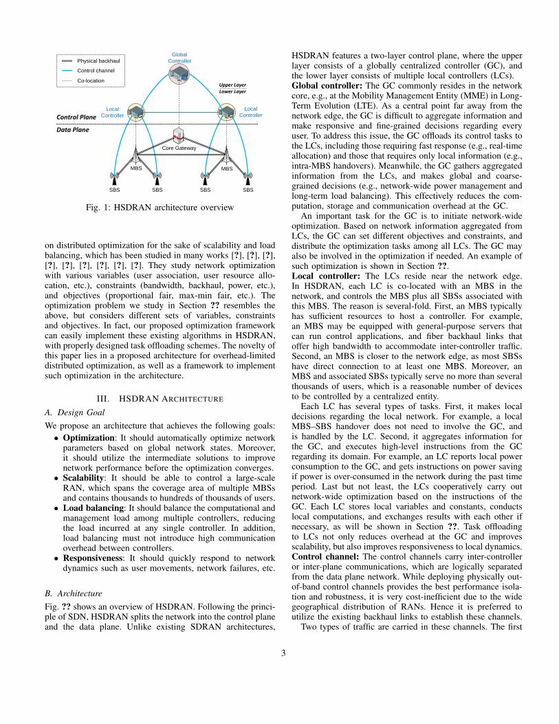
Fig. 1: HSDRAN architecture overview
on distributed optimization for the sake of scalability and loadbalancing, which has been studied in many works [?], [?], [?],[?], [?], [?], [?], [?], [?]. They study network optimizationwith various variables (user association, user resource allo-cation, etc.), constraints (bandwidth, backhaul, power, etc.),and objectives (proportional fair, max-min fair, etc.). Theoptimization problem we study in Section ?? resembles theabove, but considers different sets of variables, constraintsand objectives. In fact, our proposed optimization frameworkcan easily implement these existing algorithms in HSDRAN,with properly designed task offloading schemes. The novelty ofthis paper lies in a proposed architecture for overhead-limiteddistributed optimization, as well as a framework to implementsuch optimization in the architecture.
III. HSDRAN ARCHITECTURE
A. Design GoalWe propose an architecture that achieves the following goals:• Optimization: It should automatically optimize network
parameters based on global network states. Moreover,it should utilize the intermediate solutions to improvenetwork performance before the optimization converges.
• Scalability: It should be able to control a large-scaleRAN, which spans the coverage area of multiple MBSsand contains thousands to hundreds of thousands of users.
• Load balancing: It should balance the computational andmanagement load among multiple controllers, reducingthe load incurred at any single controller. In addition,load balancing must not introduce high communicationoverhead between controllers.
• Responsiveness: It should quickly respond to networkdynamics such as user movements, network failures, etc.
B. ArchitectureFig. ?? shows an overview of HSDRAN. Following the princi-ple of SDN, HSDRAN splits the network into the control planeand the data plane. Unlike existing SDRAN architectures,
HSDRAN features a two-layer control plane, where the upperlayer consists of a globally centralized controller (GC), andthe lower layer consists of multiple local controllers (LCs).Global controller: The GC commonly resides in the networkcore, e.g., at the Mobility Management Entity (MME) in Long-Term Evolution (LTE). As a central point far away from thenetwork edge, the GC is difficult to aggregate information andmake responsive and fine-grained decisions regarding everyuser. To address this issue, the GC offloads its control tasks tothe LCs, including those requiring fast response (e.g., real-timeallocation) and those that requires only local information (e.g.,intra-MBS handovers). Meanwhile, the GC gathers aggregatedinformation from the LCs, and makes global and coarse-grained decisions (e.g., network-wide power management andlong-term load balancing). This effectively reduces the com-putation, storage and communication overhead at the GC.
An important task for the GC is to initiate network-wideoptimization. Based on network information aggregated fromLCs, the GC can set different objectives and constraints, anddistribute the optimization tasks among all LCs. The GC mayalso be involved in the optimization if needed. An example ofsuch optimization is shown in Section ??.Local controller: The LCs reside near the network edge.In HSDRAN, each LC is co-located with an MBS in thenetwork, and controls the MBS plus all SBSs associated withthis MBS. The reason is several-fold. First, an MBS typicallyhas sufficient resources to host a controller. For example,an MBS may be equipped with general-purpose servers thatcan run control applications, and fiber backhaul links thatoffer high bandwidth to accommodate inter-controller traffic.Second, an MBS is closer to the network edge, as most SBSshave direct connection to at least one MBS. Moreover, anMBS and associated SBSs typically serve no more than severalthousands of users, which is a reasonable number of devicesto be controlled by a centralized entity.
Each LC has several types of tasks. First, it makes localdecisions regarding the local network. For example, a localMBS–SBS handover does not need to involve the GC, andis handled by the LC. Second, it aggregates information forthe GC, and executes high-level instructions from the GCregarding its domain. For example, an LC reports local powerconsumption to the GC, and gets instructions on power savingif power is over-consumed in the network during the past timeperiod. Last but not least, the LCs cooperatively carry outnetwork-wide optimization based on the instructions of theGC. Each LC stores local variables and constants, conductslocal computations, and exchanges results with each other ifnecessary, as will be shown in Section ??. Task offloadingto LCs not only reduces overhead at the GC and improvesscalability, but also improves responsiveness to local dynamics.Control channel: The control channels carry inter-controlleror inter-plane communications, which are logically separatedfrom the data plane network. While deploying physically out-of-band control channels provides the best performance isola-tion and robustness, it is very cost-inefficient due to the widegeographical distribution of RANs. Hence it is preferred toutilize the existing backhaul links to establish these channels.
Two types of traffic are carried in these channels. The first
3

Local Controller
Local Optimization
Module
Local Feasibility Enforcer
Global ControllerOptimization Manager
Global Optimization
Module
Global Feasibility Enforcer
Op
tim
izat
ion
init
ializ
atio
nPer-iteration information
exchange
Infeasible solution
Infeasible solution
Control Plane
Data Plane
Feasibility enforcement
exchange
Feasible solution for execution
Management Traffic
Computation Traffic
Execution Traffic
Fig. 2: Distributed optimization in HSDRAN.
type is inter-controller communications (eastbound traffic1)that coordinate decision making between controllers. This typeof traffic is carried on the inter-LC links and the GC–LClinks. Since the LCs reside with the MBSs which commonlyhave high-speed fiber links, these links are sufficient to carrythe eastbound traffic. The other type is control primitives andraw data transmitted between LCs and data plane elements.Since SBSs commonly have limited backhaul, control traffic onthese links (southbound traffic) should be minimal to minimizeinterference to data plane traffic. Only direct commands andnecessary information should be disseminated via these links.
IV. DISTRIBUTED OPTIMIZATION IN HSDRAN
Fig. ?? shows an overview of the optimization frameworkin the proposed architecture. The Optimization Manager atthe GC initiates and supervises the optimization process. Itinstructs the Optimization Modules at both GC and LCs forcoordinated optimization. The Optimization Modules carry outthe distributed optimization. They conduct local computationsand exchange results with each other during the optimization.
Many existing optimization algorithms are iterative methodsthat do not guarantee feasibility until convergence [?], [?]. TheFeasibility Enforcer transforms the intermediate (possibly in-feasible) solutions to feasible ones, via additional computationand information exchange. This way, the network can utilizethese solutions to gradually improve the network objectivewithout waiting for convergence. No computation happens inthe data plane, as only the solutions are translated into controlprimitives and sent to the data plane for execution.
1Note that while the first type of traffic involves upward traffic from LCsto GCs in the proposed controller hierarchy, we still refer to such trafficas eastbound traffic. The term northbound commonly describes the interfacebetween the control plane and the management plane in the SDN convention.
To illustrate the benefits of our architecture and framework,we study a concrete optimization problem in the RAN, and im-plement a classic algorithm of the problem in our architectureand framework. We study joint user association and downlinkresource allocation in HetNet RANs, considering radio, back-haul and power resource constraints. This is a typical networkoptimization problem as studied in many works [?], [?], [?],[?], [?], [?], with a different set of constraints and objectivefrom the above. Implementation of our proposed algorithm(and other similar algorithms in aforementioned researches)in fully centralized SDRANs results in low scalability, lowresponsiveness, and large overhead. On the contrary, ourproposed architecture and framework well address these issuesvia delegation-based task offloading.
A. System ModelThe network consists of multiple MBSs, denoted by M ={M1, . . . ,Mm}. Each MBS M ∈ M has multiple SBSs,denoted by SM = {SM1 , . . . , SMnM
}. All SBSs are denoted byS =
⋃M∈M SM . All BSs are denoted by B =M∪S .
We consider several kinds of resources in the network. Radioresources are defined in continuous time-frequency slots foreach BS, and can be shared among BSs with frequency reuse.We assume that all BSs share the same set of frequency bands,and define A > 0 as the total radio bandwidth of all bands thatare shared among all BSs (in unit time). Each BS B ∈ B hasbackhaul capacity of βB > 0 for serving user traffic. Further,each BS B ∈ B has a renewable power source, which canconstantly provide ρnB ≥ 0 power. Each BS is also connectedto the power grid, which will provide energy if the renewableenergy is not sufficient. However, the grid power is not free-to-use compared to local renewable power, hence an on-gridpower bound P ≥ 0 is enforced network-wide to limit the totalon-grid power used by all BSs. A BS’s power consumptionhas two parts. The fixed power consumption of BS B ∈ B isρfB ≥ 0. The dynamic power consumption is defined by powerslope ρtB > 0, which is the power consumed for transmittingunit bandwidth of radio signal with fixed transmit power. Thepower consumption of BS B on the grid is thus defined as
ρB =[ρfB + ρtB · aB − ρnB
]+, (1)
where [·]+ denotes the projection onto non-negative real num-bers, and aB is the total bandwidth used by BS B. Thenetwork-wide power bound is expressed as follows∑
B∈BρB ≤ P. (2)
We assume that P >∑B∈B [ρfB − ρnB ]+, meaning that the
on-grid power is sufficient to cover some radio transmissionin addition to all fixed part consumptions of BSs.
A set of users exist in the network, denoted by U ={U1, . . . , UK}. Each user receives signals from several BSs,including both MBS and SBS. To avoid strong interferencefrom MBS on users served by SBS, modern HetNets employsalmost blank subframes (ABSs), where some subframes areleft blank by the MBS for transmissions from/to SBSs. Denote
4

PB,U as the power received from BS B at user U . For eachuser U and BS B, the signal-to-interference-and-noise ratio(SINR) during non-ABS is
SINR+B,U =
PB,U∑B′ 6=B PB′,U +N0
, (3)
and for user U and SBS S ∈ S, the SINR during ABS is
SINR−S,U =PS,U∑
B′ 6=SB′ 6=M(S)
PB′,U +N0, (4)
where M(B) is the MBS with which SBS B is associated, orthe MBS itself if B is an MBS, and N0 is the noise power.The SINR of an MBS during ABS is always 0 for any user.
The spectral efficiency is defined based on the Shannoncapacity, where during ABS, it is
η+B,U = log2(1 + SINR+
B,U ), (5)
and during non-ABS, it is
η−B,U = log2(1 + SINR−B,U ). (6)
For each user, only signals with SINR above a threshold Υcan be successfully decoded. We denote BU as the set of BSs(namely candidate BSs) whose SINR at user U is at least Υduring either ABS or non-ABS, and UB as the set of users(namely candidate users) whose SINR from B is at least Υ.
TABLE I: Notations
Symbol MeaningM Set of MBSs; |M| = mSM Set of SBSs associated with MBS M ; |SM | = nM
S,B Set of all SBSs and all BSsU Set of all users; |U| = KA Total radio bandwidth shared by all BSsβB Backhaul capacity of BS BP Global on-grid power consumption limitρnB Renewable power at BS BρfB Fixed power consumption at BS BρtB Dynamic power slope for transmission at BS BρB On-grid power consumption of BS Bη+B,U , η
−B,U Spectral efficiency during non-ABS and ABS
Υ Global SINR thresholdBU Set of BSs with above-threshold SINR at user UUB Set of users with above-threshold SINR at BS BrU Aggregate bandwidth of user U (variable)xB,U Fraction of user U served by BS B (variable)a+B,U , a
−B,U Bandwidth allocation during non-ABS and ABS (variables)
αM ABS ratio at MBS M (variable)
Table ?? summarizes the notations used in this section.
B. Problem FormulationWe study joint user association and downlink resource al-location in the RAN. In user association, we decide theserving BS(s) for each user. We assume that each user can beassociated with multiple BSs, and define variable xB,U ∈ [0, 1]as the fraction of user U served by BS B. In practice, xB,Ucan be interpreted as the long-term association of the user, whomay be switched among multiple BSs for load balancing [?].
In resource allocation, we allocate resources in two perspec-tives. First, we need to decide the fraction of radio resourcesthat are dedicated to ABSs for each MBS, and we use variableαM ∈ [0, 1] to denote this fraction for each MBS M ∈ M.Second, we need to allocate radio resources, for both ABSsand non-ABSs, to each user, based on their associations. Weuse variable a+
B,U ∈ [0, A] to denote the bandwidth allocatedfor user U at BS B during non-ABS, and a−B,U ∈ [0, A]to denote the bandwidth allocated during ABS. Since MBSscannot transmit during ABSs, we have a−M,U = 0 for any MBSM and user U . In practice, radio resources are commonlysliced into unit-length time slots and subcarriers. However,variables αM , a+
B,U and a−B,U take real numbers, which canbe interpreted as the long-term allocation for SBSs and usersrespectively. Finally, we use variable rU ≥ 0 to denote theaggregate rate of user U from all candidate BSs.
The problem we study is formulated as follows:
max∑
U∈UwU log(rU ) (7)
s.t. rU ≤∑B∈BU
(η+B,Ua
+B,U + η−B,Ua
−B,U ), ∀U ∈ U ; (8)∑
B∈BU
xB,U = 1, ∀U ∈ U ; (9)
a+B,U + a−B,U ≤ A · xB,U , ∀U ∈ U , B ∈ BU ; (10)
a−M,U = 0, ∀M ∈M, U ∈ UM ; (11)∑U∈UB
a−B,U ≤ A · ωB · αM(B), ∀B ∈ B; (12)∑U∈UB
a+B,U ≤ A · (1− αM(B)), ∀B ∈ B; (13)∑
U∈UB
(η+B,Ua
+B,U + η−B,Ua
−B,U ) ≤ βB , ∀B ∈ B; (14)
∑B∈B
[ρfB + ρtB ·
∑U∈UB
(a+B,U + a−B,U )− ρnB
]+
≤ P; (15)
xB,U , αM ∈ [0, 1], a+B,U , a
−B,U ∈ [0, A], rU ∈ [0,maxSE ·A].
(16)
Explanation: The objective function (??) is the weightedproportional fairness of user rates, where wU is the weight ofuser U . In the objective function, user weights are determinedby the actual types of traffic of the users; for example, real-timevideo traffic should have larger weights than static webpageinquiries. These weights are periodically updated by eachuser’s local controller based on the traffic pattern of each userin the past period. Constraint (??) defines the user rate boundedby the allocated radio resources (variables) and the spectralefficiencies (constants) from all candidate BSs. Constraint (??)states the fractional constraint of each user. Constraint (??)bounds the allocated resources by the user association, en-forcing that the resources allocated from BS B cannot exceedthe fraction served by this BS. Constraint (??) states the non-transmission rule for MBS during ABS. Constraint (??) boundsthe total amount of ABS resources allocated to users by theallocated ABS resources from the MBS, where ωB is an indica-tor of whether BS B is an MBS (ωB = 0) or an SBS (ωB = 1).
5

Constraint (??) similarly bounds the non-ABS resources tousers. Constraint (??) enforces the backhaul bound of theaggregate user rate at each BS. Constraint (??) enforces thenetwork-wide on-grid power bound. Constraint (??) specifiesthe range of each variable, where maxSE is the maximumpossible spectral efficiency.
For the above problem, the Slater’s condition is satisfiedsince P >
∑B∈B [ρfB − ρnB ]+, βB > 0 for ∀B ∈ B, A > 0,
and η+B,U > 0 and η−B,U > 0 for ∀B ∈ B,∀U ∈ UB . To
see this, note that we can always set xB,U = 1/|BU | forU ∈ U and B ∈ BU , and αM = 0.5 for M ∈ M. Resourceallocations a+
B,U and a−B,U can be made to strictly satisfyConstraints (??), (??), (??), (??), and (??), by assigning anarbitrarily small value ε > 0 to a+
B,U and a−B,U for any B ∈ Band U ∈ UB , except a−B,U = 0 for MBS B ∈ M. Also, userrates rU can be set as strictly smaller than the sum of ratesfrom all candidate BSs in Constraint (??). Since the problem ismaximizing a concave function subject to convex constraints,the Slater’s condition ensures strong duality, meaning thatthe primal optimal objective value equals the dual optimalobjective value. Hence we can use primal-dual algorithms likethe dual subgradient method to solve it.
C. Dual Subgradient MethodWhile there are many methods to solve this problem, we solveit using the dual subgradient method (DSM) following existingwork [?], [?]. DSM is preferred in large-scale optimization dueto its possibility for distributed realization via dual decomposi-tion, hence it will benefit from the above proposed HSDRANarchitecture. Note that primal and dual decompositions arewidely employed in wireless optimizations, which will allbenefit from HSDRAN.
Dual problem: Define z = (r,x,a+,a−,α) as the primalvariable vector, where bold symbols denote the correspondingvariable vectors. To start with, we define the subspace forprimal variables as
Π = {z ≥ 0 | (??), (??), (??)}. (17)
For the other constraints, we associate dual variables γUfor (??), σB,U for (??), µB for (??), νB for (??), λB for (??),and δ for (??). Define p = (γ,σ,µ,ν,λ, δ) as the dualvariable vector, the dual subspace is defined as {p ≥ 0}.
The Lagrangian of the primal problem is as follows
L(z,p) =∑
U∈UwU log(rU )− pTg(z) (18)
=∑
U∈UwU log(rU )
−∑
U∈UγU
(rU −
∑B∈BU
(η+B,Ua
+B,U + η−B,Ua
−B,U
))−∑
U∈U
∑B∈BU
σB,U
(a+B,U + a−B,U −A · xB,U
)−∑
B∈BµB
(∑U∈UB
a−B,U −A · ωB · αM(B)
)−∑
B∈BνB
(∑U∈UB
a+B,U −A · (1− αM(B))
)−∑
B∈BλB
(∑U∈UB
(η+B,Ua
+B,U + η−B,Ua
−B,U )− βB
)
− δ
∑B∈B
[ρfB + ρtB ·
∑U∈UB
(a+B,U + a−B,U )− ρnB
]+
− P
,
where g(·) denotes the vector of all primal constraint functionsexcept Constraints (??), (??) and (??). The dual problem is
minp≥0D(p), (19)
whereD(p) = maxz∈Π L(z,p). (20)
Given the dual problem, for any p ≥ 0, the subgradi-ents of D(p) consists of g(z) for any z ∈ Π such thatL(z,p) = D(p), as observed in [?]. In other words, the setof subgradients of the dual function (??) is given by the setof primal constraint function values at any primal solution inΠ that achieves the maximum of the dual function. Hence wecan utilize this simple subgradient structure in our DSM.Dual subgradient method: DSM is an iterative method thatupdates the primal and dual solutions in each iteration, untilconvergence. Initially, the primal variables are initialized tosome value in Π, and the dual variables are initialized to 0.We can always use an all-0 solution as the initial primal point,though other initial points, such as evenly distributed userassociation and resource allocation among all entities, will alsowork with little impact on performance. Then, in each iterationi, the algorithm conducts the following two steps:Primal update: The primal variables in the i-th iteration (de-noted by z(i)) are obtained by solving the following problem
z(i) = arg maxz∈Π L(z,p(i−1)). (21)
Dual update: The dual variables in the i-th iteration (denotedby p(i)) are updated as
p(i) = [p(i−1) + θig(z(i))]+, (22)
where θi is the step size for the i-th iteration.Remark 4.1: Based on classic convergence results of the
subgradient method, DSM converges to within a given errorbound of the optimal solution when constant step size or steplength is used, and to the optimal when diminishing step sizesare used [?]. This is not affected by the specific implemen-tation of the algorithm, for example, the decomposition-basedimplementation proposed below.
D. Distributed Algorithm via Dual DecompositionDSM features dual decomposition-based distributed implemen-tation of each iteration. In particular, each primal update ordual update step is decomposed into per-user update, per-BSupdate, and per user-BS pair update.
1) Primal Update Decomposition: Recall that the primal up-date step is to obtain the primal variable values that maximizethe Lagrangian function in (??). Define xU = (xB,U |B ∈BU ) to be the vector of association variables for user U ,and aB = (a+
B,U , a−B,U |U ∈ UB) to be the vector of
all user allocation variables associated with BS B, for bothABSs and non-ABSs. Also define R = [0,maxSE · A],XU = {xU ∈ [0, 1]|xU | |
∑B∈BU
xB,U = 1}, AB =
6

maxz∈Π L(z,p(i− 1)) =∑
U∈UmaxrU∈R (wU log(rU )− γ(i−1)
U rU ) +∑
U∈UAmaxxU∈XU
∑B∈BU
σ(i−1)B,U xB,U
+A∑M∈M
maxαM∈Λ
αM∑
B∈SM∪{M}
(µ(i−1)B · ωB − ν(i−1)
B ) +∑B∈B
maxaB∈AB
( ∑U∈UB
(ζ−,(i−1)B,U a−B,U + ζ
+,(i−1)B,U a+
B,U
)−δ(i−1)
[ρfB + ρtB ·
∑U∈UB
(a+B,U + a−B,U )− ρnB
]+)+A|B|+
∑B∈B
λ(i−1)B βB + δ(i−1)P
(23)
{aB ∈ [0, A]|aB | | if B ∈ M, a−B,U = 0 for ∀U ∈ UB}, andΛ = [0, 1] to be the projection of subspace Π over each variableor variable vector rU per U ∈ U , xU per U ∈ U , aB perB ∈ B, and αM per M ∈M, respectively. The maximizationproblem can be re-written as in (??), where
ζ−,(i−1)B,U = (γ
(i−1)U − λ(i−1)
B )η−B,U − σ(i−1)B,U − µ
(i−1)B , (24)
ζ+,(i−1)B,U = (γ
(i−1)U − λ(i−1)
B )η+B,U − σ
(i−1)B,U − ν
(i−1)B . (25)
Based on (??), the primal update step at iteration i can bedivided into several steps:
1) rU update: For each user U , its rate rU is updated asr
(i)U = min{ wU
γ(i−1)U
, A ·maxSE}.2) xB,U update: Each user U picks the BS B∗ =
arg maxB{σ(i−1)B,U }, and updates x(i)
B∗,U = 1 and x(i)B′,U =
0 for B′ ∈ BU \ {B∗}.3) αM update: For each MBS M , if
∑B∈SM∪{M}(µ
(i−1)B ·
ωB − ν(i−1)B ) > 0, α(i)
M = 1; otherwise, α(i)M = 0.
4) a+B,U , a
−B,U update: User resource allocation is by solving
the following optimization problem for each BS B ∈ B:
maxaB∈AB
(∑U∈UB
(ζ−,(i−1)B,U a−B,U + ζ
+,(i−1)B,U a+
B,U
)−δ(i−1)
[ρfB + ρtB ·
∑U∈UB
(a+B,U + a−B,U )− ρnB
]+).
(26)Note that although this involves maximization of a non-linear function, the following greedy algorithm achievessuch maximization. For each BS B and each user U ∈UB , both a
+,(i)B,U and a
−,(i)B,U are initialized to 0. First, we
find all users U ∈ UB such that ζ−,(i−1)B,U ≥ δ(i−1)ρtB ,
and assign a−,(i)B,U = A. Next, we find all users U ∈ UB
such that ζ+,(i−1)B,U ≥ δ(i−1)ρtB , and assign a
+,(i)B,U = A.
Third, for the rest unassigned variables in aB , we dothe following steps: let a∗B = (ρnB − ρ
fB)/ρtB be the
radio resources that can be served from the renewablepower source; if a∗B > 0, we then consecutively pick userU− = arg maxU∈UB{ζ
−,(i−1)B,U ≥ 0 | a−,(i)B,U = 0}, and
user U+ = arg maxU∈UB{ζ+,(i−1)B,U ≥ 0 | a+,(i)
B,U = 0} (forMBSs, only U+ is considered); if ζ−,(i−1)
B,U− > ζ+,(i−1)B,U+
and ζ−,(i−1)B,U− ≥ 0, we let a−,(i)B,U− = min{A, a∗B}, and
let a∗B = a∗B − a−,(i)B,U− ; else if ζ−,(i−1)
B,U− ≤ ζ+,(i−1)B,U+ and
ζ+,(i−1)B,U+ ≥ 0, we let a+,(i)
B,U+ = min{A, a∗B}, and let
a∗B = a∗B − a+,(i)B,U+ ; continue this until a∗B = 0 or no
such user can be found.2) Dual Update Decomposition: The dual update step can
also be divided into several steps based on (??): each user Uupdates γU , each BS updates µB , νB , λB , each user–BS pairupdates σB,U , and globally the network updates δ. Detailedsteps for the i-th iteration are shown in (??)–(??). Note that γUis updated at the user side, µB , νB , λB are updated at the BSside, and δ is updated jointly by all BSs. σB,U update involvesboth BS and user, hence can be conducted at either side basedon availability of computational and storage resources.
E. Delegation-based Implementation in HSDRANThe above distributed algorithm assumes that all BSs, all usersand the network core would be involved in the computationprocess. In practice, such cooperation is subject to controlcapability and overhead constraints, and thus is not commonlyavailable in modern RANs. For example, user devices aretypically out of the control of the network operator; while SBSsare controlled, they may lack either computational resources(Remote Radio Heads in the C-RAN architecture) or networkbandwidth (wireless-backhauled SBSs). In HSDRAN, we uti-lize only the control plane to carry out the computations, henceavoiding overhead in the data plane, meanwhile achieving loadbalancing compared to fully centralized SDRAN proposals. Weuse a delegation-based scheme to achieve this goal.
In our proposed scheme, task delegation is to find a delegateLC for each user and each BS, which essentially stores data,carries out computation, and exchanges information on behalfof the delegated user or BS. In particular, each MBS’s tasksare delegated to its associated LC. Each user is delegated tothe LC at the nearest MBS. We use UDM to denote the setof users delegated at the LC at MBS M . Similarly, eachSBS delegates all its tasks to the LC at the MBS that it isassociated with. Each LC stores the corresponding informationand optimization variables for its delegated users and BSs.Information exchange happens only within the control plane,between different LCs and between LCs and the GC. Thiscreates a logical separation between data plane user trafficand control plane management traffic, which is beneficial forperformance isolation and guarantee.
Next we analyze the detailed storage and computation del-egation process, and its storage and communication overhead.Storage: The GC stores the network-wide dual variable δ, andthe network-wide power bound P . For each variable involvingonly the user (rU and γU ), it is stored at the delegate LC ofthe user. For each variable involving only the BS (αM , µB ,
7
γ(i)U =
[γ
(i−1)U + θi
(r
(i)U −
∑B∈BU
(η+B,Ua
+,(i)B,U + η−B,Ua
−,(i)B,U
))]+(27)
σ(i)B,U =
[σ
(i−1)B,U + θi
(a
+,(i)B,U + a
−,(i)B,U −A · x
(i)B,U
)]+(28)
µ(i)B =
[µ
(i−1)B + θi
(∑U∈UB
a−,(i)B,U −A · ωB · α
(i)M(B)
)]+(29)
ν(i)B =
[ν
(i−1)B + θi
(∑U∈UB
a+,(i)B,U −A · (1− α
(i)M(B))
)]+(30)
λ(i)B =
[λ
(i−1)B + θi
(∑U∈UB
(η+B,Ua
+,(i)B,U + η−B,Ua
−,(i)B,U )− βB
)]+(31)
δ(i) =
[δ(i−1) + θi
(∑B∈B
[ρfB + ρtB ·
∑U∈UB
(a+B,U + a−B,U )− ρnB
]+− P
)]+
(32)
νB and λB), it is stored at the delegate LC of the BS. Othervariables (xB,U , a+
B,U , a−B,U and σB,U ) are related to bothBS and user, which may have different delegate LCs. In theabove primal update step, since each user picks only one BSin each iteration, xB,U should be stored at the user delegatefor consistent selection. a+
B,U and a−B,U are local resourceallocations at each BS, hence are stored at the BS delegateto facilitate local update of all related dual variables includingµB , νB , λB . We also let σB,U be stored at the BS delegate,merely to facilitate its local update.
Non-variable storage involves user weights wU (stored atuser delegate), BS–user spectral efficiencies η+
B,U and η−B,U(stored at BS delegate where they are extracted), backhaulcapacities βB (stored at BS delegate), and power parame-ters ρfB , ρ
nB , ρ
tB (stored at BS delegate). Other constants are
shared globally, including total bandwidth A and maximumspectral efficiency maxSE. To sum up, each LC at MBS Mstores 3|SM | + 4 + 3
∑B∈SM∪{M} |UB | local variables and
4|SM |+4+2∑B∈SM∪{M} |UB | local constants for delegated
BSs, and 2|UDM |+∑U∈UD
M|BU | local variables and |UDM | local
constants for delegated users. The GC stores only one variable,one constant power bound, and other shared information.Communications: Communications are incurred when infor-mation needed for a variable update is stored at other LCs orthe GC. Note that most information is stored locally, henceonly variables and constants involving both BS and user needto be exchanged, and it only happens when a candidate BSof a user has a different delegate from the user’s delegate.We analyze the number of messages (one message carries oneconstant or variable value) needed in each iteration:
1) rU , αM , µB , νB , λB update: all information is locallystored at delegate LCs, hence no communications needed.
2) xB,U update: user delegate of U needs σ(i−1)B,U from the BS
delegate if BS B ∈ BU has a different delegate from userU . Since xB,U update is to pick one BS with maximumσ
(i−1)B,U , each LC only needs to transmit the largest σ(i−1)
B,Uvalue of all its delegated candidate BSs of user U , if any.
3) a+B,U , a
−B,U update: variables λ
(i−1)B , σ
(i−1)B,U , µ
(i−1)B ,
ν(i−1)B and other power constants are local at BS delegate
of B. Delegate of B needs γ(i−1)U for each candidate user
U , from the user delegate of U if different from delegateof B. Variable δ(i−1) is needed from the GC.
4) γU update: user delegate of U needs the per-user rate(η+B,Ua
+,(i)B,U + η−B,Ua
−,(i)B,U
)from each candidate BS’s
delegate. Since the update only needs the sum rate,each LC at MBS M transmits the aggregated rate∑B∈SM∪{M}
(η+B,Ua
+,(i)B,U + η−B,Ua
−,(i)B,U
)of all candi-
date BSs of U within its control, to delegate of U .5) σB,U update: BS delegate of B needs x
(i)B,U from the
user delegate of U . Note that in the x update, only oneBS is selected per-iteration for each user. Hence only theselected BS needs to be aware of the selection, and eachLC sends 1 message per delegated user.
6) δ update: the GC only needs the aggregate power con-sumption from each LC, hence each LC sends 1 message.
The summarized storage and communication overheads canbe found in Table ?? and ?? respectively.
TABLE II: Storage Overhead
LC GCConsts 4|SM |+ 4 + 2
∑B∈SM∪{M}
|UB | |UDM |
Vars 3|SM |+ 4 + 3∑
B∈SM∪{M}|UB | 2|UD
M |+∑
U∈UDM|BU |
Vars-PFT∑
B∈SM∪{M}|UB | 0
TABLE III: Average Communication Overhead
LC GCPrimal update 4|UD
M |+ 1 |M|Dual update 4|UD
M |+ 1 |M|PFT 2 2|M|
Note that most of the communications are between LCs atnearby MBSs, as users delegated at the LC with one MBSare very unlikely to receive strong-enough signals from otherfar-away MBSs or SBSs. The GC has very little storage andcommunication overhead, as it does not need to store per-user and per-BS information. Each LC only stores informationregarding local users and BSs, and exchanges information withonly nearby LCs. Therefore our proposed method well utilizeslocality in RANs to reduce overhead.
Remark 4.2: In the above process, the delegation of usersis with no regard to the specific association of users, since
8

each user–BS pair with SINR above the threshold Υ needsto participate in the optimization process, regardless of thefinal association of users. The same holds for any optimizationthat involves user association as variables, e.g., even for userassociation with massive Multi-Input Multi-Output (MIMO)networks [?]. On the other hand, if an optimization problemtakes fixed user association as input, the delegation processshould consider the association of users. For example, ifa user is associated with one BS, its delegation should beat or directly connected to this BS to facilitate informationaggregation for this user; if multiple BSs serve the same useras in massive MIMO networks, the one with maximum signalstrength can be selected.
F. Primal Feasibility TransformationIn the above, the obtained primal solution in each iteration maynot be feasible. To better utilize these intermediate solutions,they need to be transformed to solutions that obey the primalconstraints. We call this process primal feasibility transforma-tion (PFT). The obvious merit of PFT is to gradually improvenetwork performance during the optimization process (whichcan be pretty long due to the intrinsic complexity of wirelessoptimization), without waiting for convergence.
Since the primal constraint set is convex, many convexoptimization methods can be used for PFT. However, we seekfor a distributed method that does not add much overheadto the above iterative method. We propose the following 2-step PFT method: first, we use the averaging scheme in [?] toobtain an approximate feasible solution, whose total feasibilityviolation is bounded as shown in [?]; then, we use linearscaling to further transform it to a feasible solution.
Specifically, consider the PFT conducted after iteration i.We first obtain the average of each primal variable over thefirst i iterations. Denote the average using vector z(i), we have
z(i) =1
i
∑i
j=0z(j), (33)
where z(0) is the initial point.Since z(i) still may not be feasible, we further scale the
primal variables to enforce the feasibility constraints. Observethat all the primal constraints are linear except Constraint (??),which is a summation of linear functions projected onto thenon-negative real number set. Also observe that variablesx(i) and α(i)’s bounds are already satisfied in Π due to theconvexity of Π, and are only used to bound the radio resourceallocations a+,(i) and a−,(i). On the other hand, the rates r(i)
are also determined by allocation variables a+,(i) and a−,(i).Therefore, we only need to scale variables a+,(i) and a−,(i)based on violation of Constraints (??), (??), (??), (??), and(??). The scaling is per-BS based, and is shown as follows:
1) For each BS B and user U ∈ UB , if a+,(i)B,U + a
−,(i)B,U >
A · x(i)B,U , then we multiply both a+,(i)
B,U and a−,(i)B,U by A ·x
(i)B,U/(a
+,(i)B,U + a
−,(i)B,U ).
2) For each SBS B, if∑U∈UB a
−,(i)B,U > A · α(i)
M(B),
we multiply a−,(i)B,U for each U ∈ UB by (A ·
α(i)M(B))/(
∑U∈UB a
−,(i)B,U ); for MBS B, we set a−,(i)B,U = 0
for U ∈ UB .3) For each BS B, if
∑U∈UB a
+,(i)B,U > A · (1 − α
(i)M(B)),
we multiply a+B,U for each U ∈ UB by (A · (1 −
α(i)M(B)))/(
∑U∈UB a
+,(i)B,U ).
4) For each BS B, if∑U∈UB (η+
B,U a+,(i)B,U + η−B,U a
−,(i)B,U ) >
βB , we multiply a+B,U and a−B,U for each U ∈ UB by
βB/(∑U∈UB (η+
B,U a+,(i)B,U + η−B,U a
−,(i)B,U )).
5) In the global view of the network, let Pvio =∑B∈B
[ρfB + ρtB ·
∑U∈UB (a
+,(i)B,U + a
−,(i)B,U )− ρnB
]+−
P . If Pvio > 0, we need to scale resources. Note thatboth the fixed power consumption and the part of radioresources covered by renewable power cannot be scaled,thus we compute the scalable power consumption per BSas PscaleB = ρtB
∑U∈UB (a
+,(i)B,U + a
−,(i)B,U ) − [ρnp − ρfp ]+.
We multiply each BS B’s total resources(thus a+
B,U and a−B,U for ∀U ∈ UB) by(1− Pscale
B
(ρtB∑
U∈UB(a
+,(i)B,U +a
−,(i)B,U ))
· Pvio∑B∈B Pscale
B
), which
enforces the total power constraint.After the above, the obtained resource allocations a+ and
a− satisfy Constraints (??), (??), (??), (??), and (??). The rateof each user U ∈ U is then re-computed as
r(i)U =
∑B∈BU
(η+B,U a
+,(i)B,U + η−B,U a
−,(i)B,U ). (34)
The obtained solution z(i) is now primal feasible.Storage: Additional
∑B∈SM∪{M} |UB | variables at each LC,
as shown below.Communications: The averaging process does not involvecommunications. The scaling process mostly uses local infor-mation stored at each BS delegate, except x(i)
B,U needed fromeach user delegate in step 1, and the ratio Pvio/
∑B∈B PscaleB
from the GC in step 5. Since the variables x(i)B,U are exchanged
per-iteration for dual update, each BS delegate can keep acopy of their average values, adding
∑B∈SM∪{M} |UB | to the
storage of each LC while eliminating the communications ofanother round of x variables. Hence per iteration, each LConly aggregates total scalable power for all delegated BSs,and sends it to the GC; the GC then broadcasts the ratioPvio/
∑B∈B PscaleB to all LCs. The communication overhead
at each LC is 2 messages (1 input and 1 output), and that atthe GC is 2|M| messages.
Since the dual subgradient method is not a descent method,the current feasible solution may be worse than the bestfeasible solution ever found. Hence the GC records the bestfeasible solution, and instructs the LCs to execute it untilimproved in the future. This adds a copy of local primalvariables of the best solution at each controller, and another2 messages between each LC and the GC, one for reportingaggregated objective value, another for informing the bettersolution between current and previous best.
Remark 4.3: The above PFT does not affect the conver-gence of the optimization. Moreover, as proved in [?], if
9

the optimization converges to the optimal solution, so doesthe averaging sequence. Since linear scaling does not affectconvergence, the primal solution after PFT also converges tothe optimal. The pros of using PFT is to improve averagenetwork objective by utilizing intermediate solutions. Yet thecost is the additional overhead, for example, the additional run-ning time per iteration, and the extra storage/communicationoverhead on each controller. In this sense, a PFT methodshould have low complexity in order not to add non-negligibleoverhead to the optimization. For example, the above PFTmethod runs in linear time, uses linear space, and adds minimalcommunication overhead per controller.
Remark 4.4: While we have studied a specific optimizationproblem in RAN as an illustrative example, the same archi-tecture and technique can be applied to dealing with variousoptimization problems and methods in the RAN. Specifically,implementing distributed optimization in HSDRAN essentiallyinvolves three steps: 1) finding a distributed/decomposition-based algorithm, 2) defining computation delegation to localcontrollers, and 3) finding a PFT method and also define itsdelegation scheme. Many methods can be used for step 1,including dual subgradient method, ADMM [?], etc. In step2, an efficient computation delegation scheme should followthe principle so as to minimize the communication overheadbetween controllers, and can be analytically derived fromthe optimization method found in step 2. The PFT step isoptional, and is only useful when the method in step 1 doesnot guarantee primal feasibility during iterations.
Remark 4.5: In the above optimization, we assume theRAN is operated by a single service provider. In a multi-operator network [?], each operator may have a different setof network objective and constraints, and network resourcesare dynamically shared among different operators. Our archi-tecture and optimization framework can be used orthogonallywith network slicing techniques such as RadioVisor [?]. Inthis case, each operator initiates its own HSDRAN controlplane, with both the GC and the LCs in its own allocatednetwork slice. The global network slice manager, which has ahigher hierarchy than the operators’ GCs, will make dynamicradio resource allocation for each operator. This allocation willthen provide the available radio resources to each operator asinput to our HSDRAN optimization framework. Modeling andcoordinating multi-operator competition is a different problemthan the one we tackle, and is among our future researchdirections.
V. PERFORMANCE EVALUATION
A. Experiment SettingsWe implemented our proposed optimization under both central-ized SDRAN and HSDRAN using Matlab, and compared theiroverhead. General default experiment parameters are listed inTable ??. Parameters marked as “varying” are varied in theexperiments. Fig. ?? shows an example of the topology. 3MBSs are deployed by default, as shown by MBS 1–3 in thefigure, each with 4 randomly deployed SBSs. When increasingMBSs, each MBS is added in order of 1–7; MBSs excessing7 are added in the same manner, i.e., in clockwise sense
MBS 1
MBS 2
MBS 3
MBS 4
MBS 5
MBS 6
MBS 7
MBS
SBS
Fig. 3: Experiment topology where MBSs 1–3 are by default,and MBSs 4–7 and beyond are added in some experiments.SBSs are randomly deployed within each MBS.
around inner MBSs. We considered two types of users: normalusers that are uniformly distributed in the simulated area, andclustered users that are within 40m of an arbitrary SBS.
TABLE IV: General Experiment Parameters
# MBSs 3 (varying)# SBSs per MBS 4 (varying)Inter-site distance [?] 500 mUser density [?] 400 /km2 (varying)Clustered user ratio [?] 2/3Total radio bandwidth (A) [?] 10 MbpsNetwork-wide power bound (P) 400 Watts (varying)Noise [?] −174 dBm/HzMinimum SINR (Υ) −10 dB (varying)
Default wireless, backhaul and power parameters are shownin Table ??. In the experiments, we varied different param-eters. Each experiment ran the iterative algorithm for 10000iterations, with an initial point that distributes radio resourcesevenly among users. Step size of 0.0007 is empirically chosen.In each iteration, we utilized the PFT in Section ?? to obtaina feasible solution, executed it if better than the current, andrecorded the average objective throughout the optimization. Weran each experiment for 20 times under the same setting andtook the average. Experiments were run on a Macbook Airwith Intel Core i7 1.7GHz CPU and 8GB memory.
TABLE V: Wireless, Backhaul and Power Parameters for BSs
MBS SBSPath loss (d in km) [?] 37.6 log10(d) + 128.1 36.7 log10(d) + 140.7Transmit power [?] 46 dBm 30 dBmBackhaul [?] 2000 Mbps 200 MbpsFixed power cons. [?] 780 Watts 13.6 WattsTrans. power slope [?] 18.711 Watts/MHz 0.4 Watts/MHzRenew. power source [?] 696 Watts 15.66 Watts
10

100 200 300 400 500 600 700Density (users/km2)
-1000
-500
0
500
Obj
ectiv
e (s
um o
f log
)
(a) Network objective vs. user density
1 2 3 4 5 6 7# MBSs
-1000
-500
0
500
Obj
ectiv
e (s
um o
f log
)
(b) Network objective vs. MBSs
1 2 3 4 5 6 7# SBSs per MBS
-800
-600
-400
-200
0
Obj
ectiv
e (s
um o
f log
)
(c) Network objective vs. SBSs / MBS
300 350 400 450 500 550 600Total power bound (Watts)
-600
-400
-200
0
Obj
ectiv
e (s
um o
f log
)
(d) Network objective vs. power bnd
Fig. 4: Network objectives with varying user densities, MBSs, SBSs per MBS and total power bounds.
200 400 600Density (users/km2)
0
2000
4000
6000
8000
Avg
. con
trol
ler
stor
age
(var
s)
CentralizedHSDRAN
(a) Controller storage vs. user density
10 20 30 40# MBSs
0
2
4
6
Avg
. con
trol
ler
stor
age
(var
s) 104
CentralizedHSDRAN
(b) Controller storage vs. MBSs
2 4 6# SBSs per MBS
0
2000
4000
Avg
. con
trol
ler
stor
age
(var
s)
CentralizedHSDRAN
(c) Controller storage vs. SBSs / MBS
-20 -10 0Minimum SINR (dB)
0
2000
4000
6000
8000
Avg
. con
trol
ler
stor
age
(var
s)
CentralizedHSDRAN
(d) Controller storage vs. min. SINR
Fig. 5: Average controller storage overhead with varying user densities, MBSs, SBSs per MBS and minimum SINR.
200 400 600Density (users/km2)
0
100
200
300
Com
m. (
msg
s) /
itera
tion
LC avg.GC
(a) Comm. vs. user density
10 20 30 40# MBSs
0
100
200
300
400
Com
m. (
msg
s) /
itera
tion
LC avg.GC
(b) Comm. vs. MBSs
2 4 6# SBSs per MBS
0
50
100
150
200
Com
m. (
msg
s) /
itera
tion
LC avg.GC
(c) Comm. vs. SBSs per MBS
-20 -15 -10 -5 0Minimum SINR (dB)
0
200
400
600
800
Com
m. (
msg
s) /
itera
tion
LC avg.GC
(d) Comm. vs. min. SINR
Fig. 6: Average controller communication overhead with varying user densities, MBSs, SBSs per MBS and minimum SINR.
B. Experiment Results
Fig. ?? shows the network objectives with varying user den-sities, MBSs, SBSs per MBS and total power bounds. Barsshow the average objective values over all iterations. Error bars(“I”-like lines) show the initial objective values and the finalobjective values as lower and upper bounds respectively. Thechange of objective values follows intuitive analysis, wherethe network objective decreases when users or MBSs increase(the latter due to decreased per-MBS power), and increaseswhen number of SBSs or power bound increases (both due tomore available resources). In many cases, the average networkobjective is noticeably higher than the initial network objective,for example, when user density, number of MBSs or powerbound is low, or when number of SBSs is high. We alsoobserve that the final network objective is noticeably higher
than the initial objective in these cases. This shows that ourproposed PFT indeed increases average network objective.
Fig. ?? shows the average per-controller storage overhead(number of variables) with varying user densities, MBSs, SBSsper MBS and minimum SINR requirement. We compare ourHSDRAN implementation to a fully centralized implementa-tion where all computations are conducted at the GC. In thenetwork, the number of users dominates the number of BSs,hence the storage overhead grows linearly with user density.On the other hand, while more MBSs greatly increases storagein the centralized implementation, it almost has no impact onHSDRAN, which well illustrates how HSDRAN achieves loadbalancing and scalability. While the number of SBSs indeedhas some impact on storage, the impact is minimal, given thatmost users receive strong-enough signal from at most one SBS.Finally, storage decreases as minimum SINR increases, due to
11

that fewer BSs are in the candidate set of each user. In allcases, the per-controller storage overhead is much lower inHSDRAN than in the centralized implementation. Note thatwe also plotted the 95% confidence intervals for the 20 timesof tests. However, the scale of the confidence intervals are toosmall compared to the mean value, hence cannot be well visiblefrom the figures. In average, the scale of the 95% confidenceintervals are within 0.5% of the mean values.
Fig. ?? shows the per-controller communication overheadwith varying user densities, MBSs, SBSs per MBS and mini-mum SINR requirement. No inter-controller communication isneeded in the centralized implementation. We show both theaverage per-LC communications, and the communications atthe GC. In all cases, the GC incurs very little communicationoverhead. LC communications increase with user density dueto more exchanged information, while GC communicationsremain the same. On the other hand, more MBSs does notalways increase LCs’ communications; the LC at each MBSonly communicates with LCs at nearby MBSs, hence thecommunications reach a balance point after a certain amountof increase. This validates that HSDRAN utilizes locality toreduce communication overhead, leading to great scalabilityand load balancing advantages. GC communications increaselinearly with the number of MBSs (thus LCs), which matchesour analysis. The number of SBSs basically does not af-fect communications, as each user typically receives strong-enough signal from at most one SBS. With increasing SINRthreshold, LC communications go down drastically due toless chance that a user receives signals from two MBSs(or associated SBSs). This shows how locality is crucial inreducing communication overhead. We also plotted the 95%confidence intervals for LC average communication overhead;GC communication is only dependent on the number of LCs,hence remains the same for all the 20 runs. In average, thescale of the 95% confidence intervals are within 3% of themean values.
To summarize, HSDRAN is able to balance load and reduceoverhead (e.g. storage) at each controller, avoiding single-pointbottleneck at the central controller. It utilizes network localityto limit communication overhead incurred at each controller.With PFT, it can also improve average network performancecompared to using the initial solution until convergence.
Remark 5.1: While HSDRAN features its distributed con-trol plane, fully centralized (global) control applications canstill be readily deployed at the GC in HSDRAN. In fact,by offloading locality-aware applications such as distributedoptimization, the GC can dedicate more computation powerto global applications. HSDRAN can thus be viewed as aperformance-enhancing extension to centralized SDRAN.
VI. DISCUSSIONS
Online optimization: Network dynamics happen frequentlyin RANs due to user mobility, channel fluctuation, etc. Whileour proposed framework is for static optimization, it can beapplied to online optimization with modifications. To respondto network dynamics, the LCs need to aggregate real-timenetwork statistics from the data plane. When dynamics happen
within an LC’s control domain, they will be accounted forin future iterations of the optimization. Using our delegationscheme, the added storage and communication overhead can beclose to none, because only results of each iteration need to beexchanged. In practice, the optimization may not converge dueto frequent dynamics. Applying PFT, the network can alwaysbenefit from the optimization instead of waiting for conver-gence. However, the current averaging-based PFT method isnot suitable for frequent network dynamics. Advanced onlineoptimization and PFT methods are within our future work.Multi-layer control plane: HSDRAN has a two-layer controlplane. In the future, more complex communication modelsneed more layers for further scalability and load balancing.E.g., powerful SBSs can host another layer of LCs for D2Dcommunications [?], vehicular communications, or wirelesssensor networks [?]. Advanced distributed optimization andoffloading techniques are in need for this architecture.Logically centralized control plane: In traditional SDN,scalability is achieved by the so-called logically centralizedcontrol plane, where multiple copies of the global controllerare deployed for load balancing. However, each controller stillneeds to keep a global view, hence it cannot reduce storageand information aggregation overhead, and also incurs com-munications between controllers. On the contrary, HSDRANleverages locality in RANs, letting each LC maintain only localinformation, while the GC only receives and stores aggregatedinformation from LCs. This effectively reduces storage andcommunication overhead at any controller.
VII. CONCLUSIONS
In this paper, we proposed an HSDRAN architecture thatachieves self-optimization, scalability, load balancing, and re-sponsiveness at the same time. The architecture deploys localcontrollers in additional to the global controller to offloadcontrol tasks to the network edge. Besides local decisionmaking and execution of global decisions, the local controllersalso participate in globally coordinated network optimization.We then presented a framework to implement optimization inHSDRAN. We used a paradigmatic user association and down-link resource allocation problem to illustrate the benefits of ourarchitecture and framework. The problem was solved using adistributed dual subgradient method. Via extensive simulations,we showed how our architecture and framework can improveaverage network objective with balanced storage usage at eachcontroller and limited inter-controller communications.
REFERENCES
[1] 3GPP, “Further Advancements for E-UTRA, Physical Layer Aspects(Release 9),” Tech. Rep., 2010.
[2] H. Ali-Ahmad, C. Cicconetti, A. de la Oliva, V. Mancuso, M. R. Sama,P. Seite, and S. Shanmugalingam, “An SDN-Based Network Archi-tecture for Extremely Dense Wireless Networks,” in IEEE SDN4FNS,2013.
[3] J. G. Andrews, S. Buzzi, W. Choi, S. V. Hanly, A. Lozano, A. C. K.Soong, and J. C. Zhang, “What Will 5G Be?” IEEE J. Sel. AreasCommun., vol. 32, no. 6, pp. 1065–1082, jun 2014.
[4] M. Arslan, K. Sundaresan, and S. Rangarajan, “Software-defined Net-working in Cellular Radio Access Networks: Potential and Challenges,”IEEE Commun. Mag., vol. 53, no. 1, pp. 150–156, 2015.
12

[5] M. Bansal, J. Mehlman, S. Katti, and P. Levis, “OpenRadio: A Pro-grammable Wireless Dataplane,” in ACM HotSDN, 2012.
[6] D. Bethanabhotla, O. Y. Bursalioglu, H. C. Papadopoulos, and G. Caire,“Optimal User-Cell Association for Massive MIMO Wireless Net-works,” IEEE Trans. Wirel. Commun., vol. 15, no. 3, pp. 1835–1850,mar 2016.
[7] S. Boyd, L. Xiao, and A. Mutapcic, “Subgradient Methods,” 2003.URL: https://web.stanford.edu/class/ee392o/subgrad method.pdf
[8] Z. Chang, Y. Gu, Z. Han, X. Chen, and T. Ristaniemi, “Context-awareData Caching for 5G Heterogeneous Small Cells Networks,” in IEEEICC, 2016.
[9] H. Chen and W. Lou, “On Protecting End-To-End Location PrivacyAgainst Local Eavesdropper in Wireless Sensor Networks,” PervasiveMob. Comput., vol. 16, no. PA, pp. 36–50, jan 2015.
[10] X. Chen, Z. Han, H. Zhang, M. Bennis, and T. Chen, “ForesightedResource Scheduling in Software-Defined Radio Access Networks,” inIEEE GlobalSIP, 2015, pp. 128–132.
[11] X. Chen, J. Wu, Y. Cai, H. Zhang, and T. Chen, “Energy-EfficiencyOriented Traffic Offloading in Wireless Networks: A Brief Survey anda Learning Approach for Heterogeneous Cellular Networks,” IEEE J.Sel. Areas Commun., vol. 33, no. 4, pp. 627–640, apr 2015.
[12] M. Cierny, H. Wang, R. Wichman, Z. Ding, and C. Wijting, “On Num-ber of Almost Blank Subframes in Heterogeneous Cellular Networks,”IEEE Trans. Wirel. Commun., vol. 12, no. 10, pp. 5061–5073, oct 2013.
[13] R. Cwalinski and H. Koenig, “RADIator - An Approach for ControllableWireless Networks,” in IEEE NetSoft, 2016, pp. 260–268.
[14] S. Deb, P. Monogioudis, J. Miernik, and J. P. Seymour, “Algorithmsfor Enhanced Inter-Cell Interference Coordination (eICIC) in LTEHetNets,” IEEE/ACM Trans. Netw., vol. 22, no. 1, pp. 137–150, feb2014.
[15] X. Duan and X. Wang, “Authentication Handover and Privacy Protectionin 5G Hetnets Using Software-Defined Networking,” IEEE Commun.Mag., vol. 53, no. 4, pp. 28–35, apr 2015.
[16] A. A. Gebremariam, L. Goratti, R. Riggio, D. Siracusa, T. Rasheed, andF. Granelli, “A Framework for Interference Control in Software-DefinedMobile Radio Networks,” in IEEE CCNC, 2015, pp. 892–897.
[17] F. Granelli, A. A. Gebremariam, M. Usman, F. Cugini, V. Stamati,M. Alitska, and P. Chatzimisios, “Software Defined and VirtualizedWireless Access in Future Wireless Networks: Scenarios and Stan-dards,” IEEE Commun. Mag., vol. 53, no. 6, pp. 26–34, jun 2015.
[18] A. Gudipati, L. E. Li, and S. Katti, “RadioVisor: A Slicing Plane forRadio Access Networks,” in ACM HotSDN, 2014, pp. 237–238.
[19] A. Gudipati, D. Perry, L. E. Li, S. Katti, and B. Labs, “SoftRAN:Software Defined Radio Access Network,” in ACM HotSDN, 2013, pp.25–30.
[20] Q. Han, B. Yang, G. Miao, C. Chen, X. Wang, and X. Guan,“Backhaul-Aware User Association and Resource Allocation forEnergy-Constrained HetNets,” IEEE Trans. Veh. Technol., vol. PP, no. c,2016.
[21] Z. Han, D. Niyato, W. Saad, T. Baar, and A. Hjørungnes, GameTheory in Wireless and Communication Networks: Theory, Models, andApplications, 2012.
[22] X. Jin, L. E. Li, L. Vanbever, and J. Rexford, “SoftCell: Scalable andFlexible Cellular Core Network Architecture,” in ACM CoNEXT, 2013,pp. 163–174.
[23] F. K. Jondral, “Software-defined Radio: Basics and Evolution to Cog-nitive Radio,” EURASIP J. Wirel. Commun. Netw., vol. 2005, no. 3,2005.
[24] J. Kerttula, N. Malm, K. Ruttik, R. Jantti, and O. Tirkkonen, “Im-plementing TD-LTE as Software Defined Radio in General PurposeProcessor,” in ACM SRIF, 2014, pp. 61–68.
[25] W.-C. Liao, M. Hong, H. Farmanbar, X. Li, Z.-Q. Luo, and H. Zhang,“Min Flow Rate Maximization for Software Defined Radio AccessNetworks,” IEEE J. Sel. Areas Commun., vol. 32, no. 6, pp. 1282–1294,jun 2014.
[26] D. Liu, Y. Chen, K. K. Chai, T. Zhang, and K. Han, “Joint UserAssociation and Green Energy Allocation in HetNets with HybridEnergy Sources,” in IEEE WCNC, 2015, pp. 1542–1547.
[27] Y. Liu, C. S. Chen, and C. W. Sung, “Joint Optimization on Inter-CellInterference Management and User Attachment in LTE-A HetNets,” inIEEE WiOpt, 2015, pp. 62–69.
[28] M. Moradi, W. Wu, L. E. Li, and Z. M. Mao, “SoftMoW: Recursive andReconfigurable Cellular WAN Architecture,” in ACM CoNEXT, 2014,pp. 377–390.
[29] A. Nedic and A. Ozdaglar, “Approximate Primal Solutions and RateAnalysis for Dual Subgradient Methods,” SIAM J. Optim., vol. 19, no. 4,pp. 1757–1780, jan 2009.
[30] Panasonic, “HIT Power 220A.” URL: http://www.panasonic.com/business/pesna/includes/pdf/eco-construction-solution/HIT Power220A Datasheet.pdf
[31] K. Phemius, M. Bouet, and J. Leguay, “DISCO: Distributed Multi-Domain SDN Controllers,” in IEEE NOMS, 2014.
[32] R. Riggio, K. Gomez, L. Goratti, R. Fedrizzi, and T. Rasheed, “V-Cell:Going Beyond the Cell Abstraction in 5G Mobile Networks,” in IEEENOMS, 2014.
[33] M. A. S. Santos, B. A. A. Nunes, K. Obraczka, T. Turletti, B. T.de Oliveira, and C. B. Margi, “Decentralizing SDN’s Control Plane,”in IEEE LCN, 2014, pp. 402–405.
[34] S. Schmid and J. Suomela, “Exploiting Locality in Distributed SDNControl,” in ACM HotSDN, 2013.
[35] P. Spapis, K. Chatzikokolakis, N. Alonistioti, and A. Kaloxylos, “UsingSDN as a Key Enabler for Co-Primary Spectrum Sharing,” in IEEEIISA, 2014, pp. 366–371.
[36] J. Wang, H. Jiang, Z. Pan, N. Liu, X. You, and T. Deng, “Joint UserAssociation and ABS Proportion Optimization for Load Balancing inHetNet,” in IEEE WCSP, 2015.
[37] W. Wu, L. E. Li, A. Panda, and S. Shenker, “PRAN: ProgrammableRadio Access Networks,” in ACM HotNets, 2014.
[38] S. H. Yeganeh and Y. Ganjali, “Kandoo: A Framework for Efficient andScalable Offloading of Control Applications,” in ACM HotSDN, 2012.
[39] R. Yu, S. Qin, M. Bennis, X. Chen, G. Feng, Z. Han, and G. Xue,“Enhancing Software-Defined RAN with Collaborative Caching andScalable Video Coding,” in IEEE ICC, 2016.
[40] Z. Zaidi, V. Friderikos, and M. A. Imran, “Future RAN Architecture:SD-RAN Through a General-Purpose Processing Platform,” IEEE Veh.Technol. Mag., vol. 10, no. 1, pp. 52–60, mar 2015.
[41] T. Zhao, L. Wang, X. Zheng, S. Zhou, and Z. Niu, “HyCell: EnablingGREEN Base Station Operations in Software-Defined Radio AccessNetworks,” in IEEE ICCW, 2015, pp. 2868–2873.
[42] H. Zhou, Y. Ji, X. Wang, and S. Yamada, “Joint Spectrum Sharing andABS Adaptation for Network Virtualization in Heterogeneous CellularNetworks,” in IEEE GLOBECOM, 2015.
[43] H. Zhou, Y. Ji, X. Wang, and B. Zhao, “ADMM Based Algorithmfor eICIC Configuration in Heterogeneous Cellular Networks,” in IEEEINFOCOM, 2015, pp. 343–351.
[44] M. Zhou, H. Zhang, S. Zhang, L. Song, Y. Li, and Z. Han, “Designand Implementation of Device-To-Device Software-Defined Networks,”in IEEE ICC, 2016.
13
Ruozhou Yu (Student Member 2013) received hisB.S. degree from Beijing University of Posts andTelecommunications, Beijing, China, in 2013. Cur-rently he is a Ph.D student in the School of Comput-ing, Informatics, and Decision Systems Engineeringat Arizona State University. His research interestsinclude network virtualization, software-defined net-working, and cloud and data center networks.
Guoliang Xue (Member 1996, Senior Member 1999,Fellow, 2011) is a professor of Computer Science andEngineering at Arizona State University. He receivedthe PhD degree in Computer Science from the Uni-versity of Minnesota in 1991. His research interestsspan the areas of Quality of Service provisioning,network security and privacy, crowdsourcing andnetwork economics, RFID systems and Internet ofThings, smart city and smart grids. He has publishedover 280 papers in these areas, many of which intop conferences such as INFOCOM, MOBICOM,
NDSS and top journals such as IEEE/ACM Transactions on Networking,IEEE JSAC, IEEE TMC. He was a keynote speaker at IEEE LCN’2011and ICNC’2014. He was a TPC Co-Chair of IEEE INFOCOM’2010 and aGeneral Co-Chair of IEEE CNS’2014. He has served on the TPC of manyconferences, including ACM CCS, ACM MOBIHOC, IEEE ICNP, and IEEEINFOCOM. He served on the editorial board of IEEE/ACM Transactions onNetworking. He serves as the Area Editor of IEEE Transactions on WirelessCommunications, overseeing 13 editors in the Wireless Networking area. Heis an IEEE Fellow, and the VP-Conferences of the IEEE CommunicationsSociety.
Mehdi Bennis (Senior Member, IEEE) received hisM.Sc. degree in Electrical Engineering jointly fromthe EPFL, Switzerland and the Eurecom Institute,France in 2002. From 2002 to 2004, he worked asa research engineer at IMRA-EUROPE investigatingadaptive equalization algorithms for mobile digitalTV. In 2004, he joined the Centre for WirelessCommunications (CWC) at the University of Oulu,Finland as a research scientist. In 2008, he was avisiting researcher at the Alcatel-Lucent chair onflexible radio, SUPELEC. He obtained his Ph.D.
in December 2009 on spectrum sharing for future mobile cellular systems.Currently Dr. Bennis is an Adjunct Professor at the University of Oulu andAcademy of Finland research fellow. His main research interests are in radioresource management, heterogeneous networks, game theory and machinelearning in 5G networks and beyond. He has co-authored one book andpublished more than 100 research papers in international conferences, journalsand book chapters. He was the recipient of the prestigious 2015 Fred W.Ellersick Prize from the IEEE Communications Society and the 2016 BestTutorial Prize from the IEEE Communications Society. Dr. Bennis serves asan editor for the IEEE Transactions on Wireless Communication.
Xianfu Chen (Member, IEEE) received the Ph.D.degree from Zhejiang University, Hangzhou, China,in 2012. He is currently a Senior Scientist at VTTTechnical Research Centre of Finland Ltd., Oulu,Finland. His research interests cover various aspectsof wireless communications and networking, withemphasis on software-defined radio access networks,green communications, centralized and decentralizedresource allocation, and the application of artificialintelligence to wireless communications.
Zhu Han (Student Member 2001, Member 2004,Senior Member 2009, Fellow 2014) received theB.S. degree in electronic engineering from TsinghuaUniversity, in 1997, and the M.S. and Ph.D. degreesin electrical and computer engineering from theUniversity of Maryland, College Park, in 1999 and2003, respectively.
From 2000 to 2002, he was an R&D Engineer ofJDSU, Germantown, Maryland. From 2003 to 2006,he was a Research Associate at the University ofMaryland. From 2006 to 2008, he was an assistant
professor at Boise State University, Idaho. Currently, he is a Professor in theElectrical and Computer Engineering Department as well as in the ComputerScience Department at the University of Houston, Texas. His research interestsinclude wireless resource allocation and management, wireless communi-cations and networking, game theory, big data analysis, security, and smartgrid. Dr. Han received an NSF Career Award in 2010, the Fred W. EllersickPrize of the IEEE Communication Society in 2011, the EURASIP Best PaperAward for the Journal on Advances in Signal Processing in 2015, IEEELeonard G. Abraham Prize in the field of Communications Systems (bestpaper award in IEEE JSAC) in 2016, and several best paper awards inIEEE conferences. Currently, Dr. Han is an IEEE Communications SocietyDistinguished Lecturer.
14