hst-3000 bri testing user’s guide - viavi solutions
TRANSCRIPT
HST-3000BRI Testing
User’s Guide


Communications Test and Measurement Solutions12410 Milestone Center DriveGermantown, Maryland 20876-7100 USAToll Free 1-800-638-2049 Tel +1-240-404-2999Fax +1-240-404-2195www.jdsu.com
HST-3000BRI Testing
User’s Guide
ii HST-3000 BRI Testing User’s Guide
Notice Every effort was made to ensure that the information in this document was accurate at the time of printing. However, infor-mation is subject to change without notice, and JDSU reserves the right to provide an addendum to this document with information not available at the time that this document was created.
Copyright © Copyright 2011 JDS Uniphase Corporation. All rights reserved. JDSU, ACTERNA, Communications Test and Mea-surement Solutions, and the JDSU and Acterna logo are trademarks of JDS Uniphase Corporation (“JDS Uniphase”). All other trademarks and registered trademarks are the prop-erty of their respective owners. No part of this guide may be reproduced or transmitted electronically or otherwise without written permission of the publisher.
Copyright release Reproduction and distribution of this guide is authorized for Government purposes only.
Trademarks JDS Uniphase, JDSU, Acterna, HST-3000, and HST-3000C are trademarks or registered trademarks of JDS Uniphase Corporation in the United States and/or other countries.
Microsoft, Windows, Windows NT, Excel, HyperTerminal, and Internet Explorer are either trademarks or registered trade-marks of Microsoft Corporation in the United States and/or other countries.
Specifications, terms, and conditions are subject to change without notice. All trademarks and registered trademarks are the property of their respective companies.
Orderinginformation
This guide is a product of JDSU's Technical Information Development Department, issued as part of the HST-3000. The catalog number for a printed user’s guide is ML-061101. The catalog number for a CD-ROM containing all HST-3000 user documentation is ML-060301.

HST-3000 BRI Testing User’s Guide iii
FederalCommunications
Commission (FCC)Notice
This equipment has been tested and found to comply with the limits for a Class B digital device, pursuant to Part 15 of the FCC Rules. These limits are designed to provide reasonable protection against harmful interference in a residential instal-lation. This equipment generates, uses and can radiate radio frequency energy and, if not installed and used in accordance with the instructions, may cause harmful interference to radio communications. However, there is no guarantee that interfer-ence will not occur in a particular installation.
This device complies with Part 15 of the FCC Rules. Opera-tion is subject to the following two conditions: (1) This device may not cause harmful interference, and (2) This device must accept any interference received, including interference that may cause undesired operation.
If this equipment does cause harmful interference to radio or television reception, which can be determined by turning the equipment off and on, the user is encouraged to try to correct the interference by one or more of the following measures:
– Reorient or relocate the receiving antenna.– Increase the separation between the equipment and
receiver.– Connect the equipment into an outlet on a circuit different
from that to which the receiver is connected.– Consult the dealer or an experienced radio/TV technician
for help.
In order to maintain compliance with the limits of a Class B digital device JDSU requires that quality interface cables be used when connecting to this equipment. Any changes or modifications not expressly approved by JDSU could void the user's authority to operate the equipment.
Industry CanadaRequirements
This Class B digital apparatus complies with Canadian ICES-003.
Cet appareil numérique de la classe B est conforme à la norme NMB-003 du Canada.

HST-3000 BRI Testing User’s Guide iv
WEEE DirectiveCompliance
JDSU has established processes in compliance with the Waste Electrical and Electronic Equipment (WEEE) Directive, 2002/96/EC.
This product should not be disposed of as unsorted municipal waste and should be collected separately and disposed of according to your national regulations. In the European Union, all equipment purchased from JDSU after 2005-08-13 can be returned for disposal at the end of its useful life. JDSU will ensure that all waste equipment returned is reused, recycled, or disposed of in an environmentally friendly manner, and in compliance with all applicable national and international waste legislation.
It is the responsibility of the equipment owner to return the equipment to JDSU for appropriate disposal. If the equipment was imported by a reseller whose name or logo is marked on the equipment, then the owner should return the equipment directly to the reseller.
Instructions for returning waste equipment to JDSU can be found in the Environmental section of JDSU’s web site at www.jdsu.com. If you have questions concerning disposal of your equipment, contact JDSU’s WEEE Program Manage-ment team at [email protected].
HST-3000 BRI Testing User’s Guide v
Contents
About This Guide ix
Purpose and scope . . . . . . . . . . . . . . . . . . . . . . . . . . . . . . xAssumptions . . . . . . . . . . . . . . . . . . . . . . . . . . . . . . . . . . . xTerminology . . . . . . . . . . . . . . . . . . . . . . . . . . . . . . . . . . . . xApplication-oriented user guide . . . . . . . . . . . . . . . . . . . xiHST-3000 base unit user’s guide . . . . . . . . . . . . . . . . . . . xiSafety and compliance information . . . . . . . . . . . . . . . . . xiTechnical assistance . . . . . . . . . . . . . . . . . . . . . . . . . . . . .xiiConventions . . . . . . . . . . . . . . . . . . . . . . . . . . . . . . . . . . . xiii
Chapter 1 Getting Started 1
About ISDN BRI testing. . . . . . . . . . . . . . . . . . . . . . . . . . . 2What’s new . . . . . . . . . . . . . . . . . . . . . . . . . . . . . . . . . . 2S/T Interface software option . . . . . . . . . . . . . . . . . . . . 2Features and capabilities . . . . . . . . . . . . . . . . . . . . . . . 3
About BRI interfaces and the HST emulation modes . . 4U interface. . . . . . . . . . . . . . . . . . . . . . . . . . . . . . . . . . . 5
ISDN NT1/TE . . . . . . . . . . . . . . . . . . . . . . . . . . . . . 5ISDN LT . . . . . . . . . . . . . . . . . . . . . . . . . . . . . . . . . 5ISDN U-MON . . . . . . . . . . . . . . . . . . . . . . . . . . . . . 5
Contents
vi HST-3000 BRI Testing User’s Guide
S/T interface. . . . . . . . . . . . . . . . . . . . . . . . . . . . . . . . . . 6BRI interface . . . . . . . . . . . . . . . . . . . . . . . . . . . . . . . . . 6
ISDN NT1 . . . . . . . . . . . . . . . . . . . . . . . . . . . . . . . . 7BERT (IDSL) . . . . . . . . . . . . . . . . . . . . . . . . . . . . . . 7
Status LEDs. . . . . . . . . . . . . . . . . . . . . . . . . . . . . . . . . . . . . 8BRI connectors . . . . . . . . . . . . . . . . . . . . . . . . . . . . . . . . . 10Instrument settings and user preferences . . . . . . . . . . . 11
Chapter 2 BRI Testing 13
Accessing the test configuration menus . . . . . . . . . . . . 14Setting up the phone book . . . . . . . . . . . . . . . . . . . . . . . 14Placing circuit calls . . . . . . . . . . . . . . . . . . . . . . . . . . . . . 16Placing a packet call. . . . . . . . . . . . . . . . . . . . . . . . . . . . . 25Placing a self call . . . . . . . . . . . . . . . . . . . . . . . . . . . . . . . 33Receiving and disconnecting a call . . . . . . . . . . . . . . . . 38
Accepting a call . . . . . . . . . . . . . . . . . . . . . . . . . . . . . . 38Rejecting a call . . . . . . . . . . . . . . . . . . . . . . . . . . . . . . . 39Ignoring a call. . . . . . . . . . . . . . . . . . . . . . . . . . . . . . . . 39Disconnecting a call . . . . . . . . . . . . . . . . . . . . . . . . . . . 39Transmitting DTMF tones. . . . . . . . . . . . . . . . . . . . . . . 40Completing a call with overlap dialing . . . . . . . . . . . . . 40
Inserting voice traffic into a call . . . . . . . . . . . . . . . . . . . 41Performing BER analysis of calls . . . . . . . . . . . . . . . . . . 42Inserting CRC or FEBE errors . . . . . . . . . . . . . . . . . . . . . 46Monitoring BRI service from the U interface . . . . . . . . . 47Emulating a NT1 on the BRI interface. . . . . . . . . . . . . . . 49Testing the physical layer . . . . . . . . . . . . . . . . . . . . . . . . 52Interpreting D channel decode messages . . . . . . . . . . . 57
LAPD messages . . . . . . . . . . . . . . . . . . . . . . . . . . . . . 59Q.931 messages . . . . . . . . . . . . . . . . . . . . . . . . . . . . . 60 Viewing and navigating decode messages . . . . . . . . . 60Clearing the message buffer . . . . . . . . . . . . . . . . . . . . 61Capturing decode text in an ASCII text file . . . . . . . . . 62
Restarting tests. . . . . . . . . . . . . . . . . . . . . . . . . . . . . . . . . 62Viewing test results . . . . . . . . . . . . . . . . . . . . . . . . . . . . . 63Clearing history results . . . . . . . . . . . . . . . . . . . . . . . . . . 63
Contents
HST-3000 BRI Testing User’s Guide vii
Chapter 3 Troubleshooting 65
Resolving problems . . . . . . . . . . . . . . . . . . . . . . . . . . . . 66
Appendix A Test Results 69
About test results . . . . . . . . . . . . . . . . . . . . . . . . . . . . . . 70Summary results . . . . . . . . . . . . . . . . . . . . . . . . . . . . . . . 70Interface results . . . . . . . . . . . . . . . . . . . . . . . . . . . . . . . . 73BERT results . . . . . . . . . . . . . . . . . . . . . . . . . . . . . . . . . . 77LED results. . . . . . . . . . . . . . . . . . . . . . . . . . . . . . . . . . . . 78ISDN results . . . . . . . . . . . . . . . . . . . . . . . . . . . . . . . . . . . 80Call 1/Call 2 . . . . . . . . . . . . . . . . . . . . . . . . . . . . . . . . . . . 83
Call states . . . . . . . . . . . . . . . . . . . . . . . . . . . . . . . . . . 83Call test results . . . . . . . . . . . . . . . . . . . . . . . . . . . . . . 84
D-Chan Decode . . . . . . . . . . . . . . . . . . . . . . . . . . . . . . . . 85Time results . . . . . . . . . . . . . . . . . . . . . . . . . . . . . . . . . . . 85D-Chan decode results . . . . . . . . . . . . . . . . . . . . . . . . . . 86
LAPD Unnumbered frame messages . . . . . . . . . . . . . 86LAPD Supervisory frame messages . . . . . . . . . . . . . . 88Q.931 messages . . . . . . . . . . . . . . . . . . . . . . . . . . . . . 89
Q.931 Cause Values. . . . . . . . . . . . . . . . . . . . . . . . . . . . . 90Saving and printing results . . . . . . . . . . . . . . . . . . . . . . 97
Appendix B BERT Patterns 99
BERT patterns . . . . . . . . . . . . . . . . . . . . . . . . . . . . . . . . 100
Appendix C Specifications 101
Interface . . . . . . . . . . . . . . . . . . . . . . . . . . . . . . . . . . . . . 102Test configurations . . . . . . . . . . . . . . . . . . . . . . . . . . . . 102
BRI testing configurations . . . . . . . . . . . . . . . . . . . . . 102Loopback modes. . . . . . . . . . . . . . . . . . . . . . . . . . . . 103EOC loopback codes . . . . . . . . . . . . . . . . . . . . . . . . 103
Contents
viii HST-3000 BRI Testing User’s Guide
Glossary 105
Index 109

HST-3000 BRI Testing User’s Guide ix
About This Guide
Topics discussed in this chapter include the following:
– “Purpose and scope” on page x– “Assumptions” on page x– “Terminology” on page x– “Application-oriented user guide” on page xi– “HST-3000 base unit user’s guide” on page xi– “Safety and compliance information” on page xi– “Technical assistance” on page xii– “Conventions” on page xiii
About This GuidePurpose and scope
x HST-3000 BRI Testing User’s Guide
Purpose and scopeThe purpose of this guide is to help you successfully use the features and capabilities of the HST-3000 with the ISDN basic rate interface (BRI) testing SIM. Using the option, you can place, receive, and analyze calls, test data services using BERT analysis, test voice services using a microphone/speaker audio headset, and monitor physical (layer 1), LAPD (layer 2), and Q.931 (layer 3) results.
This guide includes task-based instructions that describe how to configure, use, and troubleshoot the HST-3000 for BRI physical transmission testing.
AssumptionsThis guide is intended for novice, intermediate, and experi-enced users who want to use the HST-3000 BRI testing SIM efficiently and effectively. We assume that you are familiar with the ISDN communications standard and basic telecom-munications safety, concepts, and terminology.
TerminologyThe following terms have a specific meaning when they are used in this guide (also see “Glossary” on page 105):
– HST-3000 — Handheld Services Tester 3000. In this user’s guide, “HST-3000” is used to refer to the HST-3000 family of products or to the combination of a base unit and attached SIM. “HST” is also sometimes used to refer to the base unit/SIM combination.
– SIM — Service Interface Module. Sometimes referred to generically as the module. The SIM provides test applica-tion functionality.
About This GuideApplication-oriented user guide
HST-3000 BRI Testing User’s Guide xi
Application-oriented user guideThe HST-3000 BRI Testing User’s Guide is an application-oriented user’s guide containing information about using the HST-3000 BRI testing SIM to perform test operations on ISDN lines with the basic rate interface. This guide includes an over-view of testing features, instructions for using the HST-3000 in monitor and terminate test operations, and test result descrip-tions. This guide also contains testing specifications and contact information for JDSU’s Technical Assistance Center (TAC).
This user’s guide should be used in conjunction with the HST-3000 Base Unit User’s Guide.
HST-3000 base unit user’s guideThe HST-3000 Base Unit User’s Guide contains overall infor-mation relating to device and general functions such as using the unit with a keyboard, peripheral support, battery charging, saving and printing results, and managing files. This guide also contains technical specifications for the base unit and a description of Acterna’s warranty, services, and repair infor-mation, including terms and conditions of the licensing agree-ment.
Safety and compliance informationSafety and compliance information are contained in the booklet included with the HST-3000 user documentation CD-ROM jewel case.
About This GuideTechnical assistance
xii HST-3000 BRI Testing User’s Guide
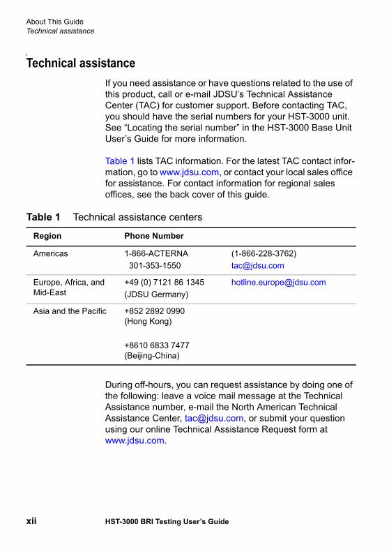
Technical assistanceIf you need assistance or have questions related to the use of this product, call or e-mail JDSU’s Technical Assistance Center (TAC) for customer support. Before contacting TAC, you should have the serial numbers for your HST-3000 unit. See “Locating the serial number” in the HST-3000 Base Unit User’s Guide for more information.
Table 1 lists TAC information. For the latest TAC contact infor-mation, go to www.jdsu.com, or contact your local sales office for assistance. For contact information for regional sales offices, see the back cover of this guide.
During off-hours, you can request assistance by doing one of the following: leave a voice mail message at the Technical Assistance number, e-mail the North American Technical Assistance Center, [email protected], or submit your question using our online Technical Assistance Request form at www.jdsu.com.
Table 1 Technical assistance centers
Region Phone Number
Americas 1-866-ACTERNA301-353-1550
(1-866-228-3762)[email protected]
Europe, Africa, and Mid-East
+49 (0) 7121 86 1345 (JDSU Germany)
Asia and the Pacific +852 2892 0990 (Hong Kong)
+8610 6833 7477 (Beijing-China)
About This GuideConventions
HST-3000 BRI Testing User’s Guide xiii
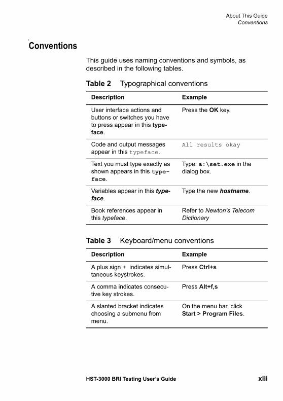
ConventionsThis guide uses naming conventions and symbols, as described in the following tables.
Table 2 Typographical conventions
Description Example
User interface actions and buttons or switches you have to press appear in this type-face.
Press the OK key.
Code and output messages appear in this typeface.
All results okay
Text you must type exactly as shown appears in this type-face.
Type: a:\set.exe in the dialog box.
Variables appear in this type-face.
Type the new hostname.
Book references appear in this typeface.
Refer to Newton’s Telecom Dictionary
Table 3 Keyboard/menu conventions
Description Example
A plus sign + indicates simul-taneous keystrokes.
Press Ctrl+s
A comma indicates consecu-tive key strokes.
Press Alt+f,s
A slanted bracket indicates choosing a submenu from menu.
On the menu bar, click Start > Program Files.
About This GuideConventions
xiv HST-3000 BRI Testing User’s Guide
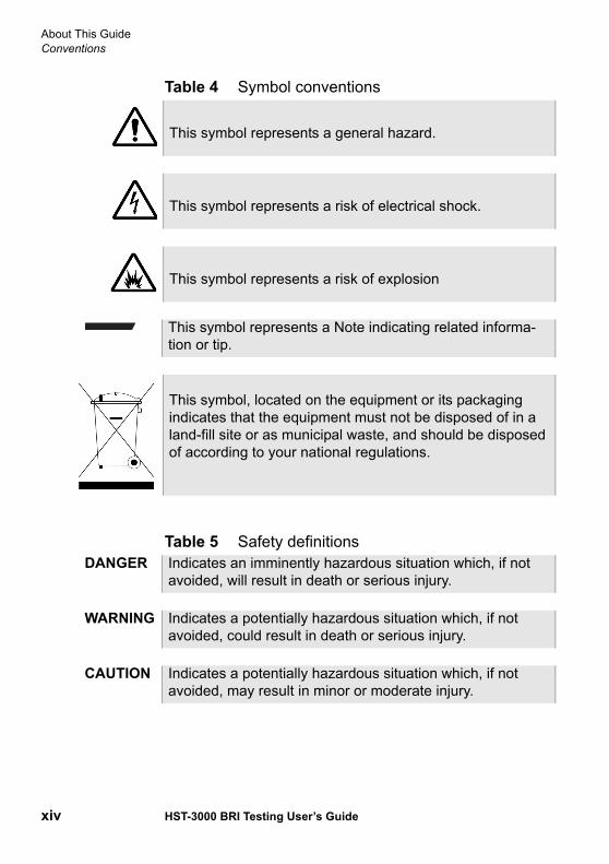
Table 4 Symbol conventions
Table 5 Safety definitions
This symbol represents a general hazard.
This symbol represents a risk of electrical shock.
This symbol represents a risk of explosion
This symbol represents a Note indicating related informa-tion or tip.
This symbol, located on the equipment or its packaging indicates that the equipment must not be disposed of in a land-fill site or as municipal waste, and should be disposed of according to your national regulations.
DANGER Indicates an imminently hazardous situation which, if not avoided, will result in death or serious injury.
WARNING Indicates a potentially hazardous situation which, if not avoided, could result in death or serious injury.
CAUTION Indicates a potentially hazardous situation which, if not avoided, may result in minor or moderate injury.
1
HST-3000 BRI Testing User’s Guide 1
Chapter 1Getting Started
This chapter provides basic information about the HST-3000 ISDN BRI testing option. Topics discussed in this chapter include the following:
– “About ISDN BRI testing” on page 2– “About BRI interfaces and the HST emulation modes” on
page 4– “Status LEDs” on page 8– “BRI connectors” on page 10– “Instrument settings and user preferences” on page 11

Chapter 1 Getting StartedAbout ISDN BRI testing
2 HST-3000 BRI Testing User’s Guide
About ISDN BRI testingThe HST-3000 ISDN BRI SIM enables you to install and main-tain ISDN BRI services. Using the HST with the BRI SIM, you can place, receive, and analyze calls, test data services using BERT analysis, test voice services using a microphone/speaker audio headset, and monitor physical (layer 1), LAPD (layer 2), and Q.931 (layer 3) results.
What’s new This release of the ISDN BRI SIM now allows you to do the following:
– Loopback 2 B channels and the D channel for analysis when emulating central office equipment in LT (line termi-nation) mode.
– Request that a device on the far end send a stream of traffic with continuous CRC errors.
– Schedule timed tests.
S/T Interfacesoftware option
If you purchase the S/T Interface software option, (part number: HST3000-ST), you can also use the ISDN BRI SIM to do the following:
– Emulate terminal equipment devices (for example, an ISDN phone or terminal adapter), and place circuit or packet calls using ISDN TE mode for the S/T interface.
– Emulate a network termination device, and passively monitor BRI service using ISDN NT1 mode for the BRI interface (S/T and U interfaces).

Chapter 1 Getting StartedAbout ISDN BRI testing
HST-3000 BRI Testing User’s Guide 3
Features andcapabilities
Using the ISDN BRI SIM, you can:
– Store frequently used numbers in a phone book, and then select a number from the phone book when placing a call.
– Place and receive up to two calls simultaneously using the standard transmit-receive interfaces. After a call is established, you can insert voice traffic into the associ-ated B Channel, or perform BERT analysis of the B Channel.
– BERT (IDSL) of the physical line.– Perform BERT analysis of two B Channels simulta-
neously.– Emulate central office equipment using Line Termination
(LT) mode.– Emulate terminal equipment devices using Terminal
Equipment (TE) mode for a U interface.– Process calls for the following switches:
– AT&T 5ESS– Nortel DMS 100– National ISDN-1 (NI-1) and National ISDN-2 (NI-2)
compliant switches– Siemens EWSD
– Monitor and analyze ISDN BRI service while the network is in-service.
– Isolate and locate problems by viewing D channel decode text for all captured transmitted and received frames when you monitor or terminate ISDN BRI service. After viewing the decode text, you can save the text to a file on the HST-3000.
– Place D channel packet calls on the U or S/T interface, and then send a FOX message to verify that the correct text is received on the far end of the circuit.

Chapter 1 Getting StartedAbout BRI interfaces and the HST emulation modes
4 HST-3000 BRI Testing User’s Guide
About BRI interfaces and the HST emulation modesThe HST ISDN BRI SIM offers six emulation modes for testing the U, S/T, and BRI interfaces. Each mode allows the HST to emulate a specific network device or devices when testing ISDN BRI service. Figure 1 illustrates the BRI interfaces.
For details on testing ISDN BRI service using the HST, refer to Chapter 2 “BRI Testing”.
Figure 1 BRI interfaces
TE1
NT1LT
LT
Channel Bank
ISDNSwitch
U InterfaceS/T InterfaceLocalLoop
BRIInterface
U LineRepeater
TE1
Chapter 1 Getting StartedAbout BRI interfaces and the HST emulation modes
HST-3000 BRI Testing User’s Guide 5
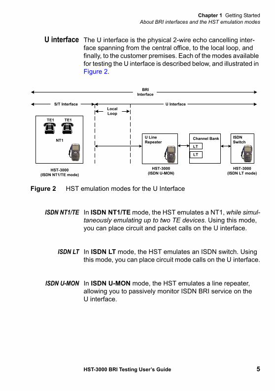
U interface The U interface is the physical 2-wire echo cancelling inter-face spanning from the central office, to the local loop, and finally, to the customer premises. Each of the modes available for testing the U interface is described below, and illustrated in Figure 2.
ISDN NT1/TE In ISDN NT1/TE mode, the HST emulates a NT1, while simul-taneously emulating up to two TE devices. Using this mode, you can place circuit and packet calls on the U interface.
ISDN LT In ISDN LT mode, the HST emulates an ISDN switch. Using this mode, you can place circuit mode calls on the U interface.
ISDN U-MON In ISDN U-MON mode, the HST emulates a line repeater, allowing you to passively monitor ISDN BRI service on the U interface.
Figure 2 HST emulation modes for the U Interface
LT
LT
Channel Bank ISDNSwitch
U InterfaceS/T InterfaceLocalLoop
BRIInterface
U LineRepeater
HST-3000(ISDN NT1/TE mode)
HST-3000(ISDN LT mode)
HST-3000(ISDN U-MON)
NT1
TE1 TE1
Chapter 1 Getting StartedAbout BRI interfaces and the HST emulation modes
6 HST-3000 BRI Testing User’s Guide
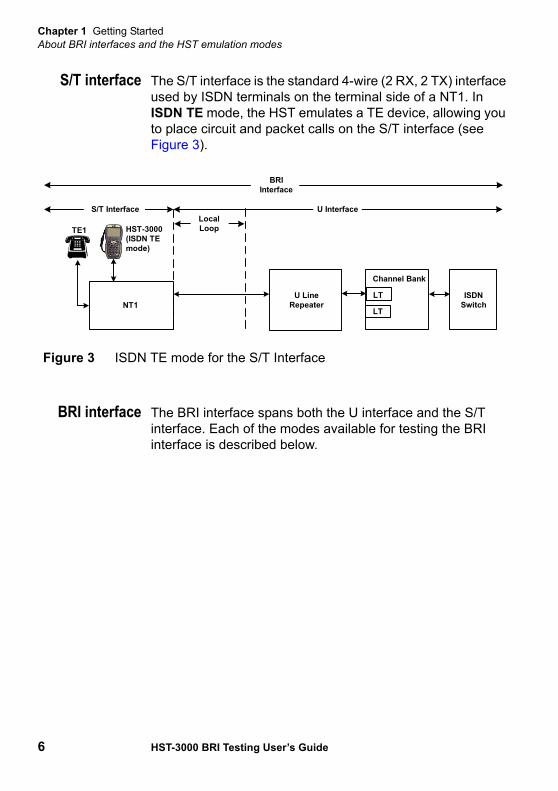
S/T interface The S/T interface is the standard 4-wire (2 RX, 2 TX) interface used by ISDN terminals on the terminal side of a NT1. In ISDN TE mode, the HST emulates a TE device, allowing you to place circuit and packet calls on the S/T interface (see Figure 3).
BRI interface The BRI interface spans both the U interface and the S/T interface. Each of the modes available for testing the BRI interface is described below.
Figure 3 ISDN TE mode for the S/T Interface
TE1
NT1LT
LT
Channel Bank
ISDNSwitch
U InterfaceS/T InterfaceLocalLoop
BRIInterface
U LineRepeater
HST-3000(ISDN TEmode)

Chapter 1 Getting StartedAbout BRI interfaces and the HST emulation modes
HST-3000 BRI Testing User’s Guide 7
ISDN NT1 In ISDN NT1 mode, the HST emulates a NT1 device, allowing you to monitor ISDN service on the entire BRI interface (see Figure 4).
BERT (IDSL) In BERT (IDSL) mode, you can configure the HST to use one of the emulation modes illustrated in Figure 5, and then BER test the physical layer.
Figure 4 ISDN NT1 emulation mode
TE1
NT1LT
LT
Channel Bank ISDNSwitch
U InterfaceS/T InterfaceLocalLoop
BRIInterface
U LineRepeater
HST-3000NT1 mode
TE1
Figure 5 HST emulation modes for BER testing the BRI Interface
TE1
NT1LT
LT
Channel Bank ISDNSwitch
U InterfaceS/T InterfaceLocalLoop
BRIInterface
U LineRepeater
HST-3000BERT (IDSL) NT
mode
HST-3000BERT (IDSL) LT
mode
HST-3000BERT(IDSL) TEmode
Chapter 1 Getting StartedStatus LEDs
8 HST-3000 BRI Testing User’s Guide
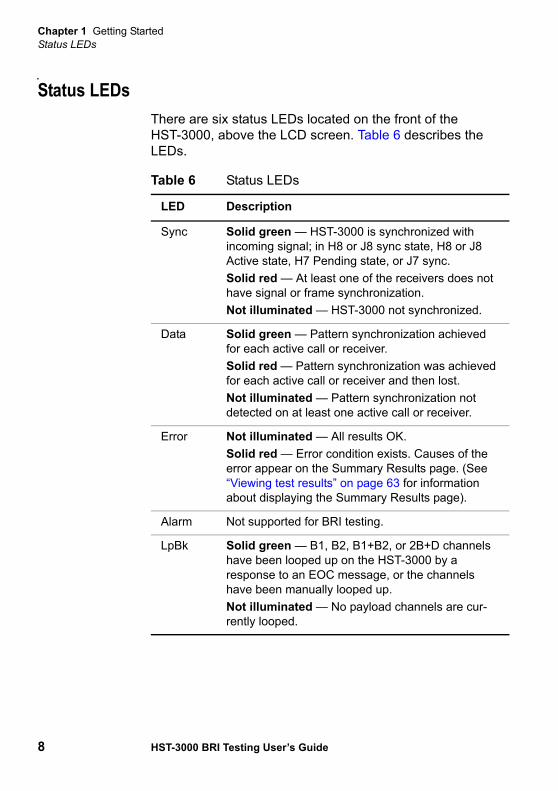
Status LEDsThere are six status LEDs located on the front of the HST-3000, above the LCD screen. Table 6 describes the LEDs.
Table 6 Status LEDs
LED Description
Sync Solid green — HST-3000 is synchronized with incoming signal; in H8 or J8 sync state, H8 or J8 Active state, H7 Pending state, or J7 sync.Solid red — At least one of the receivers does not have signal or frame synchronization.Not illuminated — HST-3000 not synchronized.
Data Solid green — Pattern synchronization achieved for each active call or receiver.Solid red — Pattern synchronization was achieved for each active call or receiver and then lost.Not illuminated — Pattern synchronization not detected on at least one active call or receiver.
Error Not illuminated — All results OK.Solid red — Error condition exists. Causes of the error appear on the Summary Results page. (See “Viewing test results” on page 63 for information about displaying the Summary Results page).
Alarm Not supported for BRI testing.
LpBk Solid green — B1, B2, B1+B2, or 2B+D channels have been looped up on the HST-3000 by a response to an EOC message, or the channels have been manually looped up.Not illuminated — No payload channels are cur-rently looped.

Chapter 1 Getting StartedStatus LEDs
HST-3000 BRI Testing User’s Guide 9
Batt Not illuminated — Battery has a useful charge.Solid green — AC adapter is plugged in.Solid red — Battery is approximately 20 percent or below of full charge.Flashing red — Approximately five minutes of use remains. Immediately attach AC adapter or replace battery. Solid amber — Battery capacity indicator (“gas gauge”) needs to be reset (see the HST-3000 Base Unit User’s Guide).
Table 6 Status LEDs (Continued)
LED Description
Chapter 1 Getting StartedBRI connectors
10 HST-3000 BRI Testing User’s Guide
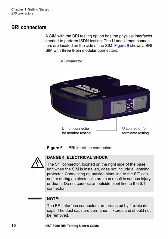
BRI connectorsA SIM with the BRI testing option has the physical interfaces needed to perform ISDN testing. The U and U mon connec-tors are located on the side of the SIM. Figure 6 shows a BRI SIM with three 8-pin modular connectors.
Figure 6 BRI interface connectors
U connector for terminate testing
U mon connector for monitor testing
S/T connector
DANGER: ELECTRICAL SHOCKThe S/T connector, located on the right side of the base unit when the SIM is installed, does not include a lightning protector. Connecting an outside plant line to the S/T con-nector during an electrical storm can result in serious injury or death. Do not connect an outside plant line to the S/T connector.
NOTE:The BRI interface connectors are protected by flexible dust caps. The dust caps are permanent fixtures and should not be removed.
Chapter 1 Getting StartedInstrument settings and user preferences
HST-3000 BRI Testing User’s Guide 11
Instrument settings and user preferencesFor information about changing instrument and preference settings, such as date and time format, port settings, sound, and screen settings, see the HST-3000 Base Unit User’s Guide.
WARNING: ELECTRICAL SHOCKElectrical shock may result in serious injury or death. Use care when connecting to telecommunications circuits, to be sure that you do not come in contact with exposed conduc-tors or power mains.
Chapter 1 Getting StartedInstrument settings and user preferences
12 HST-3000 BRI Testing User’s Guide
2
HST-3000 BRI Testing User’s Guide 13
Chapter 2BRI Testing
This chapter provides information on performing turn-up and maintenance testing using the HST-3000 BRI testing feature. Topics discussed in this chapter include the following:
– “Accessing the test configuration menus” on page 14– “Setting up the phone book” on page 14– “Placing circuit calls” on page 16– “Placing a packet call” on page 25– “Placing a self call” on page 33– “Receiving and disconnecting a call” on page 38– “Inserting voice traffic into a call” on page 41– “Performing BER analysis of calls” on page 42– “Inserting CRC or FEBE errors” on page 46– “Monitoring BRI service from the U interface” on page 47– “Emulating a NT1 on the BRI interface” on page 49– “Testing the physical layer” on page 52– “Interpreting D channel decode messages” on page 57– “Restarting tests” on page 62– “Viewing test results” on page 63

Chapter 2 BRI TestingAccessing the test configuration menus
14 HST-3000 BRI Testing User’s Guide
– “Clearing history results” on page 63
Accessing the test configuration menusThe following procedure describes how to view the menus you will use to configure the test settings.
To access the test configuration menus
1 Press the green power button to turn on the HST.It may take several seconds for the unit to power on. When a menu appears, you can continue using the unit.
2 Select the test application.
3 Press the Configure navigation key.The test configuration soft keys appear. You will use these keys to specify the settings for your test operations.
Setting up the phone bookYou can define and store frequently used phone numbers in the HST phone book, and then speed dial a number when placing a call.
To set up the HST phone book
1 If the HST is off, press the green power button to power on the unit.
Chapter 2 BRI TestingSetting up the phone book
HST-3000 BRI Testing User’s Guide 15
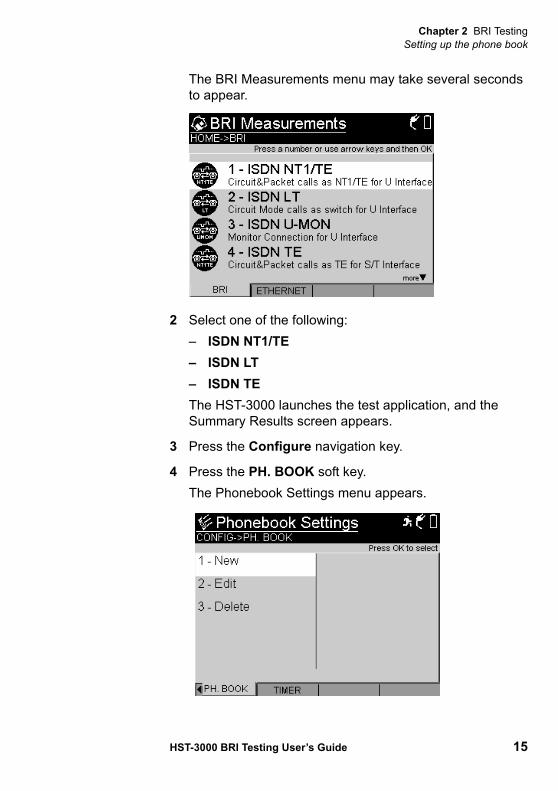
The BRI Measurements menu may take several seconds to appear.
2 Select one of the following:– ISDN NT1/TE– ISDN LT– ISDN TEThe HST-3000 launches the test application, and the Summary Results screen appears.
3 Press the Configure navigation key.
4 Press the PH. BOOK soft key.The Phonebook Settings menu appears.
Chapter 2 BRI TestingPlacing circuit calls
16 HST-3000 BRI Testing User’s Guide
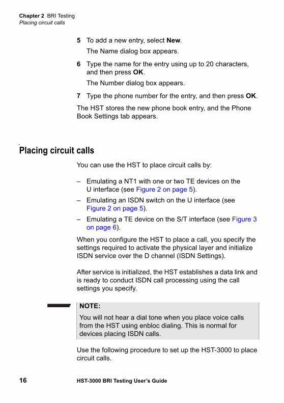
5 To add a new entry, select New.The Name dialog box appears.
6 Type the name for the entry using up to 20 characters, and then press OK.The Number dialog box appears.
7 Type the phone number for the entry, and then press OK.
The HST stores the new phone book entry, and the Phone Book Settings tab appears.
Placing circuit callsYou can use the HST to place circuit calls by:
– Emulating a NT1 with one or two TE devices on the U interface (see Figure 2 on page 5).
– Emulating an ISDN switch on the U interface (see Figure 2 on page 5).
– Emulating a TE device on the S/T interface (see Figure 3 on page 6).
When you configure the HST to place a call, you specify the settings required to activate the physical layer and initialize ISDN service over the D channel (ISDN Settings).
After service is initialized, the HST establishes a data link and is ready to conduct ISDN call processing using the call settings you specify.
Use the following procedure to set up the HST-3000 to place circuit calls.
NOTE:You will not hear a dial tone when you place voice calls from the HST using enbloc dialing. This is normal for devices placing ISDN calls.
Chapter 2 BRI TestingPlacing circuit calls
HST-3000 BRI Testing User’s Guide 17
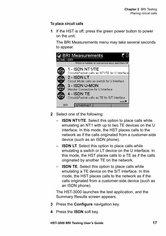
To place circuit calls
1 If the HST is off, press the green power button to power on the unit.The BRI Measurements menu may take several seconds to appear.
2 Select one of the following:– ISDN NT1/TE. Select this option to place calls while
emulating an NT1 with up to two TE devices on the U interface. In this mode, the HST places calls to the network as if the calls originated from a customer-side device (such as an ISDN phone).
– ISDN LT. Select this option to place calls while emulating a switch or LT device on the U interface. In this mode, the HST places calls to a TE as if the calls originated by another TE on the network.
– ISDN TE. Select this option to place calls while emulating a TE device on the S/T interface. In this mode, the HST places calls to the network as if the calls originated from a customer-side device (such as an ISDN phone).
The HST-3000 launches the test application, and the Summary Results screen appears.
3 Press the Configure navigation key.
4 Press the ISDN soft key.

Chapter 2 BRI TestingPlacing circuit calls
18 HST-3000 BRI Testing User’s Guide
The ISDN settings menu appears.
5 Press the number key for the ISDN setting you want to configure. You can also use the arrow keys to select the setting you want to change, and then press the OK key. Press the Cancel key to exit a menu.The table below describes the settings.
Setting Parameters
Loop Address Address on the NT device used for loop-ing. (Available in LT mode only.)
EOC message Code for looping an NT device. Table 26 on page 103 lists the available codes. (Available in LT mode only.)
Call Control Type of switch protocol.– National — Selects National ISDN-2
(NI-2) as the switch protocol– 5ESSMP– 5ESSPP– DMSFNOTE: The majority of ISDN providers use the National switch protocol. 5ESS and DMS are typically used by providers who have a custom or proprietary method for implementing ISDN.

Chapter 2 BRI TestingPlacing circuit calls
HST-3000 BRI Testing User’s Guide 19
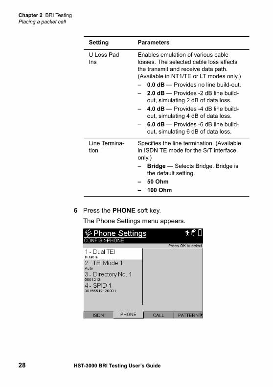
6 Press the PHONE soft key.The Phone Settings menu appears.
Dual Call – Disable — Allows one call.– Enable — Allows two independent
calls.
U Loss Pad Ins
Enables emulation of various cable losses. The selected cable loss affects the transmit and receive data path. (Available in NT1/TE or LT modes only.)– 0 dB — Provides no line build-out.– 2 dB — Provides -2 dB line build-out,
simulating 2 dB of data loss.– 4 dB — Provides -4 dB line build-out,
simulating 4 dB of data loss.– 6 dB — Provides -6 dB line build-out,
simulating 6 dB of data loss.
Line Termina-tion
Specifies the line termination. (Available in TE or NT1 mode for the S/T interface only.)– Bridge — Selects Bridge. Bridge is
the default setting.– 50 Ohm– 100 Ohm
Setting Parameters

Chapter 2 BRI TestingPlacing circuit calls
20 HST-3000 BRI Testing User’s Guide
7 Select, and then define each of the following settings:
8 Press the CALL soft key.
Setting Parameters
Dual TEI Allows the HST to simulate one of two independent terminal endpoint identifiers: Enable or Disable. Enable is only avail-able if Dual Call is enabled on the ISDN Settings menu (see page 19). If you enable Dual TEI, the TEI Mode 2, Direc-tory No. 2, and SPID 2 fields appear.
TEI Mode 1 Method of determining the terminal end-point identifier: Auto or Fixed. If you enable Dual TEI, the TEI Mode 2 field also appears.
TEI 1 Value for the terminal endpoint identifier. (Available only if TEI Mode 1 is Fixed.)
Directory No. 1 Number used to identify the line for the outgoing call. This is the caller ID of the call placed from the HST. If you enable Dual TEI, the Directory No. 2 field also appears.
SPID 1 ID number of the service profile you want to emulate. (Available only in NT1/TE mode.) If you enable Dual TEI, the SPID 2 field also appears.
Chapter 2 BRI TestingPlacing circuit calls
HST-3000 BRI Testing User’s Guide 21
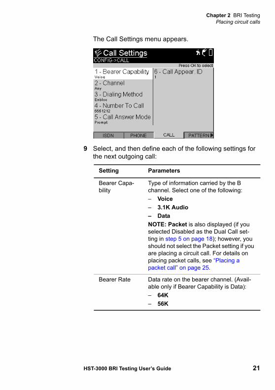
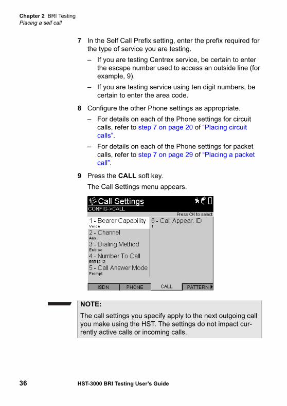
The Call Settings menu appears.
9 Select, and then define each of the following settings for the next outgoing call:
Setting Parameters
Bearer Capa-bility
Type of information carried by the B channel. Select one of the following:– Voice– 3.1K Audio– DataNOTE: Packet is also displayed (if you selected Disabled as the Dual Call set-ting in step 5 on page 18); however, you should not select the Packet setting if you are placing a circuit call. For details on placing packet calls, see “Placing a packet call” on page 25.
Bearer Rate Data rate on the bearer channel. (Avail-able only if Bearer Capability is Data):– 64K– 56K
Chapter 2 BRI TestingPlacing circuit calls
22 HST-3000 BRI Testing User’s Guide
Channel Channel on which to place the call. (Available only if Bearer Capability is Voice, 3.1K Audio, or Data).– Any– B1– B2
Dialing Method Method by which the HST-3000 places the call.– Overlap — You type the phone num-
ber during the test.– Enbloc — HST-3000 sends the
phone number you specify in the Number to Call field.
Number to Call Phone number you want to dial. Enter up to 30 digits, *, and #.
Call Answer Mode
Method by which HST-300 answers incoming calls.– Prompt — Prompts to accept, reject,
or ignore each incoming call as it comes in. If you ignore a call, you can answer or reject the call later.
– Accept — Automatically accepts up to 2 incoming calls, and then rejects any additional calls. You can always check the Summary Results screen to see if a call is active on the HST.
– Reject — Automatically rejects all incoming calls.
Setting Parameters

Chapter 2 BRI TestingPlacing circuit calls
HST-3000 BRI Testing User’s Guide 23
10 Do the following:– Connect the U connector to the CO (network) side of
the line.– If you selected ISDN TE in step 2, connect the S/T
connector to the S/T interface.
11 Verify that the Sync LED is illuminated to ensure that the HST is synchronized with a valid signal.
12 Verify the link is up by doing the following:
a Press the Home navigation key.
b Press the Display soft key, and then select LED.
c Verify the Active LED is on.
d Verify the TEI 1 Ready LED is on.
13 Press the Action soft key, and then select Send Auto SPID 1 to request a list of available SPIDs from the switch.
Call Appear ID Appearance ID included in the call header.– If you are using NATIONAL or DMSF
call control, enter a number ranging from 1 to 255, or press the None soft-key.
– If you are using 5ESSMP or 5ESSPP call control, enter a number ranging from 1 to 255, or press the Auto soft-key.
Setting Parameters
NOTE:The call settings you specify apply to the next outgoing call you make using the HST. The settings do not impact cur-rently active calls or incoming calls.
Chapter 2 BRI TestingPlacing circuit calls
24 HST-3000 BRI Testing User’s Guide
The HST then assigns the first available SPID or SPIDs to the call.
14 Optional. If you specified National as the Call Control in step 5 on page 18, and you would like to download addi-tional call parameters from the poll switch, do the following:
a Press the Action soft key, and then select Poll Switch 1.
b Press the Display soft key, and then select the ISDN result category.The PD Status result displays each of the following status results in succession:Polling Switch — Indicates that the HST is establishing communication with the polling switch. If the HST does not receive a response from the switch within two seconds, the PD Status result changes to PD No Response.
Collecting Data — Indicates that the HST is collecting data from the polling switch.
Results Ready — Indicates that data collection is complete.
The PD Display result then displays the lines of decoded parameter download data.
15 Press the Action soft key, and then do one of the following:– If you specified a number to call in step 9, select Dial
Call 1.– If you want to speed dial a number from the HST
phone book, select Speed Dial (Call 1).The Speed-Dial List appears, listing each of the entries you defined in the phone book. Press the number key for the entry you want to speed dial, or use the arrow keys to select the entry, and then press OK.
16 Verify that the call status is CONNECTED on the Summary Results, Call 1 Results, or Call 2 Results screen.
Chapter 2 BRI TestingPlacing a packet call
HST-3000 BRI Testing User’s Guide 25
17 If you want to place a second call, do the following:
a Ensure you selected Enabled for the Dual Call setting in step 5 on page 18.
b Repeat steps 6-16 starting on page 19.
c Press the Action soft key, and then select Send Auto SPID 2 to request a list of available SPIDs from the switch. The HST then assigns the first available SPID or SPIDs to the call.
d Press the Action soft key, and then select Dial Call 2, or Speed Dial (Call 2).
You have placed ISDN BRI circuit calls.
Placing a packet callYou can use the HST to place packet calls on the D channel by:
– Emulating a NT1 with one or two TE devices on the U interface (see Figure 2 on page 5).
– Emulating a TE device on the S/T interface (see Figure 3 on page 6).
When you configure the HST to place a packet call, you specify the settings required to activate the physical layer and initialize ISDN service over the D channel (ISDN Settings).
After service is initialized, the HST establishes a data link, and you can transmit an ASCII FOX message using the Send Fox action.
NOTE:If the call status is not CONNECTED, you can view the cause code (indicating the reason the call was not connected) on the Call 1 Results or Call 2 Results screen.
Chapter 2 BRI TestingPlacing a packet call
26 HST-3000 BRI Testing User’s Guide
Use the following procedure to set up the HST-3000 to place packet calls.
To place packet calls on the D channel
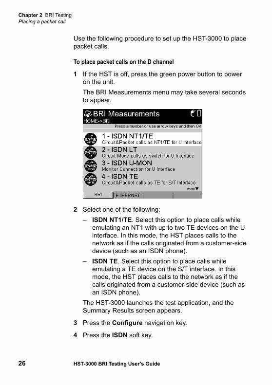
1 If the HST is off, press the green power button to power on the unit.The BRI Measurements menu may take several seconds to appear.
2 Select one of the following:– ISDN NT1/TE. Select this option to place calls while
emulating an NT1 with up to two TE devices on the U interface. In this mode, the HST places calls to the network as if the calls originated from a customer-side device (such as an ISDN phone).
– ISDN TE. Select this option to place calls while emulating a TE device on the S/T interface. In this mode, the HST places calls to the network as if the calls originated from a customer-side device (such as an ISDN phone).
The HST-3000 launches the test application, and the Summary Results screen appears.
3 Press the Configure navigation key.
4 Press the ISDN soft key.
Chapter 2 BRI TestingPlacing a packet call
HST-3000 BRI Testing User’s Guide 27
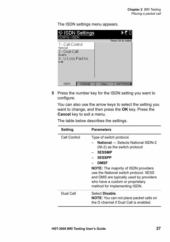
The ISDN settings menu appears.
5 Press the number key for the ISDN setting you want to configure. You can also use the arrow keys to select the setting you want to change, and then press the OK key. Press the Cancel key to exit a menu.The table below describes the settings.
Setting Parameters
Call Control Type of switch protocol.– National — Selects National ISDN-2
(NI-2) as the switch protocol– 5ESSMP– 5ESSPP– DMSFNOTE: The majority of ISDN providers use the National switch protocol. 5ESS and DMS are typically used by providers who have a custom or proprietary method for implementing ISDN.
Dual Call Select Disable.NOTE: You can not place packet calls on the D channel if Dual Call is enabled.
Chapter 2 BRI TestingPlacing a packet call
28 HST-3000 BRI Testing User’s Guide
6 Press the PHONE soft key.The Phone Settings menu appears.
U Loss Pad Ins
Enables emulation of various cable losses. The selected cable loss affects the transmit and receive data path. (Available in NT1/TE or LT modes only.)– 0.0 dB — Provides no line build-out.– 2.0 dB — Provides -2 dB line build-
out, simulating 2 dB of data loss.– 4.0 dB — Provides -4 dB line build-
out, simulating 4 dB of data loss.– 6.0 dB — Provides -6 dB line build-
out, simulating 6 dB of data loss.
Line Termina-tion
Specifies the line termination. (Available in ISDN TE mode for the S/T interface only.)– Bridge — Selects Bridge. Bridge is
the default setting.– 50 Ohm– 100 Ohm
Setting Parameters
Chapter 2 BRI TestingPlacing a packet call
HST-3000 BRI Testing User’s Guide 29
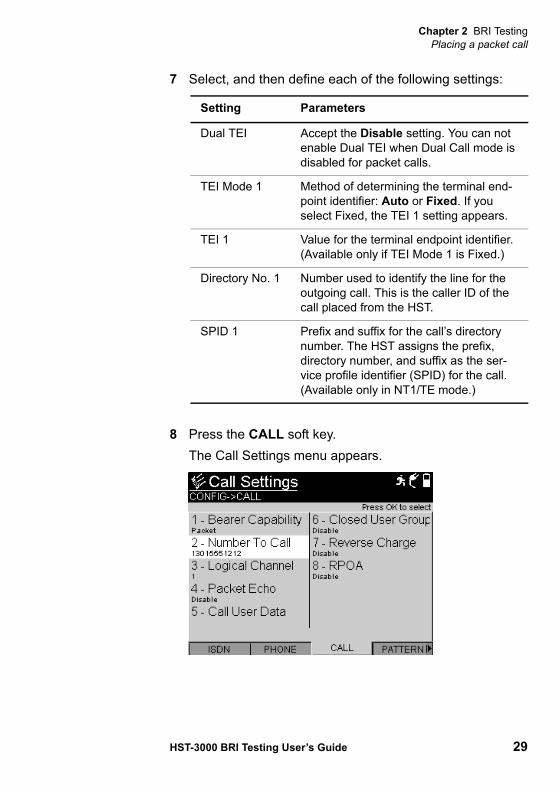
7 Select, and then define each of the following settings:
8 Press the CALL soft key.The Call Settings menu appears.
Setting Parameters
Dual TEI Accept the Disable setting. You can not enable Dual TEI when Dual Call mode is disabled for packet calls.
TEI Mode 1 Method of determining the terminal end-point identifier: Auto or Fixed. If you select Fixed, the TEI 1 setting appears.
TEI 1 Value for the terminal endpoint identifier. (Available only if TEI Mode 1 is Fixed.)
Directory No. 1 Number used to identify the line for the outgoing call. This is the caller ID of the call placed from the HST.
SPID 1 Prefix and suffix for the call’s directory number. The HST assigns the prefix, directory number, and suffix as the ser-vice profile identifier (SPID) for the call. (Available only in NT1/TE mode.)
Chapter 2 BRI TestingPlacing a packet call
30 HST-3000 BRI Testing User’s Guide
9 Select, and then define each of the following settings for the next outgoing call:
Setting Parameters
Bearer Capa-bility
Select Packet.
Number to Call Phone number you want to dial. Enter up to 30 digits, *, and #.
Logical Chan-nel
Logical channel on the D channel to place the call on (0 through 15).
Packet Echo Select one of the following:– Enable. The HST will transmit
received packets back to the origina-tor.
– Disable. Packet Echo is disabled by default.
Call User Data If you want to identify the data the HST is transmitting with a specific user or call:– Select the setting to display the Call
User Data dialog box.– Type identifying text into the field pro-
vided. – Select OK to store the call user data,
and return to the Call Settings menu.The Call User Data is disabled by default.
Closed User Group
If you want to secure the connection because you are testing circuits to ATMS or point-of-sales terminals:– Select the setting to display the
Closed User Group dialog box.– Type the password for the circuit,
ranging from 0-9999.– Select OK to store the password, and
return to the Call Settings menu.The Closed User Group password is dis-abled by default.
Chapter 2 BRI TestingPlacing a packet call
HST-3000 BRI Testing User’s Guide 31
10 Do the following:– Connect the U connector to the CO (network) side of
the line.– If you selected ISDN TE in step 2, connect the S/T
connector to the S/T interface.
11 Verify that the Sync LED is illuminated to ensure that the HST is synchronized with a valid signal.
12 Verify the link is up by doing the following:
a Press the Home navigation key.
b Press the Display soft key, and then select LED.
c Verify the Active LED is on.
d Verify the TEI 1 Ready LED is on.
13 Press Restart to clear any errors.
Reverse Charge
If you want to place collect packet calls, select Enable.The Reverse Charge setting is disabled by default.
RPOA If you want to specify a prefix to identify the ISDN’s Recognized Private Operat-ing Agency (RPOA) do this:– Select the setting to display the
RPOA dialog box.– Type the setting for the circuit, rang-
ing from 0-9999.– Select OK to store the setting, and
return to the Call Settings menu.The RPOA setting is disabled by default.NOTE: For ISDN X.25, the RPOA is usu-ally the data network identification code (DNIC) for the ISDN’s long distance car-rier.
Setting Parameters
Chapter 2 BRI TestingPlacing a packet call
32 HST-3000 BRI Testing User’s Guide
14 Press the Action soft key, and then do one of the following:– If you specified a number to call in step 9, select Dial
Call 1.– If you want to speed dial a number from the HST
phone book, select Speed Dial (Call 1).The Speed-Dial List appears, listing each of the entries you defined in the phone book. Press the number key for the entry you want to speed dial, or use the arrow keys to select the entry, and then press OK.
15 Verify that the call status is CONNECTED on the Summary Results, Call 1 Results, or Call 2 Results screen.
16 Press the Action soft key, and then select the Send FOX action to transmit the ASCII FOX text to the loopback port or test device on the far end of the circuit.
NOTE:If the call status is not CONNECTED, you can view the cause code (indicating the reason the call was not connected) on the Call 1 Results or Call 2 Results screen.
Chapter 2 BRI TestingPlacing a self call
HST-3000 BRI Testing User’s Guide 33
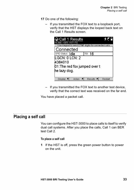
17 Do one of the following:– If you transmitted the FOX text to a loopback port,
verify that the HST displays the looped back text on the Call 1 Results screen.
– If you transmitted the FOX text to another test device, verify that the correct text was received on the far end.
You have placed a packet call.
Placing a self callYou can configure the HST-3000 to place calls to itself to verify dual call systems. After you place the calls, Call 1 can BER test Call 2.
To place a self call
1 If the HST is off, press the green power button to power on the unit.
Chapter 2 BRI TestingPlacing a self call
34 HST-3000 BRI Testing User’s Guide
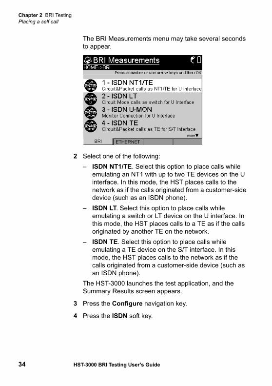
The BRI Measurements menu may take several seconds to appear.
2 Select one of the following:– ISDN NT1/TE. Select this option to place calls while
emulating an NT1 with up to two TE devices on the U interface. In this mode, the HST places calls to the network as if the calls originated from a customer-side device (such as an ISDN phone).
– ISDN LT. Select this option to place calls while emulating a switch or LT device on the U interface. In this mode, the HST places calls to a TE as if the calls originated by another TE on the network.
– ISDN TE. Select this option to place calls while emulating a TE device on the S/T interface. In this mode, the HST places calls to the network as if the calls originated from a customer-side device (such as an ISDN phone).
The HST-3000 launches the test application, and the Summary Results screen appears.
3 Press the Configure navigation key.
4 Press the ISDN soft key.
Chapter 2 BRI TestingPlacing a self call
HST-3000 BRI Testing User’s Guide 35
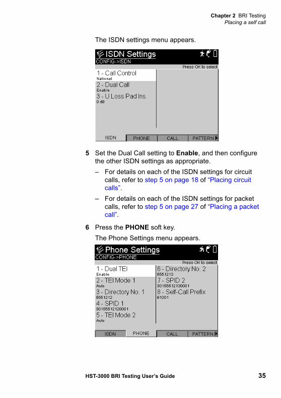
The ISDN settings menu appears.
5 Set the Dual Call setting to Enable, and then configure the other ISDN settings as appropriate. – For details on each of the ISDN settings for circuit
calls, refer to step 5 on page 18 of “Placing circuit calls”.
– For details on each of the ISDN settings for packet calls, refer to step 5 on page 27 of “Placing a packet call”.
6 Press the PHONE soft key.The Phone Settings menu appears.
Chapter 2 BRI TestingPlacing a self call
36 HST-3000 BRI Testing User’s Guide
7 In the Self Call Prefix setting, enter the prefix required for the type of service you are testing.– If you are testing Centrex service, be certain to enter
the escape number used to access an outside line (for example, 9).
– If you are testing service using ten digit numbers, be certain to enter the area code.
8 Configure the other Phone settings as appropriate. – For details on each of the Phone settings for circuit
calls, refer to step 7 on page 20 of “Placing circuit calls”.
– For details on each of the Phone settings for packet calls, refer to step 7 on page 29 of “Placing a packet call”.
9 Press the CALL soft key.The Call Settings menu appears.
NOTE:The call settings you specify apply to the next outgoing call you make using the HST. The settings do not impact cur-rently active calls or incoming calls.
Chapter 2 BRI TestingPlacing a self call
HST-3000 BRI Testing User’s Guide 37
10 Configure the Call settings as appropriate. – For details on each of the Call settings for circuit calls,
refer to step 9 on page 21 of “Placing circuit calls”.– For details on each of the Call settings for packet calls,
refer to step 9 on page 30 of “Placing a packet call”.
11 Select the BER pattern, and if you plan on inserting errors, configure the error settings (see step 3-4 on page 43 of “Performing BER analysis of calls”).
12 Do the following:– Connect the U connector to the CO (network) side of
the line.– If you selected ISDN TE in step 2, connect the S/T
connector to the S/T interface.
13 Verify that the Sync LED is illuminated to ensure that the HST is synchronized with a valid signal.
14 Verify the link is up by doing the following:
a Press the Home navigation key.
b Press the Display soft key, and then select LED.
c Verify the Active LED is on.
d Verify the TEI 1 Ready LED is on.
15 Press the Action soft key, and then select Self-Call BERT.
16 Verify that the call status is CONNECTED on the Summary Results, Call 1 Results, and Call 2 Results screen.
You have placed a self call, and Call 1 is BER testing Call 2.
NOTE:If the call status is not CONNECTED, you can view the cause code (indicating the reason the call was not connected) on the Call 1 Results or Call 2 Results screen.
Chapter 2 BRI TestingReceiving and disconnecting a call
38 HST-3000 BRI Testing User’s Guide
Receiving and disconnecting a callIf you set up the HST-3000 to prompt you whenever a call comes into the unit, a popup dialog box appears on the current results screen prompting you to accept, reject, or ignore each incoming call. If you choose to ignore a call, you can accept or reject it later using the Answer Call or Discon-nect Call action (available using the Action soft key).
Accepting a call You can accept up to two calls on the HST. When you accept a call, the call automatically connects to the microphone, and the payload is dropped to the speaker. If you are using a headset, the call connects to the headset, and the payload is dropped to the headset speaker.
When you accept a second call, it remains in an idle state. To drop its payload to the speaker, press the Action soft key, and then select Audio Call 2.
You can insert voice traffic into the B channel associated with the call by speaking into the microphone or headset (see “Inserting voice traffic into a call” on page 41), or you can insert BER test patterns (see “Performing BER analysis of calls” on page 42).
To accept a call when prompted– Press OK.
To accept a call using the Action soft key
1 Display the Summary Results screen, and then verify that a call is coming into the unit.
2 Press the Action soft key, and then select Answer Call 1 or Answer Call 2.
The HST-3000 accepts the call.
Chapter 2 BRI TestingReceiving and disconnecting a call
HST-3000 BRI Testing User’s Guide 39
Rejecting a call When you reject a call, the HST-3000 disconnects the call.
To reject a call when prompted– Press Cancel.
To reject a call using the Action soft key
1 Display the Summary Results screen, and then verify that a call is coming into the unit.
2 Press the Action soft key, and then choose Disconnect Call 1 or Disconnect Call 2.
The HST-3000 rejects the call.
Ignoring a call When you ignore a call, the HST-3000 closes the dialog box, but keeps the incoming call alive so you can choose to answer or reject it later using the Action soft key.
To ignore a call when prompted– Press the up arrow button to select Ignore.
The HST-3000 ignores the call.
Disconnectinga call
To disconnect a call
1 Press the Action soft key, and then select Disconnect Call 1 or Disconnect Call 2.
2 Verify that the call status is DISCONNECTED on the Summary Results, Call 1 Results, or Call 2 Results screen.
NOTE:If the call status is not DISCONNECTED, you can view the cause code (indicating the reason the call was not discon-nected) on the Call 1 Results or Call 2 Results screen. See “Q.931 Cause Values” on page 90 for descriptions of each code.
Chapter 2 BRI TestingReceiving and disconnecting a call
40 HST-3000 BRI Testing User’s Guide
TransmittingDTMF tones
After a call's channel is assigned, you can display the Call 1 or Call 2 Results screen, and then use the keypad to insert and transmit DTMF tones.
When you transmit DTMF tones, the HST temporarily disables the microphone.
To transmit DTMF tones
1 Place a call (see “Placing circuit calls” on page 16).
2 Press the Display soft key, and then select Call 1 or Call 2.
3 Select the Action soft key, and then choose Audio Call 1 or Audio Call 2 to connect the call to the audio and speaker.
4 Enter the DTMF tones using the keypad.
The HST transmits the tones.
Completing acall with
overlap dialing
Using overlap dialing, you manually complete a call after connecting to the switch.
To complete a call using overlap dialing
1 Place a call (see “Placing circuit calls” on page 16).In step 9 of that procedure, select Overlap as the Dialing Method.
2 Press the Action soft key, and then select Dial Call 1 or Dial Call 2.
3 Type the number using the keypad.
When the LT device recognizes the number, CONNECTED appears on the display.
Chapter 2 BRI TestingInserting voice traffic into a call
HST-3000 BRI Testing User’s Guide 41
Inserting voice traffic into a callWhen you place or receive a voice call using the HST, you can use the microphone on the HST or a headset to insert voice traffic into the call’s B channel.
To insert voice traffic into a call
1 If you are using an audio headset, connect the headset to the headset connector on the top panel of the HST.
2 Do one of the following:– If you are placing a call, specify the ISDN and call
settings for the call (see “Placing circuit calls” on page 16).
– If you are receiving a call, accept the call (see “Accepting a call” on page 38).
3 Verify that the call is connected on the Summary Results, Call 1 Results, or Call 2 Results screen. The call status must be CONNECTED.
4 If you are not analyzing voice traffic on another call, the HST automatically connects the call to the speaker and microphone or the headset.If you are currently BER testing or idling another call, and if Audio Call 1 and Audio Call 2 are not activated, select the Action soft key, and then choose Audio Call 1 or Audio Call 2 to connect the call to the speaker and micro-phone or the headset.
5 Speak into the microphone or the headset.
NOTE:If the call status is not CONNECTED, you can view the cause code (indicating the reason the call was not connected) on the Call 1 Results or Call 2 Results screen.
Chapter 2 BRI TestingPerforming BER analysis of calls
42 HST-3000 BRI Testing User’s Guide
Voice traffic is inserted into the call.
Performing BER analysis of callsWhen you place or receive calls in NT1/TE, LT, or TE mode, you can perform BER analysis of the associated B channels. In addition to providing general ISDN results, the HST provides statistics collected on the D channel and results based on the BER analysis of the B channels.
To BER test B channels for connected calls
1 Do one of the following:– If you are placing a call, specify the ISDN and Call
settings for the B channel (see “Placing circuit calls” on page 16).
– If you are receiving a call, accept the call (see “Accepting a call” on page 38).
2 Press the Configure navigation key.
3 Press the PATTERN soft key, and then specify the pattern to insert into the B channels (see “BERT patterns” on page 100 for a complete list of available patterns).
NOTE:You can only insert voice traffic into a single call at a time. If two calls are active, you can stop transmitting voice traffic on one call using the IDLE Call 1 or IDLE Call 2 action, and then insert voice traffic on the other call. The idle call remains active, allowing you to insert voice traffic at a later time, or perform BERT analysis of the call’s B channel.
NOTE:When you BER test two connected calls simultaneously, the HST uses the same BER pattern for each call; however, you can specify different error insertion settings for each individual call.
Chapter 2 BRI TestingPerforming BER analysis of calls
HST-3000 BRI Testing User’s Guide 43
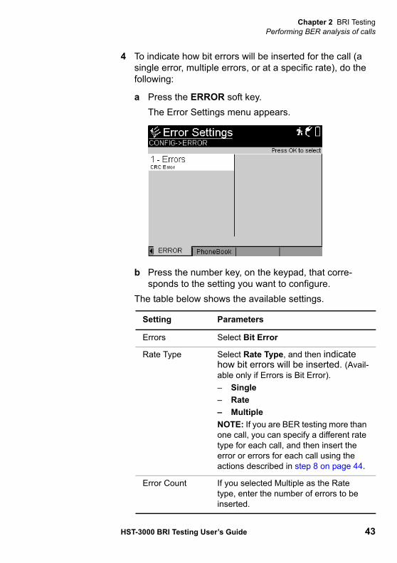
4 To indicate how bit errors will be inserted for the call (a single error, multiple errors, or at a specific rate), do the following:
a Press the ERROR soft key.The Error Settings menu appears.
b Press the number key, on the keypad, that corre-sponds to the setting you want to configure.
The table below shows the available settings.
Setting Parameters
Errors Select Bit Error
Rate Type Select Rate Type, and then indicate how bit errors will be inserted. (Avail-able only if Errors is Bit Error).– Single– Rate – MultipleNOTE: If you are BER testing more than one call, you can specify a different rate type for each call, and then insert the error or errors for each call using the actions described in step 8 on page 44.
Error Count If you selected Multiple as the Rate type, enter the number of errors to be inserted.
Chapter 2 BRI TestingPerforming BER analysis of calls
44 HST-3000 BRI Testing User’s Guide
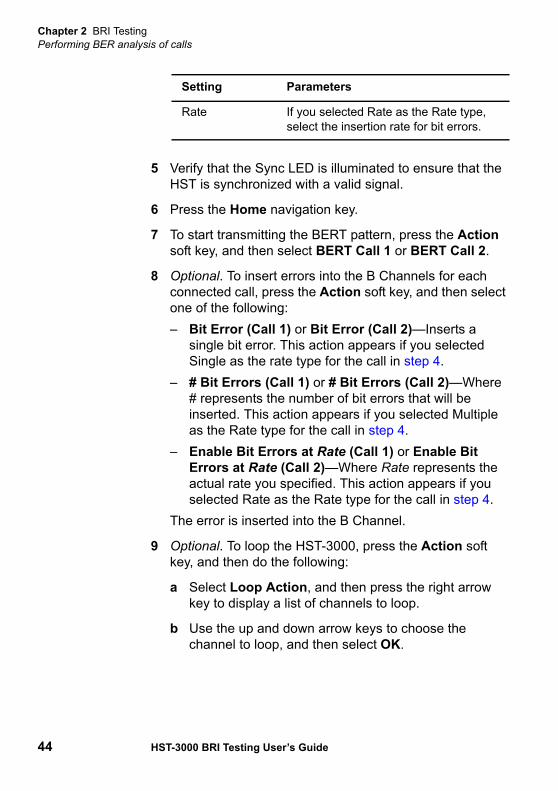
5 Verify that the Sync LED is illuminated to ensure that the HST is synchronized with a valid signal.
6 Press the Home navigation key.
7 To start transmitting the BERT pattern, press the Action soft key, and then select BERT Call 1 or BERT Call 2.
8 Optional. To insert errors into the B Channels for each connected call, press the Action soft key, and then select one of the following:– Bit Error (Call 1) or Bit Error (Call 2)—Inserts a
single bit error. This action appears if you selected Single as the rate type for the call in step 4.
– # Bit Errors (Call 1) or # Bit Errors (Call 2)—Where# represents the number of bit errors that will be inserted. This action appears if you selected Multiple as the Rate type for the call in step 4.
– Enable Bit Errors at Rate (Call 1) or Enable Bit Errors at Rate (Call 2)—Where Rate represents the actual rate you specified. This action appears if you selected Rate as the Rate type for the call in step 4.
The error is inserted into the B Channel.
9 Optional. To loop the HST-3000, press the Action soft key, and then do the following:
a Select Loop Action, and then press the right arrow key to display a list of channels to loop.
b Use the up and down arrow keys to choose the channel to loop, and then select OK.
Rate If you selected Rate as the Rate type, select the insertion rate for bit errors.
Setting Parameters
Chapter 2 BRI TestingPerforming BER analysis of calls
HST-3000 BRI Testing User’s Guide 45
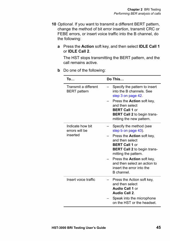
10 Optional. If you want to transmit a different BERT pattern, change the method of bit error insertion, transmit CRC or FEBE errors, or insert voice traffic into the B channel, do the following:
a Press the Action soft key, and then select IDLE Call 1 or IDLE Call 2.The HST stops transmitting the BERT pattern, and the call remains active.
b Do one of the following:
To… Do This…
Transmit a different BERT pattern
– Specify the pattern to insert into the B channels. See step 3 on page 42.
– Press the Action soft key, and then select BERT Call 1 or BERT Call 2 to begin trans-mitting the new pattern.
Indicate how bit errors will be inserted
– Specify the method (see step b on page 43).
– Press the Action soft key, and then select BERT Call 1 or BERT Call 2 to begin trans-mitting the pattern.
– Press the Action soft key, and then select an action to insert the error into the B channel.
Insert voice traffic – Press the Action soft key, and then select Audio Call 1 or Audio Call 2.
– Speak into the microphone on the HST or the headset.

Chapter 2 BRI TestingInserting CRC or FEBE errors
46 HST-3000 BRI Testing User’s Guide
11 To disconnect the call, press the Action soft key, and then select Disconnect Call 1 or Disconnect Call 2.
BERT analysis of the call is complete.
Inserting CRC or FEBE errorsIn LT mode, you can insert a continuous stream of CRC or FEBE errors into the BRI U interface.
To insert CRC or FEBE errors
1 If the HST is off, press the green power button to power on the unit.The BRI Measurements menu may take several seconds to appear.
2 Select ISDN LT.The HST-3000 starts the test.
3 Press the Configure navigation key.
4 Press the ISDN soft key, and then specify the ISDN settings (see step 4 and step 5 on page 18 of “Placing circuit calls”).
5 Press the ERROR soft key.
Insert CRC or FEBE errors
– Specify CRC or FEBE as the error type (on the Error Settings menu).
– Press the Action soft key, and then select an action to insert the errors into the B channel.
To… Do This…

Chapter 2 BRI TestingMonitoring BRI service from the U interface
HST-3000 BRI Testing User’s Guide 47
The Error Settings menu appears.
6 Specify CRC or FEBE as the Errors setting.
7 Connect the U connector to the CO (network) side of the line.
8 Press the Home navigation key to display results.
9 To insert errors into the BRI U interface, press the Action soft key, and then select one of the following:– Enable CRC Error—Inserts a continuous stream of
CRC errors. This action appears if you selected CRC Error as the error type in step 6.
– Enable FEBE Error—Inserts a continuous stream of FEBE errors. This action appears if you selected FEBE Error as the error type in step 6.
The errors are inserted into the BRI U interface.
Monitoring BRI service from the U interfaceThe HST-3000 allows you to monitor and analyze ISDN BRI service from the U interface while the network is in-service. During the test, the HST emulates a repeater, and monitors all D channel frames present. It then decodes the received D channel information.

Chapter 2 BRI TestingMonitoring BRI service from the U interface
48 HST-3000 BRI Testing User’s Guide
To monitor ISDN BRI service from the U interface
1 If the HST is off, press the green power button to power on the unit.The BRI Measurements menu may take several seconds to appear.
2 Select ISDN U-MON.The HST-3000 starts the monitor test.
3 Optional. To specify the switch protocol (call control) or clock source the HST uses while emulating a repeater, press the Configure navigation key, and then specify the following settings:
Setting Parameters
Call Control Type of switch protocol.– National — Selects National ISDN-2
(NI-2) as the switch protocol. National is the default setting.
– 5ESSMP– 5ESSPP– DMSF
Clock Source – Internal– External

Chapter 2 BRI TestingEmulating a NT1 on the BRI interface
HST-3000 BRI Testing User’s Guide 49
4 Connect the U connector to the CO (network) side of the line.
5 Connect the U mon connector to the CPE (customer) side of the line.
6 Press the Home navigation key, and then press the Restart soft key to clear all alarms and begin the test.
7 Press the Display soft key, and then select D-Chan Decode.D-channel decode messages appear in the Decode results category. For information about interpreting these messages, see “Interpreting D channel decode messages” on page 57.
8 To stop a running test, press the Cancel key.
You have finished monitoring BRI service from the U interface.
Emulating a NT1 on the BRI interfaceThe HST-3000 allows you to monitor and analyze BRI service from the U and S/T interface while the network is in-service. During the test, the HST emulates an NT1 device and moni-tors all D channel frames present. It then decodes the received D channel information.
To monitor BRI service from the BRI interface
1 If the HST is off, press the green power button to power on the unit.
NOTE:When repeater power is present, the total nominal voltage drop from the U connector to the U mon connector, and from the U mon connector to the U connector, is 11 volts.
Chapter 2 BRI TestingEmulating a NT1 on the BRI interface
50 HST-3000 BRI Testing User’s Guide
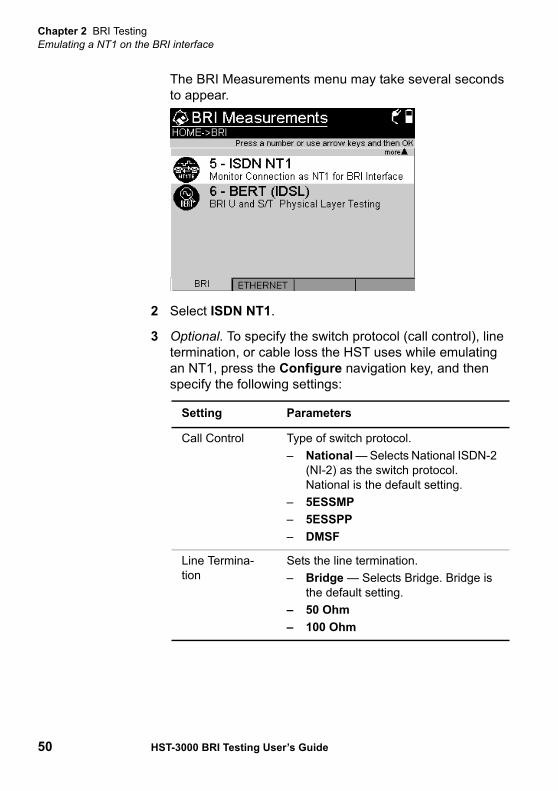
The BRI Measurements menu may take several seconds to appear.
2 Select ISDN NT1.
3 Optional. To specify the switch protocol (call control), line termination, or cable loss the HST uses while emulating an NT1, press the Configure navigation key, and then specify the following settings:
Setting Parameters
Call Control Type of switch protocol.– National — Selects National ISDN-2
(NI-2) as the switch protocol. National is the default setting.
– 5ESSMP– 5ESSPP– DMSF
Line Termina-tion
Sets the line termination.– Bridge — Selects Bridge. Bridge is
the default setting.– 50 Ohm– 100 Ohm
Chapter 2 BRI TestingEmulating a NT1 on the BRI interface
HST-3000 BRI Testing User’s Guide 51
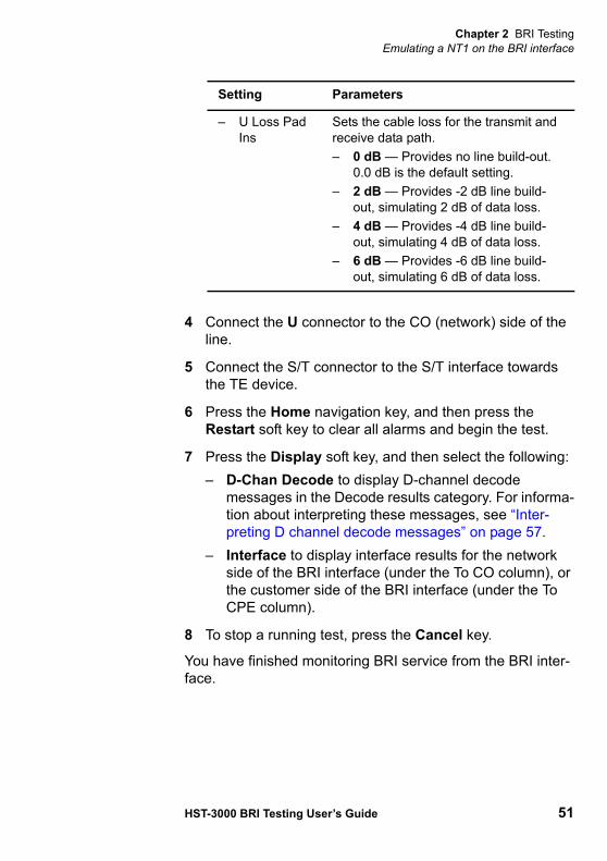
4 Connect the U connector to the CO (network) side of the line.
5 Connect the S/T connector to the S/T interface towards the TE device.
6 Press the Home navigation key, and then press the Restart soft key to clear all alarms and begin the test.
7 Press the Display soft key, and then select the following:– D-Chan Decode to display D-channel decode
messages in the Decode results category. For informa-tion about interpreting these messages, see “Inter-preting D channel decode messages” on page 57.
– Interface to display interface results for the network side of the BRI interface (under the To CO column), or the customer side of the BRI interface (under the To CPE column).
8 To stop a running test, press the Cancel key.
You have finished monitoring BRI service from the BRI inter-face.
– U Loss Pad Ins
Sets the cable loss for the transmit and receive data path.– 0 dB — Provides no line build-out.
0.0 dB is the default setting.– 2 dB — Provides -2 dB line build-
out, simulating 2 dB of data loss.– 4 dB — Provides -4 dB line build-
out, simulating 4 dB of data loss.– 6 dB — Provides -6 dB line build-
out, simulating 6 dB of data loss.
Setting Parameters

Chapter 2 BRI TestingTesting the physical layer
52 HST-3000 BRI Testing User’s Guide
Testing the physical layerYou can use the HST-3000 to perform bit error rate tests (BERT or BER testing) and insert CRC and FEBE errors to check the functioning of the physical line on the U interface.
To test the physical layer on the U interface
1 If the HST is off, press the green power button to power on the unit.The BRI Measurements menu may take several seconds to appear.
2 Select BERT (IDSL).The HST-3000 launches the test application.
3 Press the Configure navigation key.
4 Press the BRI soft key.
Chapter 2 BRI TestingTesting the physical layer
HST-3000 BRI Testing User’s Guide 53
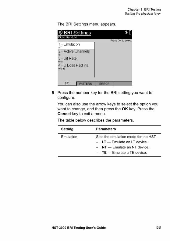
The BRI Settings menu appears.
5 Press the number key for the BRI setting you want to configure. You can also use the arrow keys to select the option you want to change, and then press the OK key. Press the Cancel key to exit a menu. The table below describes the parameters.
Setting Parameters
Emulation Sets the emulation mode for the HST. – LT — Emulate an LT device.– NT — Emulate an NT device.– TE — Emulate a TE device.

Chapter 2 BRI TestingTesting the physical layer
54 HST-3000 BRI Testing User’s Guide
6 Press the PATTERN soft key.
Active Channels The BRI channels you want to test:– B1. Starts a BER test, sending the
pattern on the B1 channel.– B2. Starts a BER test, sending the
pattern on the B2 channel.– B1,B2. Starts a dual BER test,
sending identical patterns on the B1 and B2 channels.
– 2B. Starts a 128K BER test, send-ing one pattern over both bearer channels.
– 2B+D. Starts a BER test, sending one pattern over both bearer chan-nels and the D channel (available in LT mode only).
Bit Rate Bit rate over the tested channel: 56K or 64K.
Loop Address Address on the NT device used for looping. (Available in LT mode only.)
EOC Message Code supplied by the LT for looping an NT device. Table 26 on page 103 lists the available codes. (Available in LT mode only.)
U Loss Pad Ins Enables emulation of various cable losses. The selected cable loss affects the transmit and receive data path.– 0 dB — Provides no line build-out.– 2 dB — Provides -2 dB line build-
out, simulating 2 dB of data loss.– 4 dB — Provides -4 dB line build-
out, simulating 4 dB of data loss.– 6 dB — Provides -6 dB line build-
out, simulating 6 dB of data loss.
Setting Parameters

Chapter 2 BRI TestingTesting the physical layer
HST-3000 BRI Testing User’s Guide 55
7 Select and then define each of the following settings:
8 Press the ERROR soft key.Select and then define each of the following settings:
9 Optional. If you want to run a timed test, press the Event soft key to display the Event Settings menu, and then do the following:
a Select Timed Test, and then select Enable.
Setting Parameters
Pattern Test pattern to inject. Table 22 on page 100 lists available test patterns.
User Bit Patt User-defined bit pattern, 3-32 characters of zeros and ones. (Available only if Pattern is set to User Bit Pattern.)
Setting Parameters
Errors Type of error to inject.– Bit Error– CRC Error– FEBE Error
Rate Type Method by which bit errors are inserted. (Available only if Errors is Bit Error.)– Single– Rate – Multiple
Count Number of errors to insert. (Available only if Rate Type is Multiple.)
Rate Insertion rate of errors. (Available only if Rate Type is set to Rate.)

Chapter 2 BRI TestingTesting the physical layer
56 HST-3000 BRI Testing User’s Guide
The Timed Test Dur setting appears and the timed test icon appears in the upper right corner of the display screen.
b To specify how long the test should run, select Timed Test Dur, and then enter the test duration in hours, minutes, and seconds.
10 Connect the U connector on the HST-3000 to the CO (network) side of the line.
11 Verify that the Sync LED is illuminated to ensure that the HST is synchronized with a valid signal.
12 Verify that the Data LED is illuminated to ensure that the HST has obtained pattern synchronization.
13 Press the Home navigation key to display results.
14 To insert errors into the line, press the Action soft key, and then select one of the following:– Enable Bit Error—Inserts a single bit error. This
action appears if you selected Single as the rate type in step 8.
– Enable # Bit Errors—Where # represents the number of bit errors that will be inserted. This action appears if you selected Multiple as the Rate type in step 8.
– Enable Bit Error Rate—Where Rate represents the actual rate you specified. This action appears if you selected Rate as the Rate type in step 8.
– Enable FEBE Error—Inserts a continuous stream of FEBE errors. This action appears if you selected FEBE Error as the error type in step 8.
– Enable CRC Error—Inserts a continuous stream of CRC errors. This action appears if you selected CRC Error as the error type in step 8.
The error or errors are inserted into the line.
15 Optional. To loop the HST-3000 while in NT mode, press the Action soft key, and then do the following:
Chapter 2 BRI TestingInterpreting D channel decode messages
HST-3000 BRI Testing User’s Guide 57
a Select Loop Action, and then press the right arrow key to display a list of channels.
b Use the up and down arrow keys to choose the channel to loop, and then select OK.
BER testing is complete.
Interpreting D channel decode messagesWhen you monitor or terminate ISDN BRI service, you can isolate and locate problems by viewing D channel decode messages for all captured transmitted and received frames.
The decode messages fall into two categories:
– Messages concerning the establishment and mainte-nance of the D channel link (layer 2 messages). These are often referred to as LAPD (Link Access Procedure D-Channel) messages.
– Messages concerning the ISDN calls, such as the reason a call is rejected, who is disconnecting a call, and the call’s bearer capability (layer 3 messages). These are often referred to as Q.931 messages.
Chapter 2 BRI TestingInterpreting D channel decode messages
58 HST-3000 BRI Testing User’s Guide
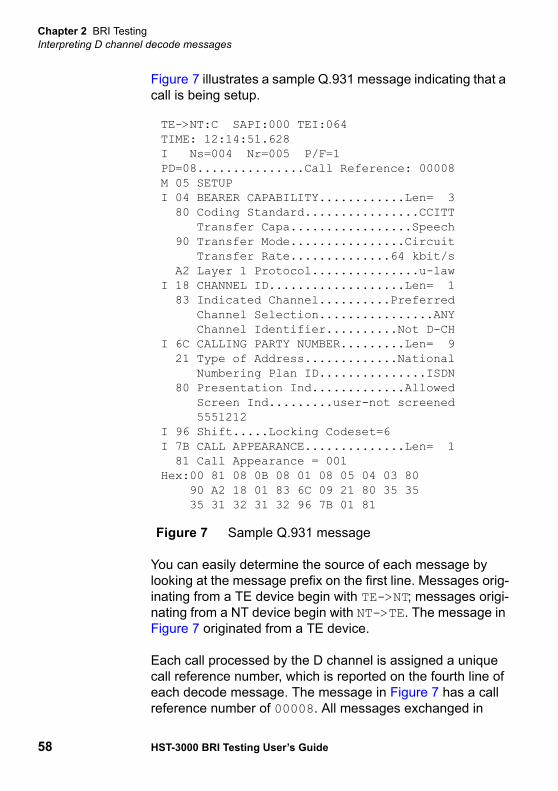
Figure 7 illustrates a sample Q.931 message indicating that a call is being setup.
You can easily determine the source of each message by looking at the message prefix on the first line. Messages orig-inating from a TE device begin with TE->NT; messages origi-nating from a NT device begin with NT->TE. The message in Figure 7 originated from a TE device.
Each call processed by the D channel is assigned a unique call reference number, which is reported on the fourth line of each decode message. The message in Figure 7 has a call reference number of 00008. All messages exchanged in
TE->NT:C SAPI:000 TEI:064TIME: 12:14:51.628I Ns=004 Nr=005 P/F=1 PD=08...............Call Reference: 00008M 05 SETUPI 04 BEARER CAPABILITY............Len= 3 80 Coding Standard................CCITT Transfer Capa.................Speech 90 Transfer Mode................Circuit Transfer Rate..............64 kbit/s A2 Layer 1 Protocol...............u-lawI 18 CHANNEL ID...................Len= 1 83 Indicated Channel..........Preferred Channel Selection................ANY Channel Identifier..........Not D-CHI 6C CALLING PARTY NUMBER.........Len= 9 21 Type of Address.............National Numbering Plan ID...............ISDN 80 Presentation Ind.............Allowed Screen Ind.........user-not screened 5551212I 96 Shift.....Locking Codeset=6I 7B CALL APPEARANCE..............Len= 1 81 Call Appearance = 001Hex:00 81 08 0B 08 01 08 05 04 03 80 90 A2 18 01 83 6C 09 21 80 35 35 35 31 32 31 32 96 7B 01 81
Figure 7 Sample Q.931 message
Chapter 2 BRI TestingInterpreting D channel decode messages
HST-3000 BRI Testing User’s Guide 59
reference to the call have the same call reference number. When viewing decode messages on a D channel processing a number of calls, it is important to verify the call reference number for each message because messages for each call are not presented as a group. A message indicating one call has been connected may be followed immediately by a message indicating a different call has been disconnected.
For details on viewing and navigating through D channel decode messages, see “Viewing and navigating decode messages” on page 60.
For descriptions of each individual decode message, see “D-Chan decode results” on page 86.
LAPDmessages
LAPD messages are useful when verifying the status of the D channel link. Complaints prompting you to look at LAPD messages include:
– The D channel does not go in service.– D channel communications are lost for no known reason.– Callers are experiencing excessive delays or timeouts
when trying to place calls.
Using the LAPD messages, you can determine why a D channel link is not established, if a link is being terminated, and why a link is being terminated. Three types of frames are transmitted in LAPD: Information frames, which carry detailed call information, Unnumbered frames, which are used to establish or terminate D channel communications, and Super-visory frames, which are used to maintain link communica-tions after a link has been established.
For detailed descriptions of unnumbered frame messages, see “LAPD Unnumbered frame messages” on page 86. For detailed descriptions of supervisory frame messages, see “LAPD Supervisory frame messages” on page 88.

Chapter 2 BRI TestingInterpreting D channel decode messages
60 HST-3000 BRI Testing User’s Guide
Q.931messages
Q.931 messages are useful for observing the call setup process, and identifying key information about each call, such as the called party number, transfer capability (which indicates whether the call is a voice or data call), and the channel selec-tion (the B channel carrying the call).
Each Q.931 message begins with a message prefix on the first line which indicates where the message originated. Messages originating from a TE device begin with TE->NT; messages originating from a NT device begin with NT->TE. The call reference number for the message appears on the fourth line. The fifth line indicates the type of message being sent (for example, SETUP or CONNECT).
Finally, information elements pertaining to the call are listed. For SETUP messages, the elements roughly correspond to the settings required to place a call from the HST, such as the ISDN and Call settings listed in “Placing circuit calls” on page 16. Additional call settings are also listed in the SETUP messages.
For DISCONNECT messages, the cause or reason for the call being disconnected is reported. For example, if the call is disconnected simply because one of the users hangs up the phone, the cause is reported as a Normal Clearing.
If a call cannot be connected, and as a result a RELEASE message is issued in response to a SETUP request, the RELEASE message reports the cause for the disconnection.
For detailed descriptions of Q.931 messages, see “Q.931 messages” on page 89.
Viewing andnavigating
decodemessages
The D-Chan Decode Results screen displays decode text messages in the order they are received on the HST.
To navigate through the messages– Use the up and down arrows to scroll through the text of a
message.
Chapter 2 BRI TestingInterpreting D channel decode messages
HST-3000 BRI Testing User’s Guide 61
– Use Previous (<) to view the previous message in the message buffer.
– Use Next (>) to view the next message in the message buffer.
– Use Home (2nd fnc + <) to view the first message in the message buffer.
– Use End (2nd fnc + >) to view the last message in the message buffer.
Clearing themessage buffer
The HST decode message buffer can store up to 32,000 bytes of decode text data. When you monitor or terminate ISDN BRI service, the HST captures D Channel frames and displays the associated decode text messages until the buffer becomes full. When the buffer is full, the HST stops capturing frames. You can clear the message buffer, enabling the HST to continue capturing frames.
To clear the HST message buffer– On any results screen (for example, the D-Chan Decode
Results screen), press the Action soft key, and then select Clear D-Chan Decodes.
The message buffer is cleared.
NOTE:You can easily determine how many messages have been captured by looking at the Message count (for example, Message 2 of 125), located to the right above the decode text on the D-Chan Decode Results screen.
NOTE:You can easily determine how full the buffer is by looking at the % Full indicator, located to the left above the decode text on the D-Chan Decode result category screen.

Chapter 2 BRI TestingRestarting tests
62 HST-3000 BRI Testing User’s Guide
Capturingdecode text inan ASCII text
file
You can capture all of the decode text stored in the message buffer and store it in an ASCII text file. You can then view the text file at a later time. For details on viewing text files on the HST, refer to the HST-3000 Base Unit User’s Guide.
To capture decode text
1 Press the Results soft key.
2 Select Capture D-chan decodes.A dialog box appears prompting you to enter the file name for the .txt file.
3 Enter the name of the file.
4 Press the Ok key.
The decode text is captured in the ASCII text file.
Restarting testsWhen you use the HST-3000 to place and receive ISDN BRI calls, pressing the Restart soft key clears statistical and historical results and restarts your test.
Pressing Restart does not:
– Disrupt current calls.– Clear D-channel decode text. A separate Clear Buffer
action is available for clearing the decode message buffer (see “Clearing the message buffer” on page 61).
NOTE:You can use the Clear History action to clear history results while continuing to accumulate statistical results (see “Clearing history results” on page 63).
Chapter 2 BRI TestingViewing test results
HST-3000 BRI Testing User’s Guide 63
Viewing test resultsThe following procedure describes how to view test results.
To view test results
1 Configure and run a test.
2 Press the Home navigation key.
3 Press the Display soft key.The test categories appear.
4 Select a category.The test results for the selected category appear. For descriptions of test results, see “Test Results” on page 69.
Clearing history resultsThe following procedure describes how to clear history results in the LED and Summary categories.
To clear history results
1 Configure and run a test.
2 Press the Home navigation key.
3 Press the Results soft key.
4 Select Clear History.
The HST-3000 clears any history results in the LED and Summary categories. Statistical results are not cleared and continue to accumulate.

Chapter 2 BRI TestingClearing history results
64 HST-3000 BRI Testing User’s Guide
3
HST-3000 BRI Testing User’s Guide 65
Chapter 3Troubleshooting
This chapter describes how to identify and correct problems related to the BRI testing with the HST-3000. Topics discussed in this chapter include the following:
– “Resolving problems” on page 66
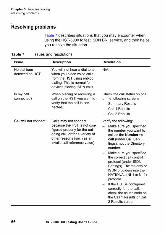
Chapter 3 TroubleshootingResolving problems
66 HST-3000 BRI Testing User’s Guide
Resolving problemsTable 7 describes situations that you may encounter when using the HST-3000 to test ISDN BRI service, and then helps you resolve the situation.
Table 7 Issues and resolutions
Issue Description Resolution
No dial tone detected on HST
You will not hear a dial tone when you place voice calls from the HST using enbloc dialing. This is normal for devices placing ISDN calls.
N/A.
Is my call connected?
When placing or receiving a call on the HST, you want to verify that the call is con-nected.
Check the call status on one of the following screens:– Summary Results– Call 1 Results– Call 2 Results
Call will not connect Calls may not connect because the HST is not con-figured properly for the out-going call, or for a variety of other reasons (such as an invalid call reference value).
Verify the following:– Make sure you specified
the number you want to call as the Number to call (under Call Set-tings); not the Directory number.
– Make sure you specified the correct call control protocol (under ISDN Settings). The majority of ISDN providers use the NATIONAL (NI-1 or NI-2) protocol.
– If the HST is configured correctly for the call, check the cause code on the Call 1 Results or Call 2 Results screen.
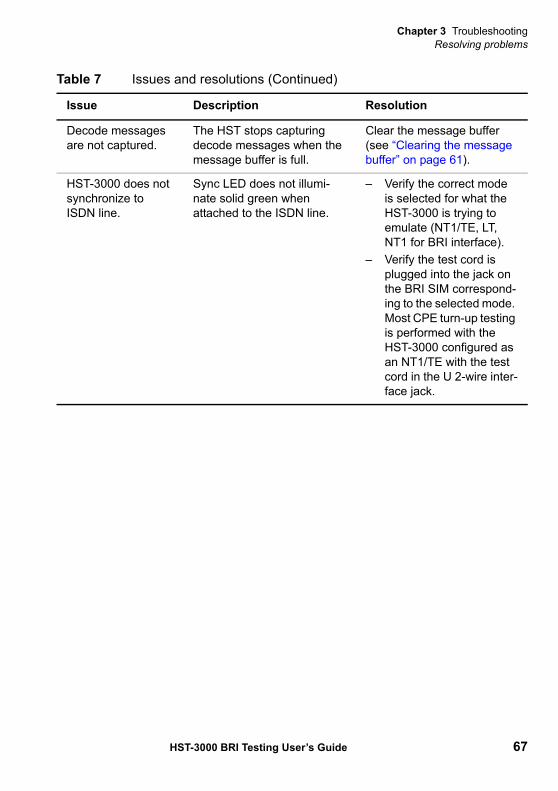
Chapter 3 TroubleshootingResolving problems
HST-3000 BRI Testing User’s Guide 67
Decode messages are not captured.
The HST stops capturing decode messages when the message buffer is full.
Clear the message buffer (see “Clearing the message buffer” on page 61).
HST-3000 does not synchronize to ISDN line.
Sync LED does not illumi-nate solid green when attached to the ISDN line.
– Verify the correct mode is selected for what the HST-3000 is trying to emulate (NT1/TE, LT, NT1 for BRI interface).
– Verify the test cord is plugged into the jack on the BRI SIM correspond-ing to the selected mode. Most CPE turn-up testing is performed with the HST-3000 configured as an NT1/TE with the test cord in the U 2-wire inter-face jack.
Table 7 Issues and resolutions (Continued)
Issue Description Resolution
Chapter 3 TroubleshootingResolving problems
68 HST-3000 BRI Testing User’s Guide

A
HST-3000 BRI Testing User’s Guide 69
Appendix ATest Results
This appendix describes the test result categories and the results within each category that are available when performing ISDN BRI tests. Topics discussed in this appendix include the following:
– “About test results” on page 70– “Summary results” on page 70– “Interface results” on page 73– “BERT results” on page 77– “LED results” on page 78– “ISDN results” on page 80– “Call 1/Call 2” on page 83– “D-Chan Decode” on page 85– “Time results” on page 85– “D-Chan decode results” on page 86– “Q.931 Cause Values” on page 90– “Saving and printing results” on page 97
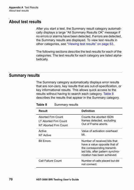
Appendix A Test ResultsAbout test results
70 HST-3000 BRI Testing User’s Guide
About test resultsAfter you start a test, the Summary result category automati-cally displays a large “All Summary Results OK” message if no errors or alarms have been detected. If errors are detected, the Summary results are displayed. To view test results in other categories, see “Viewing test results” on page 63.
The following sections describe the test results for each of the categories. The test results for each category are listed alpha-betically.
Summary resultsThe Summary category automatically displays error results that are non-zero, key results that are out-of-specification, or key informational results. This allows quick access to the results without having to search each category. Table 8 describes the results that appear in the Summary category.
Table 8 Summary results
Result Definition
Aborted Frm CountLT Aborted Frm CountNT Aborted Frm Count
Counts the aborted ISDN frames detected, excluding Out of Frame aborts.
ActiveNT Active
Value of activation overhead bit.
Bit Errors Number of received bits that have a value opposite that of the corresponding transmit-ted bits, after pattern synchro-nization has been achieved.
Call Failure Count Number of calls placed but did not connect.
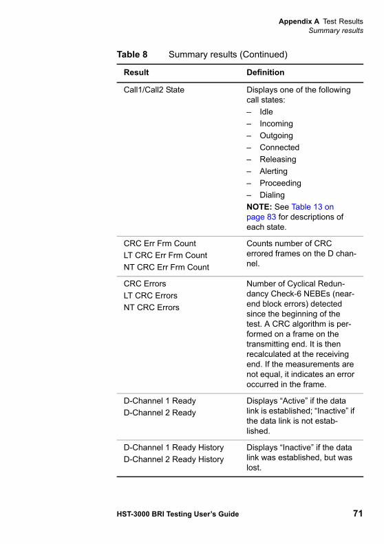
Appendix A Test ResultsSummary results
HST-3000 BRI Testing User’s Guide 71
Call1/Call2 State Displays one of the following call states:– Idle– Incoming– Outgoing– Connected– Releasing– Alerting– Proceeding– DialingNOTE: See Table 13 on page 83 for descriptions of each state.
CRC Err Frm CountLT CRC Err Frm CountNT CRC Err Frm Count
Counts number of CRC errored frames on the D chan-nel.
CRC ErrorsLT CRC ErrorsNT CRC Errors
Number of Cyclical Redun-dancy Check-6 NEBEs (near-end block errors) detected since the beginning of the test. A CRC algorithm is per-formed on a frame on the transmitting end. It is then recalculated at the receiving end. If the measurements are not equal, it indicates an error occurred in the frame.
D-Channel 1 ReadyD-Channel 2 Ready
Displays “Active” if the data link is established; “Inactive” if the data link is not estab-lished.
D-Channel 1 Ready HistoryD-Channel 2 Ready History
Displays “Inactive” if the data link was established, but was lost.
Table 8 Summary results (Continued)
Result Definition
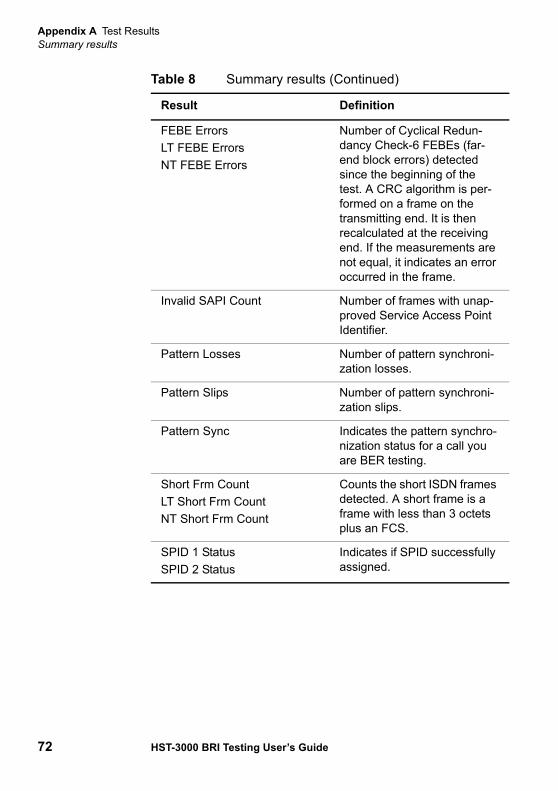
Appendix A Test ResultsSummary results
72 HST-3000 BRI Testing User’s Guide
FEBE ErrorsLT FEBE ErrorsNT FEBE Errors
Number of Cyclical Redun-dancy Check-6 FEBEs (far-end block errors) detected since the beginning of the test. A CRC algorithm is per-formed on a frame on the transmitting end. It is then recalculated at the receiving end. If the measurements are not equal, it indicates an error occurred in the frame.
Invalid SAPI Count Number of frames with unap-proved Service Access Point Identifier.
Pattern Losses Number of pattern synchroni-zation losses.
Pattern Slips Number of pattern synchroni-zation slips.
Pattern Sync Indicates the pattern synchro-nization status for a call you are BER testing.
Short Frm CountLT Short Frm CountNT Short Frm Count
Counts the short ISDN frames detected. A short frame is a frame with less than 3 octets plus an FCS.
SPID 1 StatusSPID 2 Status
Indicates if SPID successfully assigned.
Table 8 Summary results (Continued)
Result Definition
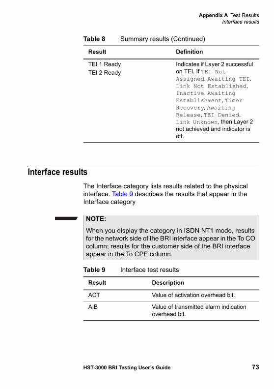
Appendix A Test ResultsInterface results
HST-3000 BRI Testing User’s Guide 73
Interface resultsThe Interface category lists results related to the physical interface. Table 9 describes the results that appear in the Interface category
TEI 1 ReadyTEI 2 Ready
Indicates if Layer 2 successful on TEl. If TEI Not Assigned, Awaiting TEI, Link Not Established, Inactive, Awaiting Establishment, Timer Recovery, Awaiting Release, TEI Denied, Link Unknown, then Layer 2 not achieved and indicator is off.
Table 8 Summary results (Continued)
Result Definition
NOTE:
When you display the category in ISDN NT1 mode, results for the network side of the BRI interface appear in the To CO column; results for the customer side of the BRI interface appear in the To CPE column.
Table 9 Interface test results
Result Description
ACT Value of activation overhead bit.
AIB Value of transmitted alarm indication overhead bit.
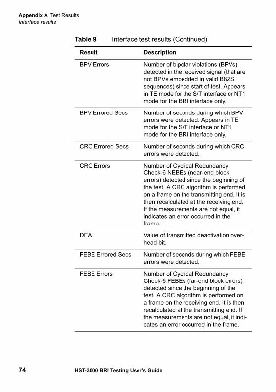
Appendix A Test ResultsInterface results
74 HST-3000 BRI Testing User’s Guide
BPV Errors Number of bipolar violations (BPVs) detected in the received signal (that are not BPVs embedded in valid B8ZS sequences) since start of test. Appears in TE mode for the S/T interface or NT1 mode for the BRI interface only.
BPV Errored Secs Number of seconds during which BPV errors were detected. Appears in TE mode for the S/T interface or NT1 mode for the BRI interface only.
CRC Errored Secs Number of seconds during which CRC errors were detected.
CRC Errors Number of Cyclical Redundancy Check-6 NEBEs (near-end block errors) detected since the beginning of the test. A CRC algorithm is performed on a frame on the transmitting end. It is then recalculated at the receiving end. If the measurements are not equal, it indicates an error occurred in the frame.
DEA Value of transmitted deactivation over-head bit.
FEBE Errored Secs Number of seconds during which FEBE errors were detected.
FEBE Errors Number of Cyclical Redundancy Check-6 FEBEs (far-end block errors) detected since the beginning of the test. A CRC algorithm is performed on a frame on the receiving end. It is then recalculated at the transmitting end. If the measurements are not equal, it indi-cates an error occurred in the frame.
Table 9 Interface test results (Continued)
Result Description

Appendix A Test ResultsInterface results
HST-3000 BRI Testing User’s Guide 75
Frame Errors Number of frame errors received since start of test. Appears in TE mode for the S/T interface or NT1 mode for the BRI interface only.
Frame Errored Secs Number of seconds during which frame errors were detected. Appears in TE mode for the S/T interface or NT1 mode for the BRI interface only.
Invalid SAPI Count Number of frames received with an invalid SAPI (service access point iden-tifier). Appears in TE mode for the S/T interface or NT1 mode for the BRI inter-face only.
Layer1 State Displays the current interface activation state. Its major activation states are awaiting signal, synchronized, and alerting. For the LT result, displays cur-rent J state for the LT side of line. For the NT result, displays current H state for the NT side of line.
Loop State Displays current loop state and channel looped. Valid results include the follow-ing: No Loop, Loop B1, Loop B2, Loop B1+B2, 2B+D. Appears in NT1/TE mode only.
PS1 – Normal indicates that at least 28 volts is present on the line.
– Reversed indicates reversed polarity of the voltage.
– Not present indicates that less than 28 volts is present on the line.
Appears in TE mode for the S/T inter-face or NT1 mode for the BRI interface only.
Table 9 Interface test results (Continued)
Result Description
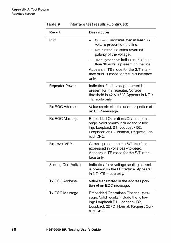
Appendix A Test ResultsInterface results
76 HST-3000 BRI Testing User’s Guide
PS2 – Normal indicates that at least 36 volts is present on the line.
– Reversed indicates reversed polarity of the voltage.
– Not present indicates that less than 36 volts is present on the line.
Appears in TE mode for the S/T inter-face or NT1 mode for the BRI interface only.
Repeater Power Indicates if high-voltage current is present for the repeater. Voltage threshold is 42 V ±3 V. Appears in NT1/TE mode only.
Rx EOC Address Value received in the address portion of an EOC message.
Rx EOC Message Embedded Operations Channel mes-sage. Valid results include the follow-ing: Loopback B1, Loopback B2, Loopback 2B+D, Normal, Request Cor-rupt CRC.
Rx Level VPP Current present on the S/T interface, expressed in volts peak-to-peak. Appears in TE mode for the S/T inter-face only.
Sealing Curr Active Indicates if low-voltage sealing current is present on the U interface. Appears in NT1/TE mode only.
Tx EOC Address Value transmitted in the address por-tion of an EOC message.
Tx EOC Message Embedded Operations Channel mes-sage. Valid results include the follow-ing: Loopback B1, Loopback B2, Loopback 2B+D, Normal, Request Cor-rupt CRC.
Table 9 Interface test results (Continued)
Result Description
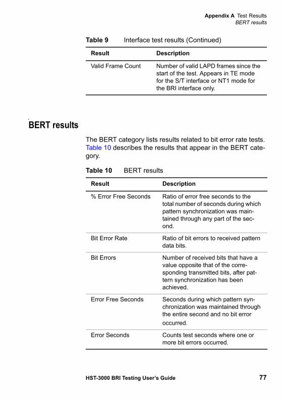
Appendix A Test ResultsBERT results
HST-3000 BRI Testing User’s Guide 77
BERT resultsThe BERT category lists results related to bit error rate tests. Table 10 describes the results that appear in the BERT cate-gory.
Valid Frame Count Number of valid LAPD frames since the start of the test. Appears in TE mode for the S/T interface or NT1 mode for the BRI interface only.
Table 9 Interface test results (Continued)
Result Description
Table 10 BERT results
Result Description
% Error Free Seconds Ratio of error free seconds to the total number of seconds during which pattern synchronization was main-tained through any part of the sec-ond.
Bit Error Rate Ratio of bit errors to received pattern data bits.
Bit Errors Number of received bits that have a value opposite that of the corre-sponding transmitted bits, after pat-tern synchronization has been achieved.
Error Free Seconds Seconds during which pattern syn-chronization was maintained through the entire second and no bit erroroccurred.
Error Seconds Counts test seconds where one or more bit errors occurred.
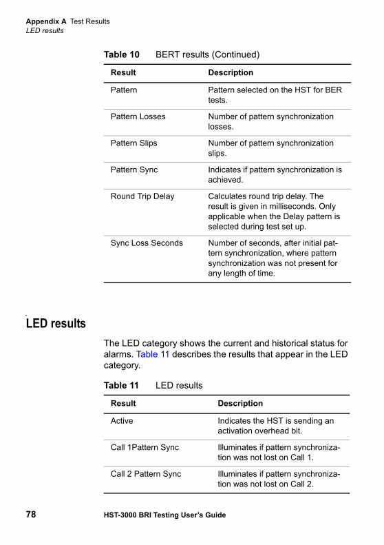
Appendix A Test ResultsLED results
78 HST-3000 BRI Testing User’s Guide
LED resultsThe LED category shows the current and historical status for alarms. Table 11 describes the results that appear in the LED category.
Pattern Pattern selected on the HST for BER tests.
Pattern Losses Number of pattern synchronization losses.
Pattern Slips Number of pattern synchronization slips.
Pattern Sync Indicates if pattern synchronization is achieved.
Round Trip Delay Calculates round trip delay. The result is given in milliseconds. Only applicable when the Delay pattern is selected during test set up.
Sync Loss Seconds Number of seconds, after initial pat-tern synchronization, where pattern synchronization was not present for any length of time.
Table 10 BERT results (Continued)
Result Description
Table 11 LED results
Result Description
Active Indicates the HST is sending an activation overhead bit.
Call 1Pattern Sync Illuminates if pattern synchroniza-tion was not lost on Call 1.
Call 2 Pattern Sync Illuminates if pattern synchroniza-tion was not lost on Call 2.

Appendix A Test ResultsLED results
HST-3000 BRI Testing User’s Guide 79
Call 1Pattern Sync His-tory
Illuminates if pattern synchroniza-tion was previously detected on Call 1.
Call 2 Pattern Sync His-tory
Illuminates if pattern synchroniza-tion was previously detected on Call 2.
TEI 1 ReadyTEI 2 Ready
Indicates if Layer 2 successful on TEl. If TEI Not Assigned, Awaiting TEI, Link Not Established, Await-ing Establishment, Timer Recov-ery, Awaiting Release, TEI Denied, Link Unknown, then Layer 2 not achieved and indicator is off.
TEI 1 Ready HistoryTEI 2 Ready History
Indicates if TEI achieved but later lost Layer 2.
Pattern Sync Pattern synchronization achieved.
Pattern Sync History Indicates if pattern synchroniza-tion was achieved and then sub-sequently lost.
Repeater Power Indicates if high-voltage current is present for the repeater. Voltage threshold is 42 V ±3 V.
Sealing Curr Active Indicates if active sealing current is present on the U interface.
Sync’d Frame synchronization detected.
Table 11 LED results (Continued)
Result Description

Appendix A Test ResultsISDN results
80 HST-3000 BRI Testing User’s Guide
ISDN resultsThe ISDN category shows results pertaining to the throughput of frames and their utilization. Results in this category accu-mulate after test restart. Table 12 describes the results that appear in the ISDN category.
Table 12 ISDN test results
Result Description
Aborted Frm Count Counts the aborted ISDN frames detected, excluding Out of Frame aborts.
Average % Utilization The average percent of link utiliza-tion on the D channel since the start of the test. Calculated as (total octets in frames ÷ total octets received).
Call Clearing Count Number of calls placed and subse-quently disconnected.
Call Connect Count Number of calls placed and subse-quently connected.
Call Failure Count Number of calls placed but did not connect.
Call Placement Count Number of calls placed.
CRC Err Frm Count Counts number of CRC errors within a frame on the D channel.
Erred Frame Count Number of valid frames with one or more of the following error condi-tions: undefined control field "S" or "U" frames with incorrect length, or "I" frame with a long information field.
Frame Reject Frames Number of frame-reject (FRMR) frames used to indicate that an improper frame has arrived.
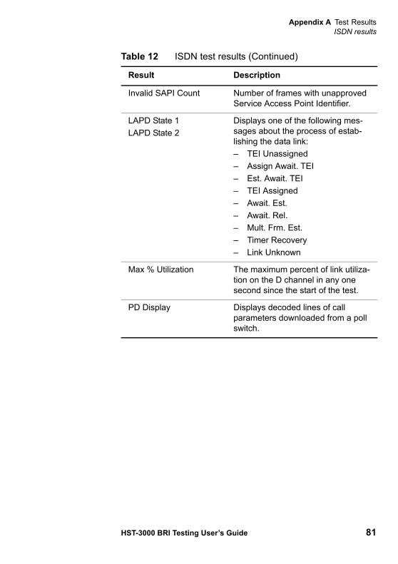
Appendix A Test ResultsISDN results
HST-3000 BRI Testing User’s Guide 81
Invalid SAPI Count Number of frames with unapproved Service Access Point Identifier.
LAPD State 1LAPD State 2
Displays one of the following mes-sages about the process of estab-lishing the data link:– TEI Unassigned– Assign Await. TEI– Est. Await. TEI– TEI Assigned– Await. Est.– Await. Rel.– Mult. Frm. Est.– Timer Recovery– Link Unknown
Max % Utilization The maximum percent of link utiliza-tion on the D channel in any one second since the start of the test.
PD Display Displays decoded lines of call parameters downloaded from a poll switch.
Table 12 ISDN test results (Continued)
Result Description
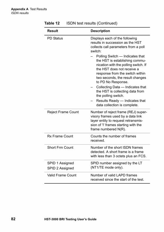
Appendix A Test ResultsISDN results
82 HST-3000 BRI Testing User’s Guide
PD Status Displays each of the following results in succession as the HST collects call parameters from a poll switch:– Polling Switch — Indicates that
the HST is establishing commu-nication with the polling switch. If the HST does not receive a response from the switch within two seconds, the result changes to PD No Response.
– Collecting Data — Indicates that the HST is collecting data from the polling switch.
– Results Ready — Indicates that data collection is complete.
Reject Frame Count Number of reject frame (REJ) super-visory frames used by a data link layer entity to request retransmis-sion of 'I' frames starting with the frame numbered N(R).
Rx Frame Count Counts the number of frames received.
Short Frm Count Number of the short ISDN frames detected. A short frame is a frame with less than 3 octets plus an FCS.
SPID 1 AssignedSPID 2 Assigned
SPID number assigned by the LT (NT1/TE mode only).
Valid Frame Count Number of valid LAPD frames received since the start of the test.
Table 12 ISDN test results (Continued)
Result Description
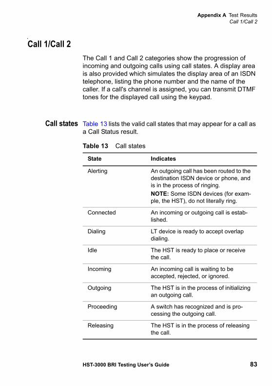
Appendix A Test ResultsCall 1/Call 2
HST-3000 BRI Testing User’s Guide 83
Call 1/Call 2The Call 1 and Call 2 categories show the progression of incoming and outgoing calls using call states. A display area is also provided which simulates the display area of an ISDN telephone, listing the phone number and the name of the caller. If a call's channel is assigned, you can transmit DTMF tones for the displayed call using the keypad.
Call states Table 13 lists the valid call states that may appear for a call as a Call Status result.
Table 13 Call states
State Indicates
Alerting An outgoing call has been routed to the destination ISDN device or phone, and is in the process of ringing.NOTE: Some ISDN devices (for exam-ple, the HST), do not literally ring.
Connected An incoming or outgoing call is estab-lished.
Dialing LT device is ready to accept overlap dialing.
Idle The HST is ready to place or receive the call.
Incoming An incoming call is waiting to be accepted, rejected, or ignored.
Outgoing The HST is in the process of initializing an outgoing call.
Proceeding A switch has recognized and is pro-cessing the outgoing call.
Releasing The HST is in the process of releasing the call.
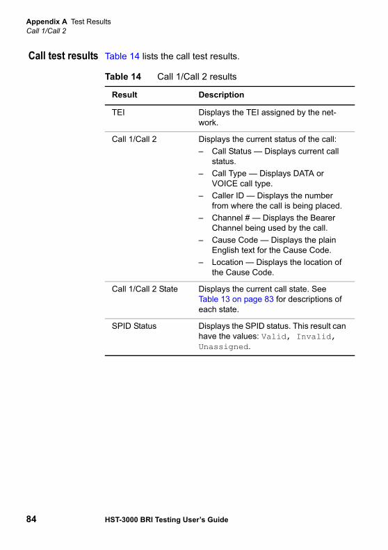
Appendix A Test ResultsCall 1/Call 2
84 HST-3000 BRI Testing User’s Guide
Call test results Table 14 lists the call test results.
Table 14 Call 1/Call 2 results
Result Description
TEI Displays the TEI assigned by the net-work.
Call 1/Call 2 Displays the current status of the call:– Call Status — Displays current call
status.– Call Type — Displays DATA or
VOICE call type.– Caller ID — Displays the number
from where the call is being placed.– Channel # — Displays the Bearer
Channel being used by the call.– Cause Code — Displays the plain
English text for the Cause Code.– Location — Displays the location of
the Cause Code.
Call 1/Call 2 State Displays the current call state. See Table 13 on page 83 for descriptions of each state.
SPID Status Displays the SPID status. This result can have the values: Valid, Invalid, Unassigned.
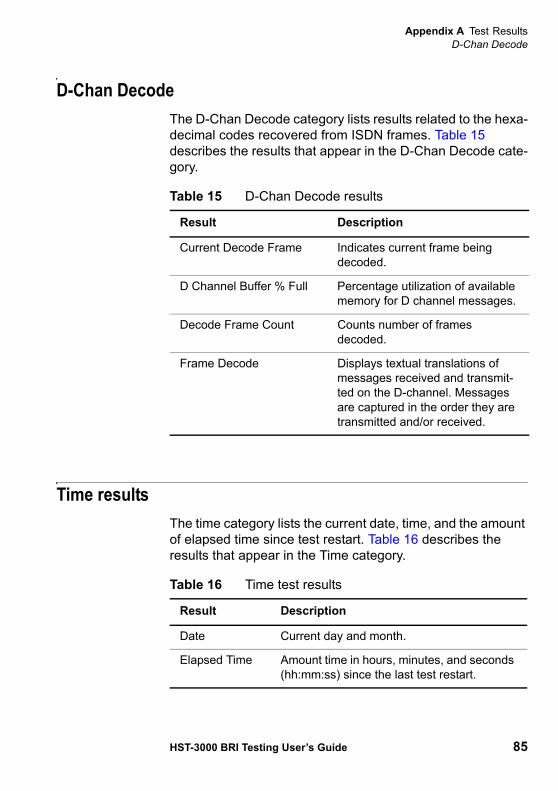
Appendix A Test ResultsD-Chan Decode
HST-3000 BRI Testing User’s Guide 85
D-Chan DecodeThe D-Chan Decode category lists results related to the hexa-decimal codes recovered from ISDN frames. Table 15 describes the results that appear in the D-Chan Decode cate-gory.
Time resultsThe time category lists the current date, time, and the amount of elapsed time since test restart. Table 16 describes the results that appear in the Time category.
Table 15 D-Chan Decode results
Result Description
Current Decode Frame Indicates current frame being decoded.
D Channel Buffer % Full Percentage utilization of available memory for D channel messages.
Decode Frame Count Counts number of frames decoded.
Frame Decode Displays textual translations of messages received and transmit-ted on the D-channel. Messages are captured in the order they are transmitted and/or received.
Table 16 Time test results
Result Description
Date Current day and month.
Elapsed Time Amount time in hours, minutes, and seconds (hh:mm:ss) since the last test restart.
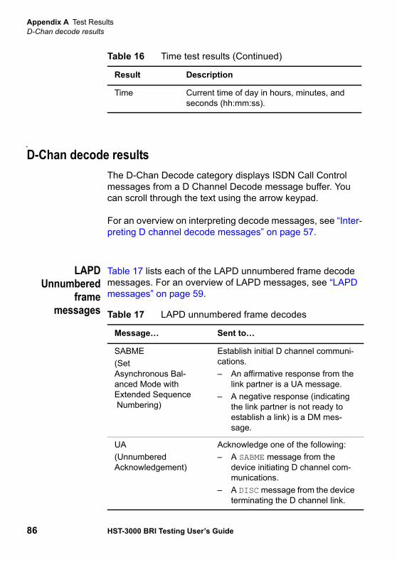
Appendix A Test ResultsD-Chan decode results
86 HST-3000 BRI Testing User’s Guide
D-Chan decode resultsThe D-Chan Decode category displays ISDN Call Control messages from a D Channel Decode message buffer. You can scroll through the text using the arrow keypad.
For an overview on interpreting decode messages, see “Inter-preting D channel decode messages” on page 57.
LAPDUnnumbered
framemessages
Table 17 lists each of the LAPD unnumbered frame decode messages. For an overview of LAPD messages, see “LAPD messages” on page 59.
Time Current time of day in hours, minutes, and seconds (hh:mm:ss).
Table 16 Time test results (Continued)
Result Description
Table 17 LAPD unnumbered frame decodes
Message… Sent to…
SABME(Set Asynchronous Bal-anced Mode with Extended Sequence Numbering)
Establish initial D channel communi-cations. – An affirmative response from the
link partner is a UA message.– A negative response (indicating
the link partner is not ready to establish a link) is a DM mes-sage.
UA(Unnumbered Acknowledgement)
Acknowledge one of the following:– A SABME message from the
device initiating D channel com-munications.
– A DISC message from the device terminating the D channel link.
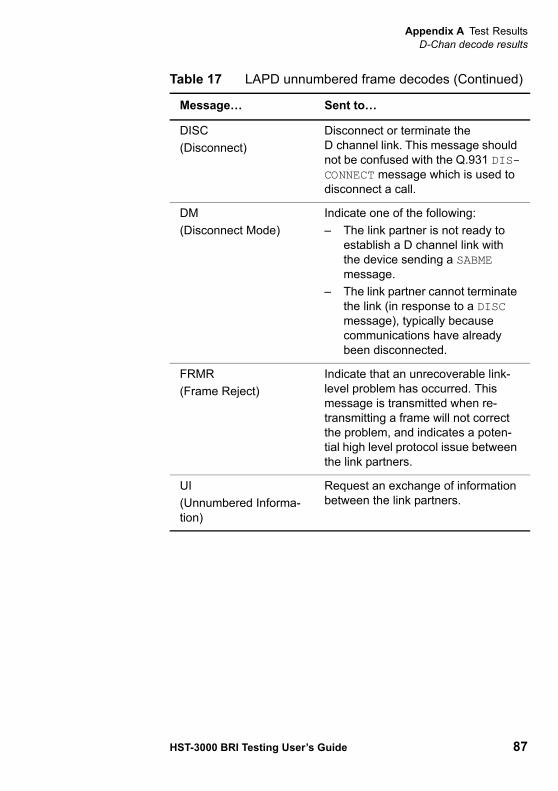
Appendix A Test ResultsD-Chan decode results
HST-3000 BRI Testing User’s Guide 87
DISC(Disconnect)
Disconnect or terminate the D channel link. This message should not be confused with the Q.931 DIS-CONNECT message which is used to disconnect a call.
DM(Disconnect Mode)
Indicate one of the following:– The link partner is not ready to
establish a D channel link with the device sending a SABME message.
– The link partner cannot terminate the link (in response to a DISC message), typically because communications have already been disconnected.
FRMR(Frame Reject)
Indicate that an unrecoverable link-level problem has occurred. This message is transmitted when re-transmitting a frame will not correct the problem, and indicates a poten-tial high level protocol issue between the link partners.
UI(Unnumbered Informa-tion)
Request an exchange of information between the link partners.
Table 17 LAPD unnumbered frame decodes (Continued)
Message… Sent to…

Appendix A Test ResultsD-Chan decode results
88 HST-3000 BRI Testing User’s Guide
LAPDSupervisory
framemessages
Table 18 lists each of the LAPD supervisory frame decode messages. For an overview of LAPD messages, see “LAPD messages” on page 59.
Table 18 LAPD supervisory frame decodes
Message… Sent to…
RR(Receiver Ready)
Keep the signal alive between the link partners, and acknowledge receipt of frames. RR messages are the most common messages observed in D channel decodes. When there are no call-related messages to send, the link partners transmit RR frames to make sure the link stays in service.NOTE: When you are viewing a large number of decode messages to trou-bleshoot call processing, you can typi-cally ignore the RR messages since they are simply used to keep the D channel signal alive.
RNR(Receiver Not Ready)
Indicate that a link partner is experi-encing difficulty (such as buffer deple-tion), and cannot accept any additional information frames (call related mes-sages) at this time. RNR messages should occur rarely, and should be investigated immediately when they occur.
REJ(Reject)
Force re-transmission of bad frames. Frequent REJ frames indicate miscom-munication on the D channel, typically due to errored frames during transmis-sion.

Appendix A Test ResultsD-Chan decode results
HST-3000 BRI Testing User’s Guide 89
Q.931messages
Table 19 lists each of the Q.931 decode messages. For an overview of Q.931 messages, see “Q.931 messages” on page 60.
Table 19 Q.931 decodes
Message… Sent to…
SETUP Originate a call.
CALLPROCEEDING
Indicate that a SETUP message has been received, and that the device is attempting to process the call.
ALERTING Indicate that a SETUP message has been received, and that the device is attempting to process the call.
CONNECT Indicate that the call has been com-pleted and that the calling party is connected with the called party.
CONNECT ACK Acknowledge that the CONNECT mes-sage has been received.
DISCONNECT Disconnect the call. Can be sent from the calling device or the called device.NOTE: DISCONNECT messages report the cause for the disconnection.
RELEASE Release the call in response to aDISCONNECT message, or because a call cannot be connected.NOTE: If a call cannot be connected, and as a result a RELEASE message is issued in response to a SETUP request, the RELEASE message will report the cause for the disconnection.
RELEASECOMPLETE
Acknowledge that a RELEASE mes-sage has been received, and discon-nect the call.NOTE: A call is not disconnected until the RELEASE COMPLETE message is observed.
Appendix A Test ResultsQ.931 Cause Values
90 HST-3000 BRI Testing User’s Guide
Q.931 Cause ValuesCause values indicating the reason a call is disconnected are displayed on the D Channel Decode Results screen and the Call 1/Call 2 Results screen.
For each disconnected call, the D Channel Decode Results screen displays the following cause value information in either the DISCONNECT or RELEASE message:
– A location code, indicating where the disconnect origi-nated (for example, on a private network or a transit network).
– A class code, indicating the type of disconnect (for example, due to a protocol error).
– The cause value issued by the ISDN Network. This value corresponds to a Q.931 cause code (see the cause codes listed in Table 20 on page 91).
– An abbreviated description indicating the reason the call was disconnected.
The Call 1/Call 2 Results screen simply provides the cause value and an abbreviated description of the cause of the disconnect.
NOTE:The cause codes listed in Table 20 on page 91 do not appear on the D Channel Decode Results or Call 1/Call 2 Results screens. The codes correspond to those listed in the International Telecommunications Union (ITU) Q.931 standards.

Appendix A Test ResultsQ.931 Cause Values
HST-3000 BRI Testing User’s Guide 91
Table 20 lists and explains the most commonly encountered cause codes for ISDN BRI calls.
Table 20 Common Q.931 Cause Codes
CauseCode
D Channel Decode Description
Call 1/Call 2 Description
TypicallyIndicates
16 Normal clearing NORMAL CALL CLEARING
No fault is detected; the call is finished.
18 No userresponding
NO USER RESPONSE The receiving equipment did not respond to the call attempt within the allowed time.
28 Invalid number format
INVALID NUMBER FORMAT
The receiving equipment consid-ers the number to be incomplete or in an incorrect format. For example, num-bers sent as a sub-scriber plan are expected to be 7 digits or less; num-bers sent as national dialing plans are expected to be more than 7 digits.
31 Normal unspecified
NORMALUNSPECIFIED
Any number of unspecified condi-tions, but may indi-cate the call is terminating into a “fast busy” (all trunks are busy).
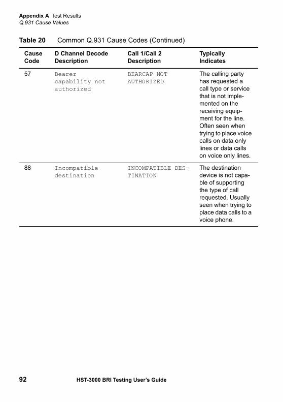
Appendix A Test ResultsQ.931 Cause Values
92 HST-3000 BRI Testing User’s Guide
57 Bearer capability not authorized
BEARCAP NOT AUTHORIZED
The calling party has requested a call type or service that is not imple-mented on the receiving equip-ment for the line. Often seen when trying to place voice calls on data only lines or data calls on voice only lines.
88 Incompatibledestination
INCOMPATIBLE DES-TINATION
The destination device is not capa-ble of supporting the type of call requested. Usually seen when trying to place data calls to a voice phone.
Table 20 Common Q.931 Cause Codes (Continued)
CauseCode
D Channel Decode Description
Call 1/Call 2 Description
TypicallyIndicates
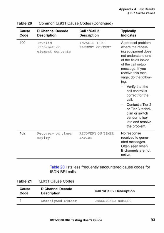
Appendix A Test ResultsQ.931 Cause Values
HST-3000 BRI Testing User’s Guide 93
Table 20 lists less frequently encountered cause codes for ISDN BRI calls.
100 Invalid informationelement contents
INVALID INFOELEMENT CONTENT
A protocol problem where the receiv-ing equipment does not understand one of the fields inside of the call setup message. If you receive this mes-sage, do the follow-ing:– Verify that the
call control is correct for the call.
– Contact a Tier 2 or Tier 3 techni-cian or switch vendor to iso-late and resolve the problem.
102 Recovery on timer expiry
RECOVERY ON TIMER EXPIRY
No response received to gener-ated messages. Often seen when B channels are not active.
Table 20 Common Q.931 Cause Codes (Continued)
CauseCode
D Channel Decode Description
Call 1/Call 2 Description
TypicallyIndicates
Table 21 Q.931 Cause Codes
CauseCode
D Channel Decode Description Call 1/Call 2 Description
1 Unassigned Number UNASSIGNED NUMBER

Appendix A Test ResultsQ.931 Cause Values
94 HST-3000 BRI Testing User’s Guide
2 No route to specified network
NO ROUTE TO TRANSIT NETWORK
3 No route to destination
NO ROUTE TO DESTINATION
6 Channel unacceptable CHANNEL IS UNACCEPTABLE
7 Call awarded delivered in est. ch.
CALL AWARDED
17 User busy USER BUSY
19 User alerting no answer
ALERTING BUT NO ANSWER
22 Number changed NUMBER CHANGED
26 Non-selected user clearing
NON-SELECTED USER CLEARING
27 Destination out of order
DESTINATION OUT OF ORDER
29 Requested facility rejected
REQUEST FACILITY REJECTED
30 Response to STATUS ENQuiry
RESPONSE TO STATUS ENQUIRY
34 No channel available NO CIRCUIT/CHAN AVAILABLE
35 Queued QUEUED
38 NETWORK OUT OF ORDER
41 Temporary failure TEMPORARY FAILURE
42 Network congestion NETWORK CONGESTION
43 Access information discarded
ACCESS INFO DISCARDED
Table 21 Q.931 Cause Codes (Continued)
CauseCode
D Channel Decode Description Call 1/Call 2 Description
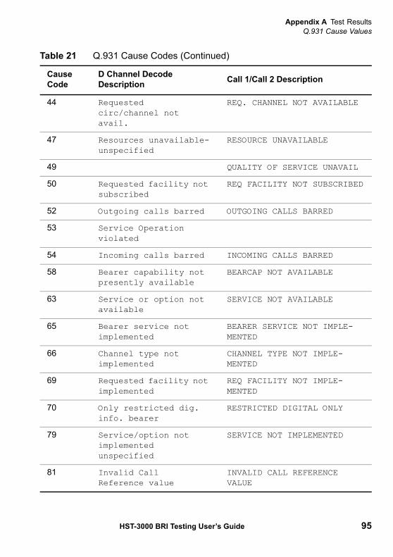
Appendix A Test ResultsQ.931 Cause Values
HST-3000 BRI Testing User’s Guide 95
44 Requested circ/channel not avail.
REQ. CHANNEL NOT AVAILABLE
47 Resources unavailable-unspecified
RESOURCE UNAVAILABLE
49 QUALITY OF SERVICE UNAVAIL
50 Requested facility not subscribed
REQ FACILITY NOT SUBSCRIBED
52 Outgoing calls barred OUTGOING CALLS BARRED
53 Service Operation violated
54 Incoming calls barred INCOMING CALLS BARRED
58 Bearer capability not presently available
BEARCAP NOT AVAILABLE
63 Service or option not available
SERVICE NOT AVAILABLE
65 Bearer service not implemented
BEARER SERVICE NOT IMPLE-MENTED
66 Channel type not implemented
CHANNEL TYPE NOT IMPLE-MENTED
69 Requested facility not implemented
REQ FACILITY NOT IMPLE-MENTED
70 Only restricted dig. info. bearer
RESTRICTED DIGITAL ONLY
79 Service/option not implementedunspecified
SERVICE NOT IMPLEMENTED
81 Invalid Call Reference value
INVALID CALL REFERENCE VALUE
Table 21 Q.931 Cause Codes (Continued)
CauseCode
D Channel Decode Description Call 1/Call 2 Description
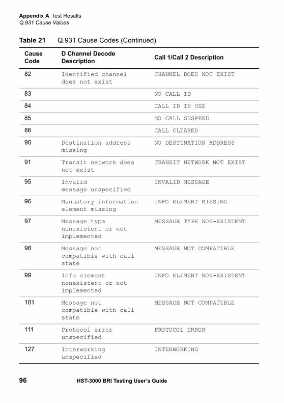
Appendix A Test ResultsQ.931 Cause Values
96 HST-3000 BRI Testing User’s Guide
82 Identified channel does not exist
CHANNEL DOES NOT EXIST
83 NO CALL ID
84 CALL ID IN USE
85 NO CALL SUSPEND
86 CALL CLEARED
90 Destination address missing
NO DESTINATION ADDRESS
91 Transit network does not exist
TRANSIT NETWORK NOT EXIST
95 Invalid message unspecified
INVALID MESSAGE
96 Mandatory information element missing
INFO ELEMENT MISSING
97 Message type nonexistent or not implemented
MESSAGE TYPE NON-EXISTENT
98 Message notcompatible with call state
MESSAGE NOT COMPATIBLE
99 Info element nonexistent or not implemented
INFO ELEMENT NON-EXISTENT
101 Message not compatible with call state
MESSAGE NOT COMPATIBLE
111 Protocol error unspecified
PROTOCOL ERROR
127 Interworking unspecified
INTERWORKING
Table 21 Q.931 Cause Codes (Continued)
CauseCode
D Channel Decode Description Call 1/Call 2 Description
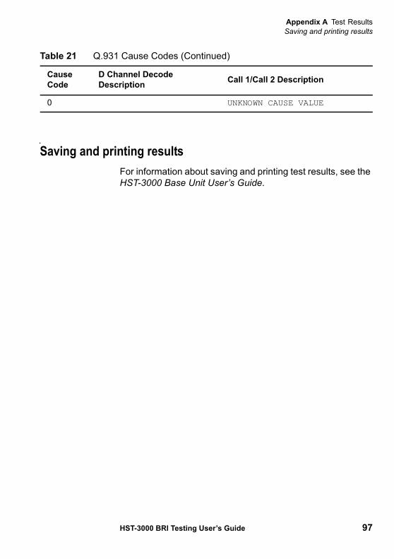
Appendix A Test ResultsSaving and printing results
HST-3000 BRI Testing User’s Guide 97
Saving and printing resultsFor information about saving and printing test results, see the HST-3000 Base Unit User’s Guide.
0 UNKNOWN CAUSE VALUE
Table 21 Q.931 Cause Codes (Continued)
CauseCode
D Channel Decode Description Call 1/Call 2 Description

Appendix A Test ResultsSaving and printing results
98 HST-3000 BRI Testing User’s Guide

B
HST-3000 BRI Testing User’s Guide 99
Appendix BBERT Patterns
This appendix describes the patterns available for BER testing. Topics discussed in this appendix include the following:
– “BERT patterns” on page 100

Appendix B BERT PatternsBERT patterns
100 HST-3000 BRI Testing User’s Guide
BERT patternsTable 22 shows the BERT patterns available for ISDN BRI testing.
Table 22 ISDN BERT patterns
Pattern Description
All Ones Provides a fixed test pattern of all ones. Generally this pattern is used to stress span repeater current regulator circuits. It can also be used as an AIS in unframed circuits, a keep alive signal, or an idle code.
All Zeros Provides a fixed test pattern of all zeros.
Delay Used for measuring round trip delay. Delay pattern measure-ment requires a transmitter/receiver loopback, with the transmit rate equal to the receive rate. This test measures round trip delay once per second (or until the previous delay measurement is complete) for the length of the test, provided pattern sync is present. Normal BER test results (such as bit errors and pattern sync) are not available during delay testing.
511 Selects the 2 9 -1 Pseudorandom pattern, which generates a maximum of 7 sequential 0s and 9 sequential 1s.
2047 Selects the 211 -1 Pseudorandom pattern, which generates a maximum of 10 sequential 0s and 11 sequential 1s. Simulates live data for circuits 56 kbps and lower.
2^15-1 Selects the 215-1 pseudorandom pattern, which generates a maximum of 14 sequential 0s and 15 sequential 1s. Simulates live data for 56 kbps to 2Mbps circuits.
2^20-1 Selects the 220 -1 pseudorandom pattern, which generates a maximum of 19 sequential 0s and 20 sequential 1s. Simulates live data.
2^23-1 Selects the 223 -1 pseudorandom pattern, which generates a maximum of 22 sequential 0s and 23 sequential 1s.
User Bit Pattern Selects a user-defined pattern from 3 to 32 bits long.

C
HST-3000 BRI Testing User’s Guide 101
Appendix CSpecifications
This appendix contains specifications for the BRI testing option. Topics discussed in this appendix include the following:
– “Interface” on page 102– “Test configurations” on page 102

Appendix C SpecificationsInterface
102 HST-3000 BRI Testing User’s Guide
InterfaceThis section describes interface specifications.
Test configurationsThis section describes configurations available for BRI testing.
BRI testingconfigurations
Table 24 lists specifications for BRI testing option configura-tions.
Table 23 Interface specifications
Parameter Specification
Line interface 2B1Q per ANSI T1.601 (1992), providing 0 dB, 2 dB, 4 dB, 6 dB line build-out.
PS1 At least 28 volts is present on the line.
PS2 At least 36 volts is present on the line.
Maximum voltage 42 V +3 V
Table 24 BRI configuration specifications
Parameter Specification
Operating modes Terminate, Monitor
Tests Bit error rate test (BERT)
Error types Frame, CRC, FEBE
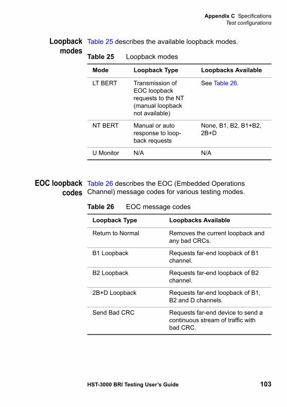
Appendix C SpecificationsTest configurations
HST-3000 BRI Testing User’s Guide 103
Loopbackmodes
Table 25 describes the available loopback modes.
EOC loopbackcodes
Table 26 describes the EOC (Embedded Operations Channel) message codes for various testing modes.
Table 25 Loopback modes
Mode Loopback Type Loopbacks Available
LT BERT Transmission of EOC loopback requests to the NT (manual loopback not available)
See Table 26.
NT BERT Manual or auto response to loop-back requests
None, B1, B2, B1+B2, 2B+D
U Monitor N/A N/A
Table 26 EOC message codes
Loopback Type Loopbacks Available
Return to Normal Removes the current loopback and any bad CRCs.
B1 Loopback Requests far-end loopback of B1 channel.
B2 Loopback Requests far-end loopback of B2 channel.
2B+D Loopback Requests far-end loopback of B1, B2 and D channels.
Send Bad CRC Requests far-end device to send a continuous stream of traffic with bad CRC.

Appendix C SpecificationsTest configurations
104 HST-3000 BRI Testing User’s Guide

HST-3000 BRI Testing User’s Guide 105
Glossary
B
Base Unit — The HST-3000 base unit houses the keypad, display screen, battery, and some connectors. Service inter-face modules (SIMs) connect to the base unit to provide testing functionality.
B-Channel — Bearer Channel. Portion of the BRI interface that typically carries information. See Circuit mode calls.
BERT — Bit Error Rate Test. A known pattern of bits is trans-mitted, and errors received are counted to figure the BER. The Bit Error Rate test is used to measure transmission quality.
BRI — Basic Rate Interface. An ISDN configuration which consists of two B-channels that
can carry voice or data at rate of 64Kbps, and one D-channel, which carries call-control infor-mation.
BRI interface — The interface spanning both the U interface (central office side) and the S/T interface (customer premises side) of the network.
C
Cause Code — Reason an ISDN call was disconnected.
Circuit mode calls — Calls placed on the B channels of the BRI interface.
CRC — Cyclic Redundancy Check. A code word used to confirm that a bit stream contains valid data.
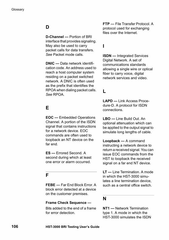
Glossary
106 HST-3000 BRI Testing User’s Guide
D
D-Channel — Portion of BRI interface that provides signaling. May also be used to carry packet calls for data transfers. See Packet mode calls.
DNIC — Data network identifi-cation code. An address used to reach a host computer system residing on a packet switched network. A DNIC is often used as the prefix that identifies the RPOA when dialing packet calls. See RPOA.
E
EOC — Embedded Operations Channel. A portion of the ISDN signal that contains instructions for a network device. EOC commands are often used to loopback an NT device on the far end.
ES — Errored Second. A second during which at least one error or alarm occurred.
F
FEBE — Far End Block Error. A block error detected at a device on the customer premises.
Frame Check Sequence —Bits added to the end of a frame for error detection.
FTP — File Transfer Protocol. A protocol used for exchanging files over the Internet.
I
ISDN — Integrated Services Digital Network. A set of communications standards allowing a single wire or optical fiber to carry voice, digital network services and video.
L
LAPD — Link Access Proce-dure-D. A protocol for ISDN connections.
LBO — Line Build Out. An optional attenuation which can be applied to the output signal to simulate long lengths of cable.
Loopback — A command instructing a network device to return a received signal. You can issue EOC commands from the HST to loopback the received signal on a far end NT device.
LT — Line Termination. A mode in which the HST-3000 simu-lates a line termination device, such as a central office switch.
N
NT1 — Network Termination type 1. A mode in which the HST-3000 simulates the ISDN
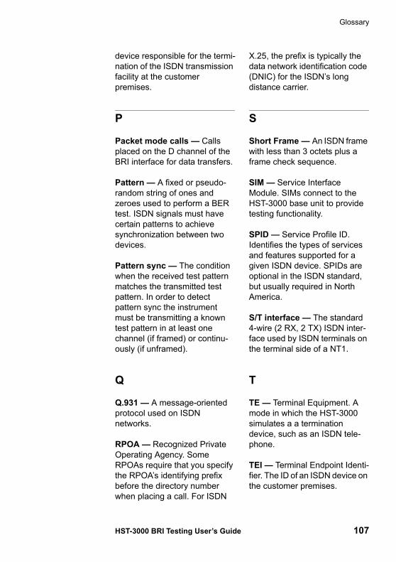
Glossary
HST-3000 BRI Testing User’s Guide 107
device responsible for the termi-nation of the ISDN transmission facility at the customer premises.
P
Packet mode calls — Calls placed on the D channel of the BRI interface for data transfers.
Pattern — A fixed or pseudo-random string of ones and zeroes used to perform a BER test. ISDN signals must have certain patterns to achieve synchronization between two devices.
Pattern sync — The condition when the received test pattern matches the transmitted test pattern. In order to detect pattern sync the instrument must be transmitting a known test pattern in at least one channel (if framed) or continu-ously (if unframed).
Q
Q.931 — A message-oriented protocol used on ISDN networks.
RPOA — Recognized Private Operating Agency. Some RPOAs require that you specify the RPOA’s identifying prefix before the directory number when placing a call. For ISDN
X.25, the prefix is typically the data network identification code (DNIC) for the ISDN’s long distance carrier.
S
Short Frame — An ISDN frame with less than 3 octets plus a frame check sequence.
SIM — Service Interface Module. SIMs connect to the HST-3000 base unit to provide testing functionality.
SPID — Service Profile ID. Identifies the types of services and features supported for a given ISDN device. SPIDs are optional in the ISDN standard, but usually required in North America.
S/T interface — The standard 4-wire (2 RX, 2 TX) ISDN inter-face used by ISDN terminals on the terminal side of a NT1.
T
TE — Terminal Equipment. A mode in which the HST-3000 simulates a a termination device, such as an ISDN tele-phone.
TEI — Terminal Endpoint Identi-fier. The ID of an ISDN device on the customer premises.

Glossary
108 HST-3000 BRI Testing User’s Guide
U
U interface — The physical 2-wire echo cancelling interface spanning the local loop and the customer premises.
U Loss Pad Insertion — An optional attenuation which can be applied to the output signal to simulate long lengths of cable.

HST-3000 BRI Testing User’s Guide 109
Index
AAccepting calls 38Accessing configuration menus 14Alarm LED 8Audio headset, using to insert voice traffic 41–42
BB channel
inserting voice traffic 41performing BERT analysis 42–46
Base unitdefined 105user’s guide xi
Batt LED 9BER testing
ISDN BRI calls 42–46physical layer 52–57
BERT (IDSL) LT mode, illustrated 7BERT patterns 99–100BERT results 77BRI
interface, illustrated 7interfaces, illustrated 4–7
ISDN NT1 emulation mode 7testing configurations 102
CCall 1/Call 2 results 83Calls
accepting 38BERT analysis 42–46Call 1/Call 2 results 83call reference numbers 59disconnecting 39idle 42ignoring 39inserting voice traffic 41–42interpreting D channel decode text 57placing circuit 16–25placing packet 25–33placing self 33–37receiving 38rejecting 39states 83transmitting DTMF tones 40viewing cause codes 41
Cause codesdescribed 90viewing 41

Index
110 HST-3000 BRI Testing User’s Guide
Clearingdecode message buffer 61history test results 62, 63statistical test results 62
Compliance information xiConfiguration menus, accessing 14Connectors 10Conventions xiiiCRC errors, inserting 46
DD channel decode messages
call reference numbers 59capturing to .txt file 62clearing the message buffer 61determining source of 58interpreting 57LAPD supervisory frames 88LAPD unnumbered frames 86Q.931 frames 89sample message 58viewing and navigating 60viewing number captured 61
Data LED 8Decode results 85Decode text
call reference numbers 59capturing messages to .txt file 62clearing the message buffer 61determining source of 58interpreting 57LAPD supervisory frame de-codes 88LAPD unnumbered frame de-codes 86Q.931 decodes 89sample message 58viewing and navigating 60viewing number of messages captured 61
Disconnecting calls 39Documentation, base unit user’s guide xiDTMF tones, transmitting 40
EEmulating NT1 on BRI interface 49–51Emulation modes, illustrated 4–7EOC loopback codes 103Error LED 8Errors
BERT analysis of a call 42BERT analysis of physical layer 52inserting CRC and FEBE 46, 52
FFeatures, ISDN BRI 2FEBE errors, inserting 46
HHeadset, using to insert voice traffic 41–42History test results, clearing 63HST emulation modes 4–7
IIdle calls
BERT 45voice 42
Ignoring calls 39Inserting voice traffic into calls 41–42Interface results 73Interfaces, BRI 4–7Interpreting D channel decode messages 57ISDN BRI
connectors 10D channel decode message de-scriptions 86features 2line specifications 102
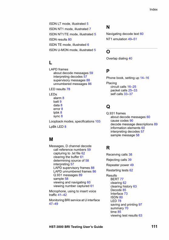
Index
HST-3000 BRI Testing User’s Guide 111
ISDN LT mode, illustrated 5ISDN NT1 mode, illustrated 7ISDN NT1/TE mode, illustrated 5ISDN results 80ISDN TE mode, illustrated 6ISDN U-MON mode, illustrated 5
LLAPD frames
about decode messages 59interpreting decodes 57supervisory messages 88unnumbered messages 86
LED results 78LEDs
alarm 8batt 9data 8error 8lpbk 8sync 8
Loopback modes, specifications 103LpBk LED 8
MMessages, D channel decode
call reference numbers 59capturing to .txt file 62clearing the buffer 61determining source of 58interpreting 57LAPD supervisory frames 88LAPD unnumbered frames 86Q.931 messages 89sample 58viewing and navigating 60viewing number captured 61
Microphone, using to insert voice traffic 41–42Monitoring BRI service at U interface 47–49
NNavigating decode text 60NT1 emulation 49–51
OOverlap dialing 40
PPhone book, setting up 14–16Placing
circuit calls 16–25packet calls 25–33self calls 33–37
QQ.931 frames
about decode messages 60cause codes 90decode message descriptions 89information elements 60interpreting decodes 57sample message 58
RReceiving calls 38Rejecting calls 39Repeater power 49Restarting tests 62Results
BERT 77clearing 62clearing history 63Decode 85Interface 73ISDN 80LED 78saving and printing 97summary 70time 85viewing test results 63
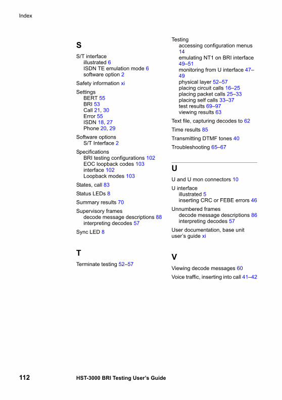
Index
112 HST-3000 BRI Testing User’s Guide
SS/T interface
illustrated 6ISDN TE emulation mode 6software option 2
Safety information xiSettings
BERT 55BRI 53Call 21, 30Error 55ISDN 18, 27Phone 20, 29
Software optionsS/T Interface 2
SpecificationsBRI testing configurations 102EOC loopback codes 103interface 102Loopback modes 103
States, call 83Status LEDs 8Summary results 70Supervisory frames
decode message descriptions 88interpreting decodes 57
Sync LED 8
TTerminate testing 52–57
Testingaccessing configuration menus 14emulating NT1 on BRI interface 49–51monitoring from U interface 47–49physical layer 52–57placing circuit calls 16–25placing packet calls 25–33placing self calls 33–37test results 69–97viewing results 63
Text file, capturing decodes to 62Time results 85Transmitting DTMF tones 40Troubleshooting 65–67
UU and U mon connectors 10U interface
illustrated 5inserting CRC or FEBE errors 46
Unnumbered framesdecode message descriptions 86interpreting decodes 57
User documentation, base unit user’s guide xi
VViewing decode messages 60Voice traffic, inserting into call 41–42


Communications Test and Measurement Regional Sales
North AmericaToll Free: 1 800 638 2049Tel: +1 240 404 2999Fax:+1 240 404 2195
Latin AmericaTel: +55 11 5503 3800Fax:+55 11 5505 1598
Asia PacificTel: +852 2892 0990Fax:+852 2892 0770
EMEATel: +49 7121 86 2222Fax:+49 7121 86 1222
www.jdsu.com
21109871-002Revision 000, 01/2011English