humidity control in the humid south
TRANSCRIPT

Humidity Control in theHumid SouthConference Paper - 930216-Nov-1993Joseph Lstiburek
Abstract:
Humidity concerns in the southern humid climates are particularly difficult to resolve. This is because
one of the most effective approaches to dealing with humidity in heating climates, ventilation, can cause
major humidity problems in the humid south. The issue becomes even more complex when you realize
that you can replace the word humidity in the previous sentences with the words "indoor air quality "
and not change the meaning or impact. Dilution is often used as the solution to indoor pollution in
heating climates. Unfortunately, in humid, air conditioning climates, the greater the rate of dilution,
ventilation or air change, the greater the rate of moisture entry with the exterior air. Therefore, the
greater the likelihood of mold and other biological growth problems, particularly if the moisture in this
incoming air is not removed.
building science.com© 2008 Building Science Press All rights of reproduction in any form reserved.

BETEC Workshop Proceedings November 16-17, 1993
Humidity Control in the Humid South 1
Humidity Control in the Humid SouthJoseph W. Lstiburek, P.Eng.
Humidity concerns in the southern humid climates are particularly difficult to resolve. This is because one of themost effective approaches to dealing with humidity in heating climates, ventilation, can cause major humidityproblems in the humid south. The issue becomes even more complex when you realize that you can replace theword humidity in the previous sentences with the words "indoor air quality " and not change the meaning orimpact. Dilution is often used as the solution to indoor pollution in heating climates. Unfortunately, in humid, airconditioning climates, the greater the rate of dilution, ventilation or air change, the greater the rate of moistureentry with the exterior air. Therefore, the greater the likelihood of mold and other biological growth problems,particularly if the moisture in this incoming air is not removed.
Air conditioning buildings (mechanical cooling) is the major source of both humidity and indoor air qualityconcerns in the humid south. When exterior hot, humid air is cooled its relative humidity is increased. If it iscooled sufficiently, condensation occurs. High relative humidities and condensation can lead to mold and otherbiological growth. Interior relative humidities at surfaces and within building cavities need to be controlled toprevent condensation and biological growth.
An ideal approach to control indoor humidity and indoor air quality in the hot, humid south is to minimize theneed for outside air. The air should be obtained in a controlled manner (mechanically with a fan). The air shouldbe conditioned where it comes into the building. It should be dehumidified by cooling it below its dew point, andused to maintain the enclosure at a slight positive air pressure relative to the exterior. By doing so, it can be usedto control the infiltration of exterior hot, humid air. Furthermore, the building envelope should be built in amanner that aides in the pressurization of the building. Tight construction is recommended. The building enve-lope should also exclude rain, control rain water absorption and control vapor diffusion. Vapor diffusion retardersshould be installed on the exterior of building envelopes in the humid south as compared to the practices innorthern heating climates. Finally, the building envelope should be forgiving so that if it gets wet, it can dry tothe interior. Interior vapor diffusion retarders such as impermeable wall covering should be avoided.
This approach has implications with respect to building envelope tightness and moisture permeability/resistance,air consuming devices, interior activities, interior pollutant source strengths, housekeeping practices, operatingcosts for air conditioning equipment, and air conditioning loads.
Not following this approach has even greater implications with respect to health, safety, comfort, durability,maintenance and affordability.
Mold and Biological Growth ProblemsWhen problems from mold and biological growth do occur in the humid south, they can be divided into threedistinct categories:
• problems on interior surfaces due to elevated levels of moisture in the interior conditioned air (high interiorair relative humidity);
• problems on interior surfaces due to surfaces being too cold leading to high relative humidities at the cooledsurfaces; and
• problems within building cavities due to high cavity moisture levels or moisture passing through buildingcavities causing high relative humidities on material surfaces as the moisture migrates into the conditionedspace
Although these problems can occur independently of each other they often occur in combination. For example,elevated levels of interior moisture are usually due to moisture passing through building cavities from the exte-rior resulting in both cavity moisture problems as well as problems on interior surfaces once the moisture hasgotten into the conditioned space. Overcooling of the space just magnifies both problems thereby creating a third.
CP-9302: Humidity Control in the Humid South

BETEC Workshop Proceedings November 16-17, 1993
Humidity Control in the Humid South 2
Interior Surface Related Problems Due to Elevated Levels of Moisture When interior moisture levels are high,relative humidities at surfaces also are high. Where relative humidities at surfaces are greater than 70 percentmold and other biological growth can occur. In the humid south, the moisture source for these problems is almostalways the exterior air. Moisture must be removed from the air within conditioned spaces such that relativehumidities at surfaces remain below 70 percent. Where conditioned spaces are cooled to 75 degrees Fahrenheit,relative humidities in the air within the space should not exceed 60 percent.
Air which is brought in from the exterior to supply ventilation needs and make-up air needs should be condi-tioned to "dew point 55". In other words, this air should be cooled to at least 55 degrees Fahrenheit in order todehumidify it. At dew point 55, the temperature of the air is 55 degrees Fahrenheit and its relative humidity is100 percent. Once this air is warmed up to 75 degrees Fahrenheit, the temperature of typical air conditionedspaces, its relative humidity will be approximately 50 percent. This air now mixes with the air in the spacediluting/reducing the conditioned space moisture levels/relative humidity. The rate of dilution or mixing isdetermined by meeting the 60 percent relative humidity limit within the conditioned space.
The dehumidification capabilities of air conditioning systems are typically used to remove moisture from the airwithin the conditioned space. Unfortunately, the latent cooling loads (the energy required to cool/remove themoisture in the air) are usually higher than sensible cooling loads in the humid south. This means that air condi-tioning systems should be sized for their latent loads, rather than their sensible loads. Sizing of equipmentbecomes critical. Undersizing of air conditioning equipment can lead to to obvious comfort and humidity prob-lems. However, oversizing of air conditioning equipment can also lead to high interior humidity problems sinceoversized equipment will not operate as often, and therefore will dehumidify less than properly sized equipment.
Concerns about energy conservation has lead to the development of energy efficient mechanical cooling systems.Unfortunately, this has also reduced the ability of many of these systems to dehumidify air. In many cases, theexterior air is not cooled sufficiently to remove sufficient quantities of moisture.
Air cooled to 55 degrees Fahrenheit is usually too cold to introduce into a space. In the past this cooled air washeated after it was cooled ("reheat") prior to use. Reheat results in a significant energy penalty, and is not allowedin many jurisdictions for this reason. To avoid reheat requirements, some systems do not cool air down to "dewpoint 55". Unfortunately, this can result in insufficient moisture removal and subsequent high interior moisturelevels.
Two approaches have been successfully used to address the issue of reheat. One is a new technology: heat pipeheat recovery. The other dates back to the 1930's and has been recently "rediscovered": run-around coils. Both ofthese approaches use heat removed during the mechanical cooling process to "reheat" the cooled air once it hasshed its moisture thereby reducing the energy penalty of standard reheat.
Interior Surface Related Problems Due to Overcooling of SurfacesWhen surfaces become too cold, surface relative humidities rise above 70 percent. When they rise to 100 percent,condensation occurs. If air conditioned air is supplied at too low a temperature, the diffusers can be extremelycold leading to condensation ("sweating"). Where diffusers are located poorly or adjusted incorrectly, cold airmay be "blown" against surfaces creating cold spots and localized areas of high relative humidity and moldgrowth.
Supply ducts enclosed in interior walls and dropped ceilings often are not sealed and leak supply air. This supplyair is typically under substantial positive air pressure and the resulting "jet" of air can "blow" against a surfaceleading to localized cooling. The cooling happens from the building cavity side, whereas the mold growth usuallyappears on the room side.
In cooling climates, condensing surfaces of exterior walls are typically the interior gypsum board. If interiorspaces are "overcooled", the interior surfaces fall below the dew point temperature of the exterior air and conden-sation occurs. Figure 1 illustrates the case of a wall experiencing condensation as a result of overcooling. Byraising the interior conditioned space temperature, the temperature of the first condensing surface is raised.Consequently, as the graph in Figure 1 shows, the potential for condensation is eliminated in this climate.
CP-9302: Humidity Control in the Humid South

BETEC Workshop Proceedings November 16-17, 1993
Humidity Control in the Humid South 3
Figure 2 illustrates the case of a wall experiencing condensation as a result of diffusion in a particularly severecooling climate (Miami, Florida). By using impermeable rigid insulation (approximately R-7) on the interior ofthe masonry wall, the temperature of the first condensing surface is raised. As shown in the graph in Figure 2,condensation potential is eliminated since the temperature on the exterior face of the rigid insulation (the firstcondensing surface) is above the ambient range throughout the year.
Overcooling of spaces often occurs as a result of ignorance and/or poor design. Most people in the humid southare aware of the fact that the more an air conditioner operates the greater the removal of moisture from theinterior air by the air conditioner. System controls are therefore often adjusted to provide frequent operation ofthe system. To keep systems operating more frequently, thermostat settings are lowered below recommendedlevels. In addition, when systems are oversized, in order to operate for longer periods of time, thermostat settingshave to be lowered resulting in overcooled spaces.
Month
Tem
per
atu
re (
°F)
DEC JAN FEB MAR APR MAY JUN JUL AUG SEP OCT NOV DEC
90
85
80
75
70
65
60
55
50
Mean daily ambientdew point temperature
Potential forcondensation
Temperature ofthe gypsum boardwith interior at 75°F
Temperature ofthe gypsum boardwith interior at 75°F
Masonry block
Brick veneer
1” air space (pressure-equalized rain screen)
Furring strips
Gypsum board
Permeable latex paint
The outside face of thegypsum board is the firstcondensing surface
Figure 1: Potential for condensation in a masonry wall cavity in Tampa, FloridaBy raising the temperature of the interior conditioned space from 70°F, the temperature of the first condensingsurface (the outside surface of the gypsum board is raised above the mean daily ambient dew point temperatureso that no condensation will occur.
Figure 2: Potential for condensation in a masonry wall cavity in Miami, FloridaPlacing rigid insulation on the interior of the masony wall raises the temperature of the first condensing surfaceabove the mean daily ambient dew point temperature so that no condensation will occur. The outside surface ofthe rigid insulation becomes the first condensing surface in this assembly.
Month
Tem
per
atu
re (
°F)
DEC JAN FEB MAR APR MAY JUN JUL AUG SEP OCT NOV DEC
90
85
80
75
70
65
60
55
50
Mean daily ambientdew point temperature
Potential forcondensation
Temperature ofthe gypsum boardwith no rigid insulationat 75°F
Temperature ofexterior surface ofthe rigid insulation
Masonry block
Brick veneer
1” air space (pressure-equalized rain screen)
Furring strips
Gypsum board
Impermeable rigidinsulation
The outside face of therigid insulation is the firstcondensing surface
CP-9302: Humidity Control in the Humid South
© buildingscience.com © buildingscience.com

BETEC Workshop Proceedings November 16-17, 1993
Humidity Control in the Humid South 4
In a final, unfortunate irony, overcooling a space can actually increase latent loads rather than result in a netmoisture removal. Moisture flow is generally from warm to cold. The colder the space the more moisture isdrawn into the space from the exterior.
Building Cavity Moisture ProblemsIn the humid south, moisture flow is typically from the exterior to the interior or from the warm to the cold. If therate of moisture entry into the building envelope from the exterior is greater than the rate of moisture removalfrom the building envelope into the conditioned space, accumulation occurs with building envelope cavities andserious problems result.
The general control strategy for building envelopes in the humid south is quite straightforward. Make it difficultfor moisture to enter the building envelope from the exterior, and make it easy for moisture to leave the buildingenvelope to the interior.
Moisture enters building envelopes from the exterior in the humid south three major ways:
• rain leakage
• air leakage
• vapor diffusion
Controlling these mechanisms means keeping the rain out of the building envelope, keeping exterior air out ofthe building envelope and keeping exterior moisture from vapor diffusion out of the building envelope. Inaddition it also means being realistic about the probability of success at controlling these mechanisms andtherefore providing a means of drying to the interior. In practice, this usually means not preventing the normal/typical drying to the interior conditioned space by installing an impermeable wall covering.
Rain is a particularly severe mechanism of moisture transport in the humid south. When rain wets the exterior ofa building the exterior surfaces typically absorb the rain water. For instance, brick cladding is a powerful rainwater "sponge". Recall that moisture flow is from warm to cold. When wet brick is warmed by the sun, a signifi-cant temperature differential is created. The sun serves to "drive" rain water into a building envelope. If theinterior space is also air conditioned or cooled, the air conditioning serves to "suck" the rain water inwards as aresult of a temperature differential.
The effect of incident solar radiation on a rain saturated cladding is dramatic. Consider that a brick veneer orstucco coating can be readily warmed by the sun well above 120 degrees Fahrenheit. The air contained in anairspace behind a brick veneer can be similarly warmed and can be considered to be at saturated conditions(vapor pressure of 11.74 kPa). This results in an increase of almost 500 percent in the effective exterior vaporpressure (Figure 3). Solar radiation isa powerful force that drives moisturein rain-saturated cladding inwards.This force can be ten times greaterthan the vapor diffusion drivingmoisture outwards under the mosthostile conditions experienced inheating climates.
Exterior sprinklers can excacerbateproblems by wetting exteriorcladdings on a regular basis. Thenormal southern climate temperaturedifferential then serves to move thissprinkler deposited water into theconditioned space.
Masonry block (permeable)
Exterior Conditions
Temperature: 80°FRelative humidity: 75%Vapor pressure: 2.49 kPa
Brick veneer is saturatedwith rainwater
1-in. air space (rain screen,pressure equalized)
Interior Conditions
Temperature: 75°FRelative humidity: 60%Vapor pressure: 1.82 kPa
Conditions within Cavity:
Temperature: 120°FRelative humidity: 100%Vapor pressure: 11.74 kPa
Vapor is driven inward by ahigh vapor pressure differentialbetween the cavity and the interior
Solar radiationstricks wall
Figure 3
CP-9302: Humidity Control in the Humid South
© buildingscience.com
BETEC Workshop Proceedings November 16-17, 1993
Humidity Control in the Humid South 5
Rain water must be prevented from being absorbed by building envelopes. Stucco claddings should be painted/sealed to prevent rain water absorption. Brick veneers should be installed only in conjunction with air barrier/vapor barrier membranes/coatings installed between them and the rest of the building envelope.
Air leakage of exterior humid air into air conditioned building envelopes is being recognized as the major sourceof most of the IAQ moisture related problems in the humid south. For exterior air to be a problem in a buildingenvelope in the humid south, three conditions must be present:
• moisture must be in the air;
• a hole, opening or pathway must exist; and
• a pressure difference must exist which draws the moisture laden air into the hole, opening or pathway.
Examining these three conditions it becomes clear that moisture will almost always be present in the exterior air.Furthermore, holes, openings and pathways will also always be present because it is not possible to ensureperfect workmanship and perfect materials are not available. The only method of controlling air leakage in thehumid south is controlling air pressure differences across building envelopes and within building cavities.
Where problems have occurred, it is because interior conditioned spaces have been at a negative air pressurerelative to the exterior and/or building cavities have been at a negative air pressure relative to the exterior.
Infiltrating humid air will carry moisture into wall and building assemblies. Whether moisture is deposited withinthe assemblies depends on the moisture content of the air and the surface temperature of each material in the wallassembly.
In the humid south, vapor pressure differences between conditioned spaces and the exterior are often greater thanthose typically found in heating climates. For example, the vapor pressure difference between the exterior designdew point temperature in Miami (79 degrees Fahrenheit, 2.49 kPa) and an interior air conditioned space (55degree Fahrenheit dew point temperature, 1.50 kPa) is 0.97 kPa. In Minneapolis, with a heating design tempera-ture of minus 16 degrees Fahrenheit (0.06 kPa) and an interior space conditioned to 70 degrees Fahrenheit at 35percent relative humidity (0.93 kPa), the vapor pressure difference is 0.87 kPa. The cooling climate vaporpressure difference is 15 percent larger than the vapor pressure difference in the heating climate. While thecooling climate vapor pressures are more significant, measures to control vapor diffusion are more commonlyaccepted by the building community in heating climates.
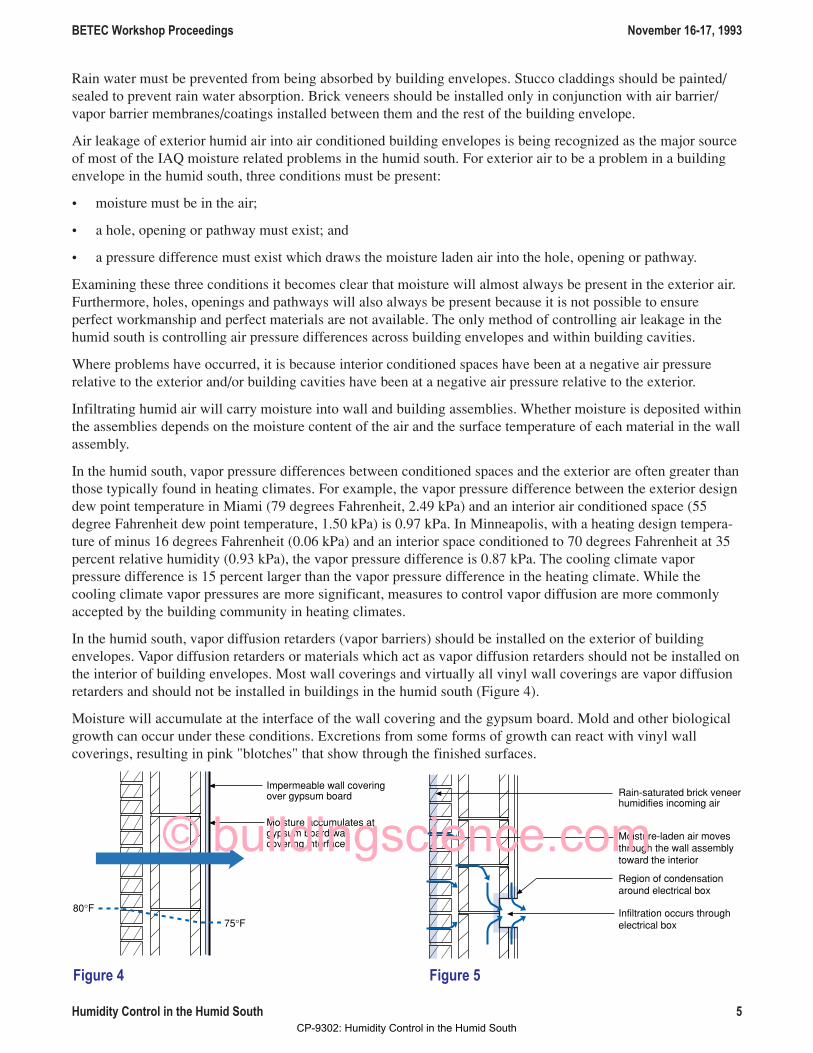
In the humid south, vapor diffusion retarders (vapor barriers) should be installed on the exterior of buildingenvelopes. Vapor diffusion retarders or materials which act as vapor diffusion retarders should not be installed onthe interior of building envelopes. Most wall coverings and virtually all vinyl wall coverings are vapor diffusionretarders and should not be installed in buildings in the humid south (Figure 4).
Moisture will accumulate at the interface of the wall covering and the gypsum board. Mold and other biologicalgrowth can occur under these conditions. Excretions from some forms of growth can react with vinyl wallcoverings, resulting in pink "blotches" that show through the finished surfaces.
80°F75°F
Moisture accumulates atgypsum board/wallcovering interface
Impermeable wall coveringover gypsum board
Figure 4
Infiltration occurs throughelectrical box
Moisture-laden air movesthrough the wall assemblytoward the interior
Region of condensationaround electrical box
Rain-saturated brick veneerhumidifies incoming air
Figure 5
CP-9302: Humidity Control in the Humid South
© buildingscience.com

BETEC Workshop Proceedings November 16-17, 1993
Humidity Control in the Humid South 6
Where air movement and vapor diffusion both occur, air movement tends to dominate vapor diffusion and has asignificantly greater effect on moisture transfer into building assemblies than vapor diffusion alone.
Figure 5 illustrates the effect of infiltrating air through an electrical outlet box in a concrete masonry block wallassembly. The effect of air leakage on the wetting of the wall assembly is significantly magnified as a result ofrain wetting the exterior cladding. The rain-saturated building elements "humidify" the infiltrating air as it passesthrough, over, or around them.
Ventilation and Make-up AirThe minimum requirements for outside air should be set by applying ASHRAE Standard 62-1989. Unfortunately,for many buildings in the humid south, this requirement will likely be far in excess of what has been typicalpractice. Most existing facilities do not have the cooling capability to handle the sensible and latent loads im-posed by meeting ASHRAE Standard 62-1989. In new facilities, the cooling capacity will be present as they willprobably have been designed to meet ASHRAE Standard 62-1989. However, the operating cost implications offollowing ASHRAE Standard 62-1989 applies pressures on facilities managers to operate the systems at less thanthe recommended minimum outside air.
Since air change or dilution is likely to be limited, source control becomes paramount. Housekeeping practices,occupant activities, interior furnishings and building materials/components are key areas to review with respectto source strength.
The tighter a building envelope or enclosure, the less air required in order to pressurize the conditioned space.Leaky buildings require a great deal of air from the exterior in order to pressurize. The air which is brought infrom the exterior in order to achieve pressurization must be dehumidified and cooled. The more air which isbrought in, the greater the cooling load and the greater the operating cost. It is therefore desirable to build tightbuilding envelopes in order to minimize the amount of air required to provide pressurization.
Many building enclosures have exhaust systems and air consuming devices such as dryers and cook tops whichextract air from a building. This air must be replaced with "make-up" air. If it is not,depressurization of the conditioned space occurs, resulting in the infiltrationof exterior, hot humid air (Figure 6). More air must be mechanicallysupplied to a building, then is extracted under all operatingconditions.
In some facilities, "make-up" air is attempted to be supplied"passively" through packaged terminal air conditioners(PTAC's) or heat pumps (PTHP's). These are the typicalunder window through-the-wall units. The approach iscommon in hotels and motels and involves air extractedfrom a washroom via a central exhaust system. For air to bedrawn into the room through the PTAC or PTHP a negativepressure must exist in the room. The central exhaust systemcreates this negative pressure. Unfortunately, air is alsodrawn into the room through random leakage openings inthe building envelope as well as through the PTAC orPTHP.
Some PTAC and PTHP units supply make-up air with a fan in order to deal with the negative pressure problem ofpassive make-up air openings. Usually this air is supplied only when the unit is operating. The duty cycle (ontime) of these units is typically 20 to 30 percent. However, the central exhaust from the bathroom is usually oncontinuously. In other words 70 to 80 percent of the time make-up air is not being supplied and the conditionedspace is under a negative pressure relative to the exterior. It is necessary to coordinate the exhaust fan operationwith the duty cycle of the PTAC and PTHP units in order for this strategy to work. This is almost impossible tocoordinate, and negative air pressures result.
Rangehood
Clothesdryer
Figure 6
CP-9302: Humidity Control in the Humid South
© buildingscience.com
BETEC Workshop Proceedings November 16-17, 1993
Humidity Control in the Humid South 7
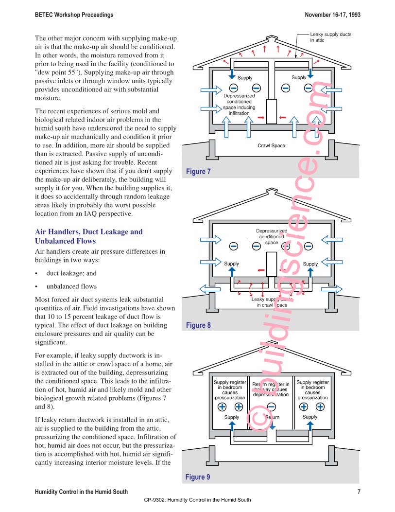
The other major concern with supplying make-upair is that the make-up air should be conditioned.In other words, the moisture removed from itprior to being used in the facility (conditioned to"dew point 55"). Supplying make-up air throughpassive inlets or through window units typicallyprovides unconditioned air with substantialmoisture.
The recent experiences of serious mold andbiological related indoor air problems in thehumid south have underscored the need to supplymake-up air mechanically and condition it priorto use. In addition, more air should be suppliedthan is extracted. Passive supply of uncondi-tioned air is just asking for trouble. Recentexperiences have shown that if you don't supplythe make-up air deliberately, the building willsupply it for you. When the building supplies it,it does so accidentally through random leakageareas likely in probably the worst possiblelocation from an IAQ perspective.
Air Handlers, Duct Leakage andUnbalanced FlowsAir handlers create air pressure differences inbuildings in two ways:
• duct leakage; and
• unbalanced flows
Most forced air duct systems leak substantialquantities of air. Field investigations have shownthat 10 to 15 percent leakage of duct flow istypical. The effect of duct leakage on buildingenclosure pressures and air quality can besignificant.
For example, if leaky supply ductwork is in-stalled in the atttic or crawl space of a home, airis extracted out of the building, depressurizingthe conditioned space. This leads to the infiltra-tion of hot, humid air and likely mold and otherbiological growth related problems (Figures 7and 8).
If leaky return ductwork is installed in an attic,air is supplied to the building from the attic,pressurizing the conditioned space. Infiltration ofhot, humid air does not occur, but the pressuriza-tion is accomplished with hot, humid air signifi-cantly increasing interior moisture levels. If the
Leaky supply ductsin attic
Supply Supply
Depressurizedconditioned
space inducinginfiltration
Crawl Space
Figure 7
Supply Supply
Depressurizedconditioned
space
Leaky supply ductsin crawl space
Figure 8
ReturnSupply Supply
Return register inhallway casues
depressurization
Supply registerin bedroom
causespressurization
Supply registerin bedroom
causespressurization
Figure 9
CP-9302: Humidity Control in the Humid South
© b
uild
ings
cien
ce.c
om

BETEC Workshop Proceedings November 16-17, 1993
Humidity Control in the Humid South 8
moisture removal capability of the cooling system isunable to remove this moisture, mold and other biologi-cal growth also occurs.
Unabalanced flows often occur when supply and returnflows to individual rooms are not equal. This typicallyoccurs when supply air registers are located in bedroomsand a return is located in a hallway. When the bedroomdoors are closed, air is not able to access the return andbedrooms become pressurized and the hallway becomesdepressurized (Figure 9).
A common example of an air pressure related moistureproblem in a hot, humid climate occurs where the airhandler for a forced air cooling system is located in acloset/utility room. A large unsealed opening often existsbetween the supply ductwork, which is located in theattic space, and the ceiling of the closet/utility roomwhere the supply duct penetrates (Figure 10). Return airfor the system is drawn from the hot, humid attic spaceinto the utility room through the opening around theductwork and into the return grill of the air handler.There are cases where the temperature of the air condi-tioned space has actually gone up when the air condi-tioner was turned on in similar installations. The coolingload increase that occurs from drawing the hot, humid airinto the system is actually greater than the capacity of thecooling system. Ductwork should never be installedunless it is sealed airtight with mastic and then tested forleakage.
These principles can be extrapolated to large commercialor institutional facilities with numerous air handlers andduct systems. Now the pressure relationships can becomevery complicated. One zone of a building can becomepressurized, while another zone of a building becomesdepressurized. Furthermore, leakage of ductwork enclosed within building cavities can lead to the depressuriza-tion or pressurization of the cavities themselves. This is very common in hotel and motel facilities where indi-vidual room air handlers with leaky housings are built into exterior corners or built into dropped ceiling locationswhere demising wall cavities are connected directly to exterior walls. It is not unusual to have a room at positiveair pressure relative to the exterior, while the wall cavities are at a negative air pressure relative to the exterior.
Negative air pressure fields in interstitial spaces can extend great distances away from air handling equipmentdue to the perforated nature of most framing systems coupled with electrical, plumbing, and mechanical servic-ing.
When the amounts of supply and return air are the same in a room or a facility, no air pressure differential occurs.Many facilities are "commissioned" by balancing contractors who measure air flows in and out of spaces. Sincetraditional air balancing is limited to the measurement of air flows into and out of supply and return registers, it isineffectual at identifying duct leakage and air pressure relationships in building conditioned spaces and cavities.Zonal air pressure differentials are rarely measured. Furthermore, subtracting the sum of the return flows fromthe sum of the supply flows will not determine quantities of outside air or pressure relationships since ductleakage of the conditioning unit (return/supply) and exhaust ducts is not considered.
Hot attic airis drawnthroughopeningaround
supply ductAir handler is located
in a room withoutadequate provision
for return air
Returngrille
Supplyduct
Attic air is drawnthrough electrical
and plumbingpenetrations and between top plateand gypsum board
connection
Figure 10
CP-9302: Humidity Control in the Humid South
© b
uild
ings
cien
ce.c
om

BETEC Workshop Proceedings November 16-17, 1993
Humidity Control in the Humid South 9
Air pressure relationships should be determined with smoke pencils and digital micromanometers. Relationshipsbetween rooms and the exterior as well as between building cavities and the exterior should be determined. Thesepressure relationships should be determined with air handling equipment on and off as well as with exhaustsystems on and off.
Building mechanical systems can succeed in pressurizing building enclosuresrelative to the exterior with conditioned air. However, duct leakage fromreturn systems and air handlers enclosed in building cavities andservice chases can succeed indepressurizing demising wallsand other interstitial cavities. If these cavities are connectedto the exterior they become pathways for infiltrating hot,humid air. As this air is cooled on its inward journey,moisture can be deposited on the surfaces within thesecavities. Once moisture is deposited on these surfaces,vapor diffusion attempts to pull the moisture into theconditioned spaces. If interior surface finishes retard thisinward migration, serious problems can occur.
Depressurization of entire building enclosures can occurunintentionally through the installation of powered atticexhaust fans (Figure 11). Although these exhaust fans arelocated exterior to the conditioned space, leaky ceilings caneffectively couple attic spaces to interior conditionedspaces.
Recommended Approach to Residential HVAC Systems in the Humid SouthThe choice of heating and cooling approaches limits the choice of mechanical ventilation options and should bemade first. Forced air heating or radiant heating can lead to different mechanical ventilation system requirements.Mechanical cooling is usually provided through a forced air approach and similarly limits possibilities formechanical ventilation systems. The most common approachs involve forced air heating combined with forcedair mechanical cooling or distributed mechanical cooling (split system multiple coils, individual room units suchas packaged terminal air conditioners, PTAC units).
Air change through mechanical ventilation can be utilized during heating periods to control interior moisturelevels. Dehumidification through the use of mechanical cooling (air conditioning) can be utilized during coolingperiods to control interior moisture levels.
Fuel source selection does not impact the approach to space conditioning (forced air or radiant), but does impactthe type of equipment selected. If combustion appliances are selected, they should not be subject to backdraftingor spillage of combustion products.
Only sealed combustion or power vented combustion appliances should be used for space conditioning and/ordomestic hot water. Ideally, combustion appliances should be installed exterior to the conditioned space (in agarage or utility room accessed from the exterior and isolated from the building). Some combustion systemsprovide for the installation of the combustion source exterior to the building envelope, and the associated airhandler within the conditioned space (a fan coil unit located inside the conditioned space and the heat source, agas water heaterl, located in a garage). Gas cook tops and/or ovens should be only installed in conjunction with adirect vented (to the exterior) exhaust range hood. Gas cook tops and/or ovens which can be directly vented arerecommended.
Recirculating range hoods should be avoided due to health concerns. If these devices are not frequently serviced,through cleaning and filter replacement, they become a host for biological growth and a major source of odors.
Avoid unvented combustion appliances. Provide fireplaces with their own air supply (correctly sized) from theexterior as well as tight-fitting glass doors.
Leaky ceiling
Powered atticexhaust fan
Figure 11
CP-9302: Humidity Control in the Humid South
© b
uild
ings
cien
ce.c
om

BETEC Workshop Proceedings November 16-17, 1993
Humidity Control in the Humid South 10
Air handlers should be located within the condi-tioned space with provision for easy access tofaciltitate servicing, filter replacement, drain pancleaning, future upgrading and/or replacement astechnology improves. Hostile locations (extremetemperatures and moisture levels) such as atticsand unconditioned (vented) crawl spaces shouldbe avoided. Equipment located in attics is diffi-cult to access, service and replace. Condensatedrain pans located in attics are rarely cleanedproviding a major source of microbiolgicalgrowth related health concerns and when cloggedcreate a major repair expense if overflowingcondensate damages interior surface finishes.
Floor space within conditioned spaces (insidehomes) should be provided for air handlingequipement such as fan coil units and furnaces.Interior utility rooms are preferred to garagelocations. Garage locations are preferred to atticsand vented crawl spaces. With respect to combus-tion appliances, air handlers are ideally locatedwithin conditioned spaces with the combustion appliance located in a garage (fan coil unit inside, gas waterheater in garage). Duct work connections should be designed with sufficient space to allow upgrading/replace-ment for electronic or HEPA filtration and/or future replacement of air handlers.
Mechanical ventilation should be balanced (stale air exhaust and fresh air suppy), continuous, distributed andtranparent (quiet, inexpensive to operate and service).
The following system satisfies these requirements: a forced air heating/cooling system with a supply fan systemproviding fresh air to the conditioned space used in conjunction with a central exhaust system extracting air frombathrooms and the kitchen (Figure 12).
• stale air exhaust is through the central exhaust system
• fresh air supply is through a supply fan system
• continuous operation during occupancy is met by operational control
• distribution is through the forced air system
In this approach a control strategy (time on/off) for the supply fan system, central exhaust system and air handleris necessary during occupancy. The supply fan system typically only operates during the cooling periods anddoes so on a continuous basis. The central exhaust system typically operates on an intermittent basis duringcooling periods to control odors in bathrooms on an occupant demand basis (timed switches in bathrooms).During heating periods, the central exhaust system typically runs continuously, or on a humidity demand basis(humidistat control, when the interior humidity goes up, the exhaust system turns on). This system is compatiblewith a heat recovery ventilator such as an air-to-air heat exchanger.
The fresh air supplied during air conditioning periods by the supply fan system also serves to pressurize thebuilding enclosure. This supply fan system typically operates continuously under a "summer/cooling" setting,and does not operate at all during the heating season under a "winter/heating" setting.
The fresh air supply is typically ducted to the return side (warm side) of the forced air system via an insulatedduct (to limit condensation). The fresh air is also "preconditioned" to limit condensation by mixing with interiorair (60:40 interior to exterior air ratio or greater) prior to introduction into the return side of the air handling
Supply
Supply fansystem providingfresh air to theconditioned space
Supply
Supply Supply
Return
Return
Airhandlingunit
Unvented, conditionedcrawl spaceSupply
Centralexhaust fan
Exhaust
Exhaust
Exhaust
Figure 12
CP-9302: Humidity Control in the Humid South
© b
uild
ings
cien
ce.c
om

BETEC Workshop Proceedings November 16-17, 1993
Humidity Control in the Humid South 11
system. Stale air is removed through a central exhaust system. Exhaust vents are located in the kitchen andbathrooms.
The central exhaust system operates intermittently under a "summer/cooling" setting, being activated by timedswitches in the bathrooms. Under a "winter/heating" setting the central exhaust system operates eithercontinously (at a low speed setting) or some fraction of time (intermittent operation ventilation approach duringheating) every hour whenever occupants are present. During heating periods it may be desirable to control thecentral exhaust fan high speed setting by a humidity sensor.
The forced air system provides effective distribution of fresh air throughout the house. The overall system shouldbe designed, balanced and commissioned so that positive air pressure relationships are maintained during coolingperiods.
Ventilation RequirementsEnclosures should be ventilated in a controlled maner. During cooling periods controlled ventilation should belimited to minimum levels (unless the exterior ventilation air is preconditioned) to reduce latent cooling loads(exterior humidity brought in with the ventilation air) without compromising indoor air quality. ASHRAE 62-89recommends - 15 cfm per person. When applying this rate to a residence, the design occupancy can be based onthe number of bedrooms. This determines the minimum standard for continuous base rate ventilation for thehouse. It can be assumed that two people sleep in the master bedroom, and one other person sleeps in eachadditional bedroom. The following ventilation requirements result:
• one bedroom house 30 cfm
• two bedroom house 45 cfm
• three bedroom house 60 cfm
• four bedroom house 75 cfm
This minimum base rate ventilation should be continuously distributed throughout the house when the building isoccupied.
Forced Air Ducted SystemsA forced air ducted system, including all duct work, the air handling unit, supply plenum and return plenumshould be considered a closed system. In other words, when all registers and grills are taped shut, no air leakageoccurs. The only place for air to leave the supply duct system and the air handling unit is at the supply registers.The only place for air to enter the return duct system is at the return grills.
The air handling system requires an air barrier/air retarder system similar to that required by the building enve-lope. The materials used to create or seal an air handling system air barrier/air retarder system should have thefollowing characteristics:
• The materials should be healthy and safe with respect to the occupants (flame spread, smoke development,toxicity, off-gasing, aerosolization)
• The materials must be impermeable to the passage of air.
• The material or system of materials used must be continuous.
• The materials must be sufficiently rigid to resist the air pressures and gravity forces which act on them.
• The materials should be durable, maintainable, cleanable and able to last the life of the system.
Duct work can take numerous forms:
ª sheet metal
• fiberglass duct board covered on one side with foil
CP-9302: Humidity Control in the Humid South

BETEC Workshop Proceedings November 16-17, 1993
Humidity Control in the Humid South 12
• insulated plastic flex duct
• intersitial building cavities created by wood framing and gypsum board
In order to create an air barrier/air retarder system out of these duct work materials all openings, penetrations,cracks, holes need to be sealed. The preferred method of sealing these openings is fiberglass mesh and mastic.Tape is not recommended for use on metal, ductboard, flex duct and interstitial building cavity ducts due to itspoor performance and unforgiving nature.
The longitudinal seams and transverse joints in sheet metal ducts and the foil side of fiberglass duct board shouldbe sealed. The inner liner of insulated plastic flex duct should be sealed where flex ducts are connected to otherducts, plenums, junction boxes and boots/registers.
Flex ducts in inaccessibleareas should be avoided asthey are not cleanable withconventional duct cleaningmethods. When flex ducts areused, care must be taken toprevent restricting air flow by"pinching" ducts.
Connections between grills,registers and ducts at ceilings,floors or knee walls typicallyleak where the boot does notseal tightly to the grill or sheetrock. Air from the attic,basement, or crawl space canbe drawn into the return. Leakscan also exist within the bootand where the ducts connect tothe boot. These leakage sitesneed to be sealed with mastic.
Interstitial building cavities areoften used as ducts. A commonexample is a wall cavity usedas a return duct and theassociated leakage. These cavities often leak at the top and bottom plates to gypsum board, horizontally to otherstud bays and at the duct to top or bottom plate connections. Figure 13 describes a method of avoiding such ductleakage which involves coordination between the HVAC installer and the drywaller.
In many instances, it is more difficult to seal building cavities used as ducts, than to fabricate and seal ducts sizedto the cavities. This is particularly the case where floor joist cavities are "panned". In crawlspaces, basements andbetween floors the area between the floor joist is often used as a duct. This is done by panning of the area withsheet metal nailed to the bottom of the joists. The sheet metal is rarely sealed and is very leaky. The connectionbetween the joist and the sub floor is also a large source of leakage. The end of the floor joist duct is also typi-cally capped off with more sheet metal and is also a large source of leakage (Figure 14).
Due to the difficulties in sealing building cavities used as ducts, fabricated sheet metal, duct board or plastic flexducts should be used wherever possible.
When a return plenum draws directly through a wall, the wall cavity may inadvertantly become an intersitialduct. If the penetration through the wall is not blocked and sealed, return leaks can occur when air is drawn fromthe wall cavity (Figure 15). The wall cavity should be isolated from the return.
Return airopening
Returnduct
Returnair
Return duct
Partition wall section Partition wall front view
Continuous bead ofsealant/adhesive bygypsum board installer
Subfloor
Return air diffuser
Wall cavity serves asa return duct
Ceiling gypsumboard
Fabric and masticseal return duct
to top plate
Continuous bead ofsealant/adhesive bygypsum board installer
Figure 13
CP-9302: Humidity Control in the Humid South
© b
uild
ings
cien
ce.c
om
© b
uild
ings
cien
ce.c
om

BETEC Workshop Proceedings November 16-17, 1993
Humidity Control in the Humid South 13
Sometimes return plenums leak through the floor.In floors with crawlspaces or basements, theplenum floor may not be air tight, allowing airfrom those zones to be drawn into the return.
Subfloor
Leakage Leakage
Floor joist Sheetmetal
Panned floorjoist return
Subfloor
Fabric andmastic seal
Floor joist Sheetmetal
Panned floorjoist return
Sealant
Figure 14
Wall cavity
Air from attic is drawnthrough wall cavityinto return plenum
Return airdiffuser
Air handler
Supply duct
Returnair
Figure 15
Air handler
Returnair
Supplyduct Space above dropped ceiling
Attic
Air is drawn through wall cavities
No blocking
No blocking
Bathtub
Figure 16CP-9302: Humidity Control in the Humid South
© b
uild
ings
cien
ce.c
om
© b
uild
ings
cien
ce.c
om

BETEC Workshop Proceedings November 16-17, 1993
Humidity Control in the Humid South 14
In some slab homes, a 4 inch diameter chase pipe enters the plenum. The chase pipe carries the refigerant lines,condensate piping, and control wiring which connect the indoor and outdoor units. This chase pipe is frequentlyunsealed, allowing unconditioned air or soil gases (radon, pesticides, herbicides, moisture) to be drawn into thereturn. Chases should never terminate inside the return air stream.
Return plenums are sometimes formed by the enclosed space below the air handler support platform. Thisplenum may leak to adjacent walls and directly to the space in which it is located. A return plenum in an airhandler closet may have no gypsum board separating it from an adjacent tub enclosure. As a result air may bedrawn from the attic (Figure 16). The adjacent walls often have plumbing and wiring in them that either comesfrom the attic, crawlspace, garage, basement, outside, or some other interior space. Many of these platforms arelined with insulation or fibrous ductboard because of fire codes and soundproofing. This lining is not an airbarrier and leakage will occur if the joints and penetrations are not sealed.
Leakage can also occur at the connection between the air handler and the support platform. All sides of the airhandler must be sealed to the support platform. Supply plenums also leak at seams, particularly sleeved plenums.
The air handler housings also have supply and return leaks which need to be sealed. Air handlers have removablepanels to permit access to internal components. Gaps exist between panels and these leak sites may be enlargedwhen the panels are bent. The filter access panel is often a leak problem because it does not fit tightly on thecabinet. Mastic and fabric provides a permanent seal for many of the knockouts and panel joints. Access panelscan be sealed with high quality tape to permit future access. A roll of this tape should be left with the unit so thatowners can retape access panels after filter replacement or other servicing.
The Following Comments Are From The Overheads Presented During The PresentationMold, mildew, bioaerosols, dust mites, etc. are a moisture control problem.
Control moisture at surfaces and you control the problem.
How much moisture should be allowed at a surface?
air change during heating periods
dehumidification through mechanical cooling (air conditioning) during cooling periods
control vapor diffusion by using vapor diffusion retarders
on the inside in heating climates
on the outside in cooling climates
in the middle (thermally) in mixed climates
How to keep rain out of building assemblies? Easy - rain screen and/or drain screen.
How to keep ground water out of building assemblies? Easy - drain screen.
How tight should building envelopes be in order to facilitate air pressure control?
ASHRAE 62-1989 requires a minimum air change based on occupancy to provide acceptable indoor air quality(15 to 20 cfm per person).
An ideal approach would allow ASHRAE 62-1989 flows to control air pressure differentials across buildingenvelopes.
Field experience has shown that leakage ratios of 1 to 1.5 square inches of leakage per 100 square feet of build-ing envelope area allow ASHRAE 62-1989 flows to control air pressure differentials.
CP-9302: Humidity Control in the Humid South
Humidity Control in the Humid South
About this Paper
This paper was first published in the BETEC Workshop Proceedings, November 16-
17, 1993.
About the Author
Joseph Lstiburek, Ph.D., P.Eng., is a principal of Building Science Corporation in
Westford, Massachusetts. Joe is an ASHRAE Fellow and an internationally recognizedauthority on indoor air quality, moisture, and condensation in buildings. More
information about Joseph Lstiburek can be found atwww.buildingscienceconsulting.com.
Direct all correspondence to: Building Science Corporation, 30 Forest Street,Somerville, MA 02143.
Limits of Liability and Disclaimer of Warranty:
Building Science documents are intended for professionals. The author and the publisher of this article have used their best efforts toprovide accurate and authoritative information in regard to the subject matter covered. The author and publisher make no warranty ofany kind, expressed or implied, with regard to the information contained in this article.
The information presented in this article must be used with care by professionals who understand the implications of what they aredoing. If professional advice or other expert assistance is required, the services of a competent professional shall be sought. The authorand publisher shall not be liable in the event of incidental or consequential damages in connection with, or arising from, the use of theinformation contained within this Building Science document.