hurricane - irp-cdn.multiscreensite.com...150 millimeters in size. it can be mounted to any work...
TRANSCRIPT
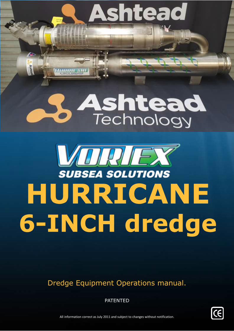
HURRICANE6-INCH dredge
All information correct as July 2011 and subject to changes without notification.
Dredge Equipment Operations manual.
PATENTED
Index
1. Cover page
2. Index
3. Introduction
4. Introduction continued
5. Specifications and performance and removal rates
6. User checklist
7. User checklist continued
8. Hydraulics
9. Hydraulic continued
10. Installation: reversal valve and ROV mounting plate
11. Installation: water connections
12. Installation: hose connections general
13. Shipping box
14. Inventory
15. Spares
16. Axial pump repair procedures
17. Axial pump repair procedures
18. Trouble shooting
19. Contacts
Your safety is your responsibility. Please ask if you are unsure about anything.
Introduction
The Vortex HURRICANE 6-inch is characterized by the following advantages:
• No depth limitations
• Quick mobilization
• Easy operation
The HURRICANE 6-inch dredge Is designed for higher capacity hydraulic supplies that enable a dredge Inlet vacuum up to 15.3 in/hg (52
kpa) at 3000 psi and 80lpm. The Vortex HURRICANE 6-inch is designed for Subsea excavation and disposal of seabed materials up to
150 millimeters in size. It can be mounted to any Work Class ROV and requires no ship deck space and sea fastening. The Vortex
HURRICANE 6-inch is very powerful, has no depth limitations and is quick and easy to mobilize and operate, it can also be run in air.
The Vortex HURRICANE 6-inch equipment can be operated and maintained by the ROV crew.
Vortex has developed a dredge kit with two primary considerations:
First priority is ease of mobilization. The client needs to see rapid deployment of hire gear. The entire kit is shipped in one single box.
Second priority is power. Our HURRICANE 6-inch dredge has shown under real world conditions to provide removal rates well in
excess of other 6-inch dredges. We have included the option of a jetting head kit.
The Vortex HURRICANE 6-inch equipment is easy to set up and use. However, if on site support is agreed in the contract, Vortex
Personnel will assist during mobilization and demobilization and or support the project during the entire operation.
Your safety is your responsibility. Please ask if you are unsure about anything.

Introduction continued
Operating Limits
The operating limit for the Vortex HURRICANE 6-inch , will be the responsibility of the Senior ROV person on-site. The limitation
being the ability to safely deploy and recover the ROV system with the Vortex HURRICANE 6-inch attached. Care must be taken whilst
during launch and recovery operations to prevent damage to all components of the dredge system and the ROV.
Risks - Normal Operations
All personnel involved in deck operations shall be aware of the potential risk described hereafter.
• Crane Handling (possible danger of e.g. heavy falling object)
• Launch and recovery of equipment over the side of the vessel
• Personnel working over open sea (typical personnel working with launch and recovery of equipment from vessel
deck or moon pool)
• Object falling down from height (rocks following the equipment when recovering)
• Working with equipment under pressure (hydraulics or water)
• Hydraulic oil spillage
Safety
Personal protection equipment recommended for use when working on ship/platform deck
• Hard Hat
• Safety glasses
• Gloves
• Safety Boots
• Overall
Vortex TORNADO 4-inch Introduction
The Vortex HURRICANE 6-inch is designed for Subsea excavation and disposal of sediments and gravel up to 150 millimeters. It is easily
mounted to the ROV and requires no ship deck space and sea fastening. The Vortex HURRICANE 6-inch requires no specialist operator
or additional cables between ship and sea floor.
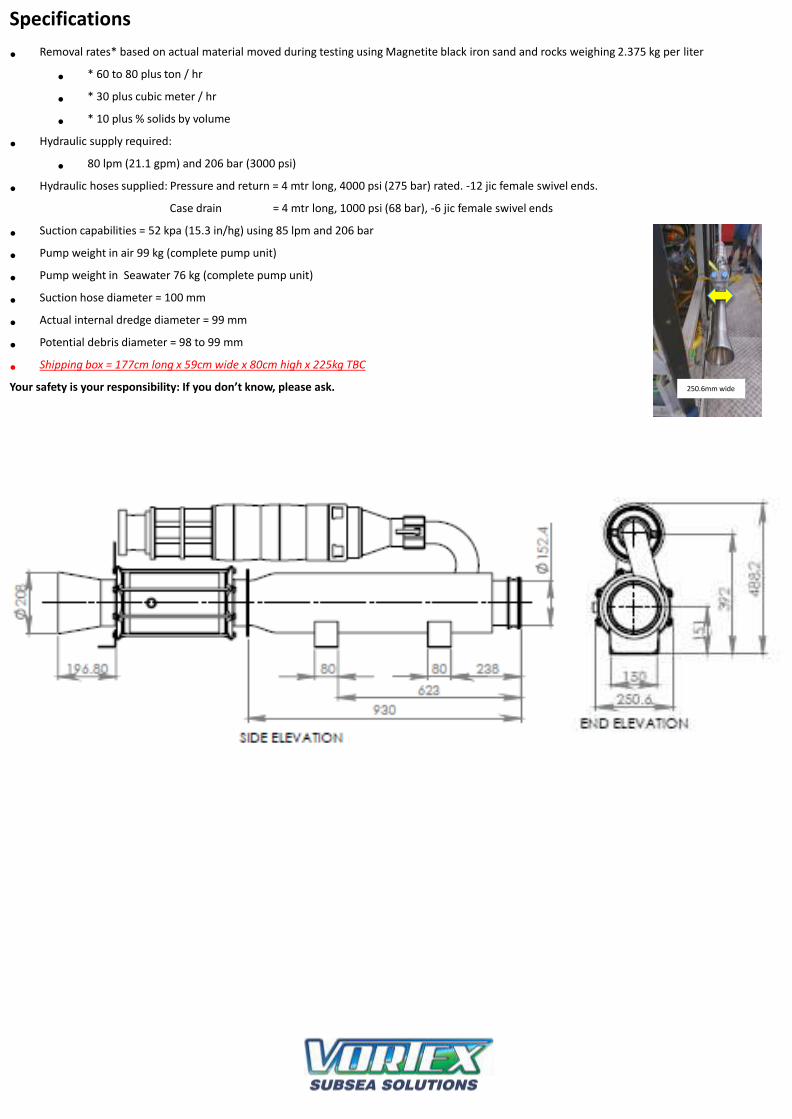
Specifications
• Removal rates* based on actual material moved during testing using Magnetite black iron sand and rocks weighing 2.375 kg per liter
• * 60 to 80 plus ton / hr
• * 30 plus cubic meter / hr
• * 10 plus % solids by volume
• Hydraulic supply required:
• 80 lpm (21.1 gpm) and 206 bar (3000 psi)
• Hydraulic hoses supplied: Pressure and return = 4 mtr long, 4000 psi (275 bar) rated. -12 jic female swivel ends.
Case drain = 4 mtr long, 1000 psi (68 bar), -6 jic female swivel ends
• Suction capabilities = 52 kpa (15.3 in/hg) using 85 lpm and 206 bar
• Pump weight in air 99 kg (complete pump unit)
• Pump weight in Seawater 76 kg (complete pump unit)
• Suction hose diameter = 100 mm
• Actual internal dredge diameter = 99 mm
• Potential debris diameter = 98 to 99 mm
• Shipping box = 177cm long x 59cm wide x 80cm high x 225kg TBC
Your safety is your responsibility: If you don’t know, please ask. 250.6mm wide

User Checklist Before Dive
To prevent any damage to the equipment this checklist must be followed
Project: ............................................................................................... Dredge No: ...................................................
Item Description Checked Comments Date
1. Ensure ROV can and does supply:OPTIMUM FLOW IS 80 lpm (21 gpm) OPTIMUM PRESSURE IS 3000 psi (206 bar) DO NOT RUN PUMP IN AIR: ALWAYS RUN IN WATER
(4500 psi max) Follow hose directions as shown
2. All fittings are checked for leakage
3. All hose clamps are checked
4. Pumps are fastened, no loose screws
5. Suction hose is fastened
6. Dredge is fastened, no loose ends
7. All hoses are fastened and in proper condition
8. Filter for induction is mounted in clean water
9. No hoses are squeezed or bent
10. Inlet nozzle is mounted correctly
11. Case drain and coupling are filled with clean oil
Comments:
.......................................................................................................................................................................................................................
.......................................................................................................................................................................................................................
....................................................................................................................................................................................................... ...
Dredge is checked by: ............................................................................................
Date: ............................................................................................
TORNADO 4-INCH ROV DREDGEEQUIPMENT OPERATIONS MANUAL

User Checklist Before Dive
To prevent any damage to the equipment this checklist must be followed
Project: ............................................................................................... Dredge No: ...................................................
Item Description Checked Comments Date
1. Equipment used in the sea must be DO NOT RUN PUMP IN AIR: ALWAYS RUN IN WATER
properly cleaned with fresh water
2. All fittings are checked for leakage
3. All hose clamps are checked
4. Pumps are fastened, no loose screws
5 Suction hose is fastened
6. Dredge is fastened and in proper condition
7 All hoses are fastened and in proper condition
8. No hoses are squeezed or bent
9. Hydraulic motor and coupling is filled with clean oil
10. Broken parts are reported to vortex
Comments: .................................................................................................................................................................................
...........................................................................................................................................................................................
Dredge is checked by: ............................................................................................
Date: ............................................................................................
What were the positives? ...................................................................................................................................................
What were the negatives? ..................................................................................................................................................
Suggestions to make this kit better for you to use in the field:
............................................................................................................................................................
TORNADO 4-INCH ROV DREDGEEQUIPMENT OPERATIONS MANUAL
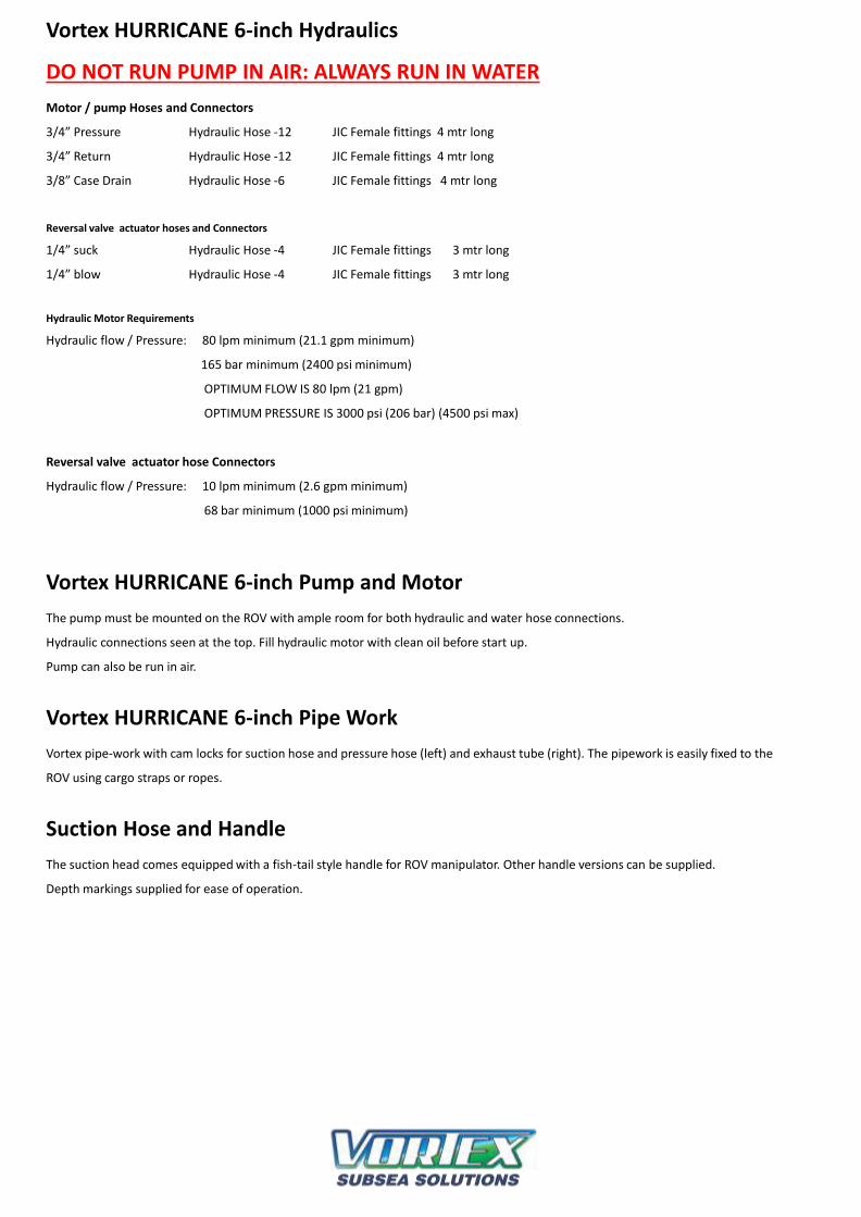
Vortex HURRICANE 6-inch Hydraulics
DO NOT RUN PUMP IN AIR: ALWAYS RUN IN WATER
Motor / pump Hoses and Connectors
3/4” Pressure Hydraulic Hose -12 JIC Female fittings 4 mtr long
3/4” Return Hydraulic Hose -12 JIC Female fittings 4 mtr long
3/8” Case Drain Hydraulic Hose -6 JIC Female fittings 4 mtr long
Reversal valve actuator hoses and Connectors
1/4” suck Hydraulic Hose -4 JIC Female fittings 3 mtr long
1/4” blow Hydraulic Hose -4 JIC Female fittings 3 mtr long
Hydraulic Motor Requirements
Hydraulic flow / Pressure: 80 lpm minimum (21.1 gpm minimum)
165 bar minimum (2400 psi minimum)
OPTIMUM FLOW IS 80 lpm (21 gpm)
OPTIMUM PRESSURE IS 3000 psi (206 bar) (4500 psi max)
Reversal valve actuator hose Connectors
Hydraulic flow / Pressure: 10 lpm minimum (2.6 gpm minimum)
68 bar minimum (1000 psi minimum)
Vortex HURRICANE 6-inch Pump and Motor
The pump must be mounted on the ROV with ample room for both hydraulic and water hose connections.
Hydraulic connections seen at the top. Fill hydraulic motor with clean oil before start up.
Pump can also be run in air.
Vortex HURRICANE 6-inch Pipe Work
Vortex pipe-work with cam locks for suction hose and pressure hose (left) and exhaust tube (right). The pipework is easily fixed to the
ROV using cargo straps or ropes.
Suction Hose and Handle
The suction head comes equipped with a fish-tail style handle for ROV manipulator. Other handle versions can be supplied.
Depth markings supplied for ease of operation.

Vortex HURICANE 6-inch Hydraulics
DO NOT RUN PUMP IN AIR: ALWAYS RUN IN WATER
Hydraulic Schematics
Vortex HURRICANE 6-inch Hydraulic Hoses
• Hydraulic hoses for pump/motor connections.
• Two 4 mtr lengths 3/4’ hoses
• One 3 mtr length 3/8”
Hydraulic hoses 4 mtr long each.4250 psi (293 bar) pressure rating.-12 jic Pressure, -12 jic tank, -6 jic case drain.Ensure ROV can and does supply 75 lpm minimum (19 gpm minimum) 165 bar minimum (2400 psi minimum) before fitting dredge kit.OPTIMUM FLOW IS 80 lpm (21 gpm)OPTIMUM PRESSURE IS 3000 psi (206 bar) (4500 psi max)
TORNADO 4-INCH ROV DREDGEEQUIPMENT OPERATIONS MANUAL
Reversal valve1000 psi and 10lpm minimum to operate
ROV hydraulic valve
Vortex 4 inch hydraulic connections to ROV.
Water jetter ring valve200 psi and 12lpm minimum to operate
ROV hydraulic valve
50mm long, -4 jic female
swivel end hoses.
4mtr long, -4 jic female
swivel end hoses.
Case drain to tank
Pressure and tank return clearly marked.

Installation: Reversal valve connections and ROV mount plate
Reversal valve actuator and hoses.Included in kit:, diverter valve, hydraulic hoses, ¾ water hose goes between water pump and reversal valve..
Connect ¾ inch water hoses to outlet of water pump and water control inlet of reversal valve.Opening actuator diverts water from water pump to reversal valve to actuate urethane bladder which closes / blocks flow in reversal valve and changes dredge direction and go into “blow” mode. Closing actuator allows bladder to revert to relaxed state opening flow path allowing dredge to revert to “suck” mode.
Dredge shown mounted to ROV using supplied aluminum angle. Drill supplied angle to suit.
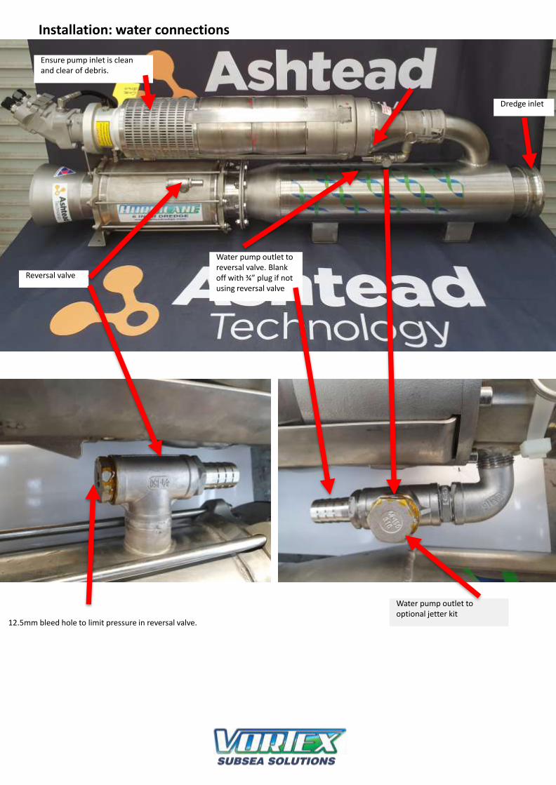
Installation: water connections
Dredge inlet
Ensure pump inlet is clean and clear of debris.
Water pump outlet to reversal valve. Blank off with ¾” plug if not using reversal valve
Water pump outlet to optional jetter kit
Reversal valve
12.5mm bleed hole to limit pressure in reversal valve.
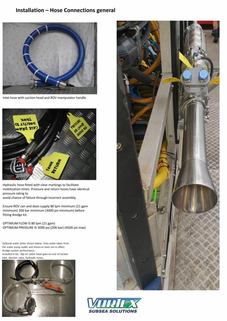
Installation – Hose Connections general
Hydraulic hose fitted with clear markings to facilitate mobilization times. Pressure and return hoses have identical pressure rating toavoid chance of failure through incorrect assembly.
Ensure ROV can and does supply 80 lpm minimum (21 gpmminimum) 206 bar minimum (3000 psi minimum) before fitting dredge kit.
OPTIMUM FLOW IS 80 lpm (21 gpm)OPTIMUM PRESSURE IS 3000 psi (206 bar) (4500 psi max)
Inlet hose with suction head and ROV manipulator handle.
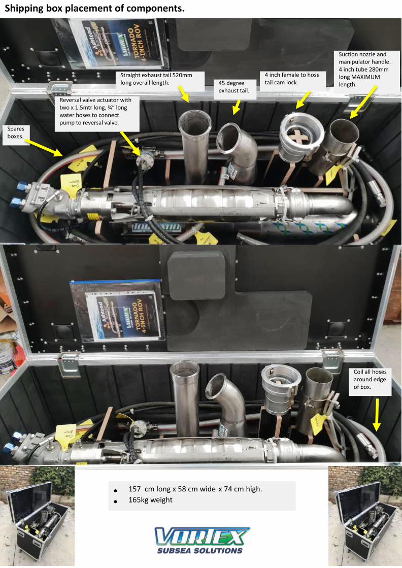
Shipping box placement of components.
Suction nozzle and manipulator handle. 4 inch tube 280mm long MAXIMUM length.
4 inch female to hose tail cam lock.45 degree
exhaust tail.
Straight exhaust tail 520mm long overall length.
Spares boxes.
Reversal valve actuator with two x 1.5mtr long, ¾” long water hoses to connect pump to reversal valve.
Coil all hoses around edge of box.
• 157 cm long x 58 cm wide x 74 cm high.
• 165kg weight
TORNADO 4-INCH ROV DREDGEEQUIPMENT OPERATIONS MANUAL
Inventory
• 4 inch dredge unit with integral reversal valve
• Two x 4mtr long -12 Jic female swivel P and T hoses
• One x 4mtr long -6 jic female swivel case drain hose
• One x water reversal valve actuator with two x 3mtr long -4 jic female swivel hyd hoses
• 10 x 75 x 150mm alloy, dredge to ROV mounting plate
• One x 595mm long 4 inch exhaust tail with 4 to 6 inch flare on the end with triclove clamp
• One x 4 inch, 45 degree elbow with 4 to 6 inch flare on the end with triclove clamp
• One x 4 inch female camlock with 4 inch hose tail. For suction hose
• Ove x 4 inch stainless tube, 300mm long with ROV manip handle. For suction hose
• One x generic spares kit as shown below
• One x water pump spares kit as shown below
1 x Mech. seal rotor # 10185
1 x Mech. seal seat # 10180
• One x operations manual
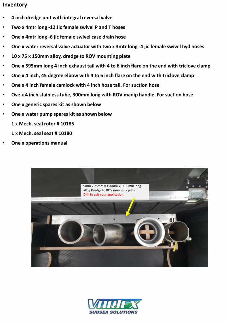
9mm x 75mm x 150mm x 1100mm long alloy Dredge to ROV mounting plate.Drill to suit your application.
TORNADO 4-INCH ROV DREDGEEQUIPMENT OPERATIONS MANUAL
Spare Components
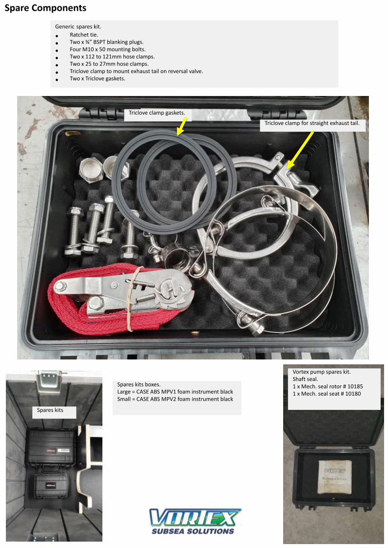
Generic spares kit.
• Ratchet tie.
• Two x ¾” BSPT blanking plugs.
• Four M10 x 50 mounting bolts.
• Two x 112 to 121mm hose clamps.
• Two x 25 to 27mm hose clamps.
• Triclove clamp to mount exhaust tail on reversal valve.
• Two x Triclove gaskets.
Spares kits
Vortex pump spares kit.Shaft seal.1 x Mech. seal rotor # 101851 x Mech. seal seat # 10180
Spares kits boxes. Large = CASE ABS MPV1 foam instrument blackSmall = CASE ABS MPV2 foam instrument black
Triclove clamp for straight exhaust tail.
Triclove clamp gaskets.
Axial pump repair procedures
Mechanical seal replacement:
1. Remove pump suction screen
2. Remove M12 bolts holding aluminium motor adaptor to stainless pump terminal and remove
drive assembly
3. Holding motor in a vise with shaft pointing vertical upwards, unfasten motor capscrews and
remove aluminium adaptor from motor assembly, taking care to avoid contact between seal
stationary seat and shaft surface.
4. Remove circlip and seal seat retainer from motor adaptor. Remove seat and replace with new
item from service kit. Refit retainer in same orientation as when removed and replace circlip.
5. Slide mechanical seal rotor from shaft and fit replacement seal rotor hard back against rear
shoulder of sleeve using light hydraulic oil as a lubricant.
6. Clean both seal face using a lint free cloth and clear gasoline (or equivalent) – lubricate rotor face
with a drop of clean hydraulic oil.
7. Assemble parts in reverse order using torque settings as laid down in torque chart in this
instruction set.
Hydraulic motor replacement:
1. Disassemble unit per steps 1-3 in “Mechanical seal change” instruction
2. Fit plastic protecting sleeve from service kit to shaft spline, holding firmly with vise-grip, and
using a 5mm allen key, remove the shaft retaining capscrew. Using slide hammer with a 12mm
thread remove the shaft from the hydraulic motor.
3. Lubricate the replacement hydraulic motor shaft with a light Moly disulphide paste, refit spacer
and key and slide on the splined stub shaft. If necessary use a hollow drift onto the slide end
shoulder to drive the shaft hard down against the spacer.
4. Clean up the 6mm shaft fastening capscrew and apply a light coating of “BlueMax” or equivalent
silicone sealant to the underside of the head and torque the capscrew to 8 nm.
5. Replace the seal rotor and reassemble the pumpset all per steps 4-6 in the “Mechanical seal
replacement” description.
Torque settings:
M6 – shaft retainer capscrew 8nm
M10 – motor retaining capscrew 12nm
M12 – Adaptor bolts 20nm

Axial pump repair procedures
Air test mechanical seal - 20psi
Apply Blue Max ” or equivalent silicone sealant to underside of cap screw
Apply grease to spline
fit O ring into adaptor recess
fit O-ring - seat -retainer ring and circlip
fit shaft with hollow drift
Push seal onto shaft with silicone grease
Lubricate shaft with light hydraulic oil as a lubricant
Remove shaft - using slide hammer if necessary
Torque sleeve fastening cap screw
Slide joint section to remove screen from pump
fit adaptor to motorfasten motor to adaptor
Fasten pump affixing cap screws
Trouble Shooting
Symptom: Water pump not operating
Remedy:
1. Ensure that the hydraulic hoses are connected as per manual drawings and match connection labels.
2. Check that 80 lpm minimum (21 gpm minimum) 206 bar minimum (3000 psi minimum) can be seen directly at the Vortex
water pump hydraulic motor. OPTIMUM FLOW IS 80 lpm (21 gpm) OPTIMUM PRESSURE IS 3000 psi (206 bar) (4500 psi max).
3. Check any quick connect fittings you may have in the circuit as they can sometimes be faulty.
4. Are your thrusters using most of the available system flow and starving your circuit feeding the Vortex water pump?
5. Ensure the Vortex case drain is connected directly to tank. It is preferable to connect as close as possible to the
reservoir and not run any hoses through quick connects.
Symptom: Debris removal slow
Remedy:
1. Check the caged nozzle of inlet hose is not blocked. Stop hydraulic flow to water pump to allow rocks and
debris to be cleared.
2. Check that all cam locks are fastened and secured correctly.
3. Check all cam lock o-rings are in place and in good condition.
4. Use steady and consistent movements when plunging suction hose inlet into seabed. Try side to side and up and down
movements of suction hose inlet. Differing conditions may require changing methods.
5. Check all hydraulic remedies as seen in “water pump not operating” section of trouble shooting.
6. Check inlet and exhaust hoses are not bent or blocked.
Joe Goodin - Managing Director
VORTEX International Ltd, 27 Parrs Road, RD1, New Plymouth, New Zealand
Tel/Fax: +64 (6) 753 8102, Mobile: + 64 (0) 27 688 5372, Email: [email protected], www.vortexdredge.com
In association with Ashtead Technology:
ABERDEENAshtead Technology LtdAshtead House, Discovery Drive, ArnhallBusiness Park, Westhill, Aberdeenshire AB32 6FGTel: +44 (0)1224 771888, Email: [email protected]
SINGAPOREAshtead Technology (S.E.A) Pte LtdLoyang Offshore Supply Base, 25 Loyang Crescent, Block 302, Unit 02-12 TOPS Ave 3, PO Box 5157, SINGAPORE 508988
Tel: +65 6545 9350,Email: [email protected]
HOUSTONAshtead Technology Offshore Inc19407 Park Row, Suite 170, Houston, TX 77084, U.S.ATel: +1 281 398 9533,Email: [email protected]
SCOPE ENGINEERING (Ashtead Technology Agent)
Scope Engineering (WA) Pty Ltd35 Stuart Drive, Henderson, Western Australia 6166T: +61 8 6498 9642 F: +61 8 6498 9584,Email: [email protected]
Innova ASP.O. Box 390 Forus, 4067 StavangerPhone: +47 51 96 17 00Fax: +47 51 96 17 01E-mail: [email protected]
TES Survey Equipment Services LLCPO Box 128256Abu DhabiUAETel: + 971 2 650 7710Fax: +971 2 650 7200E-mail: [email protected]