hustler sport general service manual - datatailmedia.datatail.com/docs/manual/163555_en.pdf ·...
TRANSCRIPT
Hustler® SportGeneral Service Manual
•••••200 South Ridge Road •••Hesston, Kansas •67062-2097
108934 REV E

The Engine Owner’s Manual provides information regarding the U.S. Environmental Protection Agency (EPA)and the California Emission Control Regulation of emission systems, maintenance and warranty.
Keep Engine Owner’s Manual with your unit. Should the Engine Owner’s Manual become damaged orillegible, replace immediately. Replacements may be ordered per the information found in the ProductInformation section of the owner’s manual.
Federal law and California State law prohibit the following acts or the causing thereof:1. The removal or rendering inoperative by any person other than for purposes of maintenance,
repair, replacement, of any device or element of design incorporated into any equipment for thepurposes of emissions control prior to or after its sales or delivery to the ultimate purchaser orwhile it is in use, or
2. The use of the equipment after such device or element of design has been removed or renderedinoperative by any person.
WARNINGWARNINGWARNING
The engine exhaust from this product contains chemicals known to the state
of California to cause cancer, birth defects or other reproductive harm.
NOTICE OF REQUIREMENT OF SPARK ARRESTER MUFFLER
This equipment may create sparks that can start fires around dry vegetation. California Public Resources CodeSection 4442.6 provides that it is unlawful to use or operate an internal combustion engine on any forest-covered,brush-covered, or grass-covered land unless the engine is equipped with a spark arrester maintained in effectiveworking order. A spark arrester is a device constructed of nonflammable materials specifically for the purpose ofremoving and retaining carbon and other flammable particles over 0.0232 of an inch in size from the exhaust flow ofan internal combustion engine that uses hydrocarbon fuels or which is qualified and rated by the United StatesForest Service. Other states or federal areas may have similar laws. The Operator Should Contact Local FireAgencies For Laws or Regulations Relating to Fire Prevention Requirements. THIS EQUIPMENT DOES NOT HAVEA SPARK ARRESTER AND YOU SHOULD CONTACT YOUR AUTHORIZED DEALER FOR THE PURCHASE OFA SPARK ARRESTER.
Inspect spark arrester daily; replace every 500 hours or as needed.
REV E 108934
Table of Contents
General Information . . . . . . . . . . . . . . . . . . . . . . . . . . . . . . . . . . . . . 1-1
Hustler® Service Program . . . . . . . . . . . . . . . . . . . . . . . . . . . . . 1-1
Maintenance Introduction . . . . . . . . . . . . . . . . . . . . . . . . . . . . . . 1-1
Warranty. . . . . . . . . . . . . . . . . . . . . . . . . . . . . . . . . . . . . . . . . . . 1-1
Safety. . . . . . . . . . . . . . . . . . . . . . . . . . . . . . . . . . . . . . . . . . . . . . . . 2-1
Safe Servicing Practices . . . . . . . . . . . . . . . . . . . . . . . . . . . . . . 2-1
Pre-Operation Precautions. . . . . . . . . . . . . . . . . . . . . . . . . . . . . 2-1
Operation Precautions . . . . . . . . . . . . . . . . . . . . . . . . . . . . . . . . 2-2
Operate Machine Safely. . . . . . . . . . . . . . . . . . . . . . . . . . . . . . . 2-2
General Maintenance Precautions . . . . . . . . . . . . . . . . . . . . . . . 2-2
Maintenance Precautions. . . . . . . . . . . . . . . . . . . . . . . . . . . . . . 2-2
Torque . . . . . . . . . . . . . . . . . . . . . . . . . . . . . . . . . . . . . . . . . . . . . . . 3-1
Standard Torques. . . . . . . . . . . . . . . . . . . . . . . . . . . . . . . . . . . . 3-1
Special Torques . . . . . . . . . . . . . . . . . . . . . . . . . . . . . . . . . . . . . 3-1
Power Unit Maintenance . . . . . . . . . . . . . . . . . . . . . . . . . . . . . . . . . 4-1
Steering Adjustments . . . . . . . . . . . . . . . . . . . . . . . . . . . . . . . . . 4-1
Park Brake Spring Adjustment . . . . . . . . . . . . . . . . . . . . . . . . . . 4-3
Belts . . . . . . . . . . . . . . . . . . . . . . . . . . . . . . . . . . . . . . . . . . . . . . 4-4
Hydraulic Pump Belt Adjustment . . . . . . . . . . . . . . . . . . . . . . . . 4-4
Tires . . . . . . . . . . . . . . . . . . . . . . . . . . . . . . . . . . . . . . . . . . . . . . 4-4
Engine Maintenance . . . . . . . . . . . . . . . . . . . . . . . . . . . . . . . . . . . . 5-1
General Engine Maintenance. . . . . . . . . . . . . . . . . . . . . . . . . . . 5-1
Engine Oil and Filter. . . . . . . . . . . . . . . . . . . . . . . . . . . . . . . . . . 5-1
Engine Air Filter . . . . . . . . . . . . . . . . . . . . . . . . . . . . . . . . . . . . . 5-1
Carbon Canister . . . . . . . . . . . . . . . . . . . . . . . . . . . . . . . . . . . . . 5-2
Fuel Evaporation System Filter . . . . . . . . . . . . . . . . . . . . . . . . . 5-2
Fuel & Evaporative System Line Routings . . . . . . . . . . . . . . . . . 5-2
Engine RPM Settings . . . . . . . . . . . . . . . . . . . . . . . . . . . . . . . . . 5-3
Deck Adjustments . . . . . . . . . . . . . . . . . . . . . . . . . . . . . . . . . . . . . . 6-1
Deck Leveling. . . . . . . . . . . . . . . . . . . . . . . . . . . . . . . . . . . . . . . 6-1
Blades . . . . . . . . . . . . . . . . . . . . . . . . . . . . . . . . . . . . . . . . . . . . 6-3
Belts . . . . . . . . . . . . . . . . . . . . . . . . . . . . . . . . . . . . . . . . . . . . . . 6-4
Deck Belt Adjustment . . . . . . . . . . . . . . . . . . . . . . . . . . . . . . . . . 6-4
42" Deck Belt Routing & Tensioning . . . . . . . . . . . . . . . . . . . 6-5
48" Deck Belt Routing & Tensioning . . . . . . . . . . . . . . . . . . . . 6-5
54" Deck Belt Routing & Tensioning . . . . . . . . . . . . . . . . . . . . 6-6
36" RD Deck Belt Routing & Tensioning . . . . . . . . . . . . . . . . . 6-7
108934 toc-1 REV E

Electrical . . . . . . . . . . . . . . . . . . . . . . . . . . . . . . . . . . . . . . . . . . . . . .7-1
Electrical Schematic — Briggs & Stratton & Kawasaki . . . . . . . .7-1
Electrical Schematic — Honda GXV 530 . . . . . . . . . . . . . . . . . .7-2
Electrical Schematic — Kohler . . . . . . . . . . . . . . . . . . . . . . . . . .7-3
Maintenance . . . . . . . . . . . . . . . . . . . . . . . . . . . . . . . . . . . . . . . . . . .8-1
Maintenance Locator Chart . . . . . . . . . . . . . . . . . . . . . . . . . . .8-2
Troubleshooting . . . . . . . . . . . . . . . . . . . . . . . . . . . . . . . . . . . . . . . .9-1
REV E toc-2 108934

GENERAL INFORMATION
Hustler® Service Program
This manual is part of a service package for the Hustler® Sportmowers. Use of this manual in conjunction with other Hustler®
mower and component manuals will provide the informationnecessary to service and maintain Hustler® Sport mowers.
This General Service Manual is a service guide for use byService Technicians. It provides the necessary informationneeded to perform normal maintenance requirements on theseunits.
The Parts Manual provides a complete parts listing for theunit. Use this manual when ordering parts.
The Operator's Manual provides fundamental operationalinformation and operational safety that is needed when operat-ing the mower.
The component manuals are furnished by the various manu-facturers to be used for the troubleshooting and servicing oftheir products.
Maintenance Introduction
Regular maintenance is the best prevention for costly down-time or expensive, premature repair. The following pages con-tain suggested maintenance information and schedules whichthe operator/mechanic should follow on a routine basis.
Remain alert for unusual noises, they could be signaling aproblem. Visually inspect the machine for any abnormal wear ordamage. A good time to detect potential problems is while per-forming scheduled maintenance service. Correcting the problemas quickly as possible is the best insurance.
Clear away heavy build-up of grease, oil and dirt, especiallyin the engine and under the seat platform areas; minute dust par-
ticles are abrasive to close-tolerance engine and hydraulicassemblies.
Daily inspect mower for grass clippings and wire and stringtangles. The underside of the mower deck will collect a build-upof grass clippings and dirt, especially when grass is wet or hashigh moisture content. This build-up will harden, restrictingblade and air movement and will probably show a poorer qualityof cutting. Therefore it should be removed routinely.
To do this it will be necessary to raise and block the deck,using jack stands or blocks, in the full up position and scrape thebuild-up from underneath.
Some repairs require the assistance of a trained servicemechanic and should not be attempted by unskilled personnel.Consult your Hustler® Turf Equipment service center whenassistance is needed.
Information included in this manual was current at the time ofprinting, but subsequent production changes may cause yourmachine to vary slightly in detail. Hustler® Turf Equipmentreserves the right to redesign and change the machine as deemednecessary, without notification. If a change has been made toyour machine which is not reflected in this service manual con-tact the Customer Service Department at Hustler® Turf Equip-ment for additional information.
Warranty
Warranty repair must be performed by a Hustler® Turf Equip-ment Authorized Dealer before warranty credit can be allowed.Work performed by anyone other than an Authorized Dealerwill invalidate the warranty claim and warranty credit will notbe approved.
108934 1-1 REV E

REV E 1-2 108934
SAFETY
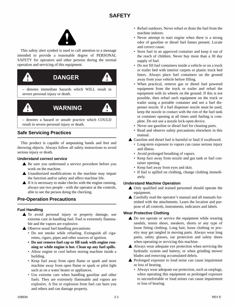
This safety alert symbol is used to call attention to a messageintended to provide a reasonable degree of PERSONALSAFETY for operators and other persons during the normaloperation and servicing of this equipment.
Safe Servicing Practices
This product is capable of amputating hands and feet andthrowing objects. Always follow all safety instructions to avoidserious injury or death.
Understand correct service Be sure you understand a service procedure before you
work on the machine. Unauthorized modifications to the machine may impair
the function and/or safety and affect machine life. If it is necessary to make checks with the engine running,
always use two people - with the operator at the controls,able to see the person doing the checking.
Pre-Operation Precautions
Fuel Handling To avoid personal injury or property damage, use
extreme care in handling fuel. Fuel is extremely flamma-ble and the vapors are explosive.
Observe usual fuel handling precautions:• Do not smoke while refueling. Extinguish all ciga-
rettes, cigars, pipes and other sources of ignition.• Do not remove fuel cap or fill tank with engine run-
ning or while engine is hot. Clean up any fuel spills.• Allow engine to cool before storing machine inside a
building.• Keep fuel away from open flame or spark and store
machine away from open flame or spark or pilot lightsuch as on a water heater or appliances.
• Use extreme care when handling gasoline and otherfuels. They are extremely flammable and vapors areexplosive. A fire or explosion from fuel can burn youand others and can damage property.
• Refuel outdoors. Never refuel or drain the fuel from themachine indoors.
• Never attempt to start engine when there is a strongodor of gasoline or diesel fuel fumes present. Locateand correct cause.
• Store fuel in an approved container and keep it out ofthe reach of children. Never buy more than a 30 daysupply of fuel.
• Do not fill fuel containers inside a vehicle or on a truckor trailer bed with interior carpets or plastic truck bedliners. Always place fuel containers on the groundaway from your vehicle before filling.
• When practical, remove gas or diesel fuel poweredequipment from the truck or trailer and refuel theequipment with its wheels on the ground. If this is notpossible, then refuel such equipment on the truck ortrailer using a portable container and not a fuel dis-penser nozzle. If a fuel dispenser nozzle must be used,keep the nozzle in contact with the rim of the fuel tankor container opening at all times until fueling is com-plete. Do not use a nozzle lock-open device.
• Never use gasoline or diesel fuel for cleaning parts.• Read and observe safety precautions elsewhere in this
manual. Gasoline and diesel fuel is harmful or fatal if swallowed.
• Long-term exposure to vapors can cause serious injuryand illness.
• Avoid prolonged breathing of vapors.• Keep face away from nozzle and gas tank or fuel con-
tainer opening.• Keep fuel away from eyes and skin.• If fuel is spilled on clothing, change clothing immedi-
ately.
Understand Machine Operation Only qualified and trained personnel should operate the
equipment. Carefully read the operator’s manual and all manuals fur-
nished with the attachments. Learn the location and pur-pose of all controls, instruments, indicators and labels.
Wear Protective Clothing Do not operate or service the equipment while wearing
sandals, tennis shoes, sneakers, shorts or any type ofloose fitting clothing. Long hair, loose clothing or jew-elry may get tangled in moving parts. Always wear longpants, safety glasses, ear protection and safety shoeswhen operating or servicing this machine.
Always wear adequate eye protection when servicing thehydraulic system and battery, or when grinding mowerblades and removing accumulated debris.
Prolonged exposure to loud noise can cause impairmentor loss of hearing.• Always wear adequate ear protection, such as earplugs,
when operating this equipment as prolonged exposureto uncomfortable or loud noises can cause impairmentor loss of hearing.
DANGER
– denotes immediate hazards which WILL result insevere personal injury or death.
WARNING
– denotes a hazard or unsafe practice which COULDresult in severe personal injury or death.
108934 2-1 REV E

• Do not wear radios or music headphones while operat-ing the machinery. Safe operation requires your fullattention.
Operation Precautions
Avoid Fire Hazards Clean flammable material from machine. Prevent
fires by keeping engine compartment, top of deck,exhaust area, battery, hydraulic lines, fuel line, fueltank and operator’s station clean of accumulatedtrash, grass clippings, and other debris. Always cleanup spilled fuel and oil.
Start Engine Safely Avoid possible injury or death from machine runaway. Do not start engine by shorting across starter terminals. Before you start the engine:
• Sit on the operator’s seat.• Move control levers to the neutral/brake position.
Operate Machine Safely
Refer to the unit’s operator’s manual for complete safetyinformation on safe machine operation.
Always maintain a safe distance from people and petswhen mowing
Always be aware of what is behind the machine beforebacking up.
Never leave machine unattended with ignition key inswitch, especially with children present.
Follow daily and weekly checklists, making sure hosesare tightly secured and bolts are tightened.
Always keep engine and machine clean, removing accu-mulated dirt, trash and other material from machine.
Never put hands or feet under any part of the machinewhile it is running.
Never attempt to start engine when there is a strong odorof gasoline fumes present. Locate and correct cause.
Keep all safety shields and covers in place, except forservicing.
Do not touch hot parts of machine.
General Maintenance Precautions
Repairs or maintenance requiring engine powershould be performed by trained maintenance person-nel only.
Never run the engine in an enclosed area unless exhaustis vented to the outside. Exhaust gases contain carbonmonoxide which is an odorless and deadly poison.
Unless specifically required, DO NOT have engine run-ning when servicing or making adjustments to mower.Park the machine on level ground. Place steering controllevers in the park brake position, disengage deck clutch,lower deck, remove ignition switch key and disconnectnegative battery cable before doing any maintenance.Wait for all movement to stop before adjusting, cleaningor repairing. To prevent carbon monoxide poisoning, besure proper ventilation is available when engine must beoperated in an enclosed area.
Before working on or under the deck, make certainengine cannot be accidentally started. Shut engine off,remove ignition switch key and disconnect negative bat-tery cable for maximum safety.
Except when changing or checking belt, always keep beltcovers on mower deck for safety as well as cleanliness.
Use a stick or similar instrument to clean under themower making sure that no part of the body, especiallyarms and hands are under mower.
Keep your machine clean and remove any deposits oftrash and clippings, which can cause engine fires andhydraulic overheating as well as excessive belt wear.Clean up oil or fuel spillage. Allow machine to coolbefore storing.
Always wear adequate eye protection when servicing thehydraulic system and battery, or when grinding mowerblades and removing accumulated debris.
Never attempt to make any adjustments or repairs to themower drive system, mower deck or any attachmentwhile the engine is running or deck clutch is engaged.
Never work under the machine or attachment unless it issafely supported with jack stands. Make certain machineis secure when it is raised and placed on the jack stands.The jack stands should not allow the machine to movewhen the engine is running and the drive wheels arerotating. Use only certified jack stands. Use only appro-priate jack stands, with a minimum weight rating of 2000pounds to block the unit up. Use in pairs only. Follow theinstructions supplied with the vehicle stands.
Keep nuts and bolts tight, especially the blade attachmentbolts. Keep equipment in good working condition.
Never tamper with safety devices. Check their properoperation regularly.
Exercise caution when working under the deck as themower blades are extremely sharp. Wrap the blade(s) orwear gloves and use extra caution when servicing them.
Use only genuine Hustler® replacement parts to ensurethat original standards are maintained.
Maintenance Precautions
Avoid Fire Hazards Be prepared if an accident or fire should occur. Know
where the first aid kit and the fire extinguishers arelocated and how to use them.
Provide adequate ventilation when charging batteries. Do not smoke near battery. Never check fuel level with an open flame. Never use an open flame to look for leaks anywhere on
the equipment. Never use an open flame as light anywhere on or around
the equipment. When preparing engine for storage, remember that fuel
stabilizer is volatile and therefore dangerous. Seal andtape openings after adding the inhibitor. Keep containertightly closed when not in use.
Inspect electrical wiring for worn or frayed insulation.Install new wiring if wires are damaged.
REV E 2-2 108934
Prepare For Emergencies Be prepared if a fire starts. Keep a first aid kit and fire extinguishers available. Keep emergency numbers for doctor, ambulance service,
hospital, and fire department near the telephone.
Prevent Battery Explosions Battery posts, terminals, and related accessories contain
lead and lead compounds, chemicals known to the Stateof California to cause cancer and reproductive harm.Wash hands after handling.
Charge batteries in an open well-ventilated area, awayfrom sparks and flames. Unplug charger before connect-ing or disconnecting from battery. Wear protective cloth-ing and use insulated tools.
Avoid skin and clothing contact with battery acid.• Always wear eye protection when checking the battery,
acid can cause serious injury to skin and eyes. If con-tact occurs, flush area with clean water and call physi-cian immediately. Acid will also damage clothing.
• Do not drink the battery electrolyte.• Do not allow open flame near the battery when charg-
ing.• Hydrogen gas forms inside the battery. This gas is both
toxic and flammable and may cause an explosion ifexposed to flame. Always disconnect the negative(black) battery cable(s) before disconnecting the posi-tive (red) cable(s). Always connect the positive (red)battery cable(s) before connecting the negative (black)cable(s).
• Do not overfill battery.• Electrolyte may overflow and damage paint, wiring or
structure. When cleaning the battery, use soap andwater. Be careful not to get soap and water into the bat-tery. Clean the battery terminals with a solution of fourparts water and one part baking soda when theybecome corroded.
Shorts caused by battery terminals or metal tools touch-ing metal mower components can cause sparks. Sparkscan cause a battery gas explosion which will result in per-sonal injury.• Prevent the battery terminals from touching any metal
mower parts when removing or installing the battery.• Do not allow metal tools to short between the battery
terminals and metal mower parts. Incorrect battery cable routing could cause damage to the
mower and battery cables. This can cause sparks whichcan cause a battery gas explosion which will result in per-sonal injury. Always disconnect the negative (black) bat-tery cable(s) before disconnecting the positive (red)cable(s). Always connect the positive (red) batterycable(s) before connecting the negative (black) cable(s).
Avoid Acid Burns Sulfuric acid in battery electrolyte is poisonous. It is
strong enough to burn skin, eat holes in clothing andcause blindness if splashed in eyes.Avoid the hazard by:• Filling batteries in a well-ventilated area.• Wearing eye protection and rubber gloves.• Avoiding breathing fumes when electrolyte is added.• Avoiding spilling or dripped electrolyte.If you spill acid on yourself:• Flush your skin with water.• Apply baking soda or lime to help neutralize the acid.• Flush your eyes with water for 10-15 minutes. Get
medical attention immediately.If acid is swallowed:• Drink large amounts of water or milk.• Then drink milk of magnesia, beaten eggs or vegetable
oil.• Get medical attention immediately.
108934 2-3 REV E

REV E 2-4 108934
TORQUE
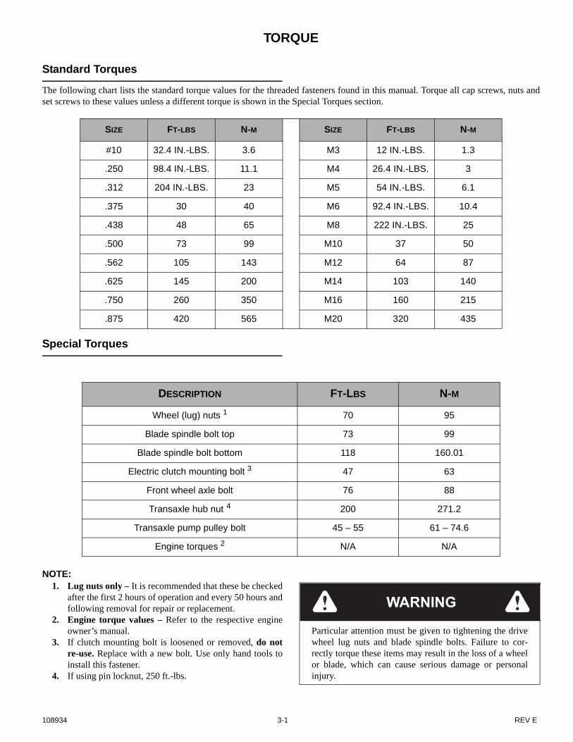
Standard Torques
The following chart lists the standard torque values for the threaded fasteners found in this manual. Torque all cap screws, nuts andset screws to these values unless a different torque is shown in the Special Torques section.
Special Torques
NOTE: 1. Lug nuts only – It is recommended that these be checked
after the first 2 hours of operation and every 50 hours andfollowing removal for repair or replacement.
2. Engine torque values – Refer to the respective engineowner’s manual.
3. If clutch mounting bolt is loosened or removed, do notre-use. Replace with a new bolt. Use only hand tools toinstall this fastener.
4. If using pin locknut, 250 ft.-lbs.
SIZE FT-LBS N-M SIZE FT-LBS N-M
#10 32.4 IN.-LBS. 3.6 M3 12 IN.-LBS. 1.3
.250 98.4 IN.-LBS. 11.1 M4 26.4 IN.-LBS. 3
.312 204 IN.-LBS. 23 M5 54 IN.-LBS. 6.1
.375 30 40 M6 92.4 IN.-LBS. 10.4
.438 48 65 M8 222 IN.-LBS. 25
.500 73 99 M10 37 50
.562 105 143 M12 64 87
.625 145 200 M14 103 140
.750 260 350 M16 160 215
.875 420 565 M20 320 435
DESCRIPTION FT-LBS N-M
Wheel (lug) nuts 1 70 95
Blade spindle bolt top 73 99
Blade spindle bolt bottom 118 160.01
Electric clutch mounting bolt 3 47 63
Front wheel axle bolt 76 88
Transaxle hub nut 4 200 271.2
Transaxle pump pulley bolt 45 – 55 61 – 74.6
Engine torques 2 N/A N/A
WARNING
Particular attention must be given to tightening the drivewheel lug nuts and blade spindle bolts. Failure to cor-rectly torque these items may result in the loss of a wheelor blade, which can cause serious damage or personalinjury.
108934 3-1 REV E

REV E 3-2 108934

POWER UNIT MAINTENANCE
Steering Adjustments
Steering control lever neutral adjustment The mower’s steering has been factory adjusted to eliminate
creeping when the steering control levers are in the neutral posi-tion. However, should the mower begin to creep, the steeringcontrol lever linkage can be adjusted.
Before considering any adjustment, check the tire air pressure.Unequal tire pressure will cause the mower to drift to one side.Refer to tire pressure information in the Tire section for detailedinformation.
NOTE: Proper park brake adjustment must be completedbefore the steering control lever neutral adjustment can be done.Refer to the Park Brake Spring Adjustment section for detailedinformation.
Fine adjustment to the unit’s steering is made with the trans-mission’s control rod.
Neutral is properly adjusted when the steering control leversare in the park brake position and the transmissions do not“whine”.
If this occurs, the steering control linkage may be adjusted asfollows:
1. Raise the rear of the mower and block with certified jackstands. The rear wheels need to be able to rotate freelyand clear of all obstructions.
2. Chock the front tires.
3. Raise the seat platform and disconnect the mower harnessfrom the seat switch. Bypass the seat switch byconnecting the two mower harness female spadestogether. Figure 4-1
4. Loosen the jam nuts on each end of the steering controlrod assemblies. Figure 4-5
5. Set both steering control levers in the park brake position.Figure 4-2NOTE: Both steering control levers need to be in thepark brake position when starting the engine but need tobe moved rapidly out of the park brake position onceengine is started so that the brakes do not fight thetransmissions since they have not yet been adjusted.
6. Loosen the nuts on the rear steering damper ball studs.The dampers must be allowed to slide in the slots in themower frame. Figure 4-5
7. Start the engine. Move the steering control lever to barely
WARNING
This procedure will require that the unit to be raised andblocked up off of the ground. It is necessary for thewheels to rotate without coming in contact with the flooror any object that would permit the unit to propel itself.Stay clear and exercise caution when rotating wheels toprevent injury. Use only appropriate vehicle stands, witha minimum weight rating of 2000 pounds to block theunit up. Use in pairs only. Follow the instructions sup-plied with the vehicle stands.
WARNING
Keep hands, hair, clothing, etc., clear of the cooling fanson top of the transmissions. Exercise extreme caution.
WARNING
Untrained maintenance personnel should never attempt tomake any adjustments or repairs to the mower’s drivesystem while the engine is running. The following proce-dures should be performed by trained maintenancepersonnel only.
Figure 4-1
Figure 4-2
Mower harness
Seat switchFemale
spades
Steering control levers in park brake position
108934 4-1 REV E
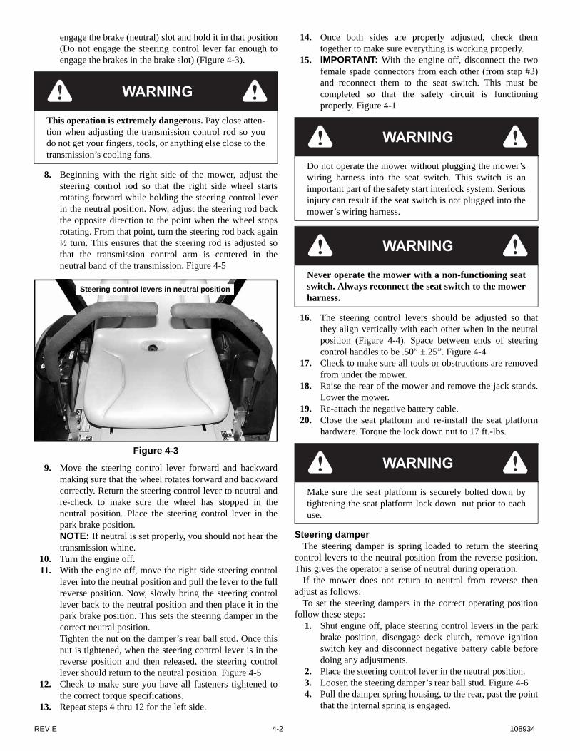
engage the brake (neutral) slot and hold it in that position(Do not engage the steering control lever far enough toengage the brakes in the brake slot) (Figure 4-3).
8. Beginning with the right side of the mower, adjust thesteering control rod so that the right side wheel startsrotating forward while holding the steering control leverin the neutral position. Now, adjust the steering rod backthe opposite direction to the point when the wheel stopsrotating. From that point, turn the steering rod back again½ turn. This ensures that the steering rod is adjusted sothat the transmission control arm is centered in theneutral band of the transmission. Figure 4-5
9. Move the steering control lever forward and backwardmaking sure that the wheel rotates forward and backwardcorrectly. Return the steering control lever to neutral andre-check to make sure the wheel has stopped in theneutral position. Place the steering control lever in thepark brake position. NOTE: If neutral is set properly, you should not hear thetransmission whine.
10. Turn the engine off.11. With the engine off, move the right side steering control
lever into the neutral position and pull the lever to the fullreverse position. Now, slowly bring the steering controllever back to the neutral position and then place it in thepark brake position. This sets the steering damper in thecorrect neutral position. Tighten the nut on the damper’s rear ball stud. Once thisnut is tightened, when the steering control lever is in thereverse position and then released, the steering controllever should return to the neutral position. Figure 4-5
12. Check to make sure you have all fasteners tightened tothe correct torque specifications.
13. Repeat steps 4 thru 12 for the left side.
14. Once both sides are properly adjusted, check themtogether to make sure everything is working properly.
15. IMPORTANT: With the engine off, disconnect the twofemale spade connectors from each other (from step #3)and reconnect them to the seat switch. This must becompleted so that the safety circuit is functioningproperly. Figure 4-1
16. The steering control levers should be adjusted so thatthey align vertically with each other when in the neutralposition (Figure 4-4). Space between ends of steeringcontrol handles to be .50” ±.25”. Figure 4-4
17. Check to make sure all tools or obstructions are removedfrom under the mower.
18. Raise the rear of the mower and remove the jack stands.Lower the mower.
19. Re-attach the negative battery cable.20. Close the seat platform and re-install the seat platform
hardware. Torque the lock down nut to 17 ft.-lbs.
Steering damperThe steering damper is spring loaded to return the steering
control levers to the neutral position from the reverse position.This gives the operator a sense of neutral during operation.
If the mower does not return to neutral from reverse thenadjust as follows:
To set the steering dampers in the correct operating positionfollow these steps:
1. Shut engine off, place steering control levers in the parkbrake position, disengage deck clutch, remove ignitionswitch key and disconnect negative battery cable beforedoing any adjustments.
2. Place the steering control lever in the neutral position.3. Loosen the steering damper’s rear ball stud. Figure 4-64. Pull the damper spring housing, to the rear, past the point
that the internal spring is engaged.
WARNING
This operation is extremely dangerous. Pay close atten-tion when adjusting the transmission control rod so youdo not get your fingers, tools, or anything else close to thetransmission’s cooling fans.
Figure 4-3
Steering control levers in neutral position
WARNING
Do not operate the mower without plugging the mower’swiring harness into the seat switch. This switch is animportant part of the safety start interlock system. Seriousinjury can result if the seat switch is not plugged into themower’s wiring harness.
WARNING
Never operate the mower with a non-functioning seatswitch. Always reconnect the seat switch to the mowerharness.
WARNING
Make sure the seat platform is securely bolted down bytightening the seat platform lock down nut prior to eachuse.
REV E 4-2 108934

5. Release the damper spring housing and allow the internalspring to bring the housing back to the neutral position.
6. Tighten the nut on the steering damper’s rear ball stud.7. Reconnect the negative battery cable.8. To check, move the steering control lever to the reverse
position and release. The steering control lever shouldreturn to the neutral position. If not, repeat steps 1through 7.
Park Brake Spring Adjustment
Occasionally check the park brake spring adjustment using
the following method:1. Shut engine off, place steering control levers in the park
brake position, disengage deck clutch, remove ignitionswitch key and disconnect negative battery cable beforedoing any adjustments.
2. On one side measure the park brake spring. It should becompressed to 1.00”. If it is not, adjust the nylock nutuntil the proper spring compression is achieved (Figure4-7).
3. Repeat for other side.4. Reconnect the negative battery cable.5. Close seat platform and re-install seat platform hardware.
Figure 4-4
Align handles ± .125”
Figure 4-5
Steering damper
Steering damper
stud
Nut
Slot
Jam nut
Jam nut
Steering control
rod
Steering control lever
108934 4-3 REV E

.
Belts
Inspect belts frequently for wear and serviceability. Replace abelt that shows signs of severe cuts, tears, separation, weatherchecking and cracking, or burns caused by slipping. Slight rav-eling of belt covering does not indicate failure, trim ravelingswith a sharp knife.
Inspect the belt pulley grooves and flanges for wear. A newbelt, or one in good condition, should never run against the bot-tom of the groove. Replace the pulley when this is the case, oth-erwise, the belt will lose power and slip excessively.
Never pry a belt to get it on a pulley as this will cut or damagethe fibers of the belt covering.
Keep oil and grease away from belts, and never use belt dress-ings. Any of these will destroy the belt composition in a veryshort time.
Hydraulic Pump Belt Adjustment
The transmission drive belt tension remains constant bymeans of a tension idler and spring. There is no tension adjust-ment of this belt. Figure 4-8
NOTE: Inspect the belt every 100 hours and replace asneeded. Replace the belt every 200 hours or every two (2) yearswhichever comes first.
Tires
It is important for level mowing that the tires have the sameamount of air pressure. The recommended pressures are:
Drive wheels . . . . . . . . . . . . . . . . . . . . . 8-12 psi (55-83 KPa)Front wheels . . . . . . . . . . . . . . . . . . . . . 8-12 psi (55-83 KPa)
If you wish to use non-pneumatic tires on your Hustler®
mower the tires must be an approved tire purchased from Hus-tler® Turf Equipment. Warranty claims will be denied on anymower equipped with unapproved non-pneumatic tires.
Figure 4-6
Figure 4-7
Steering damper
Rear damper ball stud
Nylock nut
Nylock nutBrake arm spring
0.25”
1.00”
WARNING
If the transmission belt fails, loss of control will occurespecially when operating on a slope. If you lose steeringcontrol while operating the machine, place the steeringcontrol levers in the park brake position immediately.Inspect the machine and involve your dealer to resolvethe problem.
Figure 4-8
Top View Hydraulic pump belt
Tension idler
Spring
REV E 4-4 108934

ENGINE MAINTENANCE
General Engine Maintenance
Detailed instructions and recommendations for break-in andregular maintenance are specified in the Engine Owner’s man-ual. Please refer to this manual for engine servicing, lubricatingoil levels with quality and viscosity recommendations, bolttorques, etc. The engine warranty is backed by the manufacturer.
Engine Oil and Filter
Check engine oil daily and after every 4 hours of operation.Mower must be on a level surface when checking oil. Refer toengine manual and maintenance schedule for oil recommenda-tion and capacities.
Change the engine oil and filter after the first 5 hours of oper-ation and then per the engine manufacturer’s recommendationsafter that. If mower is being operated in extremely dirty condi-tions, then it is recommended oil be changed more frequently.IMPORTANT: When removing the oil filter take precautions tominimize oil spillage on the exhaust system.
Draining the engine oil (units equipped with oil drainvalve as shown in Figure 5-1):
1. Locate the oil drain valve on the lower left side of theengine.
2. Remove the dust cap.3. Locate the oil drain hose that was supplied with the
machine. Be sure to clean and clear it of debris that mightblock the flow of the engine oil. Figure 5-1
4. Attach one end of the hose onto the oil drain valve nipple.Make sure the hose is pushed all the way onto the valve.
5. Position the loose end of the hose out to the left side ofthe mower so that it can drain into a suitable oil draincontainer.
6. With the hose in position, twist the valvecounterclockwise and pull out to open the valve. Allow10 minutes for engine oil to adequately drain.
7. After oil is drained, close the valve by pushing in on thevalve body and twisting it clockwise.
8. Once the valve is closed, carefully remove the oil drainhose and clean up any spilled oil.IMPORTANT: All oil drips or spills must be cleaned offof the exhaust system before operating the machine.
9. Re-install the dust cap on the oil drain valve nipple. 10. Clean the oil drain hose and store it appropriately.Draining the engine oil (units equipped with oil drain
valve as shown in Figure 5-2): 1. Locate the oil drain valve on the engine. Figure 5-2
2. Locate the oil drain hose that was supplied with themachine. Be sure to clean and clear it of debris that mightblock the flow of the engine oil.
3. Attach one end of the hose onto the oil drain valve nipple.Make sure the hose is pushed all the way onto the valve.
4. Position the loose end of the hose out thru the slot cut inthe engine base plate so that it can drain into a suitable oildrain container.
5. With the hose in position, twist the valvecounterclockwise to open the valve. Allow 10 minutesfor engine oil to adequately drain.
6. After oil is drained, close the valve by twisting itclockwise.
7. Once the valve is closed, carefully remove the oil drainhose and clean up any spilled oil.IMPORTANT: All oil drips or spills must be cleaned offof the exhaust system before operating the machine.
8. Clean the oil drain hose and store it appropriately.
Engine Air Filter
Perform engine air filter maintenance per the engine’sowner’s manual.
WARNING
If the engine has been running and is up to operating tem-perature, allow the engine to cool before changing the oil.Engine and engine oil will be very hot, so be very carefulwhen changing oil and wear the appropriate protectivegear to avoid being burned or exposed to engine oil.
Figure 5-1
Figure 5-2
Oil drain valve
Oil drain valve
Oil drain hose
108934 5-1 REV E
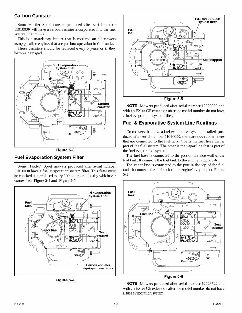
Carbon Canister
Some Hustler Sport mowers produced after serial number11010000 will have a carbon canister incorporated into the fuelsystem. Figure 5-3
This is a mandatory feature that is required on all mowersusing gasoline engines that are put into operation in California.
These canisters should be replaced every 5 years or if theybecome damaged.
Fuel Evaporation System Filter
Some Hustler® Sport mowers produced after serial number11010000 have a fuel evaporation system filter. This filter mustbe checked and replaced every 100 hours or annually whichevercomes first. Figure 5-4 and Figure 5-5
NOTE: Mowers produced after serial number 12023522 andwith an EX or CE extension after the model number do not havea fuel evaporation system filter.
Fuel & Evaporative System Line Routings
On mowers that have a fuel evaporative system installed, pro-duced after serial number 11010000, there are two rubber hosesthat are connected to the fuel tank. One is the fuel hose that ispart of the fuel system. The other is the vapor line that is part ofthe fuel evaporative system.
The fuel hose is connected to the port on the side wall of thefuel tank. It connects the fuel tank to the engine. Figure 5-6
The vapor line is connected to the port in the top of the fueltank. It connects the fuel tank to the engine’s vapor port. Figure5-5
NOTE: Mowers produced after serial number 12023522 andwith an EX or CE extension after the model number do not havea fuel evaporation system.
Figure 5-3
Figure 5-4
Carbon canister
Fuel evaporation system filter
Carbon canister equipped machines
Fuel evaporation system filter
Vapor line
Fuel tank
Seat support
Figure 5-5
Figure 5-6
Fuel evaporation system filter
Vapor line
Fuel tank
Seat support
Fuel tank
Fuel line
Seat support
REV E 5-2 108934

Engine RPM Settings
The engine rpm’s are set at the factory for maximum mowing efficiency. Occasionally it may be necessary to check and adjust thesettings. The idle speeds should be set as follows:
B&S 17.5/21 hp
ENGINE SPEED
MODEL NO. ENDING WITH: HIGH IDLE
MODEL NO. WITHOUT EXTENSIONMODEL NO. WITH EX EXTENSION
3600 ± 50 RPM
B&S 26 hp
ENGINE SPEED
MODEL NO. ENDING WITH: HIGH IDLE
MODEL NO. WITHOUT EXTENSIONMODEL NO. WITH EX EXTENSION
3600 ± 50 RPM
Kawasaki FR541 / FR600 / FR651
ENGINE SPEED
MODEL NO. ENDING WITH: HIGH IDLE
MODEL NO. WITHOUT EXTENSIONMODEL NO. WITH US EXTENSIONMODEL NO. WITH EX EXTENSION
3600 ± 50 RPM
Honda GXV530
ENGINE SPEED
MODEL NO. ENDING WITH: HIGH IDLE
MODEL NO. WITHOUT EXTENSIONMODEL NO. WITH EX EXTENSION
3600 ± 50 RPM
Kohler SV590
ENGINE SPEED
MODEL NO. ENDING WITH: LOW IDLE HIGH IDLE
MODEL NO. WITH EX EXTENSION 1900 ± 100 RPM 3600 ± 50 RPM
MODEL NO. WITH CE EXTENSION 1900 ± 100 RPM 2900 ± 50 RPM
Kohler SV715
ENGINE SPEED
MODEL NO. ENDING WITH: LOW IDLE HIGH IDLE
MODEL NO. WITH EX EXTENSION 1900 ± 50 RPM 3600 ± 50 RPM
MODEL NO. WITH CE EXTENSION 1900 ± 50 RPM 2900 ± 50 RPM
108934 5-3 REV E

NOTE: Model numbers may or may not end with an extension after the number. There are several different extensions that may beshown; i.e. EX or CE. Example: 922222 (no extension)
922222 EX922222 CE922222 US
REV E 5-4 108934

DECK ADJUSTMENTS
Deck Leveling
1. Park the mower on a hard, flat surface.2. Check tire pressures (8 – 12 psi) to make certain the tires
are properly inflated before starting to level deck.
3. Raise and lock deck into transport position.4. Place 3” high deck support blocks (two stacked 2” x 4”
blocks can be used to create a 3” high support) at the fourcorners of the deck as indicated. Figure 6-1, Figure 6-2,& Figure 6-3
5. Remove the deck stop pin and lower the deck until it restson the support blocks.
6. Loosen the three bolts attaching the three deck links tothe deck.
7. Push the lift pedal forward, place the deck stop pin in theindicator hole marked 3.25” and release the pedal.
8. Pull the pedal rearward so that the crank lever is heldfirmly against the stop pin and play in the pivot joint isremoved; secure the pedal in this position (a bungee cordmay be used).
9. Tighten the three deck links to the deck with the flangednuts clamping on either side of the slot with 48 ft.-lbs. oftorque. Release the lift pedal and ensure that the deck canbe raised and locked into the transport position. Figure 6-4 . .
WARNING
Stop engine. Make sure deck clutch switch is in the down(OFF) position. Remove ignition key. Place steering con-trol levers in the park brake position. Make sure bladesare stopped before leaving seat.
Figure 6-1
Block
Block
Block
Block
Figure 6-2
Figure 6-3
Block
BlockBlock
Block
BlockBlock
Block
Block
108934 6-1 REV E
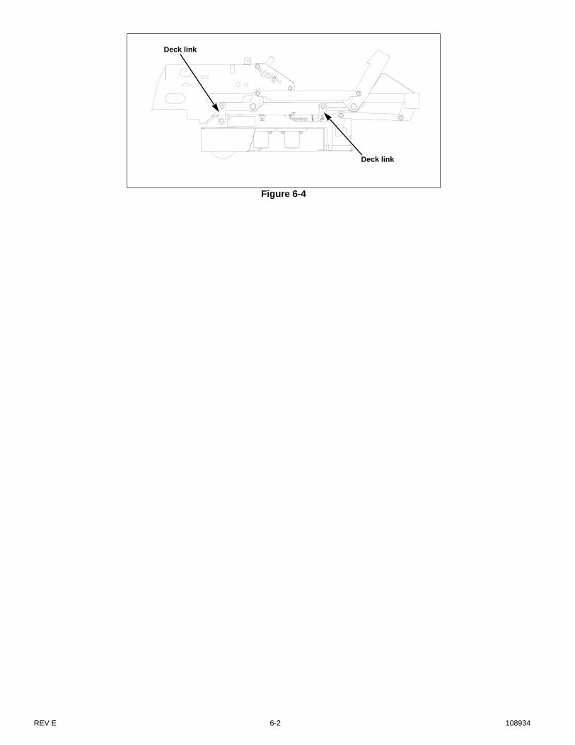
Figure 6-4
Deck link
Deck link
REV E 6-2 108934

Blades
Mower blade maintenanceCheck the mower blades daily, they are the key to power effi-
ciency and well groomed turf. Keep the blades sharp. A dullblade will tear rather than cut the grass, leaving a brown raggedtop on the grass within a few hours. A dull blade also requiresmore power from the engine.
Replace any blade which is bent, cracked or broken.
Mower blade removalUse a 15/16” wrench to remove the 5/8” cap screw holding
the blade to the spindle shaft from underneath. NOTE: A bladeholding tool (part number 381442) is available from Hustler®
Turf Equipment. It is designed to prevent the blades from rotat-ing when they are being removed or installed on the spindle.Contact your Hustler® dealer for more information.
Sharpen the blades on a grinder following pattern as shown(Figure 6-5). Touch-up sharpening can be done with a file
Check the blades for balance following grinding. A commer-cial balancing tool is available through most hardware supplystores, or balancing can be done by placing the blade on aninverted line punch or 5/8” bolt. Blade should not lean or tilt.Spin the blade slowly, blade should not wobble. If blade is outof balance, true it up before reinstalling.
Lay the blade on a flat surface and check for distortion (Fig-ure 6-6 & Figure 6-7). Replace any distorted blade.
Do not re-use spindle bolts which have stripped, worn orundercut threads. Torque bolts on spindles to 118 foot-pounds(160.0 N-m) when reinstalling blades.
Properly compressed cup washers maintain the correct com-
pression load on the blades. Replace the cup washers if they arecracked or flattened.
IMPORTANT: The blade sail (curved part) must be point-ing upward toward the inside of the deck to ensure proper cut-ting.
IMPORTANT: When mounting blades, rotate them afterinstallation to ensure blade tips do not touch each other or sidesof the mower.
WARNING
Never attempt to straighten a bent blade by heating, orweld a cracked or broken blade as the blade may breakand cause serious injury. Replace worn or damagedblades.
WARNING
Never work with blades while engine is running or deckclutch switch is engaged (on). Always place deck clutchswitch in the disengaged position, place steering controllevers in the park brake position and turn engine off anddisconnect negative battery cable. Block up mower whenyou must work under it. Wear gloves when handlingblades. Always check for blade damage if mowerstrikes a rock, branch or other foreign object during mow-ing!
WARNING
Always wear adequate eye protection when grindingmower blades.
WARNING
Failure to correctly torque the bolt may result in the lossof the blade which can cause serious injury.
WARNING
Mower blades are sharp and can cut. Wrap the blade(s) orwear gloves and use extra caution when servicing them.
Figure 6-5
Figure 6-6
Resharpening pattern
Do not sharpen to original pattern (below). It is easier to get a straight cutting edge following
the resharpening pattern shown above.
Original edge
Warped Blade (Replace)
Straight Blade
Cutting plane
Comparison of Warped and Straight Blades
108934 6-3 REV E
Belts
Inspect belts frequently for wear and serviceability. Replace abelt that shows signs of severe cuts, tears, separation, weatherchecking and cracking, or burns caused by slipping. Slight rav-eling of belt covering does not indicate failure, trim ravelingswith a sharp knife.
Inspect the belt pulley grooves and flanges for wear. A newbelt, or one in good condition, should never run against the bot-tom of the groove. Replace the pulley when this is the case, oth-erwise, the belt will lose power and slip excessively.
Never pry a belt to get it on a pulley as this will cut or damagethe fibers of the belt covering.
Keep oil and grease away from belts, and never use belt dress-ings. Any of these will destroy the belt composition in a veryshort time.
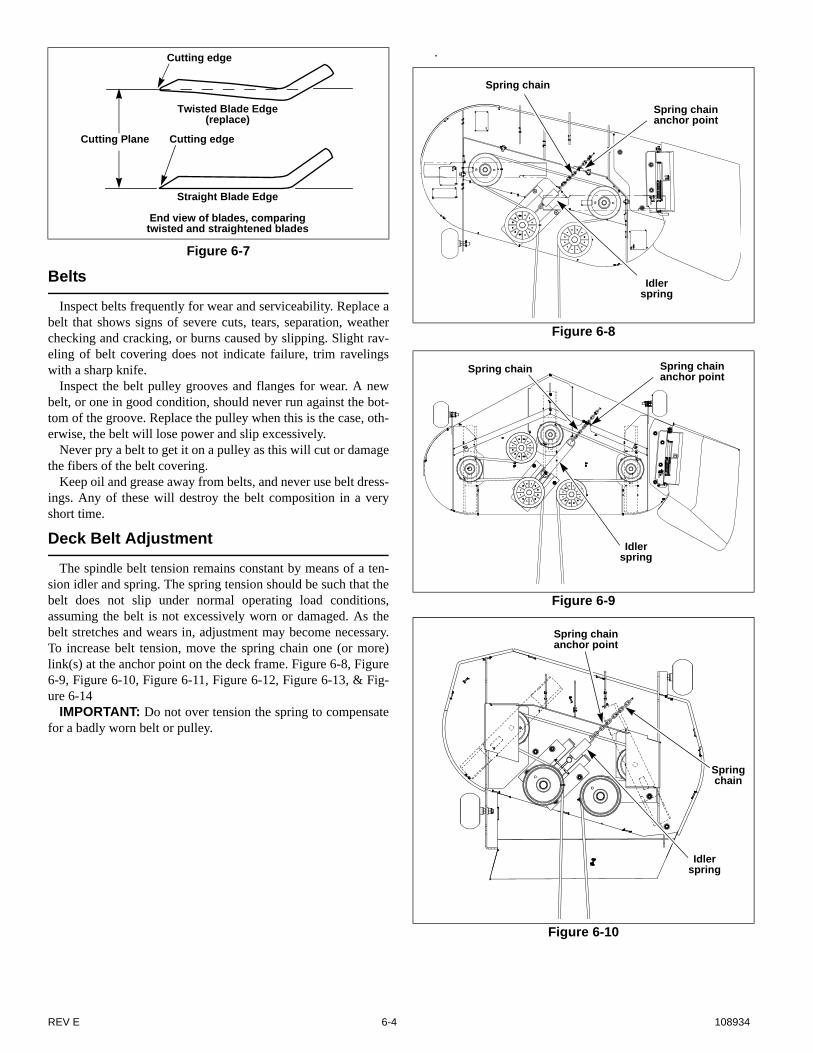
Deck Belt Adjustment
The spindle belt tension remains constant by means of a ten-sion idler and spring. The spring tension should be such that thebelt does not slip under normal operating load conditions,assuming the belt is not excessively worn or damaged. As thebelt stretches and wears in, adjustment may become necessary.To increase belt tension, move the spring chain one (or more)link(s) at the anchor point on the deck frame. Figure 6-8, Figure6-9, Figure 6-10, Figure 6-11, Figure 6-12, Figure 6-13, & Fig-ure 6-14
IMPORTANT: Do not over tension the spring to compensatefor a badly worn belt or pulley.
.
Figure 6-7
Cutting edge
Twisted Blade Edge (replace)
Cutting edgeCutting Plane
Straight Blade Edge
End view of blades, comparing twisted and straightened blades
Figure 6-8
Figure 6-9
Figure 6-10
Spring chain
Spring chain anchor point
Idler spring
Spring chain Spring chain anchor point
Idler spring
Spring chain
Spring chain anchor point
Idler spring
REV E 6-4 108934
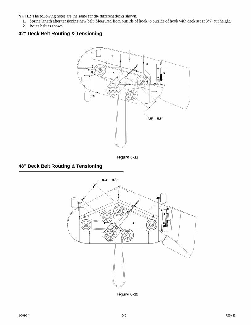
NOTE: The following notes are the same for the different decks shown.1. Spring length after tensioning new belt. Measured from outside of hook to outside of hook with deck set at 3¼" cut height.2. Route belt as shown.
42" Deck Belt Routing & Tensioning
48" Deck Belt Routing & Tensioning
Figure 6-11
4.5” – 5.5”
Figure 6-12
8.3” – 9.3”
108934 6-5 REV E
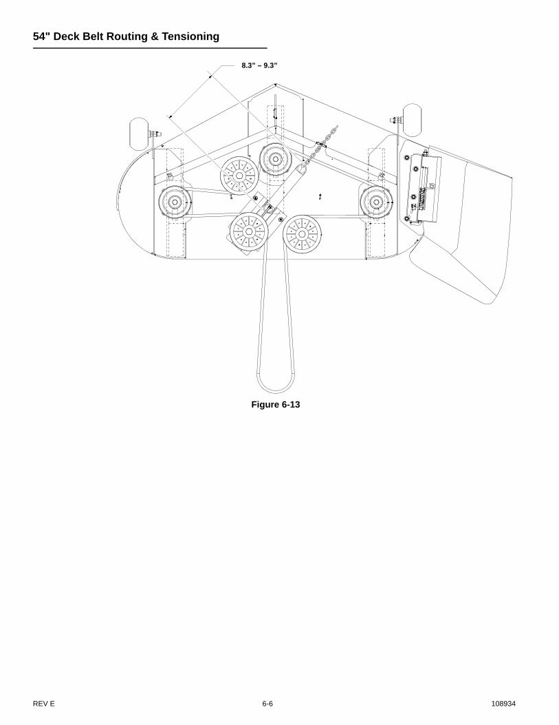
54" Deck Belt Routing & Tensioning
Figure 6-13
8.3” – 9.3”
REV E 6-6 108934

36" RD Deck Belt Routing & Tensioning
Figure 6-14
4.5” – 5.5”
108934 6-7 REV E

REV E 6-8 108934
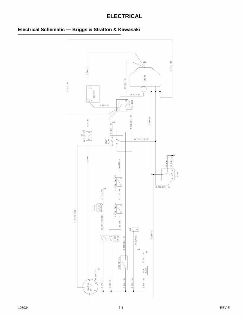
ELECTRICAL
Electrical Schematic — Briggs & Stratton & Kawasaki
108934 7-1 REV E
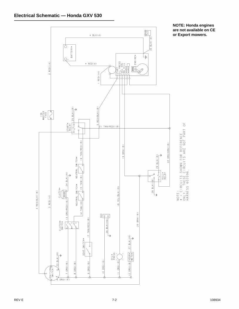
Electrical Schematic — Honda GXV 530
NOTE: Honda engines are not available on CE or Export mowers.
REV E 7-2 108934

Electrical Schematic — Kohler
NOTE: Kohler engines are not available on domestic mowers.
108934 7-3 REV E

REV E 7-4 108934

MAINTENANCE
NOTES:1. Initial oil change is after 5 hours of operation. Thereafter, change oil after every 40 hours operation. Change more often under dusty or dirty conditions and dur-
ing hot weather periods.2. Torque initially and after first 2 hours of operation.3. Change engine oil filter per the engine manufacturer’s recommendations. Refer to Engine Owner’s Manual for recommendations and other maintenance items..4. Service more often under dusty or dirty conditions.5. Pump drive belt only - Inspect every 6 months or 100 hours and replace if worn or cracking is noticed. Otherwise, replace every 200 hours or 2 years
whichever comes first.6. Check fuel system for any crack or leaks including, but not limit to, fuel line hoses, fuel valve, vent line hoses, vent valve, vapor valve, carbon canister, and
grommets. Repair as needed.7. More often under dusty or dirty conditions and during hot weather.8. Inspect ROPS after the first 20 hours of operation and then after every 100 hours of operation or yearly whichever comes first.
REFERENCES:A. Refer to engine owner’s manual for engine service information.NOTE: After completing maintenance cycle (100 hours), repeat cycle.
Maintenance ScheduleRefer to Figure 8-1, Figure 8-2, Figure 8-3,
Figure 8-4, Figure 8-5, Figure 8-6 & Figure 8-7
SERVICE ATINTERVALS INDICATED
WEEKLYOR 40
HOURS
ANNUALLYOR 100HOURS
Verify safety start interlock system Prior to each use
Visually inspect unit for loose hardware and/or damaged parts Prior to each use
Visually inspect tires Prior to each use
Check oil level, engine (1) Prior to each use or every 4 hours
Clean air intake screen (4) Prior to each use or every 4 hours
Clean foam element (if equipped) (4) Prior to each use
Check fuel level Prior to each use
Blades - sharpen & securely fastened Prior to each use
Discharge chute - securely in place & in lowest position Prior to each use
Clean engine and transaxle compartment Daily
Grease deck height pivots X
Grease front wheel bearings X
Grease deck lift pedal pivot X
Change engine oil & filter (1)(3) X
Check battery connections X
Check tire pressure with a gauge X
Clean engine exterior (a) X
Replace air cleaner paper element (if equipped) (4) X
Check pump & deck belt tension and condition (5) X
Check fuel lines (6) X
Check fuel tank grommet (6) X
Tighten lug nuts on wheels (2) X
Change fuel filter (6) X
Check ROPS mounting hardware (8) X
Replace fuel evaporation system filter (7) X
108934 8-1 REV E
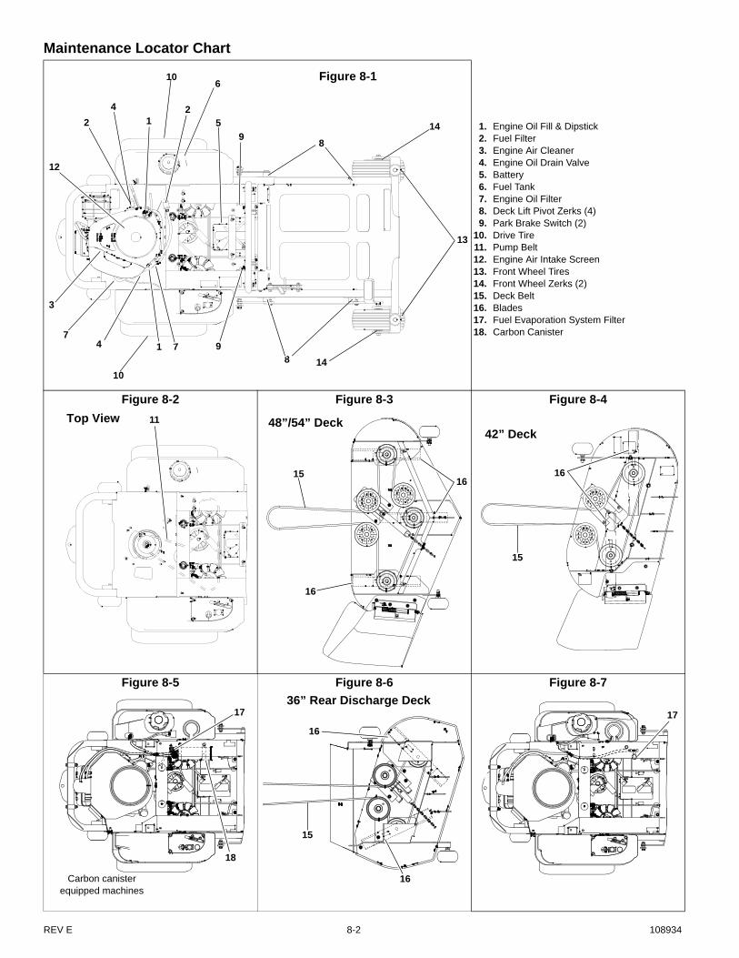
Maintenance Locator Chart
1. Engine Oil Fill & Dipstick2. Fuel Filter3. Engine Air Cleaner4. Engine Oil Drain Valve5. Battery6. Fuel Tank7. Engine Oil Filter8. Deck Lift Pivot Zerks (4)9. Park Brake Switch (2)
10. Drive Tire 11. Pump Belt12. Engine Air Intake Screen13. Front Wheel Tires14. Front Wheel Zerks (2)15. Deck Belt16. Blades17. Fuel Evaporation System Filter18. Carbon Canister
Figure 8-2 Figure 8-3 Figure 8-4
Figure 8-5 Figure 8-6 Figure 8-7
Figure 8-16
5
914
8
2
4
1
12
7
3
13
1489
10
4 1 7
2
10
11Top View
1615
16
48”/54” Deck
16
15
42” Deck
17
Carbon canister equipped machines
18
16
15
36” Rear Discharge Deck
16
17
REV E 8-2 108934

TROUBLESHOOTING
The majority of operating problems that occur with a system can be traced to improper adjustments or delayed service. Aconsistently applied preventative maintenance program will prevent many problems. The following chart is designed to help youlocate a problem by suggesting probable causes and the recommended solutions.
SYMPTOMSPROBABLE
CAUSESSUGGESTEDREMEDIES
Starting motor does not crank
Steering control levers not in park brake position or switch not adjusted
Place steering control levers in park brake posi-tion or re-adjust switch
Deck clutch switch engaged
Disengage clutch switch
Weak or dead battery Recharge or replace
Electrical connections are corroded or loose
Check the electrical con-nections
15 amp fuse is blown Replace the 15 amp fuse
For additional causes See engine manual
The engine will not start, starts hard or fails to keep running
No fuel or line plugged Fill tank or replace line (See Fuel System section for more details)
There is incorrect fuel in the fuel system
Drain the tank and replace the fuel with the proper type
There is dirt in the fuel filter Replace the fuel filter
Dirt, water or stale fuel in the fuel system
Contact your Dealer
The choke is not on Move the choke lever to ON
Numerous See engine manual
Engine:Runs with continuous mis-firing or engine runs unevenly or erratically
Numerous See engine manual
Loss of power or system will not operate in either direction
Restrictions in air cleaner Service air cleaner
Poor compression Contact your Dealer
Steering linkage needs adjustment
Adjust linkage
Tow valve open Close tow valve
The traction drive belt is worn, loose or broken
Install a new traction drive belt
Air in system Check filter and fittings
For additional causes See engine manual
Air cooled engine over-heating
Air intake screen or clean-ing fins clogged
Clean screen and fin
For additional causes See engine manual
Low engine oil pressure Low oil level Add oil
Oil diluted or too light Change oil and check for source of contamination
Failed oil pump Contact your Dealer
High oil consumption Numerous Contact your Dealer
Mower jerky when starting or operates in one direc-tion only
Steering control linkage needs adjustment
Adjust linkage
Loose steering linkage Tighten linkage
Transaxle component faulty Contact your Dealer
Mower creeps when steering control levers are in neutral
Steering linkage needs adjustment
Adjust linkage
Mower circles or veers in one direction
Steering linkage needs adjustment
Adjust linkage
Loose steering linkage Tighten linkage
Tires improperly inflated Adjust air pressure to 8 - 12 psi (55 - 83 KPa)
Transaxle component faulty Contact your Dealer
Mower creeps when park-ing brake engaged
Steering linkage out of adjustment
Adjust steering linkage
Brakes need adjustment Adjust parking brakes
There is abnormal vibra-tion
The engine mounting bolts are loose
Tighten the engine mount-ing bolts
The engine pulley, idler pul-ley or blade pulley is loose
Tighten the appropriate pul-ley
The engine pulley is dam-aged
Contact your Dealer
The cutting blade(s) is/are bent or unbalanced
Install new cutting blade(s)
A blade mounting bolt is loose
Tighten the blade mounting bolt
Spindle bearing is worn or loose
Replace or tighten spindle bearing
A blade spindle is bent Contact your Dealer
Blades do not rotate The deck drive belt is worn, loose or broken
Install a new deck drive belt
The deck drive belt is off the pulley
Install the deck drive belt and check for a reason
Electric clutch is not engag-ing
Check and/or replace 10 amp fuse.Contact your Dealer
Uneven cutting height The blade(s) are not sharp Sharpen the blades
A cutting blade(s) is/are bent
Install new cutting blade(s)
The deck is not level Level the deck per the Deck leveling and height adjustment section of the General Service Manual
An anti-scalp wheel is not set correctly
Adjust the height of the anti-scalp wheel
The underside of the deck is dirty
Clean the underside of the deck
Tires improperly inflated Adjust air pressure to 8 - 12 psi (55 - 83 KPa)
A blade spindle is bent Contact your Dealer
SYMPTOMSPROBABLE
CAUSESSUGGESTEDREMEDIES
108934 9-1 REV E

REV E 9-2 108934

108934 i-1 REV E
INDEXPAGE PAGE
Belts ..................................................................4-4, 6-4
Blades ......................................................................6-3
Carbon Canister ......................................................5-2
Deck Belt adjustment ..............................................6-4
Deck Belt Routing & Tensioning ............................6-5
Deck leveling ...........................................................6-1
Electrical Schematic ...............................................7-1
Engine air filter ........................................................5-1
Engine oil and filter .................................................5-1
Engine RPM settings ..............................................5-3
Fuel & Evaporative System Line Routings ............5-2
Fuel evaporation system filter ................................5-2
General engine maintenance .................................5-1
General maintenance precautions .........................2-2
Hustler service program .........................................1-1
Hydraulic pump belt adjustment ............................4-4
Maintenance introduction .......................................1-1
Maintenance locator chart ..................................... 8-2
Maintenance precautions ...................................... 2-2
Mower blade maintenance .................................... 6-3
Mower blade removal ............................................. 6-3
Operate machine safely ......................................... 2-2
Operation Precautions ........................................... 2-2
Park brake spring adjustment ............................... 4-3
Pre-operation precautions ..................................... 2-1
Safe servicing practices ......................................... 2-1
Service Program ..................................................... 1-1
Special Torques ..................................................... 3-1
Standard torques .................................................... 3-1
Steering adjustments ............................................. 4-1
Steering control lever neutral adjustment ............ 4-1
Steering damper ..................................................... 4-2
Tires ........................................................................ 4-4
Warranty ................................................................. 1-1