hy18-0024 dump catalog cilindroos compact ad or
TRANSCRIPT

Mobile CylindersDump Product Information, QuickReference Data & Application Guide
Catalog HY18-0024/US 03/01/06
2 Parker Hannifin CorporationMobile Cylinder DivisionYoungstown, OH
© Copyright 2006, Parker Hannifin Corporation, All Rights Reserved
FAILURE OR IMPROPER SELECTION OR IMPROPER USE OF THE PRODUCTS AND/OR SYSTEMS DESCRIBED HEREIN OR RELATED ITEMS CAN CAUSE DEATH, PERSONALINJURY AND PROPERTY DAMAGE.
This document and other information from Parker Hannifin Corporation, its subsidiaries and authorized distributors provide product and/or system options for further investigation by usershaving technical expertise. It is important that you analyze all aspects of your application and review the information concerning the product or system in the current product catalog. Dueto the variety of operating conditions and applications for these products or systems, the user, through its own analysis and testing, is solely responsible for making the final selection ofthe products and systems and assuring that all performance, safety and warning requirements of the application are met.
The products described herein, including without limitation, product features, specifications, designs, availability and pricing, are subject to change by Parker Hannifin Corporation and itssubsidiaries at any time without notice.
WARNING
The items described in this document are hereby offered for sale by Parker Hannifin Corporation, its subsidiaries or its authorized distributors. This offer and its acceptance are governedby the provisions stated in the "Offer of Sale".
Offer of Sale
3 Parker Hannifin CorporationMobile Cylinder DivisionYoungstown, OH
Table of Contents
Features and Benefits ..............................................................................................................4
Hydraulic Cylinder Model Number Coding ............................................................................5
Mounting Options and Code Chart .........................................................................................6
Hydraulic Cylinder Load & Displacements ............................................................................7
Closed Length Calculations for Single-Acting Single & Multiple Stage Cylinders ............8
Safety Precautions for Single-Acting Telescopic Cylinders ...............................................10
Genuine Replacement Service Repair Kits ..........................................................................12
Hydraulic Cylinder Required Service Tools .........................................................................13
Normal Maintenance Items ....................................................................................................14
Hydraulic Oil Recommendations .......................................................................................... 15
Standard Test Procedure for Hydraulic Cylinders ...............................................................16
Storage and Installation.........................................................................................................17
Front Mount Dump Body Stroke & Lifting Calculations...................................................... 18
Commodities & Materials Approximate Weights .................................................................19
Dump Hoist Type Identification Chart ...................................................................................20
Dump Trailer Type Identification Chart .................................................................................21
Single-Acting Telescopic Cylinders With CC, DB, and DC MountsDesign ........................22
Safety Guidelines for .............................................................................................................32
Offer of Sale ............................................................................................................................33
4 Parker Hannifin CorporationMobile Cylinder DivisionYoungstown, OH
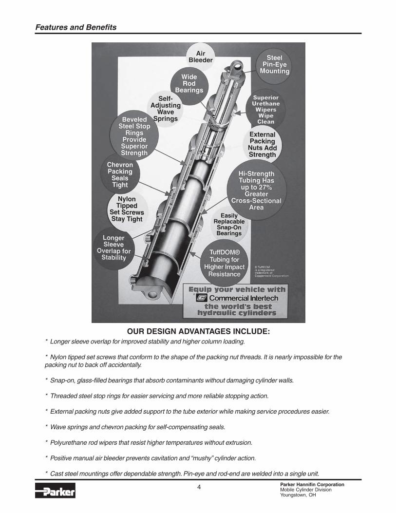
* Longer sleeve overlap for improved stability and higher column loading.
* Nylon tipped set screws that conform to the shape of the packing nut threads. It is nearly impossible for thepacking nut to back off accidentally.
* Snap-on, glass-filled bearings that absorb contaminants without damaging cylinder walls.
* Threaded steel stop rings for easier servicing and more reliable stopping action.
* External packing nuts give added support to the tube exterior while making service procedures easier.
* Wave springs and chevron packing for self-compensating seals.
* Polyurethane rod wipers that resist higher temperatures without extrusion.
* Positive manual air bleeder prevents cavitation and “mushy” cylinder action.
* Cast steel mountings offer dependable strength. Pin-eye and rod-end are welded into a single unit.
OUR DESIGN ADVANTAGES INCLUDE:
Features and Benefits
5 Parker Hannifin CorporationMobile Cylinder DivisionYoungstown, OH
Hydraulic Cylinder Model Number Coding
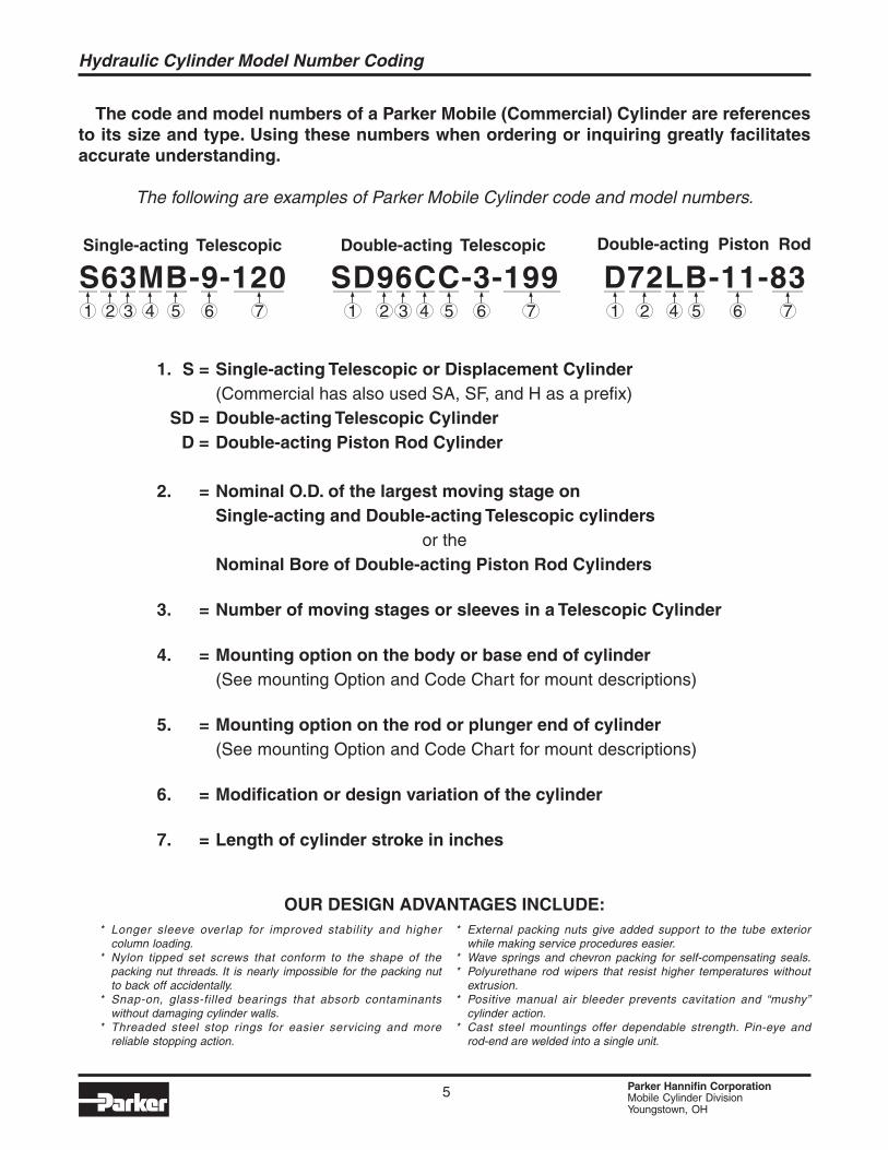
The code and model numbers of a Parker Mobile (Commercial) Cylinder are referencesto its size and type. Using these numbers when ordering or inquiring greatly facilitatesaccurate understanding.
The following are examples of Parker Mobile Cylinder code and model numbers.
1. S = Single-acting Telescopic or Displacement Cylinder(Commercial has also used SA, SF, and H as a prefix)
SD = Double-acting Telescopic CylinderD = Double-acting Piston Rod Cylinder
2. = Nominal O.D. of the largest moving stage onSingle-acting and Double-acting Telescopic cylinders
or theNominal Bore of Double-acting Piston Rod Cylinders
3. = Number of moving stages or sleeves in a Telescopic Cylinder
4. = Mounting option on the body or base end of cylinder(See mounting Option and Code Chart for mount descriptions)
5. = Mounting option on the rod or plunger end of cylinder(See mounting Option and Code Chart for mount descriptions)
6. = Modification or design variation of the cylinder
7. = Length of cylinder stroke in inches
* Longer sleeve overlap for improved stability and highercolumn loading.
* Nylon tipped set screws that conform to the shape of thepacking nut threads. It is nearly impossible for the packing nutto back off accidentally.
* Snap-on, glass-filled bearings that absorb contaminantswithout damaging cylinder walls.
* Threaded steel stop rings for easier servicing and morereliable stopping action.
* External packing nuts give added support to the tube exteriorwhile making service procedures easier.
* Wave springs and chevron packing for self-compensating seals.* Polyurethane rod wipers that resist higher temperatures without
extrusion.* Positive manual air bleeder prevents cavitation and “mushy”
cylinder action.* Cast steel mountings offer dependable strength. Pin-eye and
rod-end are welded into a single unit.
OUR DESIGN ADVANTAGES INCLUDE:

6 Parker Hannifin CorporationMobile Cylinder DivisionYoungstown, OH
Mounting Options and Code Chart
A
B
C
D
E
F
G
H
J
K
L
M
N
O
P
Pin-Eye DrilledThru Rod
Pin-Eye DrilledThru Lug
PlainNo Mount
Cross Tube
Threaded
Drilledand Tapped
Flange Mountat Base
Flange MountMid-Body
Foot / Pad Mount
CenterlineMount
Double LugClevis Mount
TrunnionMount
Rod End Drilledand Tapped
Ball Mount
Socket Mount
Body or Rod
Rod
Body or Rod
Body or Rod
Body or Rod
Body or Rod
Body
Body
Body
Body
Body or Rod
Body
Rod
Body or Rod
Body or Rod
CodeLetter
MountDescription
MountSketch
MountLocation
7 Parker Hannifin CorporationMobile Cylinder DivisionYoungstown, OH
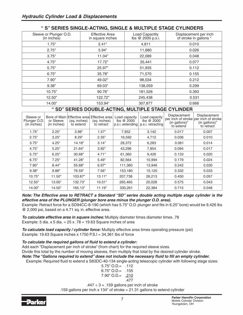
Hydraulic Cylinder Load & Displacements
“ S” SERIES SINGLE-ACTING, SINGLE & MULTIPLE STAGE CYLINDERS
“ SD” SERIES DOUBLE-ACTING, MULTIPLE STAGE CYLINDER
Note: The Effective area to RETRACT a Standard “SD” series double acting multiple stage cylinder is theeffective area of the PLUNGER (plunger bore area minus the plunger O.D. area).Example: Retract force for a SD94CC-8-190 (which has 5.75” O.D. plunger and fits in 6.25” bore) would be 9,426 lbs@ 2,000 psi, based on a 4.71 sq. in. effective area.
To calculate effective area in square inches: Multiply diameter times diameter times .78Example: 5 dia. x 5 dia. = 25 x .78 = 19.63 Square inches of area
To calculate load capacity / cylinder force: Multiply effective area times operating pressure (psi)Example: 19.63 Square inches x 1750 P.S.I = 34,361 lbs of force
To calculate the required gallons of fluid to extend a cylinder:Add each “Displacement per inch of stroke” (from chart) for the required sleeve sizes.Divide this total by the number of moving sleeves, then multiply that total by the desired cylinder stroke.Note: The “Gallons required to extend” does not include the necessary fluid to fill an empty cylinder.
Example: Required fluid to extend a S83DC-40-134 single-acting telescopic cylinder with following stage sizes:5.75" O.D.= .1126.75" O.D.= .1557.90" O.D.= .210
.477.447 ÷ 3 = .159 gallons per inch of stroke
.159 gallons per inch x 134" of stroke = 21.31 gallons to extend cylinder
Sleeve or Plunger O.D.(in inches)
Effective Areain square inches
Load Capactitylbs @ 2000 p.s.i.
Displacement per inchof stroke in gallons *
1.75" 2.41" 4,811 0.010
2.75" 5.94" 11,880 0.026
3.75" 11.04" 22,089 0.048
4.75" 17.72" 35,441 0.077
5.75" 25.97" 51,935 0.112
6.75" 35.78" 71,570 0.155
7.90" 49.02" 98,034 0.212
9.38" 69.03" 138,059 0.299
10.75" 90.76" 181,526 0.393
12.50" 122.72" 245,438 0.531
14.00" 153.94" 307,877 0.666
Sleeve orPlunger O.D.(in inches)
Bore of Mainor Sleeve(in inches)
Effective area(sq. inches)to extend
Effective area(sq. inches)to retract
Load capacitylbs @ 2000
p.s.i. extending
Load capacitylbs @ 2000
p.s.i. retracting
Displacementper inch of stroke
(in gallons)*to extend
Displacementper inch of stroke
(in gallons)*to retract
1.75" 2.25" 3.98" 1.57" 7,952 3,142 0.017 0.007
2.75" 3.25" 8.29" 2.35" 16,592 4,712 0.036 0.010
3.75" 4.25" 14.18" 3.14" 28,372 6,283 0.061 0.014
4.75" 5.25" 21.64" 3.92" 43,296 7,854 0.094 0.017
5.75" 6.25" 30.68" 4.71" 61,360 9,426 0.133 0.020
6.75" 7.25" 41.28" 5.49" 82,564 10,994 0.179 0.024
7.90" 8.44" 55.68" 6.97" 111,360 13,946 0.242 0.030
9.38" 9.88" 76.59" 7.56" 153,180 15,120 0.332 0.033
10.75" 11.50" 103.87" 13.11" 207,738 26,213 0.450 0.057
12.50" 13.00" 132.73" 10.01" 265,465 20,028 0.575 0.043
14.00" 14.50" 165.13" 11.19" 330,261 22,384 0.715 0.048
8 Parker Hannifin CorporationMobile Cylinder DivisionYoungstown, OH
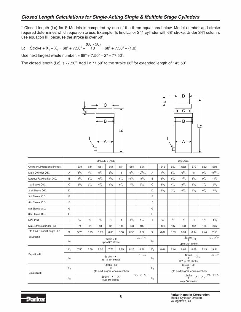
* Closed length (Lc) for S Models is computed by one of the three equations below. Model number and strokerequired determines which equation to use. Example: To find Lc for S41 cylinder with 68” stroke. Under S41 column,use equation III, because the stroke is over 50”.
(68 - 50)Lc = Stroke + X
1 + X
2 = 68” + 7.50” + 10 = 68” + 7.50” + (1.8)
Use next largest whole number. = 68” + 7.50” + 2” = 77.50”.
The closed length (Lc) is 77.50”. Add Lc 77.50” to the stroke 68” for extended length of 145.50”
AI
B
Lc
C1
8/
Lc
D
A
C
I
B
18/
SINGLE STAGE 2 STAGE
S31 S41 S51 S61 S71 S81 S91 S42 S52 S62 S72 S82 S92
A 33/4 43/4 53/4 63/4 8 91/8 1013/16 A 43/4 53/4 63/4 8 91/8 1013/16
B 43/8 53/8 63/8 73/8 85/8 97/8 113/4 B 53/8 63/8 73/8 85/8 97/8 113/4
C 23/4 33/4 43/4 53/4 63/4 77/8 93/8 C 33/4 43/4 53/4 63/4 77/8 93/8
D D 23/4 33/4 43/4 53/4 63/4 77/8
E E
F F
Cylinder Dimensions (inches)
Main Cylinder O.D.
Largest Packing Nut O.D.
1st Sleeve O.D.
2nd Sleeve O.D.
3rd Sleeve O.D.
4th Sleeve O.D.
H
G
H
G
I 3/43/4
3/4 1 1 11/4 11/4 I 3/43/4 1 1 11/4 11/4
71 84 88 95 118 128 190 126 137 138 164 186 265
X 5.75 5.75 5.75 6.00 6.00 6.50 6.62 X 6.69 6.69 6.94 6.94 7.44 7.56
LCStroke + X
up to 35" strokeLC
Stroke+ X2
up to 35" stroke
X1 7.50 7.50 7.50 7.75 7.75 8.25 8.38 X1 8.44 8.44 8.69 8.69 9.19 9.31
O.L. = 3” + X2O.L. = 3” + X2
O.L. = 3”O.L. = 3”
O.L. = 1 / ”1
4O.L. = 1 / ”1
4
LCStroke + X1
36" to 50" strokeLC
Stroke+ X 12
36" to 50" stroke
X2
Stroke - 5010
(To next largest whole number)X2
Stroke - 5020
(To next largest whole number)
LCStroke + X1 + X2over 50" stroke
LC
Stroke+ X 1 + X 22
over 50" stroke
6th Sleeve O.D.
5th Sleeve O.D.
NPT Port
Max. Stroke at 2000 PSI
Equation I
*To Find Closed Length - Lc
Equation II
Equation III
Closed Length Calculations for Single-Acting Single & Multiple Stage Cylinders
9 Parker Hannifin CorporationMobile Cylinder DivisionYoungstown, OH
Lc
E
C
D
AI
B
18/
Lc
F
C
D
E
AI
B
18/
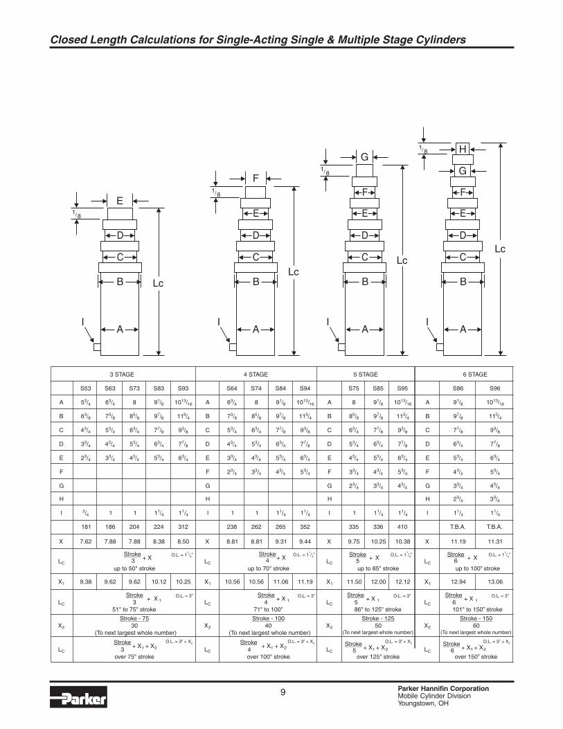
3 STAGE 4 STAGE
S53 S63 S73 S83 S93 S64 S74 S84 S94
A 53/4 63/4 8 91/8 1013/16 A 63/4 8 91/8 1013/16
B 63/8 73/8 85/8 97/8 113/4 B 73/8 85/8 97/8 113/4
C 43/4 53/4 63/4 77/8 93/8 C 53/4 63/4 77/8 93/8
D 33/4 43/4 53/4 63/4 77/8 D 43/4 53/4 63/4 77/8
E 23/4 33/4 43/4 53/4 63/4 E 33/4 43/4 53/4 63/4
F F 23/4 33/4 43/4 53/4
H
G
H
G
I 3/4 1 1 11/4 11/4 I 1 1 11/4 11/4
181 186 204 224 312 238 262 265 352
X 7.62 7.88 7.88 8.38 8.50 X 8.81 8.81 9.31 9.44
LC
Stroke+ X3
up to 50" strokeLC
Stroke+ X4
up to 70" stroke
X1 9.38
O.L. = 3” + X2O.L. = 3” + X2
O.L. = 3”O.L. = 3”
O.L. = 1 / ”1
4O.L. = 1 / ”1
4
9.62 9.62 10.12 10.25 X1 10.56 10.56 11.06 11.19
LC
Stroke+ X 13
51" to 75" strokeLC
Stroke+ X 14
71" to 100"
X2
Stroke - 7530
(To next largest whole number)X2
Stroke - 10040
(To next largest whole number)
LC
Stroke+ X1 + X23
over 75" strokeLC
Stroke+ X1 + X24
over 100" stroke
Lc
G
C
D
E
F
AI
B
18/
5 STAGE
S75 S85 S95
A 8 91/8 1013/16
B 85/8 97/8 113/4
C 63/4 77/8 93/8
D 53/4 63/4 77/8
E 43/4 53/4 63/4
F 33/4 43/4 53/4
H
G 23/4 33/4 43/4
I 1 11/4 11/4
335 336 410
X 9.75 10.25 10.38
LC
Stroke + X5up to 85" stroke
O.L. = 1 / ”1
4
O.L. = 3” + X2
O.L. = 3”
X1 11.50 12.00 12.12
LC
Stroke+ X 15
86" to 125" stroke
X2
Stroke - 12550
(To next largest whole number)
LC
Stroke+ X1 + X25
over 125" stroke
Lc
H
G
C
D
E
F
AI
B
18/
6 STAGE
A
B
C
D
E
F
H
G
I
X
LC
Stroke + X6up to 100” stroke
O.L. = 1 / ”1
4
O.L. = 3” + X2
O.L. = 3”
X1
LC
Stroke+ X 16
101" to 150” stroke
X2
Stroke - 15060
(To next largest whole number)
LC
Stroke+ X1 + X26
over 150” stroke
S86 S96
91/8 1013/16
97/8 113/4
77/8 93/8
63/4 77/8
53/4 63/4
43/4 53/4
2
3
3
3
/
/
4
4
3
4
3
3
/
/
4
4
11/4 11/4
T.B.A. T.B.A.
11.19 11.31
12.94 13.06
Closed Length Calculations for Single-Acting Single & Multiple Stage Cylinders
10 Parker Hannifin CorporationMobile Cylinder DivisionYoungstown, OH
WARNING!Telescopic cylinders commonly installed on dumping vehicles are devices intended toprovide only a lifting force. The cylinder is not a structural member, and is not designedfor, nor intended to provide stability to the dumping vehicle. Rollover or lateral tilt cancause the cylinder to bend, buldge or separate causing the dump body to drop suddenly,resulting in severe injury or death and/or damage to the unit and cylinder, if the followingwarnings are not observed.
Hydraulic cylinders are not to be used as a stabilizer on a dump body or dump trailer. The hydraulic cylinder will notprevent the dump body or trailer from rollover or lateral tilt. The cylinder is strictly a lifting device and is not astructural member of the unit. Cylinders are not to be used as a means of stabilizing the unit.
The hydraulic cylinder mounted in the unit should be free to find its own trajectory line of extension, free of any lateralloading of the plungers. Misalignment of the top or bottom mountings, or mounting pins too tight, may cause scoringof the plungers, leaking, or improper sequencing which could cause the unit to upset.
The hydraulic cylinder will not withstand lateral or side pressure when the unit is leaning. Only activate the cylinderwhen the tractor and trailer are in a straight line (not jack-knifed). A jackknife position of the tractor with the trailer isnot recommended when dumping. In a jackknifed position, the upper coupler pivots on bearings, contributing nothingto dump stability. When the tractor and trailer are straight, the coupler bearings are normally 34 inches apart, assistingin stabilizing the dump.
Do not activate the cylinder while on unlevel or soft ground, or during heavy crosswinds. Doing so may cause the unitto upset. Uneven terrain, causing the trailer wheels to be 3 1/2 inches to 4 inches higher than the other side, puts thetop of the body 12 inches to 14 inches off center when the cylinder is fully extended. On fresh fill, loaded trailerwheels may sink on one side, again setting up potential tip over. On road construction, the crown is also critical onspread application, as in dumping on a slope. A 4 inch plus, height differential of wheels on an axle 8 feet wide, isanother rollover potential. Do not attempt dumping operations in high gusty wind conditions. If possible, raise thedump body directly into the wind.
A blown tire or a severely under inflated tire can cause dump instability, when dumping. Always check tires visuallyfor cuts or punctures by nails and metal. Make sure all tires are inflated properly. Proper tire inflation also improveswear and fuel economy.
Do not activate the cylinder while personnel or equipment are alongside or behind the dump body or trailer.
A hung load is commodity that does not discharge when a dump body is raised to an elevated position. This conditionexists due to surface adhesion between the commodity and the interior of the dump body. To avoid a tip over due toa hung load, the driver should be warned by an observer or be aware of the material’s moisture content, if thiscondition exists, immediately lower the dump body.
The operator should stay at the controls during the entire dumping operation. An operator who fails to stay at thecontrols will never control the body when it starts to lean over for a tip over. If a problem exists, and the body startsto lean, the operator should immediately lower the dump body or trailer and check and remedy any potential problems,then resume dumping the load. It is important to slowly position the cylinder control valve into the hold position toavoid subjecting the cylinder to a high pressure.
Do not overload the unit. The load must be distributed evenly during loading or unloading to avoid rollover and lateraltilt. Loads stuck while the cylinder is partially or completely extended increases the hazard of rollover and lateral tilt.Lower the dump body or trailer entirely with the cylinder control valve partially open (avoid lowering the dump bodyor trailer with the cylinder control valve completely open). Then unload the dump body or trailer manually or with analternative mechanical aid.
Overloading is a very common occurrence that aggravates all the above conditions that cause a tip over.
Safety Precautions for Single-Acting Telescopic Cylinders
11 Parker Hannifin CorporationMobile Cylinder DivisionYoungstown, OH
Safety Precautions for Single-Acting Telescopic Cylinders
WARNING!Shock pressure can cause severe injury or death and/or damage to the unit and cylinder.
Do not use the cylinder to loosen loads stuck in the dump body or trailer. Lower the dump body or trailer entirely withthe cylinder control valve partially open (avoid lowering the dump body or trailer with the cylinder control valvecompletely open). Then unload the dump body or trailer manually or with an alternative mechanical aid.
Humping is a rapid acceleration / deceleration method used to loosen a hung load from a trailer. If the load is offcenter and the trailer is moved, a tip over may occur. Also, serious damage to the hoist may occur if an extremehumping motion is used to get a sticky load out of the body.
Do not move the truck and jam the brakes while the cylinder is partially or fully extended to loosen loads stuck in thedump body or trailer. Pulling forward (or backing up) and hitting the brakes, or lowering the body part way and thenquickly engaging the valve in the “HOLD” or “RAISE” position will cause a tremendous pressure spike. This pressurespike may bulge or split one of the larger stages of the cylinder. Lower the dump body or trailer entirely with thecylinder control valve partially open (avoid lowering the dump body or trailer with the cylinder control valve completelyopen). Then unload the dump body or trailer manually or with an alternative mechanical aid.
Do not move the truck until the dump body or trailer is lowered completely.
WARNING!Over pressurizing the cylinder can cause severe injury or death and/or damage to the unitand cylinder.
Do not operate a cylinder at pressures above factory recommended operating pressures (Normally 2,000 P.S.I.unless otherwise approved).
WARNING!Worn or damaged hydraulic hoses can cause severe injury or death and/or damage to theunit and cylinder.
Hydraulic hoses should be checked regularly and replaced if worn out or damaged.
NOTICE!
Do not drive the unit while the P.T.O. or hydraulic pump is engaged.
The hydraulic oil should be checked and changed regularly to avoid contamination leading to internal cylinder damage.
A damp to light film of oil on each plunger indicates a good cylinder operation. A small accumulation of oil may benoticed on the plunger at the head nuts after many cycles. This should not be mistaken for packing leakage.
Cylinder should be free of entrapped air. It is advisable to bleed air from the cylinder weekly to free entrapped air.This will result in a smoother operation.
The cylinder should float in the pin mountings. The cylinder should be installed with 1/8" to 3/16" of clearancebetween the pin and the pin hole if the mounting eye is wider than 5", or with 1/16" to 1/8" clearance if the mountingeye is less than 5" wide. There should be a clearance of 1/8" to 1/4" per side on eyes less than 5" wide and 1/4" to 1/2" clearance per side on eyes in excess of 5" wide. This is to allow the body to sway slightly while dumping, withoutputting a side load on the cylinder. The cylinder plunger or one of the sleeves should be extended a minimum of 1/4"when the dump body is in the down position.
The cylinder end mounts should be lubricated regularly.
12 Parker Hannifin CorporationMobile Cylinder DivisionYoungstown, OH
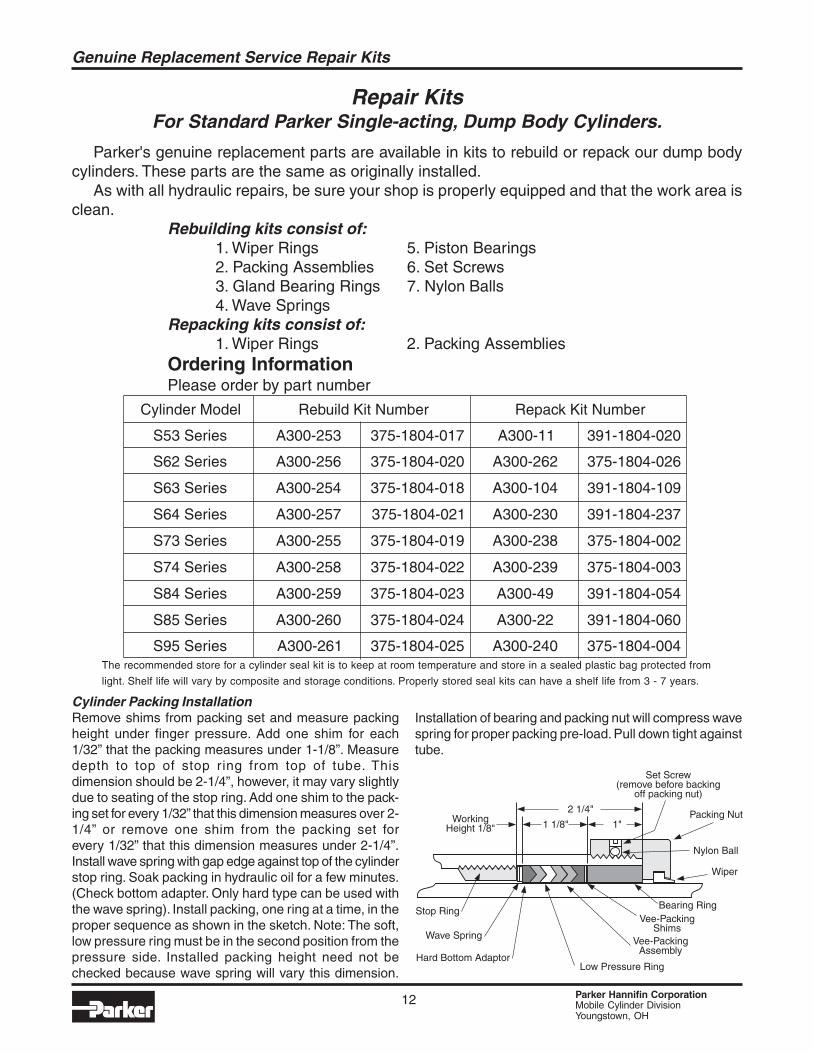
Repair KitsFor Standard Parker Single-acting, Dump Body Cylinders.
Parker's genuine replacement parts are available in kits to rebuild or repack our dump bodycylinders. These parts are the same as originally installed.
As with all hydraulic repairs, be sure your shop is properly equipped and that the work area isclean.
Rebuilding kits consist of:1. Wiper Rings 5. Piston Bearings2. Packing Assemblies 6. Set Screws3. Gland Bearing Rings 7. Nylon Balls4. Wave Springs
Repacking kits consist of:1. Wiper Rings 2. Packing Assemblies
Ordering InformationPlease order by part number
Cylinder Packing InstallationRemove shims from packing set and measure packingheight under finger pressure. Add one shim for each1/32” that the packing measures under 1-1/8”. Measuredepth to top of stop ring from top of tube. Thisdimension should be 2-1/4”, however, it may vary slightlydue to seating of the stop ring. Add one shim to the pack-ing set for every 1/32” that this dimension measures over 2-1/4” or remove one shim from the packing set forevery 1/32” that this dimension measures under 2-1/4”.Install wave spring with gap edge against top of the cylinderstop ring. Soak packing in hydraulic oil for a few minutes.(Check bottom adapter. Only hard type can be used withthe wave spring). Install packing, one ring at a time, in theproper sequence as shown in the sketch. Note: The soft,low pressure ring must be in the second position from thepressure side. Installed packing height need not bechecked because wave spring will vary this dimension.
Stop Ring
Wave Spring
Packing Nut
Set Screw(remove before backing
off packing nut)
Wiper
Vee-PackingAssembly
Vee-PackingShims
Bearing Ring
Low Pressure RingHard Bottom Adaptor
Nylon Ball
2 1/4"
1 1/8"WorkingHeight 1/8" 1"
Cylinder Model Rebuild Kit Number Repack Kit Number
S53 Series A300-253 375-1804-017 A300-11 391-1804-020
S62 Series A300-256 375-1804-020 A300-262 375-1804-026
S63 Series A300-254 375-1804-018 A300-104 391-1804-109
S64 Series A300-257 375-1804-021 A300-230 391-1804-237
S73 Series A300-255 375-1804-019 A300-238 375-1804-002
S74 Series A300-258 375-1804-022 A300-239 375-1804-003
S84 Series A300-259 375-1804-023 A300-49 391-1804-054
S85 Series A300-260 375-1804-024 A300-22 391-1804-060
S95 Series A300-261 375-1804-025 A300-240 375-1804-004
Installation of bearing and packing nut will compress wavespring for proper packing pre-load. Pull down tight againsttube.
Genuine Replacement Service Repair Kits
The recommended store for a cylinder seal kit is to keep at room temperature and store in a sealed plastic bag protected from
light. Shelf life will vary by composite and storage conditions. Properly stored seal kits can have a shelf life from 3 - 7 years.
13 Parker Hannifin CorporationMobile Cylinder DivisionYoungstown, OH
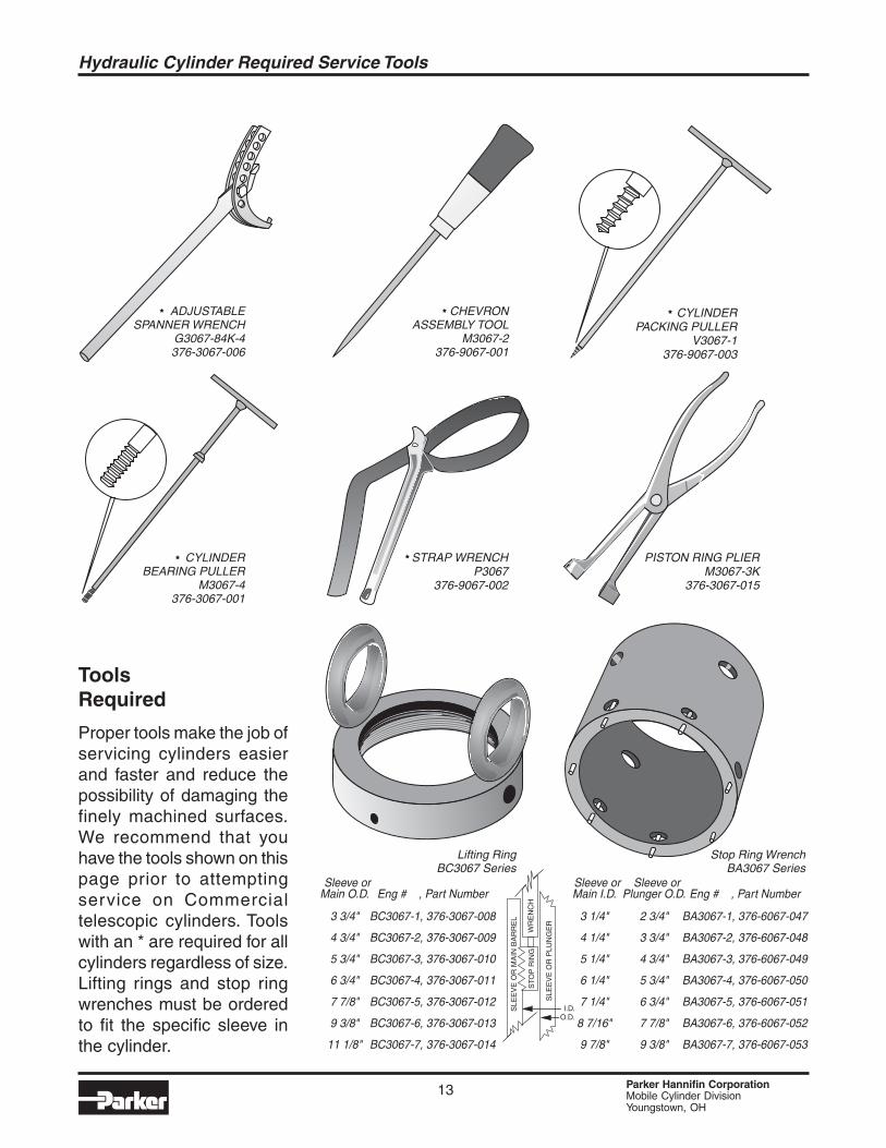
ToolsRequired
Proper tools make the job ofservicing cylinders easierand faster and reduce thepossibility of damaging thefinely machined surfaces.We recommend that youhave the tools shown on thispage prior to attemptingservice on Commercialtelescopic cylinders. Toolswith an * are required for allcylinders regardless of size.Lifting rings and stop ringwrenches must be orderedto fit the specific sleeve inthe cylinder.
ADJUSTABLESPANNER WRENCH
G3067-84K-4376-3067-006
CHEVRONASSEMBLY TOOL
M3067-2376-9067-001
CYLINDERPACKING PULLER
V3067-1376-9067-003
CYLINDERBEARING PULLER
M3067-4376-3067-001
STRAP WRENCHP3067
376-9067-002
PISTON RING PLIERM3067-3K
376-3067-015
Sleeve orMain O.D.
3 3/4"
4 3/4"
5 3/4"
6 3/4"
7 7/8"
9 3/8"
11 1/8"
Sleeve orPlunger O.D.
2 3/4"
3 3/4"
4 3/4"
5 3/4"
6 3/4"
7 7/8"
9 3/8"
Eng # , Part Number
BC3067-1, 376-3067-008
BC3067-2, 376-3067-009
BC3067-3, 376-3067-010
BC3067-4, 376-3067-011
BC3067-5, 376-3067-012
BC3067-6, 376-3067-013
BC3067-7, 376-3067-014
Eng # , Part Number
BA3067-1, 376-6067-047
BA3067-2, 376-6067-048
BA3067-3, 376-6067-049
BA3067-4, 376-6067-050
BA3067-5, 376-6067-051
BA3067-6, 376-6067-052
BA3067-7, 376-6067-053
Lifting RingBC3067 Series
Stop Ring WrenchBA3067 Series
Sleeve orMain I.D.
3 1/4"
4 1/4"
5 1/4"
6 1/4"
7 1/4"
8 7/16"
9 7/8"
STO
PR
ING
WR
EN
CH
SLE
EV
EO
RM
AIN
BA
RR
EL
O.D.I.D.
SLE
EV
EO
RP
LUN
GE
R
Hydraulic Cylinder Required Service Tools
14 Parker Hannifin CorporationMobile Cylinder DivisionYoungstown, OH
Packing, wipers and bushings are considered normal maintenance or service items. Theseitems are subject to contamination from external and internal foreign materials, many of whichare abrasive in nature, causing abnormal wear or damage to the parts, to the extent that replace-ments are required.
WARNING!!Before working on a telescopic cylinder mounted on a truck or trailer unit, use supports orholding devices that will absolutely prevent the body from accidentally lowering. Placecontrol valve in the “Lower” position to assure that all pressure has been relieved from thecylinder.
Because of our self-compensating Packing design, Standard Commercial HydraulicsCylinders require no packing adjustment. For Commercial Packing Assembly InstallationProcedure see Service Repair Kit Page.
Procedure for Adjusting Telescopic Cylinder Head Nuts.(For Cylinder designs using no Wave Springs and/or no U-Seals)
1.Loosen set screw (or set screws) in head nut that holds in packing of leaking stage.2.Lightly tap head nut around circumference with a hammer.3.Back head nut off 1/2 to 1 full turn using a spanner or chain wrench.
(Note: If stage rotates when head nut is turned, hold stage with a strap wrench.)4.Cycle cylinder 2 to 3 times to reset chevron vee packing.5.Retighten head nut approximately 1/2 turn further than it was when it was loosened.6.Tighten set screws.
Procedure for Mis-Staging or Mis-Sequencing Cylinder.
1.Loosen set screws in head nut that holds in packing which fits over stage that is sticking.2.Lightly tap head nut around circumference with a hammer.3.Back head nut off 1/2 turn using a spanner or chain wrench.4.Cycle cylinder, if cylinder still mis-stages, back head nut off another 1/2 turn.5.Cycle cylinder, if cylinder still mis-stages, tighten the head nut of the next stage that is extending.6.Tighten set screws.
Bleeding Air from Single-Acting Telescopic Cylinders.For smooth operation of these cylinders, it is advisable to bleed the air from the cylinder weekly.
Manual bleeding is accomplished by:
1.Empty the dump body of any material.2.Remove the cover plate from the dog house of the dump body to access the bleeder valve.3.Fully extend the cylinder, raising the EMPTY dump bed.4.Lower the dump to within 1 foot from resting on the frame.5.With the fingers, turn the bleeder valve in a counterclockwise direction. This opens the valve
and allows the air to escape from the cylinder.6.When a steady stream of oil comes from the bleeder, turn the valve in a clockwise direction
until it is closed.
If these procedures fail to correct the problem, please contact anAuthorized Service Center for Instructions.
Normal Maintenance Items
15 Parker Hannifin CorporationMobile Cylinder DivisionYoungstown, OH
Hydraulic Oil Recommendations
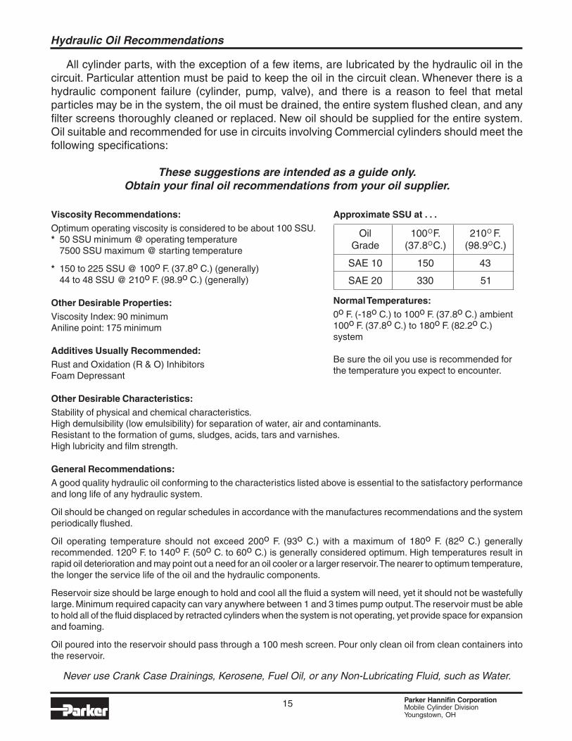
All cylinder parts, with the exception of a few items, are lubricated by the hydraulic oil in thecircuit. Particular attention must be paid to keep the oil in the circuit clean. Whenever there is ahydraulic component failure (cylinder, pump, valve), and there is a reason to feel that metalparticles may be in the system, the oil must be drained, the entire system flushed clean, and anyfilter screens thoroughly cleaned or replaced. New oil should be supplied for the entire system.Oil suitable and recommended for use in circuits involving Commercial cylinders should meet thefollowing specifications:
These suggestions are intended as a guide only.Obtain your final oil recommendations from your oil supplier.
Viscosity Recommendations:Optimum operating viscosity is considered to be about 100 SSU.* 50 SSU minimum @ operating temperature
7500 SSU maximum @ starting temperature
* 150 to 225 SSU @ 100o F. (37.8o C.) (generally)44 to 48 SSU @ 210o F. (98.9o C.) (generally)
Other Desirable Properties:Viscosity Index: 90 minimumAniline point: 175 minimum
Additives Usually Recommended:Rust and Oxidation (R & O) InhibitorsFoam Depressant
Other Desirable Characteristics:Stability of physical and chemical characteristics.High demulsibility (low emulsibility) for separation of water, air and contaminants.Resistant to the formation of gums, sludges, acids, tars and varnishes.High lubricity and film strength.
General Recommendations:A good quality hydraulic oil conforming to the characteristics listed above is essential to the satisfactory performanceand long life of any hydraulic system.
Oil should be changed on regular schedules in accordance with the manufactures recommendations and the systemperiodically flushed.
Oil operating temperature should not exceed 200o F. (93o C.) with a maximum of 180o F. (82o C.) generallyrecommended. 120o F. to 140o F. (50o C. to 60o C.) is generally considered optimum. High temperatures result inrapid oil deterioration and may point out a need for an oil cooler or a larger reservoir. The nearer to optimum temperature,the longer the service life of the oil and the hydraulic components.
Reservoir size should be large enough to hold and cool all the fluid a system will need, yet it should not be wastefullylarge. Minimum required capacity can vary anywhere between 1 and 3 times pump output. The reservoir must be ableto hold all of the fluid displaced by retracted cylinders when the system is not operating, yet provide space for expansionand foaming.
Oil poured into the reservoir should pass through a 100 mesh screen. Pour only clean oil from clean containers intothe reservoir.
Approximate SSU at . . .
Normal Temperatures:0o F. (-18o C.) to 100o F. (37.8o C.) ambient100o F. (37.8o C.) to 180o F. (82.2o C.)system
Be sure the oil you use is recommended forthe temperature you expect to encounter.
OilGrade
100OF.(37.8OC.)
210O F.(98.9OC.)
SAE 10 150 43
SAE 20 330 51
Never use Crank Case Drainings, Kerosene, Fuel Oil, or any Non-Lubricating Fluid, such as Water.
16 Parker Hannifin CorporationMobile Cylinder DivisionYoungstown, OH
1) Function TestOnce the Cylinder is placed on the test stand and hydraulic lines attached, the cylinder will becycled its full stroke a minimum of three (3) full cycles.The cylinder will be rejected if it functions erratically. Erratic function is excessive chatter,slapstrick, stalling and uncorrectable misstaging.
2) Proof Pressure TestAfter the function test is performed the cylinder will be extended fully and pressure held for aminimum of thirty (30) seconds. This pressure will be 2500 psi or a pressure indicated on theassembly print. The cylinder will be rejected for external leakage or structural deformation.If the cylinder is double acting, it will be fully retracted and pressure held for a minimum ofthirty (30) seconds. The pressure will be 2500 psi or a pressure indicated on the assemblyprint. The cylinder will be rejected for external leakage or structural deformation.
3) Internal Bypass TestThis test will be performed on all double acting cylinders and can be done in conjunction with theProof Pressure Test. The cylinder will be fully extended and pressure held at 2500 psi. Theretract line will be removed and piston seal bypass will be determined by the flow out of thiscylinder port. Excessive bypass will be a cause for cylinder rejection.The cylinder will be fullyretracted and pressure held at 2500 psi. The extend line will be removed and the pistonbypass will be determined by the flow out of this cylinder port. The cylinder will be rejected forexcessive flow. When making this test the hydraulic line should be completely removed fromthe cylinder port, and the open line from the valve should be plugged or capped since a slightback pressure in the tank return line would spill oil from the line if not plugged.
Pass/Fail criteria if not noted on Assembly drawing is as follows:Cast Iron Rings Normal Maximum leakage 1 GPM.
Bypass = 1/2 cubic inch per inch of bore diameter per minute.Extend bypass would be 1/2 cubic inch per inch of plunger piston ring ODper minute.Retract bypass would be 1/2 cubic inch per inch of piston ring OD per minuteof each stage added together.Example SD73 Series;Extend bypass; 1/2 x 5.25 = 2.62 cubic in / min.Retract bypass; (1/2 x 7.25) + (1/2 x 6.25) + (1/2 x 5.25) = 9.38 cubic in / min.
Soft Seals Maximum leakage 5 drops per minute.
Standard Test Procedure for Hydraulic Cylinders
Please NoteBefore Installing a New Cylinder in an old application
Has the problem been corrected that caused the original cylinder to fail?Is the hydraulic fluid clean of all contamination, water, and entrapped air?
Are the hydraulic system relief valve pressures set and operating properly?Is the mechanism or unit the cylinder is operating in good mechanical condition?
17 Parker Hannifin CorporationMobile Cylinder DivisionYoungstown, OH
Storage and Installation
STORAGE
It pays to keep spare hydraulic cylinders on hand for use when you need them. But, you must know and followthese recommended storage practices or the cylinders can be ruined. Hydraulic cylinders, though often large andunwieldy, are precision machines with finely finished parts and close tolerances. And they’re expensive. So handlethem with care.
For optimum storage life, hydraulic cylinders should be kept in an environment that is protected from excessivemoisture and temperature extremes. A hot, dry dessert climate with cold nights, for example, must be accommodatedwhen choosing the storage area. Daytime heat quickly bakes oil out of sealing materials, which causes leaks andrapid wear when the cylinder is placed in service. Cooling at night causes water condensation and corrosion damageto wear surfaces. Storage areas that allow exposure to rain, snow and extreme cold must like wise be avoided.
It‘s best to store cylinders indoors if possible. But indoors or out, be sure that plugs or closures are properlyinstalled in all ports to keep out moisture and dirt. However, overtightening of port plugs should be avoided. Widelyvarying temperatures and tightly closed ports may cause pressure inside the cylinder to build up to the point wherethe piston moves far enough to expose the rod to corrosion or contamination. Try to choose a storage location wherethe cylinders are protected from physical damage. Even a little ding from a falling bar or forklift tine can cause troublelater.
Cylinders, Particularly large ones, should be stored closed in a vertical position with the rod end down. Besure they’re blocked securely to keep them from toppling. Storing with the rod ends down keeps oil on the seals, whichprotects them from drying out. This is more critical with fabric and butyl seals than with urethane sealing materials.Storing single-acting cylinders with the rod end up can cause port closures to pop open and leak, exposing thesleeves to corrosion damage and contamination. Storing with the rod end down also discourages the temptation to lifta cylinder by the rod eye – a dangerous practice. If horizontal storage cannot be avoided, the rod or cylinder should berolled into a new position every two months or so to prevent drying, distortion and deterioration of the seals. Don’tforget that a cylinder can be a major source of contamination. A small scratch or nick on the sleeve will quickly shredpacking and contaminate the system. Store cylinders carefully and keep them clean.
The following procedures should be followed in order to prevent oxidation and maintain the surfaces of amounted hydraulic cylinder during idle periods. These idle periods may include; inventory units, demo units, out ofservice units, etc.
· All machined surfaces left expose should be coated with a light film of grease, if not oxidation will occur.· If oxidation is present, apply a light coat of oil to the surfaces.· Buff surfaces with 320 or 400 grit sandpaper. Do not buff surfaces up and down the length, buff only around thecircumference.· If after buffing, the surfaces show evidence of oxidation damage i.e., pitting, the cylinder should be inspected byan authorized service center for evaluation.· Operation of a hydraulic cylinder with surface damage will shorten the longevity and preclude any warrantyexpress or implied.
INSTALLATION
·Cleanliness is an important consideration, and Parker cylinders are shipped with the ports plugged to protectthem from contaminants entering the ports. These plugs should not be removed until the piping is to be installed.Before making the connection to the cylinder ports, the piping should be thoroughly cleaned to remove all chips orburrs which might have resulted from threading or flaring operations. One small foreign particle can cause prema-ture failure of the cylinder or other hydraulic system components. If oxidation is present, apply a light coat of oil tothe surfaces.· Proper alignment of the cylinder piston rod and its mating component on the machine should be checked in boththe extended and retracted positions. Improper alignment will result in excessive rod gland and/or cylinder borewear.· Cylinders operating in an environment where air drying material are present such as fast- drying chemicals,paint, or welding splatter, or other hazardous conditions such as excessive heat, should have shields installed toprevent damage to the piston rod and piston rod seals.
18 Parker Hannifin CorporationMobile Cylinder DivisionYoungstown, OH
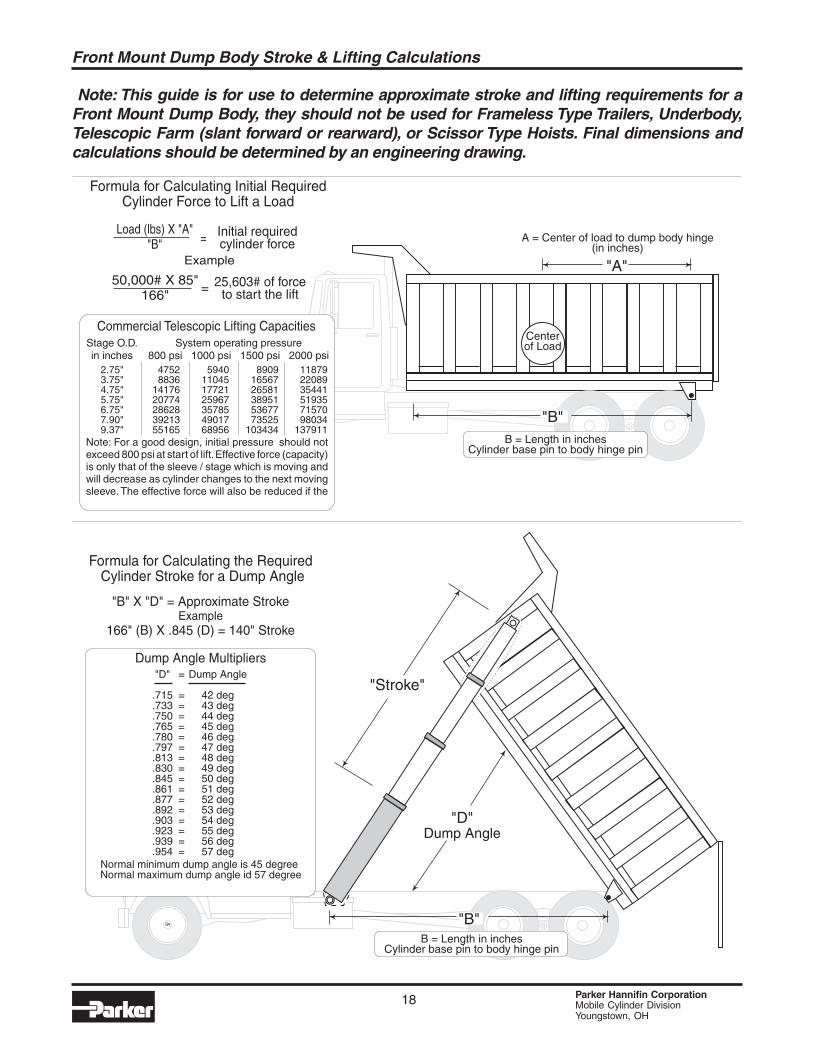
Note: This guide is for use to determine approximate stroke and lifting requirements for aFront Mount Dump Body, they should not be used for Frameless Type Trailers, Underbody,Telescopic Farm (slant forward or rearward), or Scissor Type Hoists. Final dimensions andcalculations should be determined by an engineering drawing.
Front Mount Dump Body Stroke & Lifting Calculations
B = Length in inchesCylinder base pin to body hinge pin
"B"
"D"Dump Angle
"Stroke"
SR
Formula for Calculating the RequiredCylinder Stroke for a Dump Angle
"B" X "D" = Approximate Stroke
166" (B) X .845 (D) = 140" StrokeExample
Normal minimum dump angle is 45 degreeNormal maximum dump angle id 57 degree
Dump Angle Multipliers"D"
.715
.733
.750
.765
.780
.797
.813
.830
.845
.861
.877
.892
.903
.923
.939
.954
Dump Angle
42 deg43 deg44 deg45 deg46 deg47 deg48 deg49 deg50 deg51 deg52 deg53 deg54 deg55 deg56 deg57 deg
=
================
SRSR
A = Center of load to dump body hinge(in inches)
Centerof Load
"A"
B = Length in inchesCylinder base pin to body hinge pin
"B"
Formula for Calculating Initial RequiredCylinder Force to Lift a Load
Example
50,000# X 85"166" = 25,603# of force
to start the lift
Load (lbs) X "A""B" = Initial required
cylinder force
Commercial Telescopic Lifting CapacitiesStage O.D.in inches
2.75"3.75"4.75"5.75"6.75"7.90"9.37"
47528836
1417620774286283921355165
5940110451772125967357854901768956
89091656726581389515367773525
103434
118792208935441519357157098034
137911
System operating pressure800 psi 1000 psi 1500 psi 2000 psi
Note: For a good design, initial pressure should notexceed 800 psi at start of lift.Effective force (capacity)is only that of the sleeve / stage which is moving andwill decrease as cylinder changes to the next movingsleeve. The effective force will also be reduced if the
19 Parker Hannifin CorporationMobile Cylinder DivisionYoungstown, OH
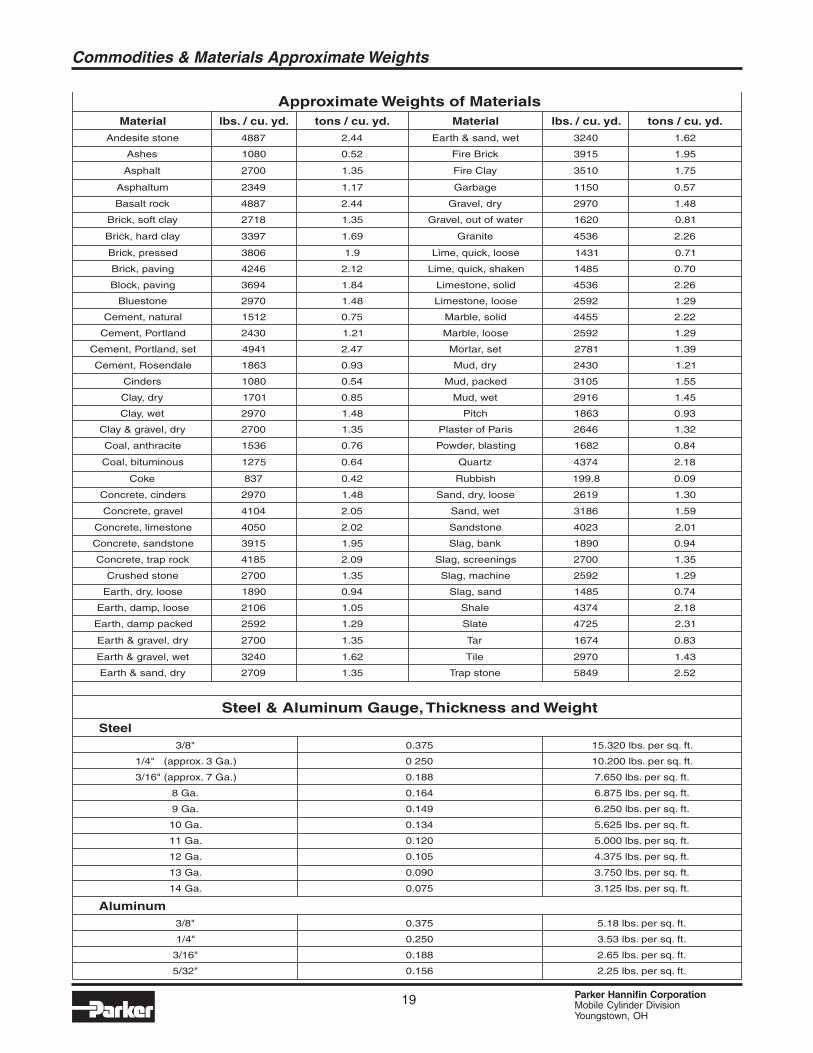
Approximate Weights of MaterialsMaterial lbs. / cu. yd. tons / cu. yd. Material lbs. / cu. yd. tons / cu. yd.
Andesite stone 4887 2.44 Earth & sand, wet 3240 1.62
Ashes 1080 0.52 Fire Brick 3915 1.95
Asphalt 2700 1.35 Fire Clay 3510 1.75
Asphaltum 2349 1.17 Garbage 1150 0.57
Basalt rock 4887 2.44 Gravel, dry 2970 1.48
Brick, soft clay 2718 1.35 Gravel, out of water 1620 0.81
Brick, hard clay 3397 1.69 Granite 4536 2.26
Brick, pressed 3806 1.9 Lime, quick, loose 1431 0.71
Brick, paving 4246 2.12 Lime, quick, shaken 1485 0.70
Block, paving 3694 1.84 Limestone, solid 4536 2.26
Bluestone 2970 1.48 Limestone, loose 2592 1.29
Cement, natural 1512 0.75 Marble, solid 4455 2.22
Cement, Portland 2430 1.21 Marble, loose 2592 1.29
Cement, Portland, set 4941 2.47 Mortar, set 2781 1.39
Cement, Rosendale 1863 0.93 Mud, dry 2430 1.21
Cinders 1080 0.54 Mud, packed 3105 1.55
Clay, dry 1701 0.85 Mud, wet 2916 1.45
Clay, wet 2970 1.48 Pitch 1863 0.93
Clay & gravel, dry 2700 1.35 Plaster of Paris 2646 1.32
Coal, anthracite 1536 0.76 Powder, blasting 1682 0.84
Coal, bituminous 1275 0.64 Quartz 4374 2.18
Coke 837 0.42 Rubbish 199.8 0.09
Concrete, cinders 2970 1.48 Sand, dry, loose 2619 1.30
Concrete, gravel 4104 2.05 Sand, wet 3186 1.59
Concrete, limestone 4050 2.02 Sandstone 4023 2.01
Concrete, sandstone 3915 1.95 Slag, bank 1890 0.94
Concrete, trap rock 4185 2.09 Slag, screenings 2700 1.35
Crushed stone 2700 1.35 Slag, machine 2592 1.29
Earth, dry, loose 1890 0.94 Slag, sand 1485 0.74
Earth, damp, loose 2106 1.05 Shale 4374 2.18
Earth, damp packed 2592 1.29 Slate 4725 2.31
Earth & gravel, dry 2700 1.35 Tar 1674 0.83
Earth & gravel, wet 3240 1.62 Tile 2970 1.43
Earth & sand, dry 2709 1.35 Trap stone 5849 2.52
Steel & Aluminum Gauge,Thickness and WeightSteel
3/8" 0.375 15.320 lbs. per sq. ft.
1/4" (approx. 3 Ga.) 0 250 10.200 lbs. per sq. ft.
3/16" (approx. 7 Ga.) 0.188 7.650 lbs. per sq. ft.
8 Ga. 0.164 6.875 lbs. per sq. ft.
9 Ga. 0.149 6.250 lbs. per sq. ft.
10 Ga. 0.134 5.625 lbs. per sq. ft.
11 Ga. 0.120 5.000 lbs. per sq. ft.
12 Ga. 0.105 4.375 lbs. per sq. ft.
13 Ga. 0.090 3.750 lbs. per sq. ft.
14 Ga. 0.075 3.125 lbs. per sq. ft.
Aluminum3/8" 0.375 5.18 lbs. per sq. ft.
1/4" 0.250 3.53 lbs. per sq. ft.
3/16" 0.188 2.65 lbs. per sq. ft.
5/32" 0.156 2.25 lbs. per sq. ft.
Commodities & Materials Approximate Weights
20 Parker Hannifin CorporationMobile Cylinder DivisionYoungstown, OH
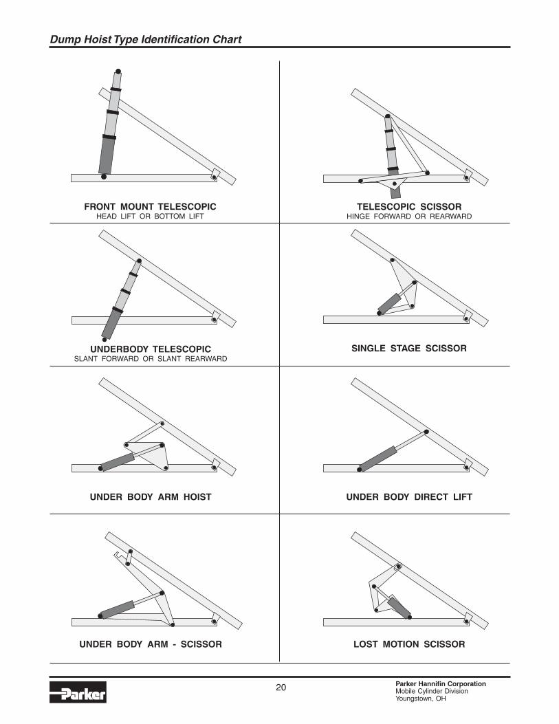
SINGLE STAGE SCISSORUNDERBODY TELESCOPICSLANT FORWARD OR SLANT REARWARD
UNDER BODY ARM HOIST
UNDER BODY ARM - SCISSOR LOST MOTION SCISSOR
UNDER BODY DIRECT LIFT
FRONT MOUNT TELESCOPICHEAD LIFT OR BOTTOM LIFT
TELESCOPIC SCISSORHINGE FORWARD OR REARWARD
Dump Hoist Type Identification Chart
21 Parker Hannifin CorporationMobile Cylinder DivisionYoungstown, OH
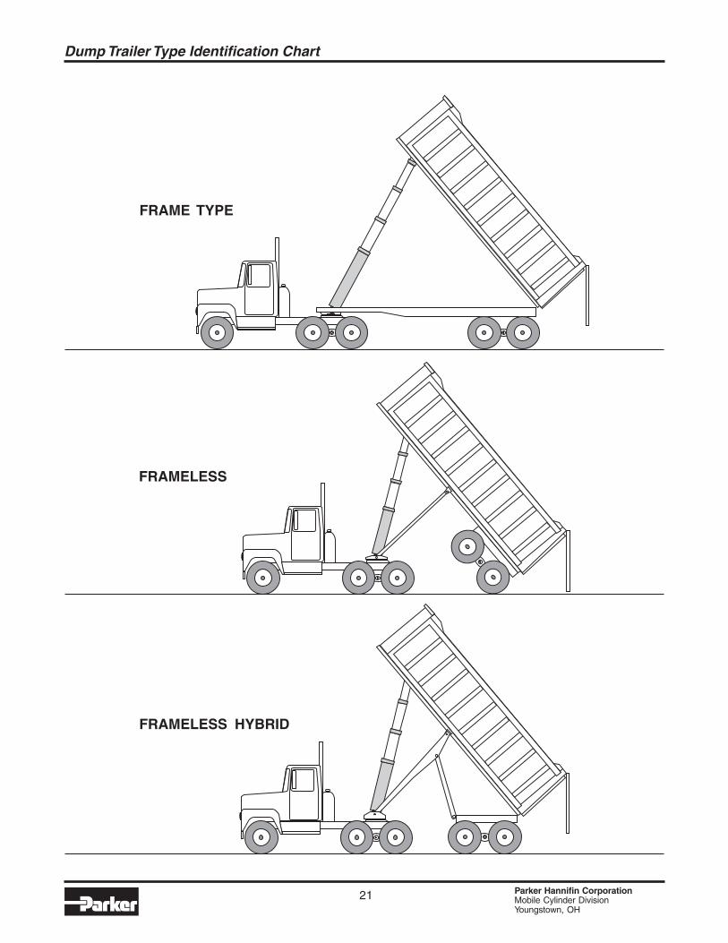
Dump Trailer Type Identification Chart
FRAME TYPE
FRAMELESS
FRAMELESS HYBRID
22 Parker Hannifin CorporationMobile Cylinder DivisionYoungstown, OH
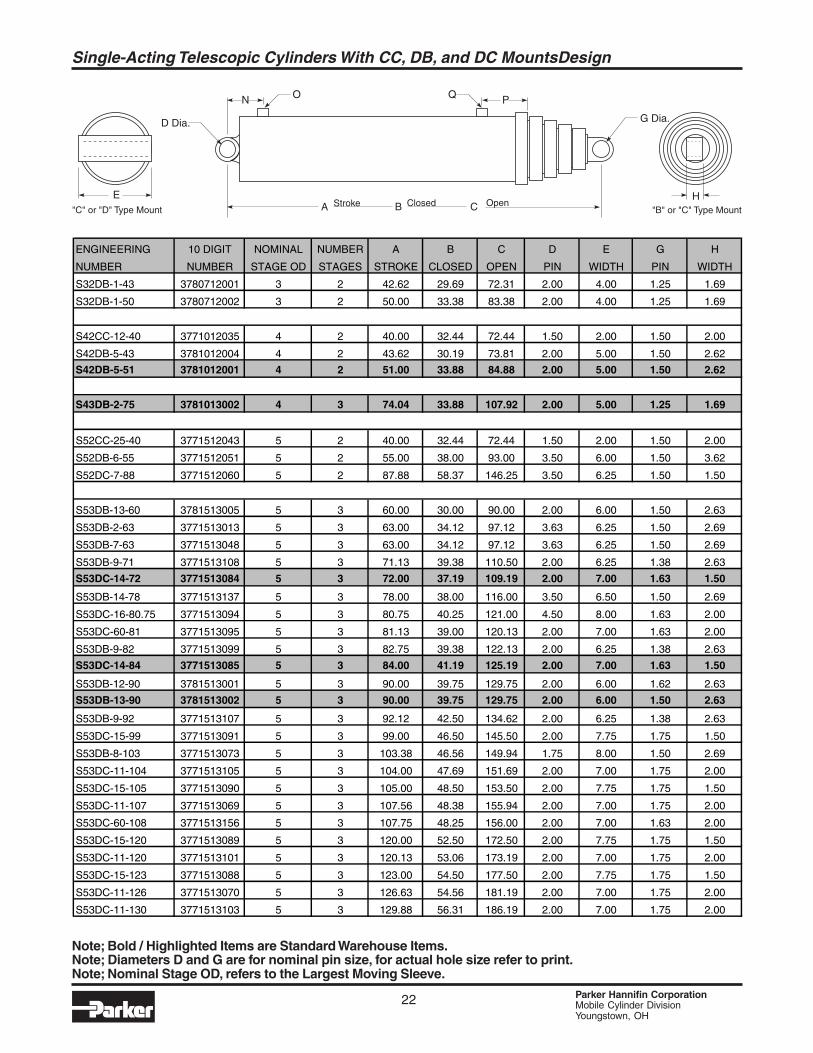
ClosedStroke OpenCBAE
N O PQ
H"B" or "C" Type Mount"C" or "D" Type Mount
G Dia.D Dia.
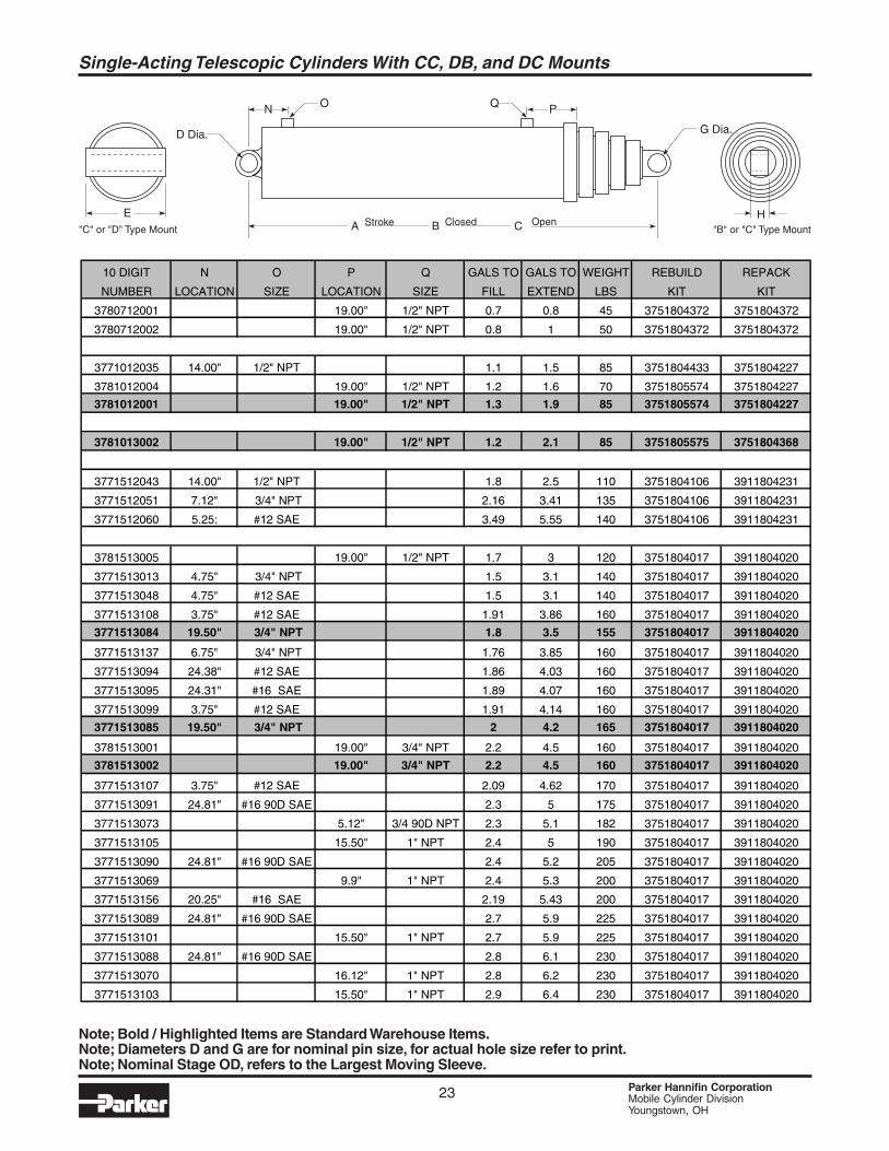
Note; Bold / Highlighted Items are Standard Warehouse Items.Note; Diameters D and G are for nominal pin size, for actual hole size refer to print.Note; Nominal Stage OD, refers to the Largest Moving Sleeve.
ENGINEERING 10 DIGIT NOMINAL NUMBER A B C D E G H
NUMBER NUMBER STAGE OD STAGES STROKE CLOSED OPEN PIN WIDTH PIN WIDTH
S32DB-1-43 3780712001 3 2 42.62 29.69 72.31 2.00 4.00 1.25 1.69
S32DB-1-50 3780712002 3 2 50.00 33.38 83.38 2.00 4.00 1.25 1.69
S42CC-12-40 3771012035 4 2 40.00 32.44 72.44 1.50 2.00 1.50 2.00
S42DB-5-43 3781012004 4 2 43.62 30.19 73.81 2.00 5.00 1.50 2.62
S42DB-5-51 3781012001 4 2 51.00 33.88 84.88 2.00 5.00 1.50 2.62
S43DB-2-75 3781013002 4 3 74.04 33.88 107.92 2.00 5.00 1.25 1.69
S52CC-25-40 3771512043 5 2 40.00 32.44 72.44 1.50 2.00 1.50 2.00
S52DB-6-55 3771512051 5 2 55.00 38.00 93.00 3.50 6.00 1.50 3.62
S52DC-7-88 3771512060 5 2 87.88 58.37 146.25 3.50 6.25 1.50 1.50
S53DB-13-60 3781513005 5 3 60.00 30.00 90.00 2.00 6.00 1.50 2.63
S53DB-2-63 3771513013 5 3 63.00 34.12 97.12 3.63 6.25 1.50 2.69
S53DB-7-63 3771513048 5 3 63.00 34.12 97.12 3.63 6.25 1.50 2.69
S53DB-9-71 3771513108 5 3 71.13 39.38 110.50 2.00 6.25 1.38 2.63
S53DC-14-72 3771513084 5 3 72.00 37.19 109.19 2.00 7.00 1.63 1.50
S53DB-14-78 3771513137 5 3 78.00 38.00 116.00 3.50 6.50 1.50 2.69
S53DC-16-80.75 3771513094 5 3 80.75 40.25 121.00 4.50 8.00 1.63 2.00
S53DC-60-81 3771513095 5 3 81.13 39.00 120.13 2.00 7.00 1.63 2.00
S53DB-9-82 3771513099 5 3 82.75 39.38 122.13 2.00 6.25 1.38 2.63
S53DC-14-84 3771513085 5 3 84.00 41.19 125.19 2.00 7.00 1.63 1.50
S53DB-12-90 3781513001 5 3 90.00 39.75 129.75 2.00 6.00 1.62 2.63
S53DB-13-90 3781513002 5 3 90.00 39.75 129.75 2.00 6.00 1.50 2.63
S53DB-9-92 3771513107 5 3 92.12 42.50 134.62 2.00 6.25 1.38 2.63
S53DC-15-99 3771513091 5 3 99.00 46.50 145.50 2.00 7.75 1.75 1.50
S53DB-8-103 3771513073 5 3 103.38 46.56 149.94 1.75 8.00 1.50 2.69
S53DC-11-104 3771513105 5 3 104.00 47.69 151.69 2.00 7.00 1.75 2.00
S53DC-15-105 3771513090 5 3 105.00 48.50 153.50 2.00 7.75 1.75 1.50
S53DC-11-107 3771513069 5 3 107.56 48.38 155.94 2.00 7.00 1.75 2.00
S53DC-60-108 3771513156 5 3 107.75 48.25 156.00 2.00 7.00 1.63 2.00
S53DC-15-120 3771513089 5 3 120.00 52.50 172.50 2.00 7.75 1.75 1.50
S53DC-11-120 3771513101 5 3 120.13 53.06 173.19 2.00 7.00 1.75 2.00
S53DC-15-123 3771513088 5 3 123.00 54.50 177.50 2.00 7.75 1.75 1.50
S53DC-11-126 3771513070 5 3 126.63 54.56 181.19 2.00 7.00 1.75 2.00
S53DC-11-130 3771513103 5 3 129.88 56.31 186.19 2.00 7.00 1.75 2.00
Single-Acting Telescopic Cylinders With CC, DB, and DC MountsDesign
23 Parker Hannifin CorporationMobile Cylinder DivisionYoungstown, OH
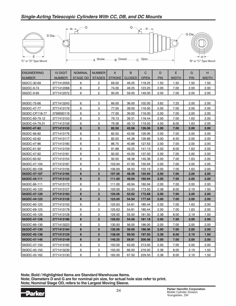
Single-Acting Telescopic Cylinders With CC, DB, and DC Mounts
Note; Bold / Highlighted Items are Standard Warehouse Items.Note; Diameters D and G are for nominal pin size, for actual hole size refer to print.Note; Nominal Stage OD, refers to the Largest Moving Sleeve.
ClosedStroke OpenCBAE
N O PQ
H"B" or "C" Type Mount"C" or "D" Type Mount
G Dia.D Dia.
10 DIGIT N O P Q GALS TO GALS TO WEIGHT REBUILD REPACK
NUMBER LOCATION SIZE LOCATION SIZE FILL EXTEND LBS KIT KIT
3780712001 19.00" 1/2" NPT 0.7 0.8 45 3751804372 3751804372
3780712002 19.00" 1/2" NPT 0.8 1 50 3751804372 3751804372
3771012035 14.00" 1/2" NPT 1.1 1.5 85 3751804433 3751804227
3781012004 19.00" 1/2" NPT 1.2 1.6 70 3751805574 3751804227
3781012001 19.00" 1/2" NPT 1.3 1.9 85 3751805574 3751804227
3781013002 19.00" 1/2" NPT 1.2 2.1 85 3751805575 3751804368
3771512043 14.00" 1/2" NPT 1.8 2.5 110 3751804106 3911804231
3771512051 7.12" 3/4" NPT 2.16 3.41 135 3751804106 3911804231
3771512060 5.25: #12 SAE 3.49 5.55 140 3751804106 3911804231
3781513005 19.00" 1/2" NPT 1.7 3 120 3751804017 3911804020
3771513013 4.75" 3/4" NPT 1.5 3.1 140 3751804017 3911804020
3771513048 4.75" #12 SAE 1.5 3.1 140 3751804017 3911804020
3771513108 3.75" #12 SAE 1.91 3.86 160 3751804017 3911804020
3771513084 19.50" 3/4" NPT 1.8 3.5 155 3751804017 3911804020
3771513137 6.75" 3/4" NPT 1.76 3.85 160 3751804017 3911804020
3771513094 24.38" #12 SAE 1.86 4.03 160 3751804017 3911804020
3771513095 24.31" #16 SAE 1.89 4.07 160 3751804017 3911804020
3771513099 3.75" #12 SAE 1.91 4.14 160 3751804017 3911804020
3771513085 19.50" 3/4" NPT 2 4.2 165 3751804017 3911804020
3781513001 19.00" 3/4" NPT 2.2 4.5 160 3751804017 3911804020
3781513002 19.00" 3/4" NPT 2.2 4.5 160 3751804017 3911804020
3771513107 3.75" #12 SAE 2.09 4.62 170 3751804017 3911804020
3771513091 24.81" #16 90D SAE 2.3 5 175 3751804017 3911804020
3771513073 5.12" 3/4 90D NPT 2.3 5.1 182 3751804017 3911804020
3771513105 15.50" 1" NPT 2.4 5 190 3751804017 3911804020
3771513090 24.81" #16 90D SAE 2.4 5.2 205 3751804017 3911804020
3771513069 9.9" 1" NPT 2.4 5.3 200 3751804017 3911804020
3771513156 20.25" #16 SAE 2.19 5.43 200 3751804017 3911804020
3771513089 24.81" #16 90D SAE 2.7 5.9 225 3751804017 3911804020
3771513101 15.50" 1" NPT 2.7 5.9 225 3751804017 3911804020
3771513088 24.81" #16 90D SAE 2.8 6.1 230 3751804017 3911804020
3771513070 16.12" 1" NPT 2.8 6.2 230 3751804017 3911804020
3771513103 15.50" 1" NPT 2.9 6.4 230 3751804017 3911804020
24 Parker Hannifin CorporationMobile Cylinder DivisionYoungstown, OH
ClosedStroke OpenCBAE
N O PQ
H"B" or "C" Type Mount"C" or "D" Type Mount
G Dia.D Dia.
Single-Acting Telescopic Cylinders With CC, DB, and DC Mounts
ENGINEERING 10 DIGIT NOMINAL NUMBER A B C D E G H
NUMBER NUMBER STAGE OD STAGES STROKE CLOSED OPEN PIN WIDTH PIN WIDTH
S62CC-30-69 3771412059 6 2 69.00 49.25 118.25 1.50 1.50 1.50 1.50
S62DC-9-74 3771412068 6 2 74.00 49.25 123.25 2.00 7.00 2.00 2.00
S62DC-9-90 3771412072 6 2 90.00 59.00 149.00 2.00 7.00 2.00 2.00
S63DC-75-66 3771413243 6 3 66.00 36.00 102.00 3.62 7.25 2.00 2.00
S63DC-47-77 3771413179 6 3 77.00 39.00 116.00 2.00 7.00 2.00 2.00
S63DC-CP118-77 3799000118 6 3 77.00 39.00 116.00 2.00 7.00 2.00 2.00
S63DC-60-79.12 3771413153 6 3 79.13 39.31 118.44 2.00 7.00 1.63 2.00
S63DC-54-79.31 3771413158 6 3 79.38 40.13 119.50 4.50 8.00 1.63 2.00
S63DC-47-82 3771413133 6 3 82.50 43.56 126.06 2.00 7.00 2.00 2.00
S63DC-66-82 3771413176 6 3 82.50 43.56 126.06 2.00 7.00 2.00 2.00
S63DC-42-82 3771413117 6 3 82.50 44.38 126.88 3.00 6.50 2.00 2.00
S63DC-47-86 3771413180 6 3 86.75 40.88 127.63 2.00 7.00 2.00 2.00
S63DC-61-92 3771413159 6 3 91.88 49.25 141.13 4.50 8.00 1.63 2.00
S63DC-47-92 3771413181 6 3 92.00 45.00 137.00 2.00 7.00 2.00 2.00
S63DC-60-92 3771413154 6 3 92.00 48.38 140.38 2.00 7.00 1.63 2.00
S63DC-47-104 3771413187 6 3 103.94 47.00 150.94 2.00 7.00 2.00 2.00
S63DC-60-106 3771413156 6 3 106.69 48.50 155.19 2.00 7.00 1.63 2.00
S63DC-47-107 3771413185 6 3 107.56 48.38 155.94 2.00 7.00 2.00 2.00
S63DC-44-111 3771413125 6 3 111.00 49.94 160.94 2.00 7.00 2.00 2.00
S63DC-66-111 3771413172 6 3 111.00 49.94 160.94 2.00 7.00 2.00 2.00
S63DC-45-120 3771413127 6 3 120.00 53.50 173.50 2.38 8.00 2.19 1.50
S63DC-47-120 3771413183 6 3 120.06 52.62 172.68 2.00 7.00 2.00 2.00
S63DC-44-123 3771413126 6 3 123.00 54.94 177.94 2.00 7.00 2.00 2.00
S63DC-60-125 3771413155 6 3 125.63 54.81 180.44 2.00 7.00 1.63 2.00
S63DC-69-125 3771413178 6 3 125.63 54.81 180.44 2.00 7.00 1.63 2.00
S63DC-45-126 3771413128 6 3 126.00 55.50 181.50 2.38 8.00 2.19 1.50
S63DC-47-126 3771413186 6 3 126.62 54.56 181.18 2.00 7.00 2.00 2.00
S63DC-66-130 3771413223 6 3 130.00 56.00 186.00 2.00 7.00 2.00 2.00
S63DC-47-130 3771413184 6 3 130.06 56.00 186.06 2.00 7.00 2.00 2.00
S63DC-45-138 3771413129 6 3 138.00 59.50 197.50 2.38 8.00 2.19 1.50
S63DC-47-140 3771413149 6 3 140.25 59.81 200.06 2.00 7.00 2.00 2.00
S63DC-47-150 3771413182 6 3 150.00 63.00 213.00 2.00 7.00 2.00 2.00
S63DC-45-150 3771413239 6 3 150.00 66.00 216.00 2.38 8.00 2.19 1.50
S63DC-45-162 3771413130 6 3 162.00 67.50 229.50 2.38 8.00 2.19 1.50
Note; Bold / Highlighted Items are Standard Warehouse Items.Note; Diameters D and G are for nominal pin size, for actual hole size refer to print.Note; Nominal Stage OD, refers to the Largest Moving Sleeve.
25 Parker Hannifin CorporationMobile Cylinder DivisionYoungstown, OH
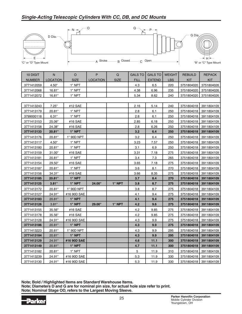
Single-Acting Telescopic Cylinders With CC, DB, and DC Mounts
10 DIGIT N O P Q GALS TO GALS TO WEIGHT REBUILD REPACK
NUMBER LOCATION SIZE LOCATION SIZE FILL EXTEND LBS KIT KIT
3771412059 4.50" 1" NPT 4.3 6.5 220 3751804020 3751804026
3771412068 16.81" 1" NPT 4.38 6.96 235 3751804020 3751804026
3771412072 16.81" 1" NPT 5.34 8.62 240 3751804020 3751804026
3771413243 7.25" #12 SAE 2.16 5.14 240 3751804018 3911804109
3771413179 20.81" 1" NPT 2.8 6.1 250 3751804018 3911804109
3799000118 6.31" 1" NPT 2.8 6.1 250 3751804018 3911804109
3771413153 25.06" #16 SAE 2.85 6.18 250 3751804018 3911804109
3771413158 24.38" #16 SAE 2.8 6.26 250 3751804018 3911804109
3771413133 20.81" 1" NPT 3.2 6.4 250 3751804018 3911804109
3771413176 20.81" 1" 90D NPT 3.2 6.4 250 3751804018 3911804109
3771413117 4.50" 1" NPT 3.23 7.57 250 3751804018 3911804109
3771413180 20.81" 1" NPT 3.1 6.9 250 3751804018 3911804109
3771413159 31.00" #16 SAE 3.31 7.18 275 3751804018 3911804109
3771413181 20.81" 1" NPT 3.4 7.3 265 3751804018 3911804109
3771413154 29.50" #16 SAE 3.65 7.18 275 3751804018 3911804109
3771413187 20.81" 1" NPT 3.6 8.1 270 3751804018 3911804109
3771413156 34.31" #16 SAE 3.66 8.35 275 3751804018 3911804109
3771413185 20.81" 1" NPT 3.7 8.4 270 3751804018 3911804109
3771413125 3.81" 1" NPT 24.00" 1" NPT 3.8 8.7 275 3751804018 3911804109
3771413172 20.81" 1" 90D NPT 3.8 8.7 275 3751804018 3911804109
3771413127 24.91" #16 90D SAE 4.1 9.4 275 3751804018 3911804109
3771413183 20.81" 1" NPT 4.1 9.4 275 3751804018 3911804109
3771413126 3.81" 1" NPT 29.00" 1" NPT 4.2 9.6 275 3751804018 3911804109
3771413155 35.56" #16 SAE 4.2 9.85 275 3751804018 3911804109
3771413178 35.56" #16 SAE 4.2 9.85 275 3751804018 3911804109
3771413128 24.91" #16 90D SAE 4.3 9.9 275 3751804018 3911804109
3771413186 20.81" 1" NPT 4.3 9.9 275 3751804018 3911804109
3771413223 20.81" 1" 90D NPT 4.3 9.9 295 3751804018 3911804109
3771413184 20.81" 1" NPT 4.3 9.9 295 3751804018 3911804109
3771413129 24.91" #16 90D SAE 4.6 11.1 300 3751804018 3911804109
3771413149 20.81" 1" NPT 4.7 11.1 300 3751804018 3911804109
3771413182 20.81" 1" NPT 5 11.9 310 3751804018 3911804109
3771413239 24.91" #16 90D SAE 5.3 11.9 330 3751804018 3911804109
3771413130 24.91" #16 90D SAE 5.3 11.9 330 3751804018 3911804109
ClosedStroke OpenCBAE
N O PQ
H"B" or "C" Type Mount"C" or "D" Type Mount
G Dia.D Dia.
Note; Bold / Highlighted Items are Standard Warehouse Items.Note; Diameters D and G are for nominal pin size, for actual hole size refer to print.Note; Nominal Stage OD, refers to the Largest Moving Sleeve.
26 Parker Hannifin CorporationMobile Cylinder DivisionYoungstown, OH
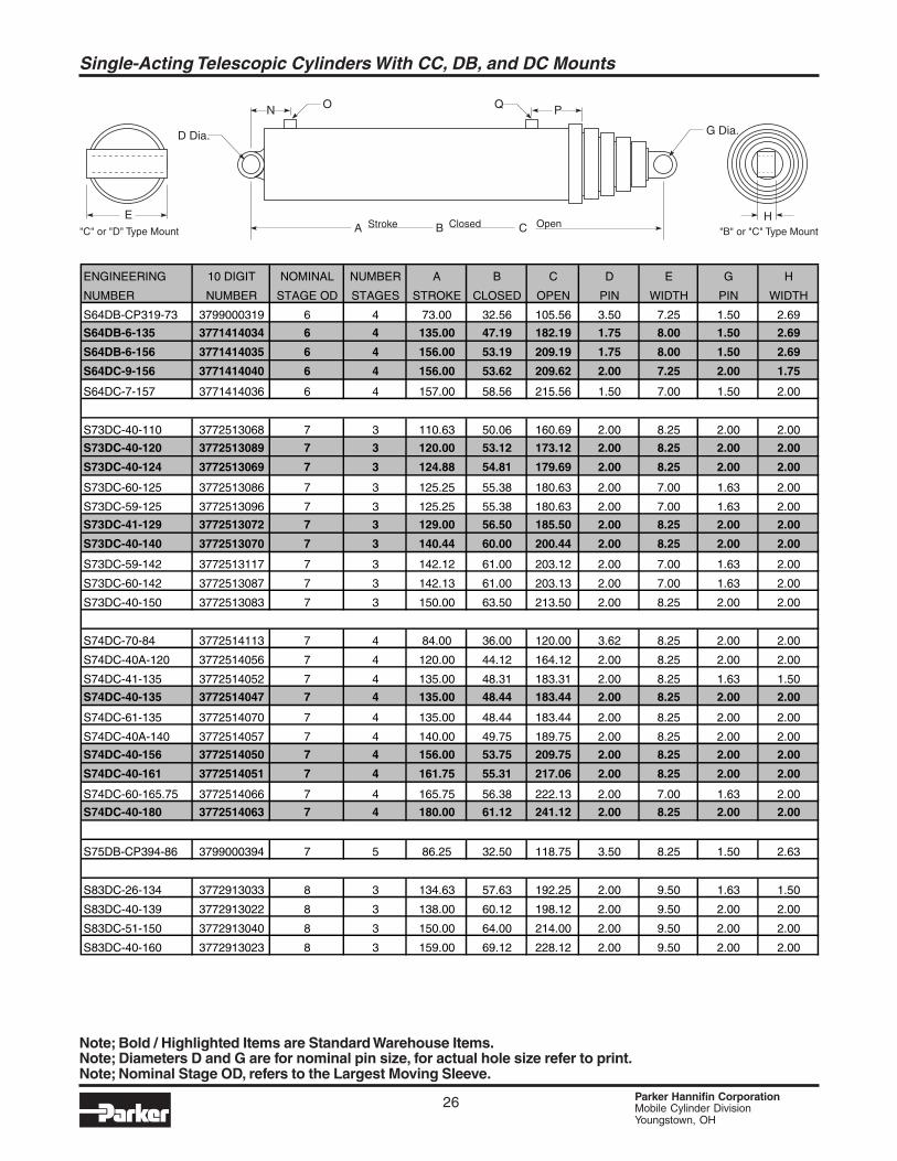
Single-Acting Telescopic Cylinders With CC, DB, and DC Mounts
ENGINEERING 10 DIGIT NOMINAL NUMBER A B C D E G H
NUMBER NUMBER STAGE OD STAGES STROKE CLOSED OPEN PIN WIDTH PIN WIDTH
S64DB-CP319-73 3799000319 6 4 73.00 32.56 105.56 3.50 7.25 1.50 2.69
S64DB-6-135 3771414034 6 4 135.00 47.19 182.19 1.75 8.00 1.50 2.69
S64DB-6-156 3771414035 6 4 156.00 53.19 209.19 1.75 8.00 1.50 2.69
S64DC-9-156 3771414040 6 4 156.00 53.62 209.62 2.00 7.25 2.00 1.75
S64DC-7-157 3771414036 6 4 157.00 58.56 215.56 1.50 7.00 1.50 2.00
S73DC-40-110 3772513068 7 3 110.63 50.06 160.69 2.00 8.25 2.00 2.00
S73DC-40-120 3772513089 7 3 120.00 53.12 173.12 2.00 8.25 2.00 2.00
S73DC-40-124 3772513069 7 3 124.88 54.81 179.69 2.00 8.25 2.00 2.00
S73DC-60-125 3772513086 7 3 125.25 55.38 180.63 2.00 7.00 1.63 2.00
S73DC-59-125 3772513096 7 3 125.25 55.38 180.63 2.00 7.00 1.63 2.00
S73DC-41-129 3772513072 7 3 129.00 56.50 185.50 2.00 8.25 2.00 2.00
S73DC-40-140 3772513070 7 3 140.44 60.00 200.44 2.00 8.25 2.00 2.00
S73DC-59-142 3772513117 7 3 142.12 61.00 203.12 2.00 7.00 1.63 2.00
S73DC-60-142 3772513087 7 3 142.13 61.00 203.13 2.00 7.00 1.63 2.00
S73DC-40-150 3772513083 7 3 150.00 63.50 213.50 2.00 8.25 2.00 2.00
S74DC-70-84 3772514113 7 4 84.00 36.00 120.00 3.62 8.25 2.00 2.00
S74DC-40A-120 3772514056 7 4 120.00 44.12 164.12 2.00 8.25 2.00 2.00
S74DC-41-135 3772514052 7 4 135.00 48.31 183.31 2.00 8.25 1.63 1.50
S74DC-40-135 3772514047 7 4 135.00 48.44 183.44 2.00 8.25 2.00 2.00
S74DC-61-135 3772514070 7 4 135.00 48.44 183.44 2.00 8.25 2.00 2.00
S74DC-40A-140 3772514057 7 4 140.00 49.75 189.75 2.00 8.25 2.00 2.00
S74DC-40-156 3772514050 7 4 156.00 53.75 209.75 2.00 8.25 2.00 2.00
S74DC-40-161 3772514051 7 4 161.75 55.31 217.06 2.00 8.25 2.00 2.00
S74DC-60-165.75 3772514066 7 4 165.75 56.38 222.13 2.00 7.00 1.63 2.00
S74DC-40-180 3772514063 7 4 180.00 61.12 241.12 2.00 8.25 2.00 2.00
S75DB-CP394-86 3799000394 7 5 86.25 32.50 118.75 3.50 8.25 1.50 2.63
S83DC-26-134 3772913033 8 3 134.63 57.63 192.25 2.00 9.50 1.63 1.50
S83DC-40-139 3772913022 8 3 138.00 60.12 198.12 2.00 9.50 2.00 2.00
S83DC-51-150 3772913040 8 3 150.00 64.00 214.00 2.00 9.50 2.00 2.00
S83DC-40-160 3772913023 8 3 159.00 69.12 228.12 2.00 9.50 2.00 2.00
ClosedStroke OpenCBAE
N O PQ
H"B" or "C" Type Mount"C" or "D" Type Mount
G Dia.D Dia.
Note; Bold / Highlighted Items are Standard Warehouse Items.Note; Diameters D and G are for nominal pin size, for actual hole size refer to print.Note; Nominal Stage OD, refers to the Largest Moving Sleeve.
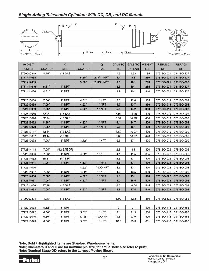
27 Parker Hannifin CorporationMobile Cylinder DivisionYoungstown, OH
Single-Acting Telescopic Cylinders With CC, DB, and DC Mounts
10 DIGIT N O P Q GALS TO GALS TO WEIGHT REBUILD REPACK
NUMBER LOCATION SIZE LOCATION SIZE FILL EXTEND LBS KIT KIT
3799000319 4.75" #12 SAE 1.5 4.63 185 3751804021 3911804237
3771414034 5.50" 2, 3/4" NPT 3.4 8.1 260 3751804021 3911804237
3771414035 5.50" 2, 3/4" NPT 3.5 10.1 293 3751804021 3911804237
3771414040 6.31" 1" NPT 3.5 10.1 285 3751804021 3911804237
3771414036 4.31" 1" NPT 3.9 10.1 310 3751804021 3911804237
3772513068 7.06" 1" NPT 4.62" 1" NPT 5.3 12.6 335 3751804019 3751804002
3772513089 7.06" 1" NPT 4.62" 1" NPT 5.7 13.7 370 3751804019 3751804002
3772513069 7.06" 1" NPT 4.62" 1" NPT 5.9 14.2 380 3751804019 3751804002
3772513086 32.94" #16 SAE 5.94 14.28 400 3751804019 3751804002
3772513096 32.94" #16 SAE 5.94 14.28 400 3751804019 3751804002
3772513072 8.56" 1" NPT 4.62" 1" NPT 6.1 14.7 400 3751804019 3751804002
3772513070 7.06" 1" NPT 4.62" 1" NPT 6.5 16.1 400 3751804019 3751804002
3772513117 43.44" #16 SAE 6.63 16.27 420 3751804019 3751804002
3772513087 43.44" #16 SAE 6.63 16.27 420 3751804019 3751804002
3772513083 7.06" 1" NPT 4.62" 1" NPT 6.5 17.1 425 3751804019 3751804002
3772514113 7.25" #12 SAE OR 2.6 8.1 300 3751804022 3751804003
3772514056 7.06" 1" NPT 4.62" 1" NPT 4.1 11.5 335 3751804022 3751804003
3772514052 18.31" 3/4" NPT 4.5 13.1 370 3751804022 3751804003
3772514047 7.06" 1" NPT 4.62" 1" NPT 4.5 13.1 370 3751804022 3751804003
3772514070 4.62" 1" 90D NPT 4.5 13.1 370 3751804022 3751804003
3772514057 7.06" 1" NPT 4.62" 1" NPT 4.6 13.5 380 3751804022 3751804003
3772514050 7.06" 1" NPT 4.62" 1" NPT 5.1 15.1 390 3751804022 3751804003
3772514051 7.06" 1" NPT 4.62" 1" NPT 5.2 15.5 405 3751804022 3751804003
3772514066 37.19" #16 SAE 6.3 16.04 415 3751804022 3751804003
3772514063 7.06" 1" NPT 4.62" 1" NPT 5.9 17.4 440 3751804022 3751804003
3799000394 4.75" #16 SAE 1.92 6.83 350 3751805472 3751804283
3772913033 5.62" 1" NPT 9 21 520 3751804118 3911804183
3772913022 6.50" 1" NPT 5.62" 1" NPT 9.1 21.9 530 3751804118 3911804183
3772913040 6.50" 1" NPT 17.25" 1" 90D NPT 9.8 23.9 590 3751804118 3911804183
3772913023 6.50" 1" NPT 5.62" 1" NPT 10.6 25.3 601 3751804118 3911804183
ClosedStroke OpenCBAE
N O PQ
H"B" or "C" Type Mount"C" or "D" Type Mount
G Dia.D Dia.
Note; Bold / Highlighted Items are Standard Warehouse Items.Note; Diameters D and G are for nominal pin size, for actual hole size refer to print.Note; Nominal Stage OD, refers to the Largest Moving Sleeve.
28 Parker Hannifin CorporationMobile Cylinder DivisionYoungstown, OH
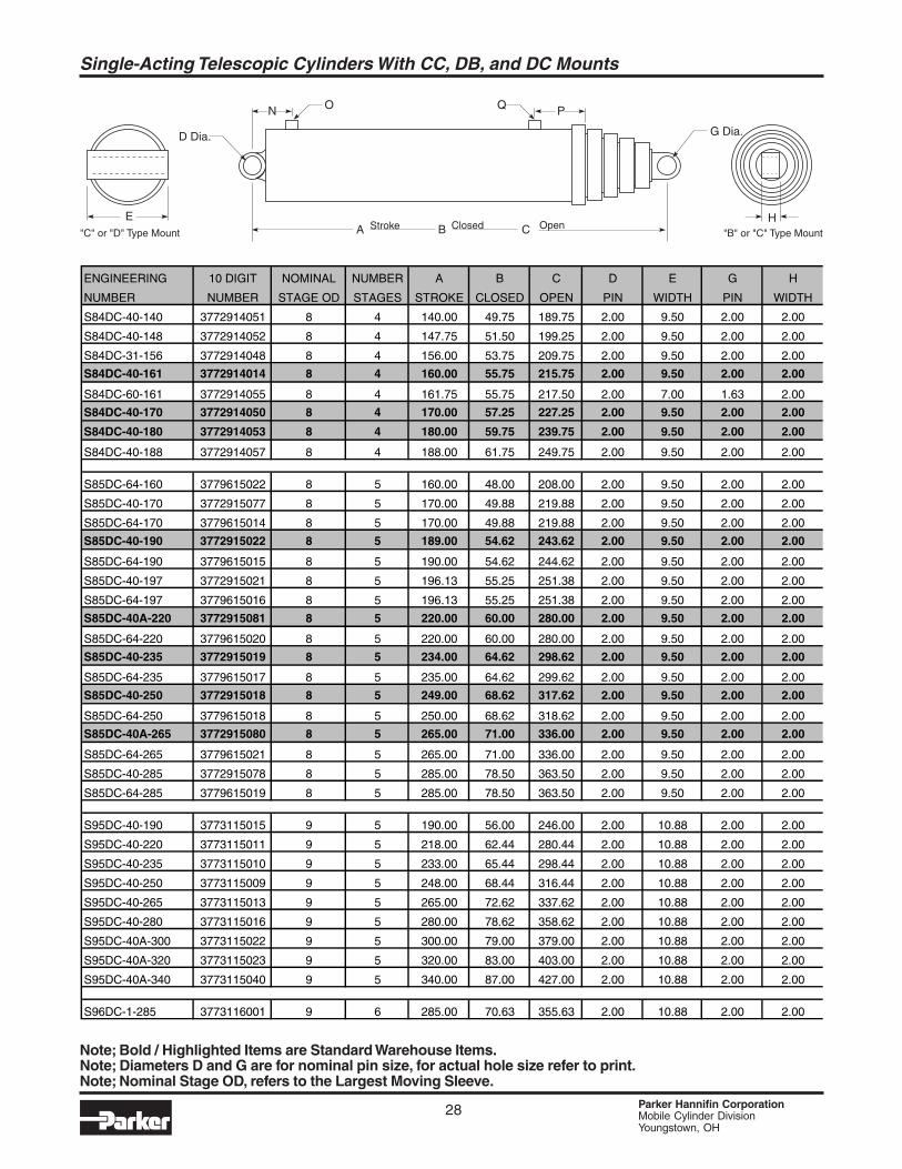
Single-Acting Telescopic Cylinders With CC, DB, and DC Mounts
ENGINEERING 10 DIGIT NOMINAL NUMBER A B C D E G H
NUMBER NUMBER STAGE OD STAGES STROKE CLOSED OPEN PIN WIDTH PIN WIDTH
S84DC-40-140 3772914051 8 4 140.00 49.75 189.75 2.00 9.50 2.00 2.00
S84DC-40-148 3772914052 8 4 147.75 51.50 199.25 2.00 9.50 2.00 2.00
S84DC-31-156 3772914048 8 4 156.00 53.75 209.75 2.00 9.50 2.00 2.00
S84DC-40-161 3772914014 8 4 160.00 55.75 215.75 2.00 9.50 2.00 2.00
S84DC-60-161 3772914055 8 4 161.75 55.75 217.50 2.00 7.00 1.63 2.00
S84DC-40-170 3772914050 8 4 170.00 57.25 227.25 2.00 9.50 2.00 2.00
S84DC-40-180 3772914053 8 4 180.00 59.75 239.75 2.00 9.50 2.00 2.00
S84DC-40-188 3772914057 8 4 188.00 61.75 249.75 2.00 9.50 2.00 2.00
S85DC-64-160 3779615022 8 5 160.00 48.00 208.00 2.00 9.50 2.00 2.00
S85DC-40-170 3772915077 8 5 170.00 49.88 219.88 2.00 9.50 2.00 2.00
S85DC-64-170 3779615014 8 5 170.00 49.88 219.88 2.00 9.50 2.00 2.00
S85DC-40-190 3772915022 8 5 189.00 54.62 243.62 2.00 9.50 2.00 2.00
S85DC-64-190 3779615015 8 5 190.00 54.62 244.62 2.00 9.50 2.00 2.00
S85DC-40-197 3772915021 8 5 196.13 55.25 251.38 2.00 9.50 2.00 2.00
S85DC-64-197 3779615016 8 5 196.13 55.25 251.38 2.00 9.50 2.00 2.00
S85DC-40A-220 3772915081 8 5 220.00 60.00 280.00 2.00 9.50 2.00 2.00
S85DC-64-220 3779615020 8 5 220.00 60.00 280.00 2.00 9.50 2.00 2.00
S85DC-40-235 3772915019 8 5 234.00 64.62 298.62 2.00 9.50 2.00 2.00
S85DC-64-235 3779615017 8 5 235.00 64.62 299.62 2.00 9.50 2.00 2.00
S85DC-40-250 3772915018 8 5 249.00 68.62 317.62 2.00 9.50 2.00 2.00
S85DC-64-250 3779615018 8 5 250.00 68.62 318.62 2.00 9.50 2.00 2.00
S85DC-40A-265 3772915080 8 5 265.00 71.00 336.00 2.00 9.50 2.00 2.00
S85DC-64-265 3779615021 8 5 265.00 71.00 336.00 2.00 9.50 2.00 2.00
S85DC-40-285 3772915078 8 5 285.00 78.50 363.50 2.00 9.50 2.00 2.00
S85DC-64-285 3779615019 8 5 285.00 78.50 363.50 2.00 9.50 2.00 2.00
S95DC-40-190 3773115015 9 5 190.00 56.00 246.00 2.00 10.88 2.00 2.00
S95DC-40-220 3773115011 9 5 218.00 62.44 280.44 2.00 10.88 2.00 2.00
S95DC-40-235 3773115010 9 5 233.00 65.44 298.44 2.00 10.88 2.00 2.00
S95DC-40-250 3773115009 9 5 248.00 68.44 316.44 2.00 10.88 2.00 2.00
S95DC-40-265 3773115013 9 5 265.00 72.62 337.62 2.00 10.88 2.00 2.00
S95DC-40-280 3773115016 9 5 280.00 78.62 358.62 2.00 10.88 2.00 2.00
S95DC-40A-300 3773115022 9 5 300.00 79.00 379.00 2.00 10.88 2.00 2.00
S95DC-40A-320 3773115023 9 5 320.00 83.00 403.00 2.00 10.88 2.00 2.00
S95DC-40A-340 3773115040 9 5 340.00 87.00 427.00 2.00 10.88 2.00 2.00
S96DC-1-285 3773116001 9 6 285.00 70.63 355.63 2.00 10.88 2.00 2.00
ClosedStroke OpenCBAE
N O PQ
H"B" or "C" Type Mount"C" or "D" Type Mount
G Dia.D Dia.
Note; Bold / Highlighted Items are Standard Warehouse Items.Note; Diameters D and G are for nominal pin size, for actual hole size refer to print.Note; Nominal Stage OD, refers to the Largest Moving Sleeve.
29 Parker Hannifin CorporationMobile Cylinder DivisionYoungstown, OH
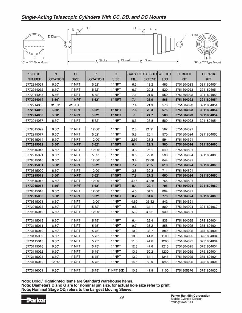
Single-Acting Telescopic Cylinders With CC, DB, and DC Mounts
ClosedStroke OpenCBAE
N O PQ
H"B" or "C" Type Mount"C" or "D" Type Mount
G Dia.D Dia.
10 DIGIT N O P Q GALS TO GALS TO WEIGHT REBUILD REPACK
NUMBER LOCATION SIZE LOCATION SIZE FILL EXTEND LBS KIT KIT
3772914051 6.50" 1" NPT 5.62" 1" NPT 6.5 19.2 485 3751804023 3911804054
3772914052 6.50" 1" NPT 5.62" 1" NPT 6.7 20.3 530 3751804023 3911804054
3772914048 5.56" 1" NPT 5.62" 1" NPT 7.1 21.5 550 3751804023 3911804054
3772914014 6.50" 1" NPT 5.62" 1" NPT 7.4 21.9 565 3751804023 3911804054
3772914055 31.31" #16 SAE 7.4 21.9 570 3751804023 3911804054
3772914050 6.50" 1" NPT 5.62" 1" NPT 7.6 23.3 575 3751804023 3911804054
3772914053 6.50" 1" NPT 5.62" 1" NPT 8 24.7 580 3751804023 3911804054
3772914057 6.50" 1" NPT 5.62" 1" NPT 8.3 25.8 580 3751804023 3911804054
3779615022 6.50" 1" NPT 12.00" 1" NPT 2.8 21.91 567 3751804591
3772915077 6.50" 1" NPT 5.62" 1" NPT 5.8 20.1 570 3751804024 3911804060
3779615014 6.50" 1" NPT 12.00" 1" NPT 2.96 23.3 594 3751804591
3772915022 6.50" 1" NPT 5.62" 1" NPT 6.4 22.3 580 3751804024 3911804060
3779615015 6.50" 1" NPT 12.00" 1" NPT 3.3 26.1 640 3751804591
3772915021 6.50" 1" NPT 5.62" 1" NPT 6.5 22.8 590 3751804024 3911804060
3779615016 6.50" 1" NPT 12.00" 1" NPT 3.4 27.06 644 3751804591
3772915081 6.50" 1" NPT 5.62" 1" NPT 7.2 25.5 610 3751804024 3911804060
3779615020 6.50" 1" NPT 12.00" 1" NPT 3.8 30.3 711 3751804591
3772915019 6.50" 1" NPT 5.62" 1" NPT 7.8 27.2 660 3751804024 3911804060
3779615017 6.50" 1" NPT 12.00" 1" NPT 4.16 32.38 765 3751804591
3772915018 6.50" 1" NPT 5.62" 1" NPT 8.4 29.1 705 3751804024 3911804060
3779615018 6.50" 1" NPT 12.00" 1" NPT 4.5 34.5 804 3751804591
3772915080 6.50" 1" NPT 5.62" 1" NPT 8.7 31.6 776 3751804024 3911804060
3779615021 6.50" 1" NPT 12.00" 1" NPT 4.69 36.52 842 3751804591
3772915078 6.50" 1" NPT 5.62" 1" NPT 9.8 34.1 800 3751804024 3911804060
3779615019 6.50" 1" NPT 12.00" 1" NPT 5.3 39.31 930 3751804591
3773115015 6.50" 1" NPT 5.75" 1" NPT 6.4 22.4 835 3751804025 3751804004
3773115011 6.50" 1" NPT 5.75" 1" NPT 9.7 36.2 855 3751804025 3751804004
3773115010 6.50" 1" NPT 5.75" 1" NPT 10.2 38.7 880 3751804025 3751804004
3773115009 6.50" 1" NPT 5.75" 1" NPT 10.8 41.3 1100 3751804025 3751804004
3773115013 6.50" 1" NPT 5.75" 1" NPT 11.6 44.6 1200 3751804025 3751804004
3773115016 6.50" 1" NPT 5.75" 1" NPT 12.8 47.6 1215 3751804025 3751804004
3773115022 6.50" 1" NPT 5.75" 1" NPT 13.5 50.2 1230 3751804025 3751804004
3773115023 6.50" 1" NPT 5.75" 1" NPT 13.9 54.1 1245 3751804025 3751804004
3773115040 12.50" 1" NPT 5.75" 1" NPT 14.5 59.9 1245 3751804025 3751804004
3773116001 6.50" 1" NPT 5.75" 1" NPT 90D 10.3 41.8 1100 3751805576 3751804030
Note; Bold / Highlighted Items are Standard Warehouse Items.Note; Diameters D and G are for nominal pin size, for actual hole size refer to print.Note; Nominal Stage OD, refers to the Largest Moving Sleeve.
30 Parker Hannifin CorporationMobile Cylinder DivisionYoungstown, OH
ClosedStroke OpenCBA
J
NO
S
KM
L
H"B" or C Type Mount" ""M" Type Mount
G Dia.R
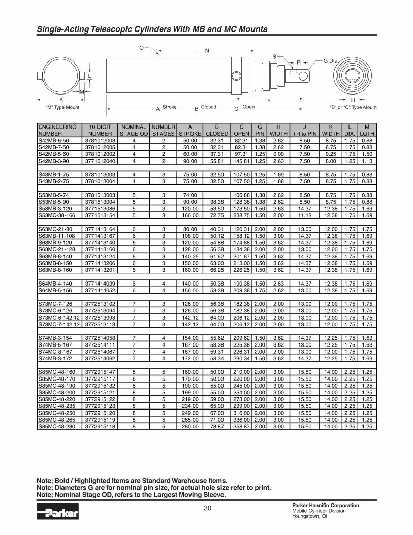
Single-Acting Telescopic Cylinders With MB and MC Mounts
ENGINEERING 10 DIGIT NOMINAL NUMBER A B C G H J K L MNUMBER NUMBER STAGE OD STAGES STROKE CLOSED OPEN PIN WIDTH TR to PIN WIDTH DIA. LGTHS42MB-6-50 3781012003 4 2 50.00 32.31 82.31 1.38 2.62 8.50 8.75 1.75 0.88S42MB-7-50 3781012005 4 2 50.00 32.31 82.31 1.38 2.62 7.50 8.75 1.75 0.88S42MB-5-60 3781012002 4 2 60.00 37.31 97.31 1.25 0.00 7.50 9.25 1.75 1.50S42MB-3-90 3771012040 4 2 90.00 55.81 145.81 1.25 2.63 7.50 8.00 1.25 1.13
S43MB-1-75 3781013003 4 3 75.00 32.50 107.50 1.25 1.69 8.50 8.75 1.75 0.88S43MB-2-75 3781013004 4 3 75.00 32.50 107.50 1.25 1.88 7.50 8.75 1.75 0.88
S53MB-5-74 3781513003 5 3 74.00 106.88 1.38 2.62 8.50 8.75 1.75 0.88S53MB-5-90 3781513004 5 3 90.00 38.38 128.38 1.38 2.62 8.50 8.75 1.75 0.88S53MB-3-120 3771513086 5 3 120.00 53.50 173.50 1.50 2.63 14.37 12.38 1.75 1.69S53MC-38-166 3771513154 5 3 166.00 72.75 238.75 1.50 2.00 11.12 12.38 1.75 1.69
S63MC-21-80 3771413164 6 3 80.00 40.31 120.31 2.00 2.00 13.00 12.00 1.75 1.75S63MB-11-108 3771413167 6 3 108.00 50.12 158.12 1.50 3.00 14.37 12.38 1.75 1.69S63MB-9-120 3771413140 6 3 120.00 54.88 174.88 1.50 3.62 14.37 12.38 1.75 1.69S63MC-21-128 3771413160 6 3 128.00 56.38 184.38 2.00 2.00 13.00 12.00 1.75 1.75S63MB-8-140 3771413124 6 3 140.25 61.62 201.87 1.50 3.62 14.37 12.38 1.75 1.69S63MB-8-150 3771413206 6 3 150.00 63.00 213.00 1.50 3.62 14.37 12.38 1.75 1.69S63MB-8-160 3771413201 6 3 160.00 66.25 226.25 1.50 3.62 14.37 12.38 1.75 1.69
S64MB-4-140 3771414039 6 4 140.00 50.38 190.38 1.50 2.63 14.37 12.38 1.75 1.69S64MB-5-156 3771414052 6 4 156.00 53.38 209.38 1.75 2.62 13.00 12.38 1.75 1.69
S73MC-7-126 3772513102 7 3 126.00 56.38 182.38 2.00 2.00 13.00 12.00 1.75 1.75S73MC-6-126 3772513094 7 3 126.00 56.38 182.38 2.00 2.00 13.00 12.00 1.75 1.75S73MC-6-142.12 3772513093 7 3 142.12 64.00 206.12 2.00 2.00 13.00 12.00 1.75 1.75S73MC-7-142.12 3772513113 7 3 142.12 64.00 206.12 2.00 2.00 13.00 12.00 1.75 1.75
S74MB-3-154 3772514058 7 4 154.00 55.62 209.62 1.50 3.62 14.37 12.25 1.75 1.63S74MB-5-167 3772514111 7 4 167.00 58.38 225.38 2.00 3.62 13.00 12.25 1.75 1.63S74MC-8-167 3772514067 7 4 167.00 59.31 226.31 2.00 2.00 13.00 12.00 1.75 1.75S74MB-3-172 3772514062 7 4 172.00 58.34 230.34 1.50 3.62 14.37 12.25 1.75 1.63
S85MC-48-160 3772915147 8 5 160.00 50.00 210.00 2.00 3.00 15.50 14.00 2.25 1.25S85MC-48-170 3772915117 8 5 170.00 50.00 220.00 2.00 3.00 15.50 14.00 2.25 1.25S85MC-48-190 3772915132 8 5 190.00 55.00 245.00 2.00 3.00 15.50 14.00 2.25 1.25S85MC-48-200 3772915121 8 5 199.00 55.00 254.00 2.00 3.00 15.50 14.00 2.25 1.25S85MC-48-220 3772915122 8 5 219.00 59.00 278.00 2.00 3.00 15.50 14.00 2.25 1.25S85MC-48-235 3772915123 8 5 234.00 65.00 299.00 2.00 3.00 15.50 14.00 2.25 1.25S85MC-48-250 3772915120 8 5 249.00 67.00 316.00 2.00 3.00 15.50 14.00 2.25 1.25S85MC-48-265 3772915119 8 5 265.00 71.00 336.00 2.00 3.00 15.50 14.00 2.25 1.25S85MC-48-280 3772915118 8 5 280.00 78.87 358.87 2.00 3.00 15.50 14.00 2.25 1.25
Note; Bold / Highlighted Items are Standard Warehouse Items.Note; Diameters G are for nominal pin size, for actual hole size refer to print.Note; Nominal Stage OD, refers to the Largest Moving Sleeve.
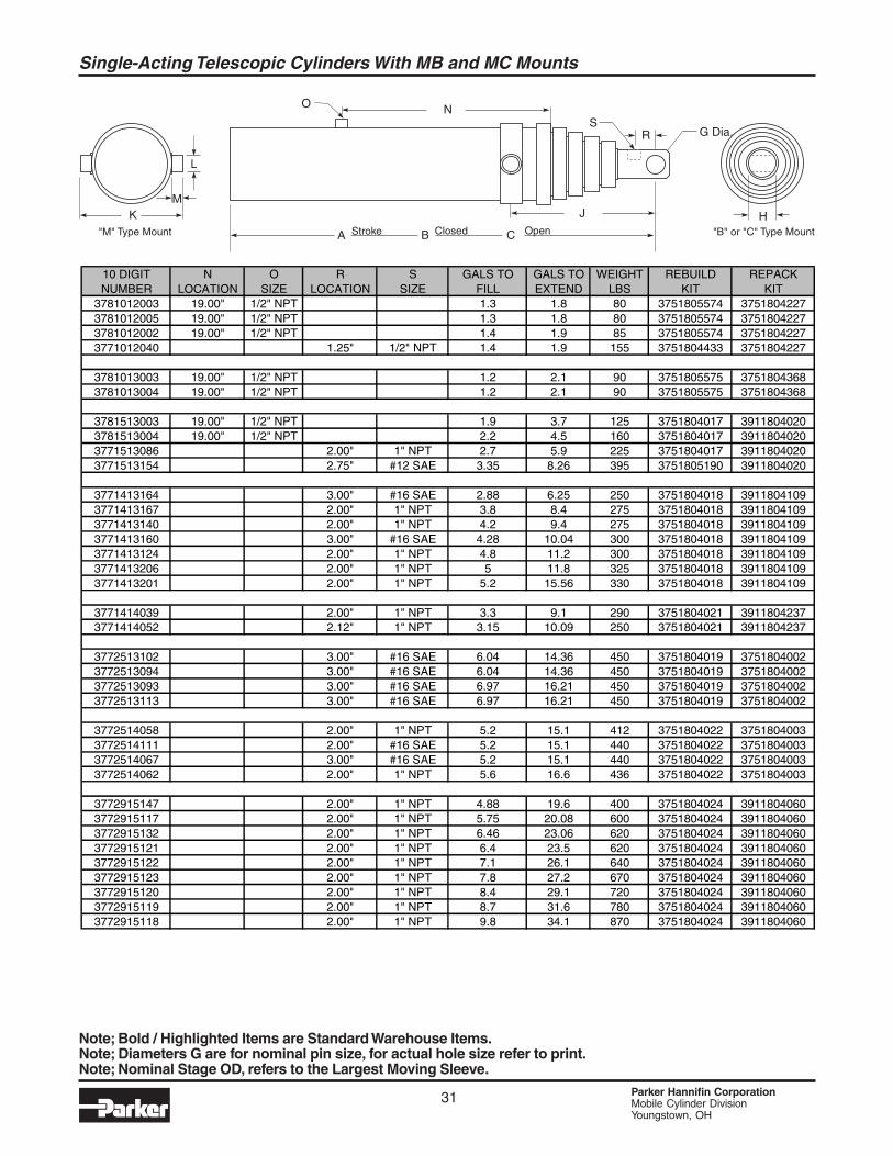
31 Parker Hannifin CorporationMobile Cylinder DivisionYoungstown, OH
Single-Acting Telescopic Cylinders With MB and MC Mounts
ClosedStroke OpenCBA
J
NO
S
KM
L
H"B" or C Type Mount" ""M" Type Mount
G Dia.R
10 DIGIT N O R S GALS TO GALS TO WEIGHT REBUILD REPACKNUMBER LOCATION SIZE LOCATION SIZE FILL EXTEND LBS KIT KIT
3781012003 19.00" 1/2" NPT 1.3 1.8 80 3751805574 37518042273781012005 19.00" 1/2" NPT 1.3 1.8 80 3751805574 37518042273781012002 19.00" 1/2" NPT 1.4 1.9 85 3751805574 37518042273771012040 1.25" 1/2" NPT 1.4 1.9 155 3751804433 3751804227
3781013003 19.00" 1/2" NPT 1.2 2.1 90 3751805575 37518043683781013004 19.00" 1/2" NPT 1.2 2.1 90 3751805575 3751804368
3781513003 19.00" 1/2" NPT 1.9 3.7 125 3751804017 39118040203781513004 19.00" 1/2" NPT 2.2 4.5 160 3751804017 39118040203771513086 2.00" 1" NPT 2.7 5.9 225 3751804017 39118040203771513154 2.75" #12 SAE 3.35 8.26 395 3751805190 3911804020
3771413164 3.00" #16 SAE 2.88 6.25 250 3751804018 39118041093771413167 2.00" 1" NPT 3.8 8.4 275 3751804018 39118041093771413140 2.00" 1" NPT 4.2 9.4 275 3751804018 39118041093771413160 3.00" #16 SAE 4.28 10.04 300 3751804018 39118041093771413124 2.00" 1" NPT 4.8 11.2 300 3751804018 39118041093771413206 2.00" 1" NPT 5 11.8 325 3751804018 39118041093771413201 2.00" 1" NPT 5.2 15.56 330 3751804018 3911804109
3771414039 2.00" 1" NPT 3.3 9.1 290 3751804021 39118042373771414052 2.12" 1" NPT 3.15 10.09 250 3751804021 3911804237
3772513102 3.00" #16 SAE 6.04 14.36 450 3751804019 37518040023772513094 3.00" #16 SAE 6.04 14.36 450 3751804019 37518040023772513093 3.00" #16 SAE 6.97 16.21 450 3751804019 37518040023772513113 3.00" #16 SAE 6.97 16.21 450 3751804019 3751804002
3772514058 2.00" 1" NPT 5.2 15.1 412 3751804022 37518040033772514111 2.00" #16 SAE 5.2 15.1 440 3751804022 37518040033772514067 3.00" #16 SAE 5.2 15.1 440 3751804022 37518040033772514062 2.00" 1" NPT 5.6 16.6 436 3751804022 3751804003
3772915147 2.00" 1" NPT 4.88 19.6 400 3751804024 39118040603772915117 2.00" 1" NPT 5.75 20.08 600 3751804024 39118040603772915132 2.00" 1" NPT 6.46 23.06 620 3751804024 39118040603772915121 2.00" 1" NPT 6.4 23.5 620 3751804024 39118040603772915122 2.00" 1" NPT 7.1 26.1 640 3751804024 39118040603772915123 2.00" 1" NPT 7.8 27.2 670 3751804024 39118040603772915120 2.00" 1" NPT 8.4 29.1 720 3751804024 39118040603772915119 2.00" 1" NPT 8.7 31.6 780 3751804024 39118040603772915118 2.00" 1" NPT 9.8 34.1 870 3751804024 3911804060
Note; Bold / Highlighted Items are Standard Warehouse Items.Note; Diameters G are for nominal pin size, for actual hole size refer to print.Note; Nominal Stage OD, refers to the Largest Moving Sleeve.
32 Parker Hannifin CorporationMobile Cylinder DivisionYoungstown, OH
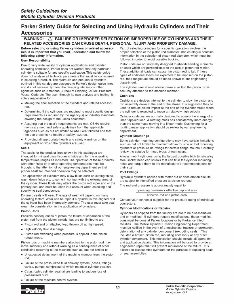
Parker Safety Guide for Selecting and Using Hydraulic Cylinders and TheirAccessories
WARNING: FAILURE OR IMPROPER SELECTION OR IMPROPER USE OF CYLINDERS AND THEIRRELATED ACCESSORIES CAN CAUSE DEATH, PERSONAL INJURY AND PROPERTY DAMAGE.
Before selecting or using Parker cylinders or related accesso-ries, it is important that you read, understand and follow thefollowing safety information.
User Responsibility
Due to very wide variety of cylinder applications and cylinderoperating conditions, Parker does not warrant that any particularcylinder is suitable for any specific application. This safety guidedoes not analyze all technical parameters that must be consideredin selecting a product. The hydraulic and pneumatic cylindersoutlined in this catalog are designed to Parker’s design guide linesand do not necessarily meet the design guide lines of otheragencies such as American Bureau of Shipping, ASME PressureVessel Code etc. The user, through its own analysis and testing, issolely responsible for:
Making the final selection of the cylinders and related accesso-ries.
Determining if the cylinders are required to meet specific designrequirements as required by the Agency(s) or industry standardscovering the design of the user’s equipment.
Assuring that the user’s requirements are met, OSHA require-ments are met, and safety guidelines from the applicableagencies such as but not limited to ANSI are followed and thatthe use presents no health or safety hazards.
Providing all appropriate health and safety warnings on theequipment on which the cylinders are used.
Seals
The seals for the product lines shown in this catalogue areintended for mineral base hydraulic fluids and for the operatingtemperatures ranges as indicated. The operation of these productswith other fluids or at other operating temperatures must bebrought to the attention of our engineering department so thatproper seals for intended operation may be selected.
The application of cylinders may allow fluids such as cutting fluids,wash down fluids etc. to come in contact with the external area ofthe cylinder. These fluids may attack the piston rod wiper and or theprimary seal and must be taken into account when selecting andspecifying seal compounds.
Dynamic seals will wear. The rate of wear will depend on manyoperating factors. Wear can be rapid if a cylinder is mis-aligned or ifthe cylinder has been improperly serviced. The user must take sealwear into consideration in the application of cylinders.
Piston Rods
Possible consequences of piston rod failure or separation of thepiston rod from the piston include, but are not limited to are:
Piston rod and or attached load thrown off at high speed.
High velocity fluid discharge.
Piston rod extending when pressure is applied in the pistonretract mode.
Piston rods or machine members attached to the piston rod maymove suddenly and without warning as a consequence of otherconditions occurring to the machine such as, but not limited to:
Unexpected detachment of the machine member from the pistonrod.
Failure of the pressurized fluid delivery system (hoses, fittings,valves, pumps, compressors) which maintain cylinder position.
Catastrophic cylinder seal failure leading to sudden loss ofpressurized fluid.
Failure of the machine control system.
Part of selecting cylinders for a specific operation involves theproper selection of the piston rod diameter. This catalogue containsinformation in the selection of piston rod diameter, which must befollowed in order to avoid possible buckling.
Piston rods are not normally designed to absorb bending momentsor loads which are perpendicular to the axis of piston rod motion.These additional loads can cause the piston rod to fail. If thesetypes of additional loads are expected to be imposed on the pistonrod, their magnitude should be made known to our engineeringdepartment.
The cylinder user should always make sure that the piston rod issecurely attached to the machine member.
Cushions
Cushions are devices internal to the cylinder to slow the piston androd assembly down at the end of the stroke. It is suggested they beused to reduce piston impact at the end of the cylinder stroke whenthe cylinder is expected to move at relatively high velocity.
Cylinder cushions are normally designed to absorb the energy of alinear applied load. A rotating mass has considerably more energythan the same mass moving in a linear mode. Cushioning for arotating mass application should be review by our engineeringdepartment.
Cylinder Mountings
Some cylinder mounting configurations may have certain limitationssuch as but not limited to minimum stroke for side or foot mountingcylinders or pressure de-ratings for certain flange mounts. Carefullyreview the catalog for these types of restrictions.
Always mount cylinders using the largest possible high tensile alloysteel socket head cap screws that can fit in the cylinder mountingholes and torque them to the manufacturer’s recommendations fortheir size.
Port Fittings
Hydraulic cylinders applied with meter out or deceleration circuitsare subject to intensified pressure at piston rod end.
The rod end pressure is approximately equal to:
operating pressure x effective cap end area
effective rod end piston area
Contact your connector supplier for the pressure rating of individualconnectors.
Cylinder Modifications or Repairs
Cylinders as shipped from the factory are not to be disassembledand or modified. If cylinders require modifications, these modifica-tions must be done at Parker locations or by Parker certifiedfacilities. The Mobile Cylinder Division Engineering Departmentmust be notified in the event of a mechanical fracture or permanentdeformation of any cylinder component (excluding seals). Thisincludes a broken piston rod, mounting accessory or any othercylinder component. This notification should include all operationand application details. This information will be used to provide anengineered repair that will prevent recurrence of the failure. It isallowed to disassemble cylinders for the purpose of replacing sealsor seal assemblies.
Safety Guidelines forMobile Cylinder Division Products
Offer of Sale
The items described in this document are hereby offered for sale at prices to be established by Parker Hannifin Corporation, its subsidiaries and itsauthorized distributors. This offer and its acceptance by any customer (“Buyer”) shall be governed by all of the following Terms and Conditions. Buyer’sorder for any item described in its document, when communicated to Parker Hannifin Corporation, its subsidiary or an authorized distributor (“Seller’]verbally or in writing, shall constitute acceptance of this offer.
1. Terms and Conditions of Sale: All descriptions, quotations, proposals,offers, acknowledgments, acceptances and sales of Seller’s products aresubject to and shall be governed exclusively by the terms and conditionsstated herein. Buyer’s acceptance of any offer to sell is limited to theseterms and conditions. Any terms or conditions in addition to, or inconsistentwith those stated herein, proposed by Buyer in any acceptance of an offerby Seller, are hereby objected to No such additional, different or inconsistentterms and conditions shall become part of the contract between Buyer andSeller unless expressly accepted in writing by Seller. Seller’s acceptance ofany offer to purchase by Buyer is expressly conditional upon Buyer’s assentto all the terms and conditions stated herein, including any terms in additionto, or inconsistent with those contained in Buyer’s offer. Acceptance of Seller’sproducts shall in all events constitute such assent.
2. Payment: Payment shall be made by Buyer net 30 days from the date ofdelivery of the items purchased hereunder. Any claims by Buyer for omissionsor shortages in a shipment shall be waived unless Seller receives noticethereof within 30 days after Buyer’s receipt of the shipment.
3. Delivery: Unless otherwise provided on the face hereof, delivery shall bemade F.O.B. Seller’s plant. Regardless of the method of delivery, however,risk of loss shall pass to Buyer upon Seller’s delivery to a carrier. Any deliverydates shown are approximate only and Seller shall have no liability for anydelays in delivery.
4. Warranty: Seller warrants that the items sold hereunder shall be free fromdefects in material or workmanship for a period of 18 months from the dateof shipment from Parker Hannifin Corporation. THIS WARRANTYCOMPRISES THE SOLE AND ENTIRE WARRANTY PERTAINING TOITEMS PROVIDED HEREUNDER. SELLER MAKES NO OTHERWARRANTY, GUARANTEE, OR REPRESENTATION OF ANY KINDWHATSOEVER. ALL OTHER WARRANTIES, INCLUDING BUT NOTLIMITED TO, MERCHANTIBILITY AND FITNESS FOR PURPOSE,WHETHER EXPRESS, IMPLIED, OR ARISING BY OPERATION OF LAW,TRADE USAGE, OR COURSE OF DEALING ARE HEREBY DISCLAIMED.
NOTWITHSTANDING THE FOREGOING, THERE ARE NO WARRANTIESWHATSOEVER ON ITEMS BUILT OR ACQUIRED WHOLLY OR PARTIALLY,TO BUYER’S DESIGNS OR SPECIFICATIONS.
5. Limitation Of Remedy: SELLER’S LIABILITY ARISING FROM OR IN ANYWAY CONNECTED WITH THE ITEMS SOLD OR THIS CONTRACT SHALLBE LIMITED EXCLUSIVELY TO REPAIR OR REPLACEMENT OF THEITEMS SOLD OR REFUND OF THE PURCHASE PRICE PAID BY BUYER,AT SELLER’S SOLE OPTION. IN NO EVENT SHALL SELLER BE LIABLEFOR ANY INCIDENTAL, CONSEQUENTIAL OR SPECIAL DAMAGES OFANY KIND OR NATURE WHATSOEVER, INCLUDING BUT NOT LIMITEDTO LOST PROFITS ARISING FROM OR IN ANY WAY CONNECTED WITHTHIS AGREEMENT OR ITEMS SOLD HEREUNDER, WHETHER ALLEGEDTO ARISE FROM BREACH OF CONTRACT, EXPRESS OR IMPLIEDWARRANTY, OR IN TORT, INCLUDING WITHOUT LIMITATION,NEGLIGENCE, FAILURE TO WARN OR STRICT LIABILITY.
6. Changes, Reschedules and Cancellations: Buyer may request to modifythe designs or specifications for the items sold hereunder as well as thequantities and delivery dates thereof, or may request to cancel all or part ofthis order, however, no such requested modification or cancellation shallbecome part of the contract between Buyer and Seller unless accepted bySeller in a written amendment to this Agreement. Acceptance of any suchrequested modification or cancellation shall be at Seller’s discretion, andshall be upon such terms and conditions as Seller may require.
7. Special Tooling: A tooling charge may be imposed for any special tooling,including without limitation, dies, fixtures, molds and patterns, acquired tomanufacture items sold pursuant to this contract. Such special tooling shallbe and remain Seller’s property notwithstanding payment of any charges byBuyer. In no event will Buyer acquire any interest in apparatus belonging toSeller which is utilized in the manufacture of the items sold hereunder, evenif such apparatus has been specially converted or adapted for suchmanufacture and notwithstanding any charges paid by Buyer. Unlessotherwise agreed, Seller shall have the right to alter, discard or otherwisedispose of any special tooling or other property in its sole discretion at anytime.
8. Buyer’s Property: Any designs, tools, patterns, materials, drawings,confidential information or equipment furnished by Buyer or any otheritems which become Buyer’s property, may be considered obsolete andmay be destroyed by Seller after two (2) consecutive years have elapsedwithout Buyer placing an order for the items which are manufacturedusing such property. Seller shall not be responsible for any loss or damageto such property while it is in Seller’s possession or control.
9. Taxes: Unless otherwise indicated on the face hereof, all prices andcharges are exclusive of excise, sales, use, property, occupational orlike taxes which may be imposed by any taxing authority upon themanufacture, sale or delivery of the items sold hereunder. If any suchtaxes must be paid by Seller or if Seller is liable for the collection of suchtax, the amount thereof shall be in addition to the amounts for the itemssold. Buyer agrees to pay all such taxes or to reimburse Seller thereforeupon receipt of its invoice. If Buyer claims exemption from any sales, useor other tax imposed by any taxing authority, Buyer shall save Sellerharmless from and against any such tax, together with any interest orpenalties thereon which may be assessed if the items are held to betaxable.
10. Indemnity For Infringement of Intellectual Property Rights: Seller shallhave no liability for infringement of any patents, trademarks, copyrights,trade dress, trade secrets or similar rights except as provided in this Part10. Seller will defend and indemnify Buyer against allegations ofinfringement of U.S. patents, U.S. trademarks, copyrights, trade dressand trade secrets (hereinafter ‘Intellectual Property Rights’). Seller willdefend at its expense and will pay the cost of any settlement or damagesawarded in an action brought against Buyer based on an allegation thatan item sold pursuant to this contract infringes the Intellectual PropertyRights of a third party. Seller’s obligation to defend and indemnify Buyeris contingent on Buyer notifying Seller within ten (10) days after Buyerbecomes aware of such allegations of infringement, and Seller havingsole control over the defense of any allegations or actions including allnegotiations for settlement or compromise. If an item sold hereunder issubject to a claim that it infringes the Intellectual Property Rights of athird party, Seller may, at its sole expense and option, procure for Buyerthe right to continue using said item, replace or modify said item so as tomake it noninfringing, or offer to accept return of said item and return thepurchase price less a reasonable allowance for depreciation.Notwithstanding the foregoing, Seller shall have no liability for claims ofinfringement based on information provided by Buyer, or directed to itemsdelivered hereunder for which the designs are specified in whole or partby Buyer, or infringements resulting from the modification, combinationor use in a system of any item sold hereunder. The foregoing provisionsof this Part 10 shall constitute Seller’s sole and exclusive liability andBuyer’s sole and exclusive remedy for infringement of Intellectual PropertyRights.If a claim is based on information provided by Buyer or if the design foran item delivered hereunder is specified in whole or in part by Buyer,Buyer shall defend and indemnify Seller for all costs, expenses orjudgments resulting from any claim that such item infringes any patent,trademark, copyright, trade dress, trade secret or any similar right.
11. Force Majeure: Seller does not assume the risk of and shall not beliable for delay or failure to perform any of Seller’s obligations by reasonof circumstances beyond the reasonable control of Seller (hereinafter‘events of Force Majeure]. Events of Force Majeure shall include withoutlimitation, accidents, acts of God, strikes or labor disputes, acts, laws,rules or regulations of any government or government agency, fires,floods, delays or failures in delivery of carriers or suppliers, shortages ofmaterials and any other cause beyond Seller’s control.
12. Entire Agreement/Governing Law: The terms and conditions set forthherein, together with any amendments, modifications and any differentterms or conditions expressly accepted by Seller in writing, shall constitutethe entire Agreement concerning the items sold, and there are no oral orother representations or agreements which pertain thereto. ThisAgreement shall be governed in all respects by the law of the State ofOhio. No actions arising out of the sale of the items sold hereunder orthis Agreement may be brought by either party more than two (2) yearsafter the cause of action accrues.
PD4099 9/88

34 Parker Hannifin CorporationMobile Cylinder DivisionYoungstown, OH
Notes
Parker’s CharterTo be a leading worldwide manufacturer of
components and systems for the builders and users ofdurable goods. More specifically, we will design, marketand manufacture products controlling motion, flow andpressure. We will achieve profitable growth throughpremier customer service.
Product InformationNorth American customers seeking product
information, the location of a nearby distributor, or repairservices will receive prompt attention by calling theParker Product Information Center at our toll-freenumber: 1-800-C-PARKER (1-800-272-7537). InEurope, call 00800-C-PARKER-H (00800-2727-5374).
The Fluid Connectors Groupdesigns, manufactures andmarkets rigid and flexibleconnectors, and associatedproducts used in pneumaticand fluid systems.
The Hydraulics Groupdesigns, produces andmarkets a full spectrum ofhydraulic components andsystems to builders and usersof industrial and mobilemachinery andequipment.
The Automation Group is aleading supplier of pneumaticand electromechanicalcomponents and systems toautomation customersworldwide.
The Seal Group designs,manufactures and distributesindustrial and commercialsealing devices and relatedproducts by providingsuperior quality and totalcustomer satisfaction.
The Filtration Groupdesigns, manufactures andmarkets quality filtration andclarification products,providing customers with thebest value, quality, technicalsupport, and globalavailability.
The Instrumentation Groupis a global leader in thedesign, manufacture anddistribution of high-qualitycritical flow components forworldwide processinstrumentation, ultra-high-purity, medical and analyticalapplications.
About Parker Hannifin CorporationParker Hannifin is a leading global motion-control
company dedicated to delivering premier customerservice. A Fortune 500 corporation listed on the NewYork Stock Exchange (PH), our components andsystems comprise over 1,400 product lines that controlmotion in some 1,000 industrial and aerospace markets.Parker is the only manufacturer to offer its customers achoice of hydraulic, pneumatic, and electromechanicalmotion-control solutions. OurCompany has the largest distribution network in its field,with over 7,500 distributors serving nearly 400,000customers worldwide.
Parker Hannifin Corporation6035 Parkland Blvd.Cleveland, Ohio 44124-4141Telephone: (216) 896-3000Fax: (216) 896-4000www.parker.com
Parker Hannifin Corporation
The Aerospace Groupis a leader in thedevelopment, design,manufacture and servicing ofcontrol systems andcomponents for aerospaceand related high-technologymarkets, while achievinggrowth through premiercustomer service.
The Climate & IndustrialControls Groupdesigns, manufactures andmarkets system-control andfluid-handling componentsand systems to refrigeration,air-conditioning and industrialcustomers worldwide.

Mobile Cylinder Div.P.O. Box 239Youngstown, OH 44501-0239Tel: (330) 740-8670Fax: (330) 480-8432www.parker.com
Catalog HY18-0024/US2M, 03/06