hybrid digital–analog source–channel coding for bandwidth compression/expansion
TRANSCRIPT

IEEE TRANSACTIONS ON INFORMATION THEORY, VOL. 52, NO. 8, AUGUST 2006 3757
Hybrid Digital–Analog Source–Channel Coding forBandwidth Compression/Expansion
Mikael Skoglund, Senior Member, IEEE,Nam Phamdo, Senior Member, IEEE, and
Fady Alajaji, Senior Member, IEEE
Abstract—An approach to hybrid digital–analog (HDA) source–channelcoding for the communication of analog sources over memoryless Gaussianchannels is introduced. The HDA system, which exploits the advantages ofboth digital and analog systems, generalizes a scheme previously presentedby the authors, and can operate for any bandwidth ratio (bandwidth com-pression and expansion). It is based on vector quantization and featuresturbo coding in its digital component and linear/nonlinear processing in itsanalog part. Simulations illustrate that, under both bandwidth compres-sion and expansion modes of operation, the HDA system provides a robustand graceful performance with good reproduction fidelity for a wide rangeof channel conditions.
Index Terms—Additive white Gaussian noise (AWGN) channels, broad-casting, Gaussian sources, hybrid digital–analog coding, robust coding,source–channel coding, turbo codes, vector quantization.
I. INTRODUCTION
Consider the problem of constructing a communication system forthe transmission and reproduction of a discrete-time analog-valued(i.e., with continuous alphabet) source over a discrete-time memory-less Gaussian channel. There are two common approaches for buildingsuch a system: analog communication, such as amplitude modulation;and digital communication, which typically consists of quantizing thesource, followed by error-control coding ,and digital modulation.
One of the main advantages of digital communication over analogcommunication is the excellent rate–distortion–capacity performanceoffered by digital coding systems. This excellent performance isachieved by advanced quantization and error-correcting techniques.There are, however, two fundamental disadvantages associated withdigital systems. The first is the “threshold effect” [2], which occurswhen the channel signal-to-noise ratio (CSNR) falls beneath a certainthreshold and the system performance degrades drastically. Thisthreshold effect is due to the total breakdown of the error-correctingcode at low CSNRs and the inherent nonlinearity of the quantizer.During the last two decades, various digital joint source–channelcoding systems have been introduced to fight the threshold effect, thusimproving the system’s error resilience at low CSNRs (see, e.g., thereferences in [3]–[6]). The second disadvantage is the “leveling-offeffect,” which refers to the fact that the system performance remainsconstant even when the CSNR is increased above and beyond the
Manuscript received May 4, 2005; revised April 12, 2006. The work of M.Skoglund was supported in part by the Swedish Research Council (VR) andthe Swedish Governmental Agency for Innovation Systems (VINNOVA). Thework of F. Alajaji was supported in part by the Premier Research ExcellenceAward of Ontario and the Natural Sciences and Engineering Research Councilof Canada. The material in this work was presented in part at the IEEE Interna-tional Symposium on Information Theory, Washington, DC, June 2001.
M. Skoglund is with the School of Electrical Engineering, Royal Institute ofTechnology, SE–100 44 Stockholm, Sweden (e-mail: [email protected]).
N. Phamdo is with the Applied Physics Laboratory, Johns Hopkins Univer-sity, Laurel, MD 20723 USA (email: [email protected]).
F. Alajaji is with the Department of Mathematics and Statistic, and theDepartment of Electrical and Computer Engineering, Queen’s University,Kingston, ON K7L 3N6, Canada (e-mail: [email protected]).
Communicated by S. A. Savari, Associate Editor for Source Coding.Digital Object Identifier 10.1109/TIT.2006.878212
threshold.1 This leveling-off effect is due to the nonrecoverable errorintroduced by the quantizer.
Note that analog systems do not suffer from these problems to thesame extent, in particular concerning the leveling-off effect. On theother hand, in practice, analog systems generally are inferior to dig-ital systems in terms of rate–distortion–capacity performance—partic-ularly at the designed CSNR.
Recently, Mittal and Phamdo [7] proposed a class of hybrid dig-ital–analog (HDA) joint source–channel coding systems. These sys-tems can theoretically achieve the Shannon rate–distortion–capacitylimit at the designed CSNR. Furthermore, they do not suffer from theleveling-off effect—the threshold effect is still inherent, though lesssevere, in the HDA systems [7]. Thus, systems that mix digital andanalog techniques can have some of the advantages of digital systemsand some of the advantages of analog systems (e.g., [3], [6], [8]–[11]).
In [6], [12], we presented a vector quantization (VQ) based HDAsystem. This system is valid only for bandwidth ratios larger than one(bandwidth expansion)—i.e., when the channel bandwidth is greaterthan the source bandwidth. In this correspondence, we introduce a gen-eralized version of the scheme in [6], [12]. The new system, originallyproposed in [1], can be used for either bandwidth expansion or band-width compression. We begin with describing a highly general versionof the system, and then we investigate in some detail the performance,under both bandwidth compression and expansion, of one importanttypical case for the communication of a Gauss–Markov source overa memoryless Gaussian channel. The new scheme has several impor-tant features that were not present in the original work [6], [12]. Inparticular, the system studied in detail incorporates a turbo error-cor-recting code [13] to improve the performance at low CSNRs, and usesa Karhunen–Loéve transform (KLT) to decorrelate the source vector(for the bandwidth compression mode). The new scheme also allowsfor both linear and nonlinear transformations in the analog part of theHDA system (in [6], [12], only linear transformations are used). Otherrecent methods which employ a direct source–channel analog mappingor combine digital and analog coding include those in [3], [8], [11],[14]–[19].
In the next section, we provide a general description of the newHDA system. In Section III, we study in detail the system under band-width compression for a typical scenario and present simulation results.We also compare the performance of the new scheme with i) a purelyanalog system, ii) a purely digital system, and iii) the Shannon rate–dis-tortion–capacity limit. We examine the new system under bandwidthexpansion in Section IV and evaluate its performance vis-a-vis systemsi)–iii) and the scheme studied in [6]. Finally, conclusions are given inSection V.
Some notation used in this correspondence is as follows. Bold-facedcharacters are used for vectors and matrices. Upper case is used forrandom entities and lower case for their realizations. The notation (xxx)mdenotes the mth component of vector xxx.
II. SYSTEM DESCRIPTION
In Fig. 1, we depict a general version of the proposed HDA system.The purpose of the system is to convey the p-dimensional randomsource vector XXX 2
p over a memoryless Gaussian channel, and re-produce it as XXX at the receiver. The upper part of the transmitter is thedigital part, and the lower part the analog part. In the following we de-scribe in detail how the system works.
1In some multimedia applications (such as high-definition television (HDTV)broadcasting), the leveling-off effect may be desirable because large variationsin signal quality over short periods of time may be annoying to the end users.
0018-9448/$20.00 © 2006 IEEE
3758 IEEE TRANSACTIONS ON INFORMATION THEORY, VOL. 52, NO. 8, AUGUST 2006
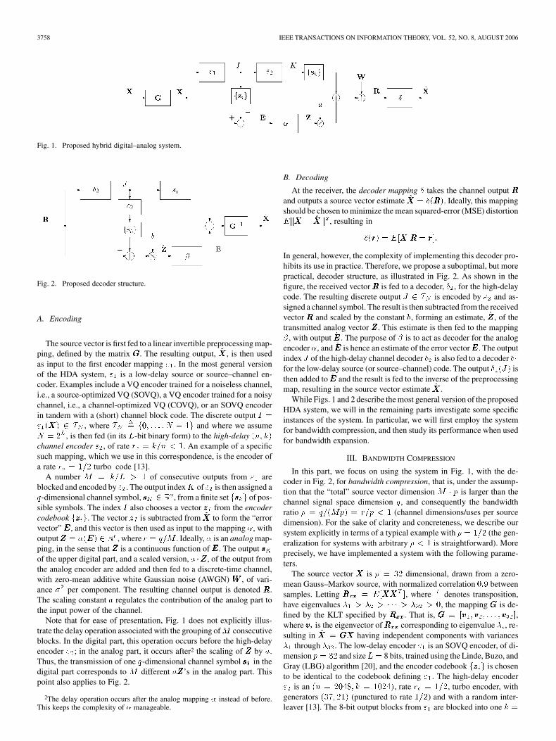
Fig. 1. Proposed hybrid digital–analog system.
Fig. 2. Proposed decoder structure.
A. Encoding
The source vector is first fed to a linear invertible preprocessing map-ping, defined by the matrix GGG. The resulting output, ~XXX , is then usedas input to the first encoder mapping "1. In the most general versionof the HDA system, "1 is a low-delay source or source–channel en-coder. Examples include a VQ encoder trained for a noiseless channel,i.e., a source-optimized VQ (SOVQ), a VQ encoder trained for a noisychannel, i.e., a channel-optimized VQ (COVQ), or an SOVQ encoderin tandem with a (short) channel block code. The discrete output I ="1(XXX) 2 IN , where IN f0; . . . ; N � 1g and where we assumeN = 2L, is then fed (in its L-bit binary form) to the high-delay (n; k)channel encoder "2, of rate rc = k=n < 1. An example of a specificsuch mapping, which we use in this correspondence, is the encoder ofa rate rc = 1=2 turbo code [13].
A number M = k=L > 1 of consecutive outputs from "1 areblocked and encoded by "2. The output indexK of "2 is then assigned aq-dimensional channel symbol, sssK 2 q , from a finite set fssskg of pos-sible symbols. The index I also chooses a vector zzzI from the encodercodebook fzzzig. The vector zzzI is subtracted from ~XXX to form the “errorvector”EEE, and this vector is then used as input to the mapping �, withoutputZZZ = �(EEE) 2 r , where r = q=M . Ideally,� is an analog map-ping, in the sense that ZZZ is a continuous function of EEE. The output sssKof the upper digital part, and a scaled version, a �ZZZ , of the output fromthe analog encoder are added and then fed to a discrete-time channel,with zero-mean additive white Gaussian noise (AWGN) WWW , of vari-ance �2 per component. The resulting channel output is denoted RRR.The scaling constant a regulates the contribution of the analog part tothe input power of the channel.
Note that for ease of presentation, Fig. 1 does not explicitly illus-trate the delay operation associated with the grouping ofM consecutiveblocks. In the digital part, this operation occurs before the high-delayencoder "2; in the analog part, it occurs after2 the scaling of ZZZ by a.Thus, the transmission of one q-dimensional channel symbol sssk in thedigital part corresponds to M different aZZZ’s in the analog part. Thispoint also applies to Fig. 2.
2The delay operation occurs after the analog mapping � instead of before.This keeps the complexity of � manageable.
B. Decoding
At the receiver, the decoder mapping � takes the channel output RRRand outputs a source vector estimate XXX = �(RRR). Ideally, this mappingshould be chosen to minimize the mean squared-error (MSE) distortionEkXXX � XXXk2, resulting in
�(rrr) = E[XXXjRRR = rrr]:
In general, however, the complexity of implementing this decoder pro-hibits its use in practice. Therefore, we propose a suboptimal, but morepractical, decoder structure, as illustrated in Fig. 2. As shown in thefigure, the received vector RRR is fed to a decoder, �2, for the high-delaycode. The resulting discrete output J 2 IN is encoded by "2 and as-signed a channel symbol. The result is then subtracted from the receivedvector RRR and scaled by the constant b, forming an estimate, ZZZ , of thetransmitted analog vector ZZZ . This estimate is then fed to the mapping�, with output EEE. The purpose of � is to act as decoder for the analogencoder�, and EEE is hence an estimate of the error vectorEEE. The outputindex J of the high-delay channel decoder �2 is also fed to a decoder �1for the low-delay source (or source–channel) code. The output �1(J) isthen added to EEE and the result is fed to the inverse of the preprocessingmap, resulting in the source vector estimate XXX .
While Figs. 1 and 2 describe the most general version of the proposedHDA system, we will in the remaining parts investigate some specificinstances of the system. In particular, we will first employ the systemfor bandwidth compression, and then study its performance when usedfor bandwidth expansion.
III. BANDWIDTH COMPRESSION
In this part, we focus on using the system in Fig. 1, with the de-coder in Fig. 2, for bandwidth compression, that is, under the assump-tion that the “total” source vector dimension M � p is larger than thechannel signal space dimension q, and consequently the bandwidthratio � = q=(Mp) = r=p < 1 (channel dimensions/uses per sourcedimension). For the sake of clarity and concreteness, we describe oursystem explicitly in terms of a typical example with � = 1=2 (the gen-eralization for systems with arbitrary � < 1 is straightforward). Moreprecisely, we have implemented a system with the following parame-ters.
The source vector XXX is p = 32 dimensional, drawn from a zero-mean Gauss–Markov source, with normalized correlation 0:9 betweensamples. Letting RRRxxxxxx = E[XXXXXXT ], where T denotes transposition,have eigenvalues �1 > �2 > � � � > �32 > 0, the mapping GGG is de-fined by the KLT specified by RRRxxxxxx. That is, GGG = [vvv1; vvv2; . . . ; vvv32],where vvvi is the eigenvector ofRRRxxxxxx corresponding to eigenvalue �i, re-sulting in ~XXX = GGGXXX having independent components with variances�1 through �32. The low-delay encoder "1 is an SOVQ encoder, of di-mension p = 32 and sizeL = 8 bits, trained using the Linde, Buzo, andGray (LBG) algorithm [20], and the encoder codebook fzzzig is chosento be identical to the codebook defining "1. The high-delay encoder"2 is an (n = 2048; k = 1024), rate rc = 1=2, turbo encoder, withgenerators (37; 21) (punctured to rate 1=2) and with a random inter-leaver [13]. The 8-bit output blocks from "1 are blocked into one k =

IEEE TRANSACTIONS ON INFORMATION THEORY, VOL. 52, NO. 8, AUGUST 2006 3759
1024-bit “superblock” which is fed to "2, resulting in a codeword oflength n = 2048 bits. The output bits from "2, corresponding to theindex K , are mapped directly into binary phase-shift keying (BPSK)symbols,3 with alphabet f�1g. Consequently, the channel signal spacedimension is q = 2048 and sssk 2 f�1g2048. Since M = 1024=8 =128, one "2-codeword represents 128 source vectors, and hence, � =q=(Mp) = 2048=(128 � 32) = 1=2 (channel uses per source dimen-sion).
The scaling constant a, in the analog part, is chosen so that a fraction0 < � < 1 of the total input power to the channel is assigned to theanalog part. That is, since the power in the digital (BPSK) part is 1, theconstant a is solved to satisfy
� =Ma2 EkZZZk2
q +Ma2 EkZZZk2
for a given �. The above equation is based on the assumption that theanalog and digital signals at the channel input are uncorrelated. Exper-imental observations indicate that this is a reasonable assumption. Theoutput ZZZ of the analog encoder has dimension r = q=M = 16 andM = 128 such vectors are transmitted simultaneously with the turboencoder codewords in one superblock.
The high-delay decoder �2 is a turbo decoder for the encoder "2, im-plemented using 10 iterations and given access to the noise variance�2. The low-delay decoder �1 is defined by a table lookup in a code-book identical to the encoder codebook fzzzig. The constant b is chosento minimize the MSE EkZZZ � ZZZk2, under the assumption that �2 ispowerful enough to correct all errors in the digital part and, again, as-suming that �2 is known at the receiver. That is,
b =1
a�
�=(1��)
�2 +�=(1��):
What remains to be specified is the analog encoder–decoder pair(�; �). We have investigated two systems, which are described in thefollowing two subsections. Simulations results for bandwidth compres-sion are then provided in Section III-C.
A. Linear Analog Part
The first system employs linear mappings to define � and �. Moreprecisely, � is the linear mapping that projects EEE onto the subspacespanned by the eigenvectors corresponding to the 16 strongest eigen-values ofRRRxxxxxx. Hence, since a KLT is performed onXXX , the mapping �is simply the operation of dropping the 16 low-energy components ofEEE, resulting in the r = 16 dimensional output ZZZ .
The decoder � is defined by the linear mapping of extending ZZZ from16 to 32 dimensions, by filling in zeros in the 16 low-energy dimen-sions.
B. Nonlinear Analog Part
The second system employs a “discrete approximation” of the op-timal, analog, generally nonlinear mappings (�; �) that minimize theMSE, EkEEE� EEEk2 (so in this case the analog part is not really analog,but “close-to-analog”). The mappings are described as follows.
The components (ZZZ)m; m = 1; . . . ; 16, of ZZZ are constrained tobelong to a discrete set of equally spaced signal points, i.e., multi-level pulse amplitude modulation (PAM). The resolution is 256 PAMlevels per component. Hence, there are 25616 = 2128 different pos-sible values for the transmittedZZZ . The encoder � maps a realization ofEEE into one of these values. Due to the prohibitive encoding complexityof mapping a vectorEEE into one out of 2128 possible values, the encoder
3Although we only treat the case of BPSK signaling in the digital componentof the system, we can clearly accommodate multilevel signaling schemes ingeneral.
Fig. 3. Illustration of a two-dimensional nonlinear analog part implemented forcompression.
is split into 16 different encoders �m; m = 1; . . . ; 16, working inde-pendently on two-dimensional parts of EEE. More precisely
(ZZZ)m = �m (EEE)2m�1; (EEE)2m ; m = 1; . . . ; 16:
Similarly, the decoder is split into 16 independent decoders �m; m =1; . . . ; 16, that each implements hard-decision maximum-likelihood(ML) detection of the transmitted PAM symbol a � (ZZZ)m, based on thereceived value for (ZZZ)m, and then performs a table lookup in a code-book to assign values for (EEE)2m�1 and (EEE)2m. The implementationof the ML detector is based on the assumption that the turbo decoder�2 works without errors.
For each m 2 f1; . . . ; 16g, the encoder �m and decoder �m aretrained to minimize
E (EEE)2m�1 � (EEE)2m�12
+ E (EEE)2m � (EEE)2m2
for a fixed channel noise power �2, a given �, a fixed a and undera constraint on the total transmit power. Note that a power constraintis needed in the design, since even if the PAM constellation for (ZZZ)mand the value of the constant a are fixed, the encoder can still assigndifferent probabilities to different transmitted symbols (note that thePAM symbols have different energy).
In Fig. 3, we illustrate, schematically, the typical structure of thenonlinear compression. The circles mark code vectors in the two-di-mensional input space, and �m is defined by a nearest neighbor searchamong these code vectors to produce the corresponding 256-PAMsymbol. How code vectors are mapped to the PAM alphabet can clearlybe seen in the figure. The two endpoints of the PAM constellation aremapped to the two endpoints of the “spiral” in Fig. 3, and any twoneighboring code vectors correspond to two neighboring PAM points.At the receiver, a nearest neighbor search over the PAM constellationproduces the corresponding code vector (circle in the figure) to give avalue for ((EEE2m�1); (EEE2m)).
The approach we use for the nonlinear analog part, as described, isessentially equivalent to the “BDCE system” studied by Vaishampayanin his Ph.D. dissertation [17] (see, in particular, [17, Secs. 5.4–5.5]). Asimilar system (�; �) has also been investigated in [14]. We refer thereader to [17] for results on optimal encoder and decoder mappings,how to handle the power constraint, and a design algorithm.
3760 IEEE TRANSACTIONS ON INFORMATION THEORY, VOL. 52, NO. 8, AUGUST 2006
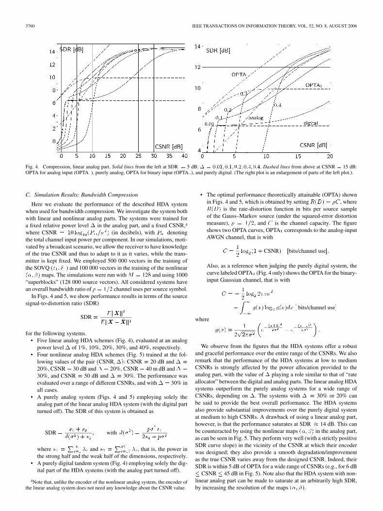
Fig. 4. Compression, linear analog part. Solid lines from the left at SDR = 5 dB: � = 0:01; 0:1;0:2; 0:3; 0:4. Dashed lines from above at CSNR = 15 dB:OPTA for analog input (OPTA ), purely analog, OPTA for binary input (OPTA ), and purely digital. (The right plot is an enlargement of parts of the left plot.).
C. Simulation Results: Bandwidth Compression
Here we evaluate the performance of the described HDA systemwhen used for bandwidth compression. We investigate the system bothwith linear and nonlinear analog parts. The systems were trained fora fixed relative power level � in the analog part, and a fixed CSNR,4
where CSNR = 10 log10(Pin=�
2) (in decibels), with Pin denotingthe total channel input power per component. In our simulations, moti-vated by a broadcast scenario, we allow the receiver to have knowledgeof the true CSNR and thus to adapt to it as it varies, while the trans-mitter is kept fixed. We employed 500 000 vectors in the training ofthe SOVQ ("1; �1) and 100 000 vectors in the training of the nonlinear(�; �) maps. The simulations were run with M = 128 and using 1000“superblocks” (128 000 source vectors). All considered systems havean overall bandwidth ratio of � = 1=2 channel uses per source symbol.
In Figs. 4 and 5, we show performance results in terms of the sourcesignal-to-distortion ratio (SDR)
SDR =EkXXXk2
EkXXX � XXXk2
for the following systems.• Five linear analog HDA schemes (Fig. 4), evaluated at an analog
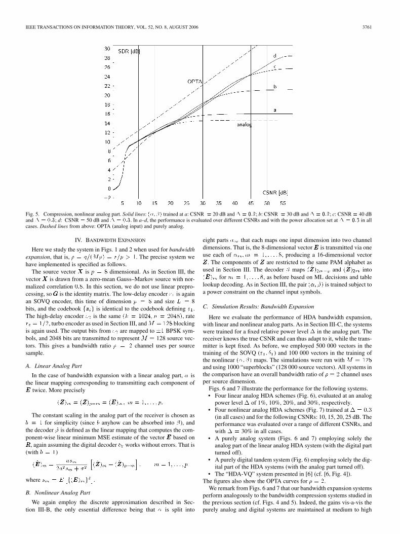
power level � of 1%, 10%, 20%, 30%, and 40%, respectively.• Four nonlinear analog HDA schemes (Fig. 5) trained at the fol-
lowing values of the pair (CSNR;�): CSNR = 20 dB and � =20%, CSNR = 30 dB and � = 20%, CSNR = 40 m dB and � =30%, and CSNR = 50 dB and � = 30%. The performance wasevaluated over a range of different CSNRs, and with � = 30% inall cases.
• A purely analog system (Figs. 4 and 5) employing solely theanalog part of the linear analog HDA system (with the digital partturned off). The SDR of this system is obtained as
SDR =s1 + s2
d(�2) + s2; with d(�2) =
p�2s12s1 + p�2
where s1 = 16
i=1�i and s2 = 32
i=17�i, that is, the power in
the strong half and the weak half of the dimensions, respectively.• A purely digital tandem system (Fig. 4) employing solely the dig-
ital part of the HDA systems (with the analog part turned off).
4Note that, unlike the encoder of the nonlinear analog system, the encoder ofthe linear analog system does not need any knowledge about the CSNR value.
• The optimal performance theoretically attainable (OPTA) shownin Figs. 4 and 5, which is obtained by setting R(D) = �C , whereR(D) is the rate-distortion function in bits per source sampleof the Gauss–Markov source (under the squared-error distortionmeasure), � = 1=2, and C is the channel capacity. The figureshows two OPTA curves, OPTA1 corresponds to the analog-inputAWGN channel, that is with
C =1
2log
2(1 + CSNR) [bits/channel use]:
Also, as a reference when judging the purely digital system, thecurve labeled OPTA2 (Fig. 4 only) shows the OPTA for the binary-input Gaussian channel, that is with
C = � 1
2log
22�e�2
�1
�1
g(x) log2g(x)dx [ bits/channel use]
where
g(x) =1
2p2��2
e�
+ e�
:
We observe from the figures that the HDA systems offer a robustand graceful performance over the entire range of the CSNRs. We alsoremark that the performance of the HDA systems at low to mediumCSNRs is strongly affected by the power allocation provided to theanalog part, with the value of � playing a role similar to that of “rateallocator” between the digital and analog parts. The linear analog HDAsystems outperform the purely analog systems for a wide range ofCSNRs, depending on �. The systems with � = 30% or 20% canbe said to provide the best overall performance. The HDA systemsalso provide substantial improvements over the purely digital systemat medium to high CSNRs. A drawback of using a linear analog part,however, is that the performance saturates at SDR � 14 dB. This canbe counteracted by using the nonlinear maps (�; �) in the analog part,as can be seen in Fig. 5. They perform very well (with a strictly positiveSDR curve slope) in the vicinity of the CSNR at which their encoderwas designed; they also provide a smooth degradation/improvementas the true CSNR varies away from the designed CSNR. Indeed, theirSDR is within 5 dB of OPTA for a wide range of CSNRs (e.g., for 6 dB� CSNR � 45 dB in Fig. 5). Note also that the HDA system with non-linear analog part can be made to saturate at an arbitrarily high SDR,by increasing the resolution of the maps (�; �).
IEEE TRANSACTIONS ON INFORMATION THEORY, VOL. 52, NO. 8, AUGUST 2006 3761
Fig. 5. Compression, nonlinear analog part. Solid lines: (�; �) trained at a: CSNR = 20 dB and � = 0:2; b: CSNR = 30 dB and � = 0:2; c: CSNR = 40 dBand � = 0:3; d: CSNR = 50 dB and � = 0:3. In a–d, the performance is evaluated over different CSNRs and with the power allocation set at � = 0:3 in allcases. Dashed lines from above: OPTA (analog input) and purely analog.
IV. BANDWIDTH EXPANSION
Here we study the system in Figs. 1 and 2 when used for bandwidthexpansion, that is, � = q=(Mp) = r=p > 1. The precise system wehave implemented is specified as follows.
The source vector XXX is p = 8 dimensional. As in Section III, thevector XXX is drawn from a zero-mean Gauss–Markov source with nor-malized correlation 0:8. In this section, we do not use linear prepro-cessing, soGGG is the identity matrix. The low-delay encoder "1 is againan SOVQ encoder, this time of dimension p = 8 and size L = 8bits, and the codebook fzzzig is identical to the codebook defining "1.The high-delay encoder "2 is the same (k = 1024; n = 2048), raterc = 1=2, turbo encoder as used in Section III, andM = 128 blockingis again used. The output bits from "2 are mapped to �1 BPSK sym-bols, and 2048 bits are transmitted to represent M = 128 source vec-tors. This gives a bandwidth ratio � = 2 channel uses per sourcesample.
A. Linear Analog Part
In the case of bandwidth expansion with a linear analog part, � isthe linear mapping corresponding to transmitting each component ofEEE twice. More precisely
(ZZZ)m = (ZZZ)p+m = (EEE)m; m = 1; . . . ; p:
The constant scaling in the analog part of the receiver is chosen asb = 1 for simplicity (since b anyhow can be absorbed into �), andthe decoder � is defined as the linear mapping that computes the com-ponent-wise linear minimum MSE estimate of the vector EEE based onRRR, again assuming the digital decoder �2 works without errors. That is(with b = 1)
(EEE)m =asm
2a2sm + �2(ZZZ)m + (ZZZ)p+m ; m = 1; . . . ; p
where sm = E f(EEE)mg2 .
B. Nonlinear Analog Part
We again employ the discrete approximation described in Sec-tion III-B, the only essential difference being that � is split into
eight parts �m that each maps one input dimension into two channeldimensions. That is, the 8-dimensional vectorEEE is transmitted via oneuse each of �m; m = 1; . . . ; 8, producing a 16-dimensional vectorZZZ . The components of ZZZ are restricted to the same PAM alphabet asused in Section III. The decoder � maps (ZZZ)2m�1 and (ZZZ)2m into(EEE)m for m = 1; . . . ; 8, as before based on ML decisions and tablelookup decoding. As in Section III, the pair (�; �) is trained subject toa power constraint on the channel input symbols.
C. Simulation Results: Bandwidth Expansion
Here we evaluate the performance of HDA bandwidth expansion,with linear and nonlinear analog parts. As in Section III-C, the systemswere trained for a fixed relative power level � in the analog part. Thereceiver knows the true CSNR and can thus adapt to it, while the trans-mitter is kept fixed. As before, we employed 500 000 vectors in thetraining of the SOVQ ("1; �1) and 100 000 vectors in the training ofthe nonlinear (�; �) maps. The simulations were run with M = 128and using 1000 “superblocks” (128 000 source vectors). All systems inthe comparison have an overall bandwidth ratio of � = 2 channel usesper source dimension.
Figs. 6 and 7 illustrate the performance for the following systems.• Four linear analog HDA schemes (Fig. 6), evaluated at an analog
power level � of 1%, 10%, 20%, and 30%, respectively.• Four nonlinear analog HDA schemes (Fig. 7) trained at � = 0:3
(in all cases) and for the following CSNRs: 10, 15, 20, 25 dB. Theperformance was evaluated over a range of different CSNRs, andwith � = 30% in all cases.
• A purely analog system (Figs. 6 and 7) employing solely theanalog part of the linear analog HDA system (with the digital partturned off).
• A purely digital tandem system (Fig. 6) employing solely the dig-ital part of the HDA systems (with the analog part turned off).
• The “HDA-VQ” system presented in [6] (cf. [6, Fig. 4]).The figures also show the OPTA curves for � = 2.
We remark from Figs. 6 and 7 that our bandwidth expansion systemsperform analogously to the bandwidth compression systems studied inthe previous section (cf. Figs. 4 and 5). Indeed, the gains vis-a-vis thepurely analog and digital systems are maintained at medium to high

3762 IEEE TRANSACTIONS ON INFORMATION THEORY, VOL. 52, NO. 8, AUGUST 2006
Fig. 6. Expansion, linear analog part. Solid lines from the left at SDR = 5 dB: � = 0:01; 0:1;0:2; 0:3. Dashed lines from above at CSNR = 9 dB: OPTA foranalog input (OPTA ), OPTA for binary input (OPTA ), the “HDA-VQ” system in [6], purely analog and purely digital.
Fig. 7. Expansion, nonlinear analog part. Solid lines: (�; �) trained at � = 30% and CSNR = 10, 15, 20, 25 dB, as marked. The performance is evaluated overdifferent CSNRs and with the power allocation set at � = 0:3. Dashed lines from above at CSNR = 15 dB: OPTA (analog input), the “HDA-VQ” system in [6],and purely analog.
CSNRs. Furthermore, the HDA system is improved at high CSNRswhen the linear maps in its analog component are replaced by thenonlinear maps. For example, the HDA system with a linear analogpart with � = 30% has an SDR of 28 dB for CSNR = 20 dB (seeFig. 6), while the HDA system with a nonlinear analog part trained forCSNR = 20 dB provides an SDR � 33 dB at the same CSNR (seeFig. 7), resulting in a substantial gain. This gain is however reduced ifthere is a mismatch between the true CSNR and the CSNR for whichthe nonlinear encoder of the analog part is designed; for example, whenthe true CSNR is 20 dB and the nonlinear encoder’s design CSNR is15 dB, the gain is 3 dB (it is 1 dB for a design CSNR of 25 dB). This
indicates that one advantage of the linear analog part is that it does notneed to know the CSNR at the encoder and thus it is not affected by aCSNR mismatch. The main difference between the bandwidth expan-sion and compression systems is that the SDR in our bandwidth ex-pansion schemes, with a linear or infinite-resolution5 nonlinear analogpart, have no leveling-off effect—the slope of their SDR curve is posi-tive for any CSNR. The slope, however, is noticeably less than that ofthe OPTA curve (slope = 2).
5For finite resolution in the proposed implementation of the nonlinear analogpart, the SDR will level off asymptotically, however, in principle, the CSNR atwhich this happens can be pushed arbitrarily high by increasing the resolution.

IEEE TRANSACTIONS ON INFORMATION THEORY, VOL. 52, NO. 8, AUGUST 2006 3763
With respect to the “HDA-VQ” system of [6], it is first worthy topoint out that our system employs superposable coding (as the digitaland analog signals are added to each other at the encoder output be-fore transmission over the channel), while the system of [6] does not.In Fig. 6, we observe that our system with the linear analog part pro-vides a better performance at low to medium CSNRs. This can be ex-plained in virtue of the turbo channel coding employed in the digitalpart of our system, which helps combat channel error in the “water-fall” error region of the turbo code at low to medium CSNRs. On theother hand, the system of [6] does not employ strong channel codingand is hence prone to the significant channel impairment in that CSNRrange. However, in the high-CSNR regime, the system of [6] is less sus-ceptible to channel noise and its analog component becomes “cleaner”than our system’s since it does not use superposable coding; i.e., unlikeour system, it does not need to “filter” out the digital and analog signalsfrom each other at the decoder. Still, as illustrated in Fig. 7, our systemwith the nonlinear analog part can match or outperform the system of[6] at high CSNRs that lie in the vicinity of the CSNR for which thenonlinear encoder map is designed; e.g., the nonlinear system designedfor a CSNR of 25 dB outperforms the scheme of [6] for CSNRs in aninterval starting at 23 dB (for finite resolution in the nonlinear analogpart, the curve from [6] will cross the new curve at a CSNR � 35 dB,however, by increasing the resolution, the range over which the newsystem outperforms the one in [6] can be improved). Finally, it is im-portant to note that the new system is more general than that of [6] as itallows for both expansion and compression modes. In fact, it subsumesthe scheme in [6]; e.g., for � = 2, the new system can be converted tothe one in [6] if we replace the high-delay channel encoding map "2 bya simple rc = 1=2 map resulting in 16 BPSK symbols where the 8 bitsof index I appear in the first eight positions and zeros are stacked inthe last eight positions (the decoder �2 performs the reverse operation),and if we choose the analog map � to produce a vector ZZZ 2
16 suchthat the first eight components ofZZZ are zeros andEEE appears within thelast eight components.
V. SUMMARY AND CONCLUSION
An HDA source–channel coding system for the reliable communi-cation and reproduction of discrete-time analog-valued sources overAWGN channels is proposed and investigated. The HDA system, whichis based on VQ source coding, employs turbo channel coding in its dig-ital component and linear/nonlinear coding in its analog component,before superposing the analog and digital signals for transmission overthe channel. As a result, the system accommodates all bandwidth ratiosand, unlike the scheme studied in [6], it can operate in both bandwidthcompression and expansion modes. Numerical results show that theHDA system provides a robust and graceful performance for a widerange of channel conditions (medium to high CSNRs), substantiallyoutmatching purely digital and analog coding systems. Under band-width compression, the system performs within 5 dB (in SDR) of theOPTA limit for a large CSNR range. The advantages of using linear andnonlinear coding in the analog part of the system are also illustrated:linear coding is simple and does not need the knowledge of the CSNRat the encoder, while nonlinear coding can significantly improve thesystem performance at high CSNRs.
Future work may include improving the system performance at lowCSNRs. An interesting direction is to optimize the performance of thedigital component of the system using joint source–channel codingtechniques without affecting its performance at high CSNRs. Thiscan be accomplished by leaving the VQ encoder unoptimized anddesigning a joint source–channel decoder for the VQ–turbo decoderpair according to the methods of [4], [5], [21]. A first step in thisdirection is undertaken in [22], in the context of image communicationwithout the use of turbo coding, and the digital encoder and decoder
are optimized under bandwidth compression. Finally, since the HDAsystem is general, it can be applied for a variety of source and channelmodels, including fading channels used in conjunction with multilevelmodulation.
REFERENCES
[1] M. Skoglund, N. Phamdo, and F. Alajaji, “Hybrid digital–analogcoding for bandwidth compression/expansion using VQ and turbocodes,” in Proc. IEEE Int. Symp. Information Theory, Washington,DC, Jun. 2001, p. 260.
[2] C. E. Shannon, “Communication in the presence of noise,” Proc. IRE,vol. 37, no. 1, pp. 10–21, Jan. 1949.
[3] H. Coward, “Joint source–channel coding: Development of methodsand utilization in image communications,” Ph.D. dissertation, Norwe-gian Univ. Sci. Technol., Trondheim, Norway, 2001.
[4] N. Phamdo and F. Alajaji, “Soft-decision demodulation design forCOVQ over white, colored and ISI Gaussian channels,” IEEE Trans.Commun., vol. 48, no. 9, pp. 1499–1506, Sep. 2000.
[5] M. Skoglund and P. Hedelin, “Hadamard-based soft decoding forvector quantization over noisy channels,” IEEE Trans. Inf. Theory,vol. 45, no. 2, pp. 515–532, Mar. 1999.
[6] M. Skoglund, N. Phamdo, and F. Alajaji, “Design and performanceof VQ-based hybrid digital–analog joint source–channel codes,” IEEETrans. Inf. Theory, vol. 48, no. 3, pp. 708–720, Mar. 2002.
[7] U. Mittal and N. Phamdo, “Hybrid digital-analog (HDA) jointsource–channel codes for broadcasting and robust communications,”IEEE Trans. Inf. Theory, vol. 48, no. 3, pp. 1082–1102, May 2002.
[8] J. M. Lervik, A. Grovlen, and T. Ramstad, “Robust digital signal com-pression and modulation exploiting the advantages of analog communi-cations,” in Proc. IEEE Global Telecommunications Conf., Singapore,Nov. 1995, pp. 1044–1048.
[9] H. Coward and T. A. Ramstad, “Quantizer optimization in hybrid dig-ital–analog transmission of analog source signals,” in Proc. IEEE Int.Conf. Acoustics, Speech and Signal Processing, Istanbul, Turkey, Jun.2000, pp. 2637–2640.
[10] U. Mittal and N. Phamdo, “A joint source–channel speech coder usinghybrid digital–analog (HDA) modulation,” IEEE Trans. Speech andAudio Processing, vol. 10, no. 4, pp. 222–231, May 2002.
[11] S. Shamai (Shitz), S. Verdú, and R. Zamir, “Systematic lossy source/channel coding,” IEEE Trans. Inf. Theory, vol. 44, no. 2, pp. 564–579,Mar. 1998.
[12] M. Skoglund, N. Phamdo, and F. Alajaji, “VQ-based hybrid dig-ital–analog joint source–channel coding,” in Proc. IEEE Int. Symp.Information Theory, Sorrento, Italy, Jun. 2000, p. 403.
[13] C. Berrou and A. Glavieux, “Near optimum error correcting codingand decoding: Turbo-codes,” IEEE Trans. Commun., vol. 44, no. 10,pp. 1261–1271, Oct. 1996.
[14] A. Fuldseth and T. A. Ramstad, “Bandwidth compression for contin-uous amplitude channels based on vector approximation to a contin-uous subset of the source signal space,” in Proc. IEEE Int. Conf. Acous-tics, Speech and Signal Processing, Munich, Germany, Apr. 1997, pp.3093–3096.
[15] I. Kozintsev and K. Ramchandran, “Hybrid compressed–uncom-pressed framework for wireless image transmission,” in Proc. IEEEInt. Conf. Communications, Montréal, QC, Canada, Jun. 1997, pp.77–80.
[16] T. A. Ramstad, “Combined source coding and modulation for mobilemultimedia communication,” in Insights into Mobile Multimedia Com-munications, D. Bull, N. Canagarajah, and A. Nix, Eds. San Diego,CA: Academic , 1999, ch. 26, pp. 415–430.
[17] V. Vaishampayan, “Combined source–channel coding for bandlimitedwaveform channels,” Ph.D. dissertation, Univ. Maryland, College Park,MD, 1989.
[18] V. A. Vaishampayan and S. I. R. Costa, “Curves on a sphere, shift-mapdynamics, and error control for continuous alphabet sources,” IEEETrans. Inf. Theory, vol. 49, no. 7, pp. 1658–1672, Jul. 2003.
[19] S. Sesia, G. Caire, and G. Vivier, “Lossy transmission over slow-fadingAWGN channels: A comparison of progressive, superposition and hy-brid approaches,” in Proc. IEEE Int. Symp. Information Theory, Ade-laide, Australia, Sep. 2005, pp. 224–228.
[20] A. Gersho and R. M. Gray, Vector Quantization and Signal Compres-sion. Dordrecht, The Netherlands: Kluwer Academic, 1992.
[21] G.-C. Zhu and F. Alajaji, “Soft-decision COVQ for turbo-codedAWGN and Rayleigh fading channels,” IEEE Commun. Lett., vol. 5,no. 6, pp. 257–259, Jun. 2001.
[22] Y. Wang, F. Alajaji, and T. Linder, “Design of VQ-based hybrid dig-ital–analog joint source–channel codes for image communication,” inProc. IEEE Data Compression Conf., Snowbird, UT, Mar. 2005, pp.193–202.