hybrid distributed & decentralized secondary control
TRANSCRIPT
0885-8993 (c) 2019 IEEE. Personal use is permitted, but republication/redistribution requires IEEE permission. See http://www.ieee.org/publications_standards/publications/rights/index.html for more information.
This article has been accepted for publication in a future issue of this journal, but has not been fully edited. Content may change prior to final publication. Citation information: DOI 10.1109/TPEL.2019.2951012, IEEETransactions on Power Electronics
Hybrid distributed & decentralized secondarycontrol strategy to attain accurate power sharing and
improved voltage restoration in dc microgridsWaner Wodson A. G. Silva, Student Member, IEEE, Thiago R. Oliveira, Member, IEEE, and
Pedro F. Donoso-Garcia
Abstract—This paper proposes a secondary level controltechnique for dc microgrids, which achieves accurate powersharing through a distributed strategy whilst performing dcbus voltage restoration in a decentralized fashion. In order toattain proper power sharing, each power converter exchanges itsoutput power information with neighboring converters througha low-bandwidth network at defined time intervals. A consensus-based algorithm is employed to process this information andmodify the converter’s droop coefficient, compensating droopmismatches and cable resistances and enabling power sharing.Restoration of the average dc bus voltage is realized locallywith each converter compensating its own output voltage dropthrough an integrator.A comprehensive design procedure andperformance and stability analysis, including communcation lossand substantial time delays are also provided. The strategy hasshown to be robust to some communication failure scenariosand moderate communication delays. The proposed method isevaluated trough PLECS simulation and it is experimentallyvalidated in a 4.5 kW dc microgrid setup.
Index Terms—Dc microgrids, accurate power sharing, voltagerestoration, consensus-based algorithm, droop-control.
I. INTRODUCTION
THE microgrid concept was introduced as a solution forthe integration of multiple power sources and storage
systems into the grid, where those resources are conjugated ina local power system, enabling optimal usage of distributedgeneration, power dispatch and autonomous operation [1],[2]. DC microgrids are a growing subject in this field, sincethey provide simplified power control, due to the lack ofreactive power flow, phase synchronization and ac powerquality issues [3], as well as a more efficient integration withdistributed generation and storage, due to the elimination ofunnecessary power conversion stages [4], [5]. Fig. 1 presentsa typical residential level dc microgrid and its main ele-ments: a Bidirectional Interface Converter (BIC), responsiblefor interconnecting the microgrid and the utility grid at thepoint of common coupling (PCC), a Renewable ResourceInterface Converter (RRC), which interconnects the distributedgeneration to the microgrid main dc bus and an Energy StorageInterface Converter (ESC). ESC is responsible for ensuringthe power balance either in on-grid or in island operation.The backbone of the dc microgrid is a 380V dc bus, whichinterlinks all converters and supplies local dc loads.
Waner Wodson A. G. da Silva is with the Federal University of Itajuba(UNIFEI),Itabira, Brazil, e-mail: [email protected].
Thiago R. Oliveira is with Electronic Engineering Department, FederalUniversity of Minas Gerais (UFMG), Belo Horizonte, Brazil, e-mail: [email protected]
Pedro F. Donoso-Garcia is with the Electronic Engineering Department,Federal University of Minas Gerais (UFMG), Belo Horizonte, Brazil, e-mail:[email protected]
DC bus 380 V
load
ESC
ESC
utility grid
load
power management
controller
220 VrmsRRC
RR
BICutility grid
Fig. 1. Residential dc microgrid
The power management of dc microgrids is usually basedon a hierarchical structure, adapted from ISA-95 standards,which considers three control layers:
• Primary control: this level refers to the local control of thepower converters. It is responsible to ensure power shar-ing and dc bus voltage regulation and stability [2], [4],[5]. The control techniques employed in this layer mostlyconsist of i) centralized control, based on high or lowbandwidth links, in which a central element determinesthe operation mode of all microgrid converters, either bydefining one to be in voltage mode and regulate the dc busvoltage whereas the others operate as current sources, orby defining the current references of each converter in amaster-slave approach [6], [7], [8], [9]; ii) droop-control,a decentralized approach in which each converter voltagereference is dependent on its output power [10]–[12];
• Secondary control: this layer is responsible for compen-sating the errors introduced by the primary control [2];
• Tertiary control: this layer manages the power flowbetween the microgrid and the utility network. It canestablish voltage and current references at the PCCand modify primary control parameters depending oneconomic and environmental data, in order to achieveoptmized operation of the microgrid [2], [13].
Droop control in the primary level provides high reliabilityand flexibility to the microgrid, since proper power sharing

0885-8993 (c) 2019 IEEE. Personal use is permitted, but republication/redistribution requires IEEE permission. See http://www.ieee.org/publications_standards/publications/rights/index.html for more information.
This article has been accepted for publication in a future issue of this journal, but has not been fully edited. Content may change prior to final publication. Citation information: DOI 10.1109/TPEL.2019.2951012, IEEETransactions on Power Electronics
and stable operation of paralleled converters are guaranteedwithout the need for a communication network, which alsointrinsically introduces plug-and-play capability to it. Con-sequently, droop controlled microgrids are the majority ofthe systems described in the current literature. However, theselection of droop coefficients introduces a trade-off betweenpower sharing and voltage regulation, which is also stronglyinfluenced by line impedances [10]–[12]. In order to correctpower sharing mismatches and dc bus voltage deviation, thesecondary control level gathers information concerning localmeasurements of each converter, through a communicationlink, and provides means to modify primary level parametersthat will lead to proportional power distribution and a regulatedbus voltage. The secondary layer implementation can be eithercentralized or distributed. The centralized approach presentsreduced reliability due to the existence of a single point offailure (SPoF), hence, the employment of distributed controlschemes becomes a better solution [13]–[15].
Voltage deviation and power sharing corrections are mainlyperformed by adding a voltage shifting term to the droopcontroller of the power converters. In [13], a centralizedcontroller senses the dc bus voltage and determines a voltagecorrection term that is broadcasted to all converters, in orderto compensate the voltage deviation. In [5], [11], [16], [17],distributed control is employed, however, each converter needsto exchange information with every other converter in themicrogrid, in order to be able to calculate the average valuesof the dc bus voltage and load current and then determine theappropriate voltage shifting quantity. Sparse communicationnetwork and consensus-based algorithm are described in [18]–[29], which only require information exchange between neigh-boring converters to converge to proper voltage regulation andpower sharing, thus, improving the robustness of the microgridcontrol to communication failures and enabling the use of lowbandwidth communication (LBC).
In terms of power sharing correction, voltage shifting ap-proaches cannot change the output impedance of the powerconverters, hence, in order to compensate line impedancemismatches, the voltage shifting term must be constantlyupdated. Another possibility is to adjust the droop slope,aiming at mitigating the line impedance influence. Hybridcontrol strategies, which uses voltage shifting for dc busvoltage restoration and droop slope adjustment for powersharing correction, have been proposed in [30]–[32]. In [30],the converters exchange their droop resistance, output currentand output voltage information and each of them computes theaverage value of these three parameters, using it to feed threeseparate compensators that will generate the voltage shiftingaction and adapt the converter droop resistance. The need forone converter to establish a communication with all the othersis a drawback of this approach, since large microgrids candemand costly high bandwidth communication links and largedata processing. In [31], [32], the hybrid structure is achievedthrough sparse communication and cooperative control, whichimproves the expandability of the system and resiliency againstcommunication failures. However, the dc bus voltage deviationcorrection is dependent on a voltage observer structure, whichestimates the dc bus average voltage that will be compensated.
In [33] a decentralized voltage restoration strategy is pro-posed for a hybrid energy storage system composed of onebaterry unit and one supercapacitor unit, both connected by
interfacing converters. In this strategy, the supercapacitor unitonly responds to load variations, while the battery deals withthe load power demand in steady state, therefore the dc linkvoltage is regulated by the battery alone, which allows avoltage shifting compensation to be added to the unit’s voltagedroop control reference and ensures a regulated dc voltage insteady state. However, the behavior of the proposed strategyin a scenario with multiple converters and under the influenceof non negligible line impedances is not fully explored orvalidated. In deed, the simple expansion of this strategy tomultiple paralleled converters will lead to high circulatingcurrents between them, hence a coordinated current sharingstrategy is mandatory, however, no discussions concerning thecriteria to integrate the decentralized voltage restoration actionwith current sharing techniques are provided.
This paper proposes a secondary level strategy which usesdistributed control to promote proportional power sharing anda decentralized voltage shifting action to restore the dc busvoltage. The existence of the power sharing action preventshigh circulating currents to build up between converters insteady state and also compesante the average dc bus voltageerrors introduced by the line impedances. A comprehensivedesign procedure and performance analysis is also provided.In the proposed method, a sparse communication network isemployed where each converter exchanges its output powerinformation with its neighbors through a LBC and uses thereceived data to tune its droop coefficient, compensating lineimpedance mismatches and leading to proportional powersharing. Once the power sharing correction is achieved, eachconverter employs only local information to generate a voltageshifting term, which mitigates the dc bus voltage deviationintroduced by the droop control. This strategy reduces theinformation traffic and improves system reliability. Moreover,voltage restoration has shown to be more robust, being dis-turbed only by changes in the equivalent line impedances,i.e., if load variations do not alter the line impedances seenby the converters, voltage regulation is ensured even duringsevere communication failures. It also has shown to providesmall voltage oscillations under fairly high communicationdelays, as confirmed by simulation results. Table I offers acomparison between features of secondary control structuresfound in literature and the proposed strategy.
This work is outlined as follows: Section II analyzes powerand current sharing problems in dc microgrids. Section IIIpresents the proposed secondary level control technique. Sec-tion IV analyzes the influence of the proposed technique onthe system voltage stability. Section V and VI present thesimulation and experimental results, respectively, and SectionVII shows the paper conclusions.
II. DISCUSSION ON CURRENT AND POWER SHARINGPROBLEMS IN DC MICROGRIDS
The following discussion will consider the simplified modelof a dc microgrid presented in Fig. 2, which is composedby two converters (Conv-1 and Conv-2), represented by theirsteady state Thevenin equivalent circuit, line resistances (r1and r2) and a resistive load RµG. V ∗o1 and V ∗o2 refer to thenominal reference voltage of Conv-1 and Conv-2, Rd1 andRd2 are the droop coefficients and vµG is the dc bus voltage

0885-8993 (c) 2019 IEEE. Personal use is permitted, but republication/redistribution requires IEEE permission. See http://www.ieee.org/publications_standards/publications/rights/index.html for more information.
This article has been accepted for publication in a future issue of this journal, but has not been fully edited. Content may change prior to final publication. Citation information: DOI 10.1109/TPEL.2019.2951012, IEEETransactions on Power Electronics
TABLE ICOMPARISON OF SECONDARY CONTROLLERS FOR A DC MICROGRID
Literature proposal Shared information Communicationamong converters
Power/currentsharing correction
Voltagerestoration
Lu et al. [4] Voltage, Current All Voltage shifting DistributedDam and Lee [16] Voltage, Power All Voltage shifting DistributedAnand et al. [17] Current All Voltage shifting NoneXu et al. [33] None None None DecentralizedMeng et al. [18], Zhang et al. [21],Chen et al. [22], Mumtaz et al. [25],Pullaguram et al. [26]
Voltage, Current Neighbors Voltage shifting Distributed
Wang et al. [19] Voltage, Compensating term Neighbors Voltage shifting DistributedMoayedi and Davoudi [24] Voltage, Incremental cost Neighbors Voltage shifting DistributedSahoo and Mishra [28] Voltage, Voltage dynamic aver-
aging, CurrentNeighbors Voltage shifting Distributed
Wang et al. [30] Voltage, Droop coefficient, Cur-rent
All droop-adjustment Distributed
Nasirian et al. [31], Zaery et al. [32] Voltage, Current Neighbors droop-adjustment DistributedProposed technique Power Neighbors droop-adjustment Decentralized
vo1
R G
i GRd1
io1
DC bus
Vo1
r1vo2
Rd2
io2
Vo2
r2
Conv-1
Conv-2
* *
v G
Fig. 2. Simplified model of a dc microgrid
The output current and power of the converters are ex-pressed in (1) and (2), respectively.
io1 =V ∗o1 − vµGRd1 + r1
io2 =V ∗o2 − vµGRd2 + r2
(1)
P1 = vµGio1 + r1i2o1
P2 = vµGio2 + r2i2o2
(2)
It can be noticed that if Conv-1 and Conv-2 are equal, i.e.,V ∗o1 = V ∗o2 and Rd1 = Rd2, current (io1 = io2) and powersharing (P1 = P2) can be achieved only if r1 = r2. Incase of r1 6= r2, converter equality will lead to unbalancedoutput current and power. In this case, current sharing canbe achieved if Rd1 6= Rd2 and/or V ∗o1 6= V ∗o2, but con-comitant power sharing would not be possible. Output powerimbalance between converters can be an important issue insome applications, e.g., ESC in island mode operating, wherepower sharing mismatch leads to unequalized State-of-Charge(SoC). Therefore, considering that unequal line resistances willcertainly be present in a real microgrid, ensuring power sharingover current sharing seems to be the right alternative.
From (1), it can be shown that in any circumstance
io1io2
=Rd2 + r2Rd1 + r1
, (3)
whereas (2) can be manipulated into
P1
P2=io1io2
(vµG + r1io1vµG + r2io2
)= mp, (4)
where mp is a desired power ratio between the two converters.Since vµG = RµG(io1 + io2), the current ratio can also bedefined, from (4), as
io1io2
= −a+√b = mi (5)
where mi is the current ratio that enables mp, and
a =(1−mp)
2(1 + r1RµG
)
b = mp
(1 + r2
RµG
1 + r1RµG
)+
[1−mp
2(1 + r1RµG
)
]2If a droop slope correction term (δRdj , j = 1, 2) is added to
the droop coefficient of each converter, it can be shown from(3) that
io1io2
=(Rd2 + δRd2) + r2(Rd1 + δRd1) + r1
(6)
Therefore, there is a combination of δRd1 and δRd2 that en-forces io1/io2 = mi, hence compensating the line impedancemismatch and ensuring proportional power sharing. It is note-worthy that an adequate mi can also be found for genericloads, although in some cases, e.g., Constant Power Loads(CPL), an analytical solution as the one described in (5), whichdoes not rely on converter parameters, might not exist.
III. PROPOSED HYBRID CONTROL METHOD
Fig. 3 shows the proposed control diagram. It is assumedthat the microgrid comprises N converters sharing the maindc bus, where Conv-j (j = 1, 2, ..., N ) communicates witha set of neighboring converters Nj through a LBC link.At initialization of the control algorithm, Conv-j polls eachConv-k and registers its nominal droop coefficient Rdk, wherek ∈ Nj . Afterwards, in each control cycle, determined bythe communication sampling time τLBC , the communication

0885-8993 (c) 2019 IEEE. Personal use is permitted, but republication/redistribution requires IEEE permission. See http://www.ieee.org/publications_standards/publications/rights/index.html for more information.
This article has been accepted for publication in a future issue of this journal, but has not been fully edited. Content may change prior to final publication. Citation information: DOI 10.1109/TPEL.2019.2951012, IEEETransactions on Power Electronics
i*
droop
controller
current loopi
Ci
vsource voj
ioji
Cv
voj
Vo*
ioj
Rdj
Rdj
voj
voltage loop
voltage correction
voj
Power
sharing
correction
primary control ioj Pj
Conv-j
P1Pk
Conv-1 Conv-2 Conv-3
DC bus
LBC #1
P2Pk P3 Pk P4Pk
Conv-4 Conv-5
P5PkP3
LBC #2
Fig. 3. Diagram of the proposed control
link is used to exchange output power information betweenConv-j and Conv-k allowing the j-th converter to compute adroop coefficient correction term (δRdj) as described in (7),where Pj and Pk, are the output power of Conv-j and Conv-k,respectively, and KP is a gain that affects the power sharingcorrection speed.
δRdj(t) = KP
∫Pj
Pj +∑k∈Nj
Pk− 1
1 +∑k∈Nj
RdjRdk
dt(7)
The dynamic analysis of the power sharing strategy willbe addressed later in this section, however, assuming that itreaches convergence, from (7) it can be shown that equilibriumwill lead to proportional power sharing.
The output voltage voj of Conv-j, incorporating the droopcorrection, is expressed as (8). Assuming that the power ratiowas adjusted through δRdj , the droop voltage (Rdjioj) can becancelled by adding a shifting term (δvoj) as expressed in (9),where KV is the voltage speed correction gain.
voj = V ∗o −Rdjioj − δRdjioj (8)
δvoj(t) = KV
∫Rdjioj − δvoj(t)dt (9)
Considering that the dynamic of voltage restoration ismuch slower than that of droop correction, for simplificationpurposes, it is assumed that changes in ioj during samplescan be neglected, thus, the solution of (9) becomes (10).Substituting it in (8) produces (11), which indicates a firstorder behavior for the output voltage correction, with a timeconstant τ = K−1V , hence after a period of 5/KV from the
l
Fig. 4. Control cycle diagram
last load perturbation the average dc bus voltage will convergeto its reference value.
δvoj(t) = Rdjioj(1 + e−KV t) (10)
∀t > 5/KV : voj = V ∗o − δRdjioj (11)
The correction terms δvoj and δRdj of Conv-j are calculatedwithin the intervals τδvo and τδRd, respectively. Since both ac-tions have an influence on the converter output current, in orderto decouple the dynamics between the two correction loops,those intervals can be defined in relation to τLBC as suggestedin (12). Considering that the power sharing dynamic must befaster than that of voltage restoration, δRdj is computed inevery communication cycle, hence, τδvo must be an integermultiple of τLBC greather than or equal to two. It is importantto mention that, since the voltage-shifting term is incrementedby discrete steps defined as ∆δvo = (Rdjioj − δvoj)KV τδvoand that the voltage restoration convergence time is determinedby KV , increasing τδvo value will lead to higher increments inthe voltage-shifting term. Given that, the output power sharingspeed correction gain is assumed to be KP = 1/τδRd and itis also assumed KV = 1/5τδvo.
τδRd = τLBC
τδvo = 2τLBC(12)
Assuming that a communication node can have up to Nmaxconverters, the time for a converter to sample, send andreceive information (∆tss) can be estimated based on the LBCmessage frame. Taking CAN 2.0A as an example, whose frameconsists of 51 control bits and up to 64 bits of data [34], onecan write:
∆tss =51 + 64 + 3
bps(1 + l)Nmax (13)
where bps is bits per second, 3 are the idle bits betweenmessages and l is the expected lost message rate. τLBC isarbitrated as τLBC > 5∆tss to ensure sufficient time forcomputing Rdj and leave the LBC idle to execute othersecondary and/or tertiary control functions. The control cyclediagram is shown in Fig 4.
A. Dynamic analysis of the proposed power sharing strategy
Considering (7) and the dynamic consensus-based algorithmin discrete-time (DCA-DT), which can be represented as [35]:
xj(t+ 1) = xj(t) + ε∑k∈Nj
ajk(xk(t)− xj(t)) (14)
where xj(t) and xj(t+ 1) are the state of agent j at time t, εis the weighting constant for adjusting the DCA-DT dynamicsand ajk is defined according to the communication statusbetween nodes j and k: ajk 6= 0 if the node j and k are

0885-8993 (c) 2019 IEEE. Personal use is permitted, but republication/redistribution requires IEEE permission. See http://www.ieee.org/publications_standards/publications/rights/index.html for more information.
This article has been accepted for publication in a future issue of this journal, but has not been fully edited. Content may change prior to final publication. Citation information: DOI 10.1109/TPEL.2019.2951012, IEEETransactions on Power Electronics
Conv
1
Conv
2
Conv
3
Conv
3
Conv
1
Conv
2
a) b)
broken
1
1 0
0
Fig. 5. Network topology
neighbors, otherwise ajk = 0 [18]. From a system point ofview, (14) can be expressed in vector form [35], [36]:
X(t+ 1) = WX(t) (15)
where X(t) = [x1(t), x2(t), ...xN (t)]T and W is the commu-nication network weighting matrix, defined by [18]:
W = I − εL (16)
L =
∑k∈N1
a1k . . . −a1N...
. . ....
−a1N . . .∑k∈N
aNk
(17)
where I and L are the Identity and Laplacian matrices of thecommunication network, respectively. Hence, the states of allagents will converge to a consensus value [36]:
limt→∞
X(t) = limt→∞
W tX(0) =
(1
N1.1T
)X(0) (18)
where 1 is a vector with all the components equal to one andX(0) are the initials states.
Considering (7) and the communication network topologiesshown in Fig. 5, Fig. 5-a) presents the Laplacian matrix for adaisy chain topology, whereas Fig. 5-b) considers a situationwhere one link is broken. A constant weighting value ε =τLBC/[(N + 1)τp] was adopted, corresponding to power timeconstant and following the ε definition methods discussed in[18], [36].
Considering xj(t) = Rdj + δRdj(t) + rj , assumingδRdj(0) = 0 and using the equations (15)-(18), it is obtained:
limt→∞
X(t) =1
N∑j=1
Rj
(Rd1 . . . 0...
. . ....
0 . . . RdN
[1]W
)X(0)
(19)where [1] = 1.1T . Rewriting xj(t) to δRdj(t) = xj(t)−Rdj−rj and replacing it in X(t) in (19), one obtains:
limt→∞
δRd(t) =(1
N∑j=1
Rj
Rd1 . . . 0...
. . ....
0 . . . RdN
[1]W − [I]
)X(0)
(20)
andN∑j=1
δRdj(t) = 0 (21)
1
1.5
2
2.5
3
x(t
)
Conv-1 Conv-2 Conv-3
0 1 2 3 4 5 6 7
time (s)
-0.6
-0.3
0
0.3
0.6
Rd(t
)
Conv-1 Conv-2 Conv-3
2.74
2.23
1.19
failure of
communication
change r1,
r2 and r
3
start
tp = 1s t
p = 1s
2.19
2.19
1.09
2.42
2.42
1.21tpf
= 2.35s
2.40
2.40
1.20
change r1,
r2 and r
3
Fig. 6. Convergence of δRd(t)
Assuming the simplified dc bus model of Fig. 2, with twoequal converters, hence, Rd1 = Rd2 and r1 6= r2, (20) and(21) results in:
δRd1 = −δRd2 =r2 − r1
2(22)
The average output voltage of the converters is expressedas (23). Substituting (22) in (11) and the result in (23), onecan obtain (24). Since (r2 − r1)/4 1, then voavg ≈ V ∗o .
voavg =vo1 + vo2
2(23)
voavg = V ∗o −r2 − r1
4(io1 − io2) (24)
As an example, consider a dc microgrid with three con-verters in a daisy chain structure, as depicted in Fig. 5-a),where the droop coefficients are chosen so that the powerratio is 0.5:1:1, hence, Rd2 = Rd3 = 2Rd1 = 2Ω, the lineresistances are r1 = 0.19Ω, r2 = 0.23Ω and r3 = 0.74Ω andτLBC = 50ms, τp = 0.2. Note that, since rj Rdj , powerand current ratios are similar. Fig. 6 shows the convergencedynamic of δRd(t) and x(t), under different conditions of themicrogrid. The compensation action starts at t = 0.5s and att = 2s a load modification changes the values of the equivalentline resistances to r1 = 0.1Ω, r2 = 0.12Ω and r3 = 0.26. Inboth circumstances, it can be observed that x(t) convergesto the specified power ratio with the same time interval tp.In t = 3.5s occurs a communication failure between Conv-2 and Conv-3, which does not affect the power ratio, sinceno alteration in line resistances took place during that event.Finally, at t = 4.5s the line impedances change to r1 = 0.1Ω,r2 = 0.1Ω and r3 = 0.9 and once again convergence isachieved, however, it can be observed that if a communicationfailure occurs, the convergence time will be longer. The errorin x(t) decreases exponentially with a rate that is related to theeigenvalues (λ(.)) of matrix L , thus, λ(.) determine the globaldynamics [37]–[39]. In this sense, the broken link Laplacian,shown in Fig.5.b, presents a set of eigenvalues that will resultin a convergence time tpf = 2.35tp, i.e., 2.35 times longerthan the daisy chain communication structure.
B. Time delay on consensus-based algorithm
Dynamic consensus-based algorithm stability can be sen-sitive to time delays. According to [39], [40], consideringuniform communication link delays τjk = τd, the consensus

0885-8993 (c) 2019 IEEE. Personal use is permitted, but republication/redistribution requires IEEE permission. See http://www.ieee.org/publications_standards/publications/rights/index.html for more information.
This article has been accepted for publication in a future issue of this journal, but has not been fully edited. Content may change prior to final publication. Citation information: DOI 10.1109/TPEL.2019.2951012, IEEETransactions on Power Electronics
1
1.5
2
2.5
3
x(t
)
Conv-1 Conv-2 Conv-3
0 1 2 3 4 5 6 7 8 9 10time (s)
-1.4
-0.7
0
0.7
Rd(t
)
Conv-1 Conv-2 Conv-3
2.42
2.42
1.21
2.16
2.16
1.08
td = t
dmax
change r1,
r2 and r
3
change r1,
r2 and r
3
td = t
dmax/2
start
Fig. 7. Convergence of δRd(t) with time delay
algorithm converges if τd < π/2λN , where λN is the largesteigenvalue of the matrix L. Since τd is inversely proportionalto λN , then, conservatively, one can assume τdmax < π/2Nas time delay limit, because λN will be lower than the orderof matrix L. Moreover, for τd = π/2λN the system hasa stable oscillatory solution with frequency ω = λN [39].Therefore, the communication on large networks should becarefully designed to minimize time delays or to increase themaximum tolerable delay time, e.g., reducing the number ofconnections per node.
In order to illustrate the influence that large time delayscan have on the microgrid behavior, the example describedin the previous section was revisited, assuming a time delay(td) between the nodes. Fig. 7 shows the δRd(t) convergenceconsidering the same parameters of Rd1,2,3 and r1,2,3 in Fig.6. At t = 0.5s the control is enabled with td = 0 andat instants t = 1.2s and t = 3.5s, the time delays areincreased to tdmax/2 and tdmax, respectively. Notice that, fortd < tdmax, the system converges asymptotically, however, thetime delay lowers the transient response damping. However,when td = tdmax, the transient response becomes marginallystable, oscillating around the consensus values.
IV. STABILITY ANALYSIS
From the dc microgrid model in Fig. 2, the output currentof the converters can be expressed as:
io1 = α1vo1 − βvo2io2 = α2vo2 − βvo1
(25)
where
α1 =r2 +RµG
r1r2 +RµG(r1 + r2)
α2 =r1 +RµG
r1r2 +RµG(r1 + r2)
β =RµG
r1r2 +RµG(r1 + r2).
(26)
The closed-loop control diagram of Conv-1 is shown in Fig.8. Assuming that τLBC is much greater than the converterresponse time, δvo1 and δRd1 can be seen as perturbations onthe voltage reference and the droop coefficient, respectively.The communication delay is represented by e−τds and asecond-order Pade approximation is used to model the time
io1
vo2
Gvo
Rd1
Vo vo1
Grid
GLPF
*
2nd layer
1st layer
vo1 Rd1
Fig. 8. Control diagram for stability analysis
TABLE IISTABILITY ANALYSIS PARAMETERS
Item Symbol Value
Nominal voltage V ∗o 380V
Line impedance r1,2 0.1, 0.9Ω
Droop Coefficient Rd1,2 2.3, 2.3Ω
Load resistance RµG 32.9Ω
Communication sampling τLBC 50ms
Communication delay τd 1ms
LPF cut-off frequency fc 100Hz
Power sharing speed correction gain KP 20
Voltage speed correction gain KV 2
delay. The closed-loop transfer function is expressed as [3],[4]:
Gvo =GPIGC
1 +GPIGC(27)
where GPI and GC are the voltage loop PI compensator andthe current loop transfer function, respectively. GC can berepresented as a delay unit [11]. Therefore, the output voltagesof the converters can be defined as:
vo1 = [Vo∗ − io1GLPF (Rd1 + δRd1)]Gvo
vo2 = [Vo∗ − io2GLPF (Rd2 + δRd2)]Gvo(28)
whereGLPF =
2πfc
s+ 2πfc
δRd1 =r2 − r1
2
δRd2 =r1 − r2
2
(29)
Combining (25)-(29) yields (30), which enables the assess-ment of the influence of parameter variation on stability.
vo1Vo∗
=Gvo
1 + [α1GLPF (Rd1 + r2−r12 ) + 1]Gvo
vo2Vo∗
=Gvo
1 + [α2GLPF (Rd3 + r1−r22 ) + 1]Gvo
(30)
Fig. 9 presents the root loci of the dominant poles undervariations on r1, Rd1, δRd1 and td. Table II describes theparameters employed in this analysis. Fig 9a shows the influ-ence of the line impedance on the system closed-loop poles.The value of r2 is fixed and r1 was altered from 0.01Ω toRd1, allowing the evaluation of r1 < r2 and r1 > r2. Fig. 9bshows the root locus for variations in Rd1, where Rd1 varyfrom 0.1Rd1 to 1.9Rd1 whereas the value of Rd2 is fixed. Fig.

0885-8993 (c) 2019 IEEE. Personal use is permitted, but republication/redistribution requires IEEE permission. See http://www.ieee.org/publications_standards/publications/rights/index.html for more information.
This article has been accepted for publication in a future issue of this journal, but has not been fully edited. Content may change prior to final publication. Citation information: DOI 10.1109/TPEL.2019.2951012, IEEETransactions on Power Electronics
-3500 -3000 -2500 -2000 -1500 -1000 -500 0
Real axis
-2000
-1000
0
1000
2000
Imag
inary
axis
P2
P1
P3
P4
(a) r1 ∈ (0.01Ω, Rd1).
-3500 -3000 -2500 -2000 -1500 -1000 -500 0
Real axis
-2000
-1000
0
1000
2000
Imag
inary
axis
P2
P1
(b) Rd1 ∈ (0.1Rd1, 1.9Rd1).
-3500 -3000 -2500 -2000 -1500 -1000 -500 0
Real axis
-2000
-1000
0
1000
2000
Imag
inary
axis
P1
P2
P3
P4
(c) δRd1 ∈ (±3(r1 − r2)/2).
-3500 -3000 -2500 -2000 -1500 -1000 -500 0
Real axis
-2000
-1000
0
1000
2000
Imag
inary
axis
P1
P2
P4
P3
(d) τd ∈ (1ms, 100ms).
Fig. 9: Root loci of the closed-loop poles under parameter variation.
r1 r3
r2
RL2 RL3
Conv-1 Conv-2 Conv-3
DC bus
LBC
RL1
vo1
vo2
vo3
Fig. 10. DC microgrid in simulation
9c presents the root locus for variations in δRd1, where δRd1was varied from−3(r1 − r2)/2 to −3(r1 − r2)/2 and finally,Fig. 9d shows the variation in τd from 1ms to 100ms. In allfour situations only the higher frequency complex poles wereaffected by the parameter variation, with distinct trajectories.However, in all cases, in the considered parameter variationranges, all dominant poles stayed in the LHS of the complexplan, thus, indicating that the system will remain stable. It isnoteworthy that the time delay response is the more critical,since as the time delay approaches tdmax, transient responsedamping is dramatically reduced with poles moving towardthe imaginary axis.
V. SIMULATION RESULTS
In order to evaluate the performance of the proposed control,a microgrid with three converters, as illustrated in Fig. 10, wassimulated in PLECS 4.1. Table III presents the parametersconsidered in this simulation study. A Dual Active Bridge(DAB) topology was considered for each converter, in orderto hold compatibility with the available experimental setup.
Fig. 11 shows the control performance without load pertur-bation. At the beginning of the simulation, only droop controlis active, leading to a 376.4V average dc bus voltage andunbalanced power between converters, where P1 = 0.88kW ,P2 = 0.56kW and P3 = 0.74kW . In t = 1s the secondarycontrol is enabled. Afterwards, accurate proportional powersharing is achieved in tp = 1s, whereas the average dc bus
TABLE IIISIMULATION PARAMETERS
Item Symbol Value
Nominal Voltage V ∗O 380V
Line impedance r1,2,3 0.9, 0.9, 0.1Ω
Droop Coefficient Rd1,2,3 1.15, 2.3, 2.3Ω
Rated power of the converters P1,2,3 3.2, 1.6, 1.6kW
Loads RL1,L2,L3 65.4, 133, 133Ω
Communication sampling time τLBC 50ms
Power sharing speed correction gain KP 20
Voltage speed correction gain KV 2
Switching frequency fsw 15kHz
DAB transformer turns ratio n 7.9 : 1
PI voltage controller PI kp = 1.8, ki = 276
PI current controller PI kp = 0.3, ki = 20
Current and voltage sensor gains Hi,v 0.1, 0.01
372
375
378
381
384
Ou
tpu
t v
olt
ag
e (V
)
vo1
vo2
vo3
vo avg
0
1.5
3
4.5
Ou
tpu
t cu
rren
t (A
)
io1
io2
io3
250
750
1250
1750
Po
wer
(W
)
P1
P2
P3
0 0.5 1 1.5 2 2.5 3 3.5 4
time (s)
-1
-0.5
0
0.5
1
Rd R
d1 R
d2 R
d3
tp
vo avg
= 380
vo avg
= 376.4
tv
Fig. 11. System behavior up to complete dc bus voltage restoration
voltage converges to 380V in tv = 2.5s, confirming that thesimplification adopted to solve (9) is plausable. The droopcorrection terms converge to δRd1 = −0.512Ω, δRd2 =−0.142Ω and δRd3 = 0.654Ω, thus, δRd1+δRd2+δRd3 = 0.Moreover the output power of the converters converge toP1 = 1.1kW , P2 = 0.55kW and P3 = 0.55kW , whereasthe output currents are io1 = 2.82A, io2 = 1.46A andio3 = 1.45A, showing a small imbalance between current andpower ratios, as also expected.
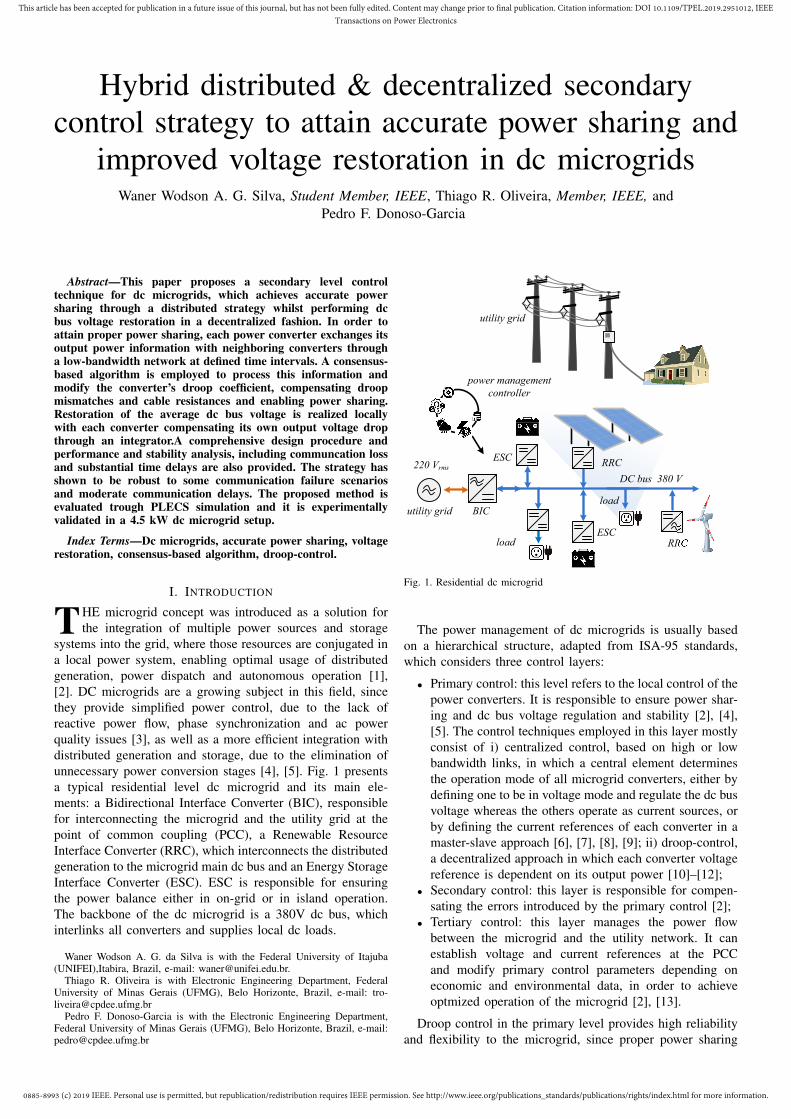
Fig. 12 shows system behavior against load perturbation andcommunication failures. The system initial condition is equalto the final values of Fig. 11. In t = 5.5s (event A), load RL2is connected to the dc bus, disturbing the output voltages ofthe power converters. However, the equivalent line resistancesare not affected, which does not introduces new power sharingmismatches. Therefore, all converters proportionally increasetheir output power not altering the steady state value ofthe droop correction terms, while the decentralized voltagecorrection gradually regulates the dc bus voltage. In t = 7.5s
0885-8993 (c) 2019 IEEE. Personal use is permitted, but republication/redistribution requires IEEE permission. See http://www.ieee.org/publications_standards/publications/rights/index.html for more information.
This article has been accepted for publication in a future issue of this journal, but has not been fully edited. Content may change prior to final publication. Citation information: DOI 10.1109/TPEL.2019.2951012, IEEETransactions on Power Electronics
370
375
380
385
390
Ou
tpu
t v
olt
ag
e (V
)
vo1
vo2
vo3
vo avg
0
2.5
5
7.5
Ou
tpu
t cu
rren
t (A
)
io1
io2
io3
500
1250
2000
2750
Po
wer
(W
)
P1
P2
P3
4 6 8 10 12 14 16 18
time (s)
-1.3
-0.65
0
0.65
1.3
Rd R
d1 R
d2 R
d3
A B C D E F
Fig. 12. System behavior under load perturbation and communicationfailures
(B), there is a communication failure between Conv-1 andConv-3, however, since there was no load and line resistancealterations, the correction of voltage deviation and powersharing were preserved. In t = 9s (C), RL3 is connected tothe dc bus, causing a new disturbance on the output voltagesand an alteration on equivalent line impedances, hence, thesecondary control calculates new values of δRd for ensuringpower sharing. In this case, convergence occurred in tp = 0.1s.
At t = 11.5s (D), a new communication failure occurs, nowbetween Conv-2 and Conv-3, which leaves Conv-3 isolatedfrom the other converters. Since it receives no data from theremainder converters, voltage deviation correction is halted,holding the last δvo3 and δRd3 values. Accurate power sharingwill be ensured, as long as there are no equivalent lineimpedance changes. In t = 13s (E), RL2 is disconnected fromthe dc bus, perturbing the dc bus voltage and modifying theequivalent line impedance. It can be observed that the powerratio between Conv-1 and Conv-2 is conserved, regardlessof Conv-3. The voltage deviation correction performed byconverters 1 and 2 is still active, which reduces the dc busvoltage error, but increases the difference between the outputcurrents io2 and io3. The droop correction terms converged toδRd1 = −0.522Ω, δRd2 = −0.154Ω and δRd3 = 0.735Ω.Finally, at t = 15s (F), the communication with Conv-3 isrestored and as a result the accurate power sharing among thethree converters is restored as well.
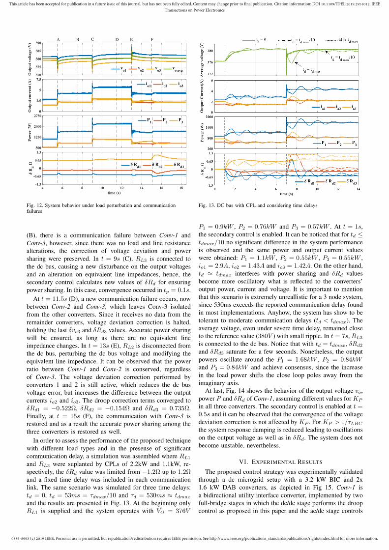
In order to assess the performance of the proposed techniquewith different load types and in the presense of significantcommunication delay, a simulation was assembled where RL1and RL3 were suplanted by CPLs of 2.2kW and 1.1kW, re-spectively, the δRd value was limited from −1.2Ω up to 1.2Ωand a fixed time delay was included in each communicationlink. The same scenario was simulated for three time delays:td = 0, td = 53ms = τdmax/10 and τd = 530ms ≈ tdmaxand the results are presented in Fig. 13. At the beginning onlyRL1 is supplied and the system operates with VO = 376V
Fig. 13. DC bus with CPL and considering time delays
P1 = 0.9kW , P2 = 0.76kW and P3 = 0.57kW . At t = 1s,the secondary control is enabled. It can be noticed that for td ≤tdmax/10 no significant difference in the system performanceis observed and the same power and output current valueswere obtained: P1 = 1.1kW , P2 = 0.55kW , P3 = 0.55kW ,io1 = 2.9A, io2 = 1.43A and io3 = 1.42A. On the other hand,td ≈ tdmax interferes with power sharing and δRd valuesbecome more oscillatory what is reflected to the converters’output power, current and voltage. It is important to mentionthat this scenario is extremely unreallistic for a 3 node system,since 530ms exceeds the reported communication delay foundin most implementations. Anyhow, the system has show to betolerant to moderate commnication delays (td < tdmax). Theaverage voltage, even under severe time delay, remained closeto the reference value (380V ) with small ripple. In t = 7s, RL3is connected to the dc bus. Notice that with td = tdmax, δRd2and δRd3 saturate for a few seconds. Nonetheless, the outputpowers oscillate around the P1 = 1.68kW , P2 = 0.84kWand P3 = 0.84kW and achieve consensus, since the increasein the load power shifts the close loop poles away from theimaginary axis.
At last, Fig. 14 shows the behavior of the output voltage vo,power P and δRd of Conv-1, assuming different values for KP
in all three converters. The secondary control is enabled at t =0.5s and it can be observed that the convergence of the voltagedeviation correction is not affected by KP . For KP > 1/τLBCthe system response damping is reduced leading to oscillationson the output voltage as well as in δRd. The system does notbecome unstable, nevertheless.
VI. EXPERIMENTAL RESULTS
The proposed control strategy was experimentally validatedthrough a dc microgrid setup with a 3.2 kW BIC and 2x1.6 kW DAB converters, as depicted in Fig 15. Conv-1 isa bidirectional utility interface converter, implemented by twofull-bridge stages in which the dc/dc stage performs the droopcontrol as proposed in this paper and the ac/dc stage controls

0885-8993 (c) 2019 IEEE. Personal use is permitted, but republication/redistribution requires IEEE permission. See http://www.ieee.org/publications_standards/publications/rights/index.html for more information.
This article has been accepted for publication in a future issue of this journal, but has not been fully edited. Content may change prior to final publication. Citation information: DOI 10.1109/TPEL.2019.2951012, IEEETransactions on Power Electronics
378
380
382
Ou
tpu
t v
olt
ag
e (V
)
Kp
= 10 Kp
= 20 Kp
= 40 Kp
= 80
800
1000
1200
1400
Po
wer
(W
)
Kp
= 10 Kp
= 20 Kp
= 40 Kp
= 80
0 0.5 1 1.5 2 2.5 3 3.5 4
time (s)
-1
-0.5
0
Rd
Kp
= 10 Kp
= 20 Kp
= 40 Kp
= 80
Fig. 14. Results of Conv-1 to different values of KP
the injected utility current in order to regulate the inner dclink at 550V. The dc link capacitance is designed so thedynamics of both stages are decoupled, therefore, the ac/dccontrol diagram will be omitted here. Conv-2 and Conv-3 areDAB converters that interface the dc bus to two battery banks.The control system, in each converter, was implemented ona TMS320F28335 Texas Instruments DSP and a 500 kbpsCAN 2.0 communication network was employed to exchangeinformation among converters. A Raspberry Pi 3 is alsoattached to the CAN network and was used as a datalogger.The converter parameters are the ones described in Table III.
The results without load perturbation are shown in Fig. 16.For t < 1s, the output power of Conv-1, Conv-2 and Conv-3 are 0.9kW , 0.58kW and 0.77kW , respectively, and theaverage voltage voavg = 376.1V . In t = 1s the secondarycontrol is enabled. The power sharing convergence time isobserved to be tp ≈ 1.2s and the voltage deviation correctionoccurred in tv = 2.5s, once again the simplification adoptedin (9) is confirmed. The output power of Conv-1, Conv-2and Conv-3 converged to 1.16kW , 0.58kW and 0.58kW ,respectively. It can be observed that with the secondary controlthe power sharing is proportional the respective designedcapacities of the converters. The droop correction terms areδRd1 = −0.469Ω, δRd2 = −0.172Ω and δRd3 = 0.499Ω,but δRd1 + δRd2 + δRd3 = −0.142Ω, this can be explainedby measurement inaccuracies. The output currents are io1 =2.98A, io2 = 1.52A and io3 = 1.51A
Fig. 17 shows the results for a series of load perturbationsoccurring right after the previous experiment. Load RL2 isconnect to the dc bus at t = 5.5s (A). A priori, this load wouldnot cause changes in the equivalent line impedances, however,there are resistances that were not modelled, e.g., connectors,thus a perturbation in the line impedance is sensed by Conv-3,which changes δRd3 from 0.478Ω to 0.243Ω in tp = 0.9s.
A loss of communication occurs at t = 7.4s (B) betweenConv-1 and Conv-3, which does not influence the powersharing and voltage regulation. At t = 9s (C), load RL3is connected to the dc bus. Power sharing convergence isachieved in tp = 0.9s. It can be observed that this eventdid not provoke significant alterations in the values of thedroop correction terms. The communication between Conv-1 and Conv-3 is restored at t = 11.4s (D) and in t = 13s
Fig. 15. DC microgrid experimental
372
375
378
381
384
Ou
tpu
t v
olt
ag
e (V
)
vo1
vo2
vo3
vo avg
0
1.5
3
4.5
Ou
tpu
t cu
rren
t (A
)
io1
io2
io3
250
750
1250
1750
Po
wer
(W
)
P1
P2
P3
0 0.5 1 1.5 2 2.5 3 3.5 4
time (s)
-1
-0.5
0
0.5
1
Rd R
d1 R
d2 R
d3
tv
tp
vo avg
= 376.1
vo avg
= 379.8
Fig. 16. Experimental results up to complete dc bus voltage restoration
(E) the load RL2 is disconnected from the dc bus. Onceagain, it can be observed that the proposed technique ensuresproportional power sharing and that he voltage deviation

0885-8993 (c) 2019 IEEE. Personal use is permitted, but republication/redistribution requires IEEE permission. See http://www.ieee.org/publications_standards/publications/rights/index.html for more information.
This article has been accepted for publication in a future issue of this journal, but has not been fully edited. Content may change prior to final publication. Citation information: DOI 10.1109/TPEL.2019.2951012, IEEETransactions on Power Electronics
370
375
380
385
390
Ou
tpu
t v
olt
ag
e (V
)
vo1
vo2
vo3
vo avg
0
2.5
5
7.5
Ou
tpu
t cu
rren
t (A
)
io1
io2
io3
500
1250
2000
2750
Po
wer
(W
)
P1
P2
P3
4 5 6 7 8 9 10 11 12 13 14 15
time (s)
-1
-0.5
0
0.5
1
Rd
Rd1
Rd2
Rd3
tpt
p
vo avg
=
379.8
EDC
vo avg
=
380.1
Bv
o avg=
380.1
A
Fig. 17. Experimental results considering load perturbations andcommunication failure
correction was successful in regulating the dc bus averagevoltage to voavg ≈ V ∗. It can also be observed that theintrinsic time delay present in the CAN 2.0 communicationlink did not interfere with the system behavior.
VII. CONCLUSION
In this paper, a secondary level control strategy was pro-posed for achieving accurate power sharing and dc bus voltagerestoration for dc microgrids. The proposed technique uses adistributed consensus-based algorithm to define a proper droopcoefficient adjustment term that will be added to the droopcontroller of the power converters connected to the main dcbus of a microgrid, in order to compensate the influence ofline impedance mismatches and promote accurate proportionalpower sharing. The algorithm relies solely on output power in-formation exchanged between neighboring converters througha low bandwidth communication network. If the communi-cations fails, but one neighbor is still communicating, powersharing is ensured. Voltage deviation correction is achievedby a decentralized action, which generates a voltage shiftingterm to be added to the converter voltage reference through anaccumulator that compensates the voltage drop introduced bythe converter droop coefficient. The strategy has shown to bestable under different parameter variations and robust to somecommunication failure events and moderate time delays. Theperformance of the proposed method was validated experi-mentally, showing a robust strategy able to reach proportionalpower sharing and dc bus regulation with low communicationtraffic, resiliency to communication failures and simplicity.
REFERENCES
[1] R. H. Lasseter, A. A. Akhil, C. Marnay, J. Stephens, J. E. Dagle, R. T.Guttromson, A. S. Meliopoulous, R. J. Yinger, and J. H. Eto, “Integrationof distributed energy resources: The certs microgrid concept,” CERTS,Tech. Rep., 10/2003 2003.
[2] J. M. Guerrero, J. C. Vasquez, J. Matas, M. Castilla, and L. G. de Vicuna,“Control strategy for flexible microgrid based on parallel line-interactiveups systems,” IEEE Transactions on Industrial Electronics, vol. 56,no. 3, pp. 726–736, March 2009.
[3] K. D. Hoang and H. Lee, “Accurate power sharing with balanced batterystate of charge in distributed dc microgrid,” IEEE Transactions onIndustrial Electronics, vol. 66, no. 3, pp. 1883–1893, March 2019.
[4] X. Lu, J. M. Guerrero, K. Sun, and J. C. Vasquez, “An improveddroop control method for dc microgrids based on low bandwidthcommunication with dc bus voltage restoration and enhanced currentsharing accuracy,” IEEE Transactions on Power Electronics, vol. 29,no. 4, pp. 1800–1812, April 2014.
[5] P. Huang, P. Liu, W. Xiao, and M. S. E. Moursi, “A novel droop-based average voltage sharing control strategy for dc microgrids,” IEEETransactions on Smart Grid, vol. 6, no. 3, pp. 1096–1106, May 2015.
[6] J. Banda and K. Siri, “Improved central-limit control for parallel-operation of dc-dc power converters,” in Proceedings of PESC ’95 -Power Electronics Specialist Conference, vol. 2, June 1995, pp. 1104–1110 vol.2.
[7] J. Rajagopalan, K. Xing, Y. Guo, F. C. Lee, and B. Manners, “Modelingand dynamic analysis of paralleled dc/dc converters with master-slavecurrent sharing control,” in Proceedings of Applied Power ElectronicsConference. APEC ’96, vol. 2, March 1996, pp. 678–684 vol.2.
[8] X. Sun, Y.-S. Lee, and D. Xu, “Modeling, analysis, and implementationof parallel multi-inverter systems with instantaneous average-current-sharing scheme,” IEEE Transactions on Power Electronics, vol. 18,no. 3, pp. 844–856, May 2003.
[9] R. Pradhan, M. Chirayath, and S. Thale, “Coordinated control strategyfor a dc microgrid with low bandwidth communication,” in 2016 IEEEInternational Conference on Power Electronics, Drives and EnergySystems (PEDES), Dec 2016, pp. 1–6.
[10] J. M. Guerrero, J. C. Vasquez, J. Matas, J. L. Sosa, and L. G.de Vicuna, “Parallel operation of uninterruptible power supply systemsin microgrids,” in 2007 European Conference on Power Electronics andApplications, Sept 2007, pp. 1–9.
[11] X. Lu, J. M. Guerrero, K. Sun, J. C. Vasquez, R. Teodorescu, andL. Huang, “Hierarchical control of parallel ac-dc converter interfacesfor hybrid microgrids,” IEEE Transactions on Smart Grid, vol. 5, no. 2,pp. 683–692, March 2014.
[12] C. Jin, J. Wang, and P. Wang, “Coordinated secondary control forautonomous hybrid three-port ac/dc/ds microgrid,” CSEE Journal ofPower and Energy Systems, vol. 4, no. 1, pp. 1–10, March 2018.
[13] J. M. Guerrero, J. C. Vasquez, J. Matas, L. G. de Vicuna, and M. Castilla,“Hierarchical control of droop-controlled ac and dc microgrids—a gen-eral approach toward standardization,” IEEE Transactions on IndustrialElectronics, vol. 58, no. 1, pp. 158–172, Jan 2011.
[14] T. Dragicevic, J. M. Guerrero, J. C. Vasquez, and D. Skrlec, “Supervisorycontrol of an adaptive-droop regulated dc microgrid with battery man-agement capability,” IEEE Transactions on Power Electronics, vol. 29,no. 2, pp. 695–706, Feb 2014.
[15] J. Xiao, P. Wang, and L. Setyawan, “Hierarchical control of hybrid en-ergy storage system in dc microgrids,” IEEE Transactions on IndustrialElectronics, vol. 62, no. 8, pp. 4915–4924, Aug 2015.
[16] D. Dam and H. Lee, “A power distributed control method for propor-tional load power sharing and bus voltage restoration in a dc microgrid,”IEEE Transactions on Industry Applications, vol. 54, no. 4, pp. 3616–3625, July 2018.
[17] S. Anand, B. G. Fernandes, and J. Guerrero, “Distributed control toensure proportional load sharing and improve voltage regulation inlow-voltage dc microgrids,” IEEE Transactions on Power Electronics,vol. 28, no. 4, pp. 1900–1913, April 2013.
[18] L. Meng, T. Dragicevic, J. Roldan-Perez, J. C. Vasquez, and J. M.Guerrero, “Modeling and sensitivity study of consensus algorithm-baseddistributed hierarchical control for dc microgrids,” IEEE Transactions onSmart Grid, vol. 7, no. 3, pp. 1504–1515, May 2016.
[19] H. Wang, M. Han, J. M. Guerrero, J. C. Vasquez, and B. G. Teshager,“Distributed secondary and tertiary controls fori–vdroop-controlled-paralleled dc–dc converters,” IET Generation, Transmission Distribution,vol. 12, no. 7, pp. 1538–1546, 2018.
[20] L. Guo, Z. Guo, X. Li, C. Wang, C. Hong, and Y. Zhang, “Consensus-based distributed coordinated control for islanded dc microgrids,” in2017 IEEE Power Energy Society General Meeting, July 2017, pp. 1–5.
[21] X. Zhang, M. Dong, and J. Ou, “A distributed cooperative controlstrategy based on consensus algorithm in dc microgrid,” in 2018 13thIEEE Conference on Industrial Electronics and Applications (ICIEA),May 2018, pp. 243–248.
[22] F. Chen, R. Burgos, D. Boroyevich, E. Rodriguez-Diaz, L. Meng,J. C. Vasquez, and J. M. Guerrero, “Analysis and distributed controlof power flow in dc microgrids to improve system efficiency,” in 20164th International Symposium on Environmental Friendly Energies andApplications (EFEA), Sep. 2016, pp. 1–6.

0885-8993 (c) 2019 IEEE. Personal use is permitted, but republication/redistribution requires IEEE permission. See http://www.ieee.org/publications_standards/publications/rights/index.html for more information.
This article has been accepted for publication in a future issue of this journal, but has not been fully edited. Content may change prior to final publication. Citation information: DOI 10.1109/TPEL.2019.2951012, IEEETransactions on Power Electronics
[23] D. O’Keeffe, S. Riverso, L. Albiol-Tendillo, and G. Lightbodyt, “Dis-tributed hierarchical droop control of boost converters in dc microgrids,”in 2017 28th Irish Signals and Systems Conference (ISSC), June 2017,pp. 1–6.
[24] S. Moayedi and A. Davoudi, “Unifying distributed dynamic optimizationand control of islanded dc microgrids,” IEEE Transactions on PowerElectronics, vol. 32, no. 3, pp. 2329–2346, March 2017.
[25] M. A. Mumtaz, M. M. Khan, F. Xianghong, A. Karni, and M. T. Faiz,“An improved cooperative control method of dc microgrids based onfinite gain controller,” in 2018 20th European Conference on PowerElectronics and Applications (EPE’18 ECCE Europe), Sep. 2018, pp.P.1–P.9.
[26] D. Pullaguram, S. Mishra, and N. Senroy, “Event-triggered commu-nication based distributed control scheme for dc microgrid,” IEEETransactions on Power Systems, vol. 33, no. 5, pp. 5583–5593, Sep.2018.
[27] M. Cucuzzella, S. Trip, C. De Persis, X. Cheng, A. Ferrara, and A. vander Schaft, “A robust consensus algorithm for current sharing and voltageregulation in dc microgrids,” IEEE Transactions on Control SystemsTechnology, pp. 1–13, 2018.
[28] S. Sahoo and S. Mishra, “A distributed finite-time secondary averagevoltage regulation and current sharing controller for dc microgrids,”IEEE Transactions on Smart Grid, vol. 10, no. 1, pp. 282–292, Jan2019.
[29] J. Hu, J. Duan, H. Ma, and M. Chow, “Distributed adaptive droopcontrol for optimal power dispatch in dc microgrid,” IEEE Transactionson Industrial Electronics, vol. 65, no. 1, pp. 778–789, Jan 2018.
[30] P. Wang, X. Lu, X. Yang, W. Wang, and D. Xu, “An improved distributedsecondary control method for dc microgrids with enhanced dynamiccurrent sharing performance,” IEEE Transactions on Power Electronics,vol. 31, no. 9, pp. 6658–6673, Sept 2016.
[31] V. Nasirian, A. Davoudi, F. L. Lewis, and J. M. Guerrero, “Distributedadaptive droop control for dc distribution systems,” IEEE Transactionson Energy Conversion, vol. 29, no. 4, pp. 944–956, Dec 2014.
[32] M. Zaery, E. M. Ahmed, M. Orabi, and M. Youssef, “Operational costreduction based on distributed adaptive droop control technique in dcmicrogrids,” in 2017 IEEE Energy Conversion Congress and Exposition(ECCE), Oct 2017, pp. 2638–2644.
[33] Q. Xu, J. Xiao, X. Hu, P. Wang, and M. Y. Lee, “A decentralized powermanagement strategy for hybrid energy storage system with autonomousbus voltage restoration and state-of-charge recovery,” IEEE Transactionson Industrial Electronics, vol. 64, no. 9, pp. 7098–7108, Sep. 2017.
[34] Introduction to the Controller Area Network (CAN), Texas Instruments,8 2002, revised May 2016.
[35] R. Olfati-Saber, J. A. Fax, and R. M. Murray, “Consensus and coop-eration in networked multi-agent systems,” Proceedings of the IEEE,vol. 95, no. 1, pp. 215–233, Jan 2007.
[36] L. Meng, T. Dragicevic, J. M. Guerrero, and J. C. Vasquez, “Dynamicconsensus algorithm based distributed global efficiency optimization ofa droop controlled dc microgrid,” in 2014 IEEE International EnergyConference (ENERGYCON), May 2014, pp. 1276–1283.
[37] B. Van Scoy, R. A. Freeman, and K. M. Lynch, “Exploiting memory indynamic average consensus,” in 2015 53rd Annual Allerton Conferenceon Communication, Control, and Computing (Allerton), Sep. 2015, pp.258–265.
[38] S. S. Kia, B. V. Scoy, J. Cortes, R. A. Freeman, K. M. Lynch, andS. Martınez, “Tutorial on dynamic average consensus: the problem, itsapplications, and the algorithms,” CoRR, vol. abs/1803.04628, 2018.
[39] R. Olfati-Saber and R. M. Murray, “Consensus problems in networksof agents with switching topology and time-delays,” IEEE Transactionson Automatic Control, vol. 49, no. 9, pp. 1520–1533, Sep. 2004.
[40] T. Morstyn, B. Hredzak, G. D. Demetriades, and V. G. Agelidis,“Unified distributed control for dc microgrid operating modes,” IEEETransactions on Power Systems, vol. 31, no. 1, pp. 802–812, Jan 2016.