hybrid energy storage system optimal sizing for urban
TRANSCRIPT
International Journal of Electrical and Computer Engineering (IJECE)
Vol. 10, No. 3, June 2020, pp. 2894~2911
ISSN: 2088-8708, DOI: 10.11591/ijece.v10i3.pp2894-2911 2894
Journal homepage: http://ijece.iaescore.com/index.php/IJECE
Hybrid energy storage system optimal sizing for urban
electrical bus regarding battery thermal behavior
Si Mohamed Faresse, Mohamed Assini, Abdallah Saad Laboratory of Electrical Systems and Energy, National Higher School of Electricity and Mechanics (ENSEM),
Hassan II University of Casablanca, Morocco
Article Info ABSTRACT
Article history:
Received April 19, 2019
Revised Dec 31, 2019
Accepted Jan 8, 2020
This paper proposes an algorithm for sizing the hybrid energy storage system
of an urban electrical bus regarding battery thermal behavior. The aim of this
study is to get the supercapacitors optimal contribution part in the hybrid
energy storage system to keep the battery temperature within its allowable
limit. A semi-active parallel topology that uses supercapacitors as a main
source of energy is considered. According to the bus mechanical parameters
and the ARTEMIS driving cycle, the power and energy demand are
calculated. Using mathematical models for the battery, supercapacitors and
DC-DC converter, several simulations are performed for different
hybridization percentages. While observing the evolution of battery
temperature, the most favorable hybridization percentage is defined.
Keywords:
Battery
Battery thermal behavior
Buck-boost DC/DC converter
Fully electrical bus
Hybrid energy storage system
Supercapacitor
Copyright © 2020 Institute of Advanced Engineering and Science.
All rights reserved.
Corresponding Author:
Si Mohamed Faresse,
Laboratory of Electrical Systems and Energy,
Department of Electrical Engineering,
National Higher School of Electricity and Mechanics,
Hassan II University of Casablanca,
El Jadida Road, km 7, Casablanca, Morocco.
Email: [email protected]
NOMENCLATURE
Vbatt Battery voltage (V)
E0 Constant voltage (V)
K Polarization constant (Ah−1)
i* Low frequency current dynamics (A)
I Battery current (A)
it Extracted capacity (Ah)
Q Maximum battery capacity (Ah)
A Exponential voltage (V)
B Exponential capacity (Ah−1)
Rb Battery internal resistance (Ω)
Tref Nominal ambient temperature (K)
T Cell or internal temperature (K)
Ta Ambient temperature (K)
∂E/∂T Reversible voltage temperature coefficient (V/K)
α Arrhenius rate constant for the polarization resistance
β Arrhenius rate constant for the internal resistance
ΔQ/ΔT Maximum capacity temperature coefficient (Ah/K)

Int J Elec & Comp Eng ISSN: 2088-8708
Hybrid energy storage system optimal sizing for urban electrical… (Si Mohamed Faresse)
2895
C Nominal discharge curve slope (V/Ah)
Rth Thermal resistance, cell to ambient (°C/W)
tc Thermal time constant, cell to ambient (s)
Ploss Overall heat generated during charge/discharge (W)
isc Supercapacitor current (A)
Vsc Supercapacitor voltage (V)
Rsc Supercapacitor total resistance (ohms)
Ne Number of layers of electrodes
Np Number of parallel supercapacitors
Ns Number of series supercapacitors
QT Electric charge (C)
R Ideal gas constant
d Molecular radius
To Operating temperature (K)
Ε Permittivity of material
ε0 Permittivity of free space
Ai Interfacial area between electrodes and electrolyte (m2)
c Molar concentration (mol/m3)
F Faraday constant
Ftr Tractive force (N)
Faero Aerodynamic drag (N)
Frr Rolling resistance (N)
Fi Inirtial force (N)
Fgr Grade force (N)
ρ Air density
Cd Air drag coefficient
Af Front Surface (m2)
V Velocity (m/s)
m Total mass (kg)
g Gravitational force (m.s-2)
θ Drag angle (rad)
Cr Rolling friction factor
a Acceleration (m.s-2)
rw Wheel radius (m)
id Gear transmission ratio
ηd Gear transmission efficiency
Ω Angular speed (rad.s-1)
P Power (W)
T Torque (N.m)
1. INTRODUCTION
The first autonomous electric buses were equipped with batteries as a source of energy [1]. These batteries have some disadvantages, namely a too slow dynamic [2] and overheating problem [3,4]. The combination of batteries and supercapacitors (SC) is the suitable solution for electric vehicle [5]. This combination has complementary qualities and provides an excellent solution that can increase dynamic behavior and cover a wide range of power and energy requirements and it was demonstrated that this combination has lower battery costs [6], a general increase in battery life and higher overall system efficiency [7]. Starting from the observation that battery buses are used almost exclusively in urban areas rather than for long-distance transport. The urban transport has relatively short intervals between recharging possibilities. Externally based energy storage on SC can be a solution since they can charge much faster than conventional batteries [8].
In the literature, most of the reported works focus solely on the electrical behavior of hybrid energy storage system (HESS). While the behavior of the battery temperature in this kind of application has not yet been treated. All HESS sizing methodologies for electric buses do not considerate the battery temperature evolution. And to remedy to this problem, supercapacitors oversizing is done.
Obviously, HESS topologies are very diverse, depending mainly on the type of application [9]. For the studied case, the selected topology will use the SC as the main source [10]. Our study is to redo this dimensioning while considering the temperature of the battery to choose the optimal capacity value of
ISSN: 2088-8708
Int J Elec & Comp Eng, Vol. 10, No. 3, June 2020 : 2894 - 2911
2896
supercapacitors. In this study, an algorithm is proposed to define the minimum SC energy part in the hybrid storage system for electrical bus to maintain the battery in its permissible temperature zone. In this work we neglected the regenerative braking energy. The suggested algorithm is applied to "Irizar ie" bus, with a total mass of 16000 kg following an ARTEMIS driving cycle on a working day of 24 round trips. Total energy required is calculated. Then, capacity part of each element is defined and for each percentage of hybridization the temperature evolution is determined using battery model which consider temperature effect.
This paper is organized as follows: After the Introduction is given in the first section, the System Description and Modeling are introduced in section 2. The Research Method is presented in section 3. Then, the Electric Bus Energy Storage Sizing is addressed in section 4. Finally, section Simulation Results develops battery thermal behavior for different percentage of hybridization. The conclusions are given in the last section.
2. DESCRIPTION AND SYSTEM MODELING
2.1. Hybrid energy storage system topologies
Four possible topologies [11,12,13] for the HESS are presented below:
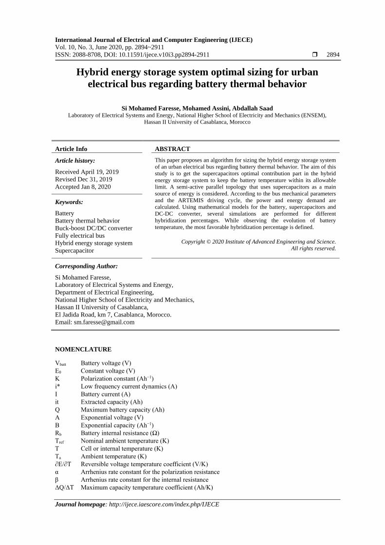
2.2.1. Parallel passive topology
The basic passive parallel hybrid configuration is shown in Figure 1, the SC pack and the batteries
are directly connected in parallel to the load. Because of the direct connection, the SC pack basically acts as
a low-pass filter. The main advantage is the ease of implementation and no complicated control device
required. The disadvantage of this configuration is that the power sharing between the battery and the SC
pack is uncontrolled and dictated solely by the parasitic elements. Also the DC bus voltage is not regulated
and varies depending on the voltage range of the batteries, which influences the design load.
Figure 1. Passive parallel hybrid configuration
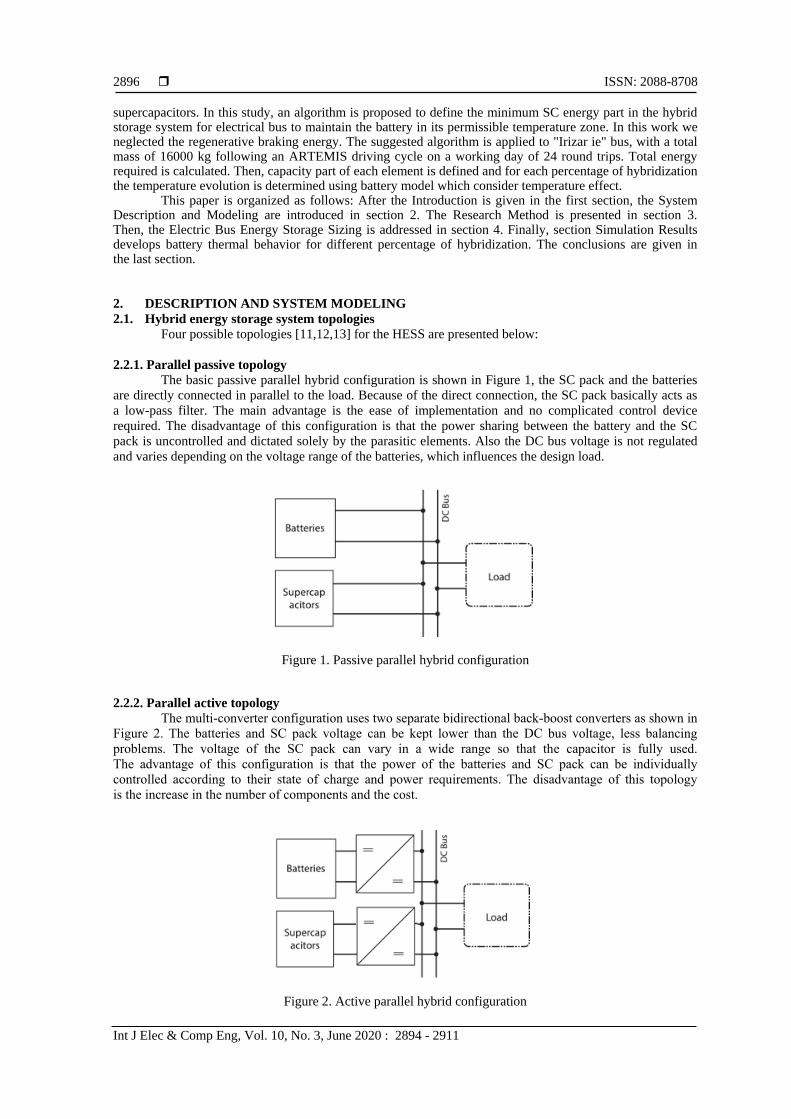
2.2.2. Parallel active topology
The multi-converter configuration uses two separate bidirectional back-boost converters as shown in
Figure 2. The batteries and SC pack voltage can be kept lower than the DC bus voltage, less balancing
problems. The voltage of the SC pack can vary in a wide range so that the capacitor is fully used.
The advantage of this configuration is that the power of the batteries and SC pack can be individually
controlled according to their state of charge and power requirements. The disadvantage of this topology
is the increase in the number of components and the cost.
Figure 2. Active parallel hybrid configuration
Int J Elec & Comp Eng ISSN: 2088-8708
Hybrid energy storage system optimal sizing for urban electrical… (Si Mohamed Faresse)
2897
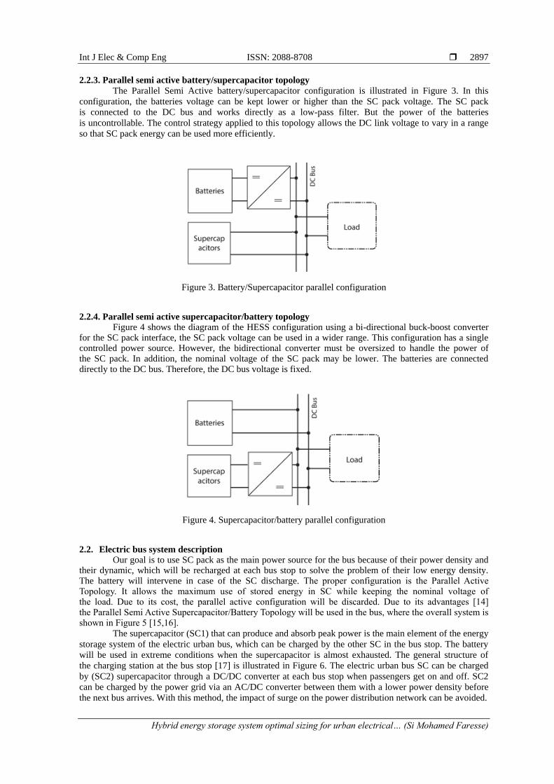
2.2.3. Parallel semi active battery/supercapacitor topology
The Parallel Semi Active battery/supercapacitor configuration is illustrated in Figure 3. In this
configuration, the batteries voltage can be kept lower or higher than the SC pack voltage. The SC pack
is connected to the DC bus and works directly as a low-pass filter. But the power of the batteries
is uncontrollable. The control strategy applied to this topology allows the DC link voltage to vary in a range
so that SC pack energy can be used more efficiently.
Figure 3. Battery/Supercapacitor parallel configuration
2.2.4. Parallel semi active supercapacitor/battery topology Figure 4 shows the diagram of the HESS configuration using a bi-directional buck-boost converter for the SC pack interface, the SC pack voltage can be used in a wider range. This configuration has a single controlled power source. However, the bidirectional converter must be oversized to handle the power of the SC pack. In addition, the nominal voltage of the SC pack may be lower. The batteries are connected directly to the DC bus. Therefore, the DC bus voltage is fixed.
Figure 4. Supercapacitor/battery parallel configuration
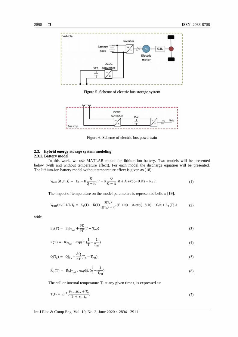
2.2. Electric bus system description Our goal is to use SC pack as the main power source for the bus because of their power density and
their dynamic, which will be recharged at each bus stop to solve the problem of their low energy density. The battery will intervene in case of the SC discharge. The proper configuration is the Parallel Active Topology. It allows the maximum use of stored energy in SC while keeping the nominal voltage of the load. Due to its cost, the parallel active configuration will be discarded. Due to its advantages [14] the Parallel Semi Active Supercapacitor/Battery Topology will be used in the bus, where the overall system is shown in Figure 5 [15,16].
The supercapacitor (SC1) that can produce and absorb peak power is the main element of the energy
storage system of the electric urban bus, which can be charged by the other SC in the bus stop. The battery
will be used in extreme conditions when the supercapacitor is almost exhausted. The general structure of
the charging station at the bus stop [17] is illustrated in Figure 6. The electric urban bus SC can be charged
by (SC2) supercapacitor through a DC/DC converter at each bus stop when passengers get on and off. SC2
can be charged by the power grid via an AC/DC converter between them with a lower power density before
the next bus arrives. With this method, the impact of surge on the power distribution network can be avoided.
ISSN: 2088-8708
Int J Elec & Comp Eng, Vol. 10, No. 3, June 2020 : 2894 - 2911
2898
Figure 5. Scheme of electric bus storage system
Figure 6. Scheme of electric bus powertrain
2.3. Hybrid energy storage system modeling
2.3.1. Battery model
In this work, we use MATLAB model for lithium-ion battery. Two models will be presented
below (with and without temperature effect). For each model the discharge equation will be presented.
The lithium-ion battery model without temperature effect is given as [18]:
Vbatt(it , i∗, i) = E0 − KQ
Q − it. i∗ − K
Q
Q − it. it + A. exp(−B. it) − R𝑏 . i (1)
The impact of temperature on the model parameters is represented bellow [19]:
Vbatt(it , i∗, i, T, Ta = E0(T) − K(T)Q(Ta)
Q(Ta) − it. (i∗ + it) + A. exp(−B. it) − C. it + Rb(T) . i (2)
with:
E0(T) = E0|Tref+
∂E
∂T(T − Tref) (3)
K(T) = K|Tref . exp(α. (
1
T−
1
Tref) (4)
Q(Ta) = Q|Ta+
∆Q
∆T(Ta − Tref) (5)
Rb(T) = Rb|Tref . exp(β. (
1
T−
1
Tref) (6)
The cell or internal temperature T, at any given time t, is expressed as:
T(t) = 𝐿−1(𝑃𝑙𝑜𝑠𝑠𝑅𝑡ℎ + 𝑇𝑎
1 + 𝑠 . 𝑡c) (7)
Int J Elec & Comp Eng ISSN: 2088-8708
Hybrid energy storage system optimal sizing for urban electrical… (Si Mohamed Faresse)
2899
where:
P𝑙𝑜𝑠𝑠 = (E0(𝑇) − 𝑉batt(T)) . i +∂E
∂T. i . T (8)
2.3.2. Supercapacitor model
The SC is an emerging technology in the field of energy storage systems. Energy storage
is performed by the means of static charge rather than of an electro-chemical process that is inherent to
the battery [20]. The supercapacitor model used in this work is a generic MATLAB model parameterized to
represent most popular types of SC [21]. The SC output voltage is expressed using a Stern equation as:
V𝑠𝑐 = 𝑁𝑠𝑄𝑇𝑑
𝑁𝑝𝑁𝑒𝜀𝜀0𝐴𝑖 +
2𝑁𝑒𝑁𝑠𝑅𝑇𝑜
𝐹𝑠𝑖𝑛ℎ−1(
𝑄𝑇
𝑁𝑝𝑁𝑒2𝐴𝑖√8𝑅𝑇𝑜𝜀𝜀0𝑐
) − 𝑅𝑠𝑐 . 𝑖𝑠𝑐 (9)
With : 𝑄𝑇 = ∫ 𝑖𝑠𝑐 𝑑𝑡
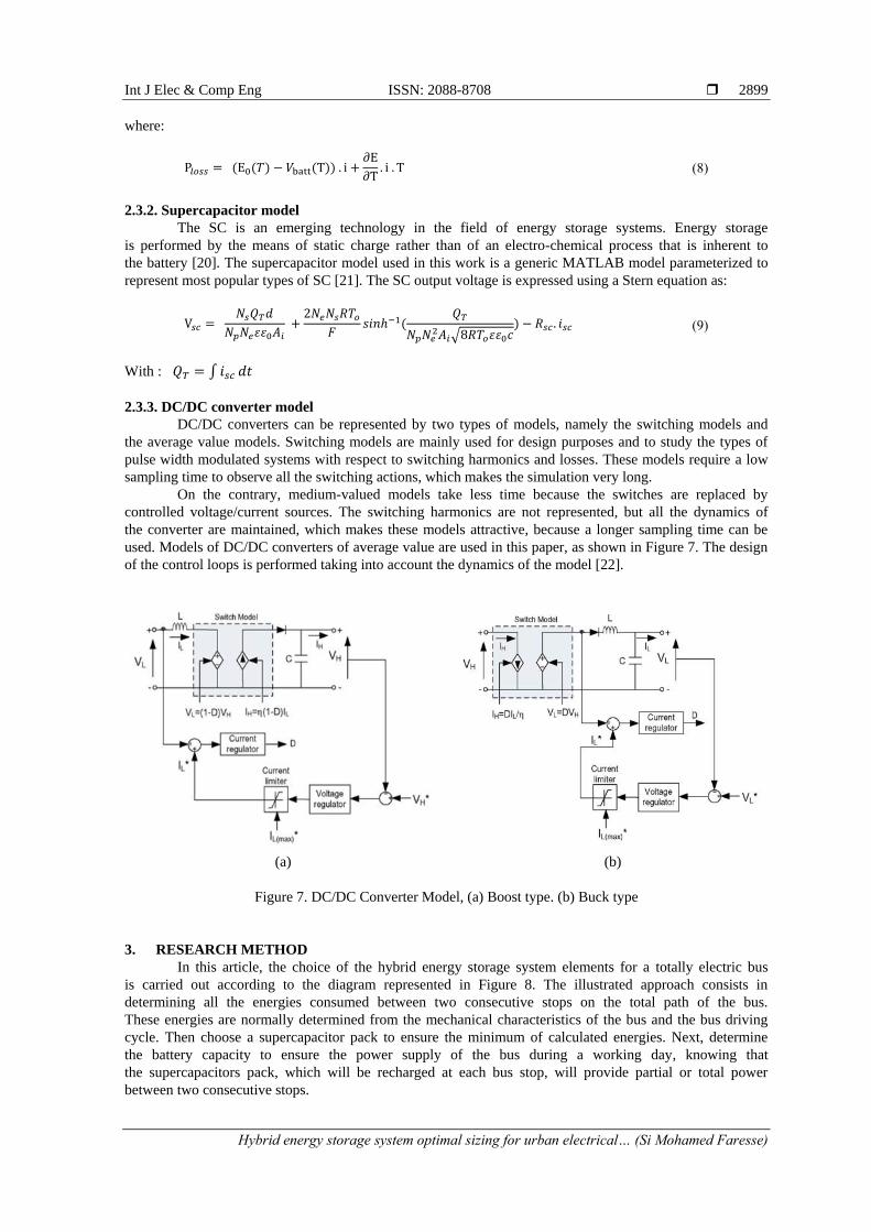
2.3.3. DC/DC converter model
DC/DC converters can be represented by two types of models, namely the switching models and
the average value models. Switching models are mainly used for design purposes and to study the types of
pulse width modulated systems with respect to switching harmonics and losses. These models require a low
sampling time to observe all the switching actions, which makes the simulation very long.
On the contrary, medium-valued models take less time because the switches are replaced by
controlled voltage/current sources. The switching harmonics are not represented, but all the dynamics of
the converter are maintained, which makes these models attractive, because a longer sampling time can be
used. Models of DC/DC converters of average value are used in this paper, as shown in Figure 7. The design
of the control loops is performed taking into account the dynamics of the model [22].
(a) (b)
Figure 7. DC/DC Converter Model, (a) Boost type. (b) Buck type
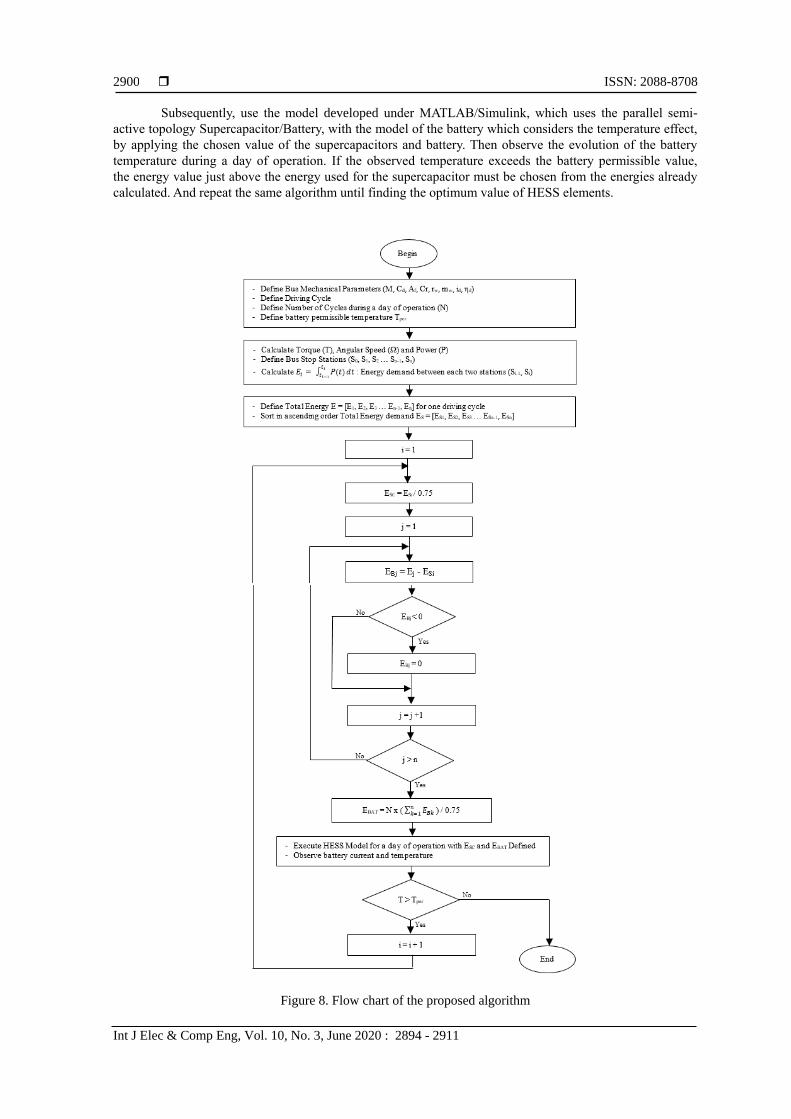
3. RESEARCH METHOD
In this article, the choice of the hybrid energy storage system elements for a totally electric bus
is carried out according to the diagram represented in Figure 8. The illustrated approach consists in
determining all the energies consumed between two consecutive stops on the total path of the bus.
These energies are normally determined from the mechanical characteristics of the bus and the bus driving
cycle. Then choose a supercapacitor pack to ensure the minimum of calculated energies. Next, determine
the battery capacity to ensure the power supply of the bus during a working day, knowing that
the supercapacitors pack, which will be recharged at each bus stop, will provide partial or total power
between two consecutive stops.
ISSN: 2088-8708
Int J Elec & Comp Eng, Vol. 10, No. 3, June 2020 : 2894 - 2911
2900
Subsequently, use the model developed under MATLAB/Simulink, which uses the parallel semi-
active topology Supercapacitor/Battery, with the model of the battery which considers the temperature effect,
by applying the chosen value of the supercapacitors and battery. Then observe the evolution of the battery
temperature during a day of operation. If the observed temperature exceeds the battery permissible value,
the energy value just above the energy used for the supercapacitor must be chosen from the energies already
calculated. And repeat the same algorithm until finding the optimum value of HESS elements.
Figure 8. Flow chart of the proposed algorithm
Int J Elec & Comp Eng ISSN: 2088-8708
Hybrid energy storage system optimal sizing for urban electrical… (Si Mohamed Faresse)
2901
4. ELECTRIC BUS ENERGY STORAGE SIZING The objective of this part is to size the energy storage system of a fully electrical bus from
well-defined specifications.
4.1. Bus mechanical parameters The main mechanical characteristics of the chosen bus are summarized in Table 1. The vehicle is constructed applying the body of “Irizar ie” bus with a new rear transmission ratio of 8.
Table 1. Bus mechanical parameters Parameters Symbol Values
Total mass (fully loaded) M 16 000 kg Air drag coefficient Cd 0.65 Front surface Af 8 m2
Rolling friction factor Cr 0.008 Wheel radius rw 0.48 m Wheel mass mw 50 kg Gear transmission ratio id 8 : 1 Gear transmission efficiency ηd 0.97
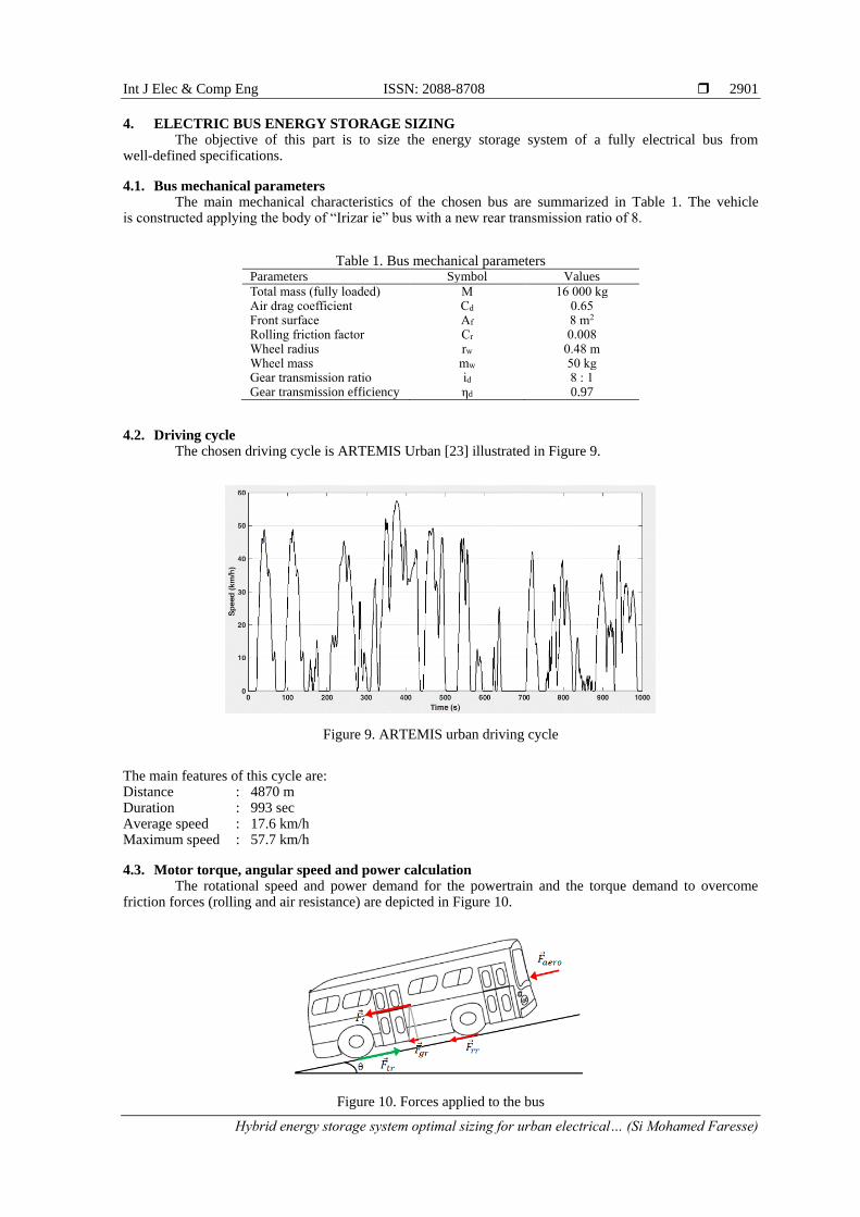
4.2. Driving cycle The chosen driving cycle is ARTEMIS Urban [23] illustrated in Figure 9.
Figure 9. ARTEMIS urban driving cycle
The main features of this cycle are: Distance : 4870 m Duration : 993 sec Average speed : 17.6 km/h Maximum speed : 57.7 km/h
4.3. Motor torque, angular speed and power calculation The rotational speed and power demand for the powertrain and the torque demand to overcome
friction forces (rolling and air resistance) are depicted in Figure 10.
Figure 10. Forces applied to the bus

ISSN: 2088-8708
Int J Elec & Comp Eng, Vol. 10, No. 3, June 2020 : 2894 - 2911
2902
The bus traction force required is given by this equation [24-26]:
𝐹tr = 𝐹aero + 𝐹rr + 𝐹i + 𝐹gr (10)
where:
𝐹aero = 12⁄ 𝜌 𝐶𝑑 𝐴𝑓 𝑉2 (11)
𝐹rr = m g sin() (12)
𝐹𝑔𝑟 = m g 𝐶𝑟 (13)
𝐹i = a 𝑚𝑖 (14)
𝑚𝑖 = 1.04 𝑚 (15)
a =𝐹tr − (𝐹aero + 𝐹rr + 𝐹gr)
𝑚𝑖 (16)
From the tractive force and the linear velocity, we can deduce the motor torque, angular velocity and
Power:
𝑇 =𝐹𝑡𝑟 𝑟𝑤
𝑖𝑑 η𝑑 (17)
Ω =𝑣 𝑖𝑑
𝑟𝑤 (18)
𝑃 = 𝑇 . Ω (19)
Figures 11, 12, and 13 show respectively the calculated torque, angular velocity and power required for an
ARTEMIS driving cycle.
Figure 11. Bus motor torque

Int J Elec & Comp Eng ISSN: 2088-8708
Hybrid energy storage system optimal sizing for urban electrical… (Si Mohamed Faresse)
2903
Figure 12. Bus motor angular velocity
Figure 13. Bus motor power
4.4. Bus energy autonomous calculation
We define eight stations in the given driving cycle, the total driving range is 4870 m.
The duration and the demand energy between two successive stations are calculated and listed in Table 2.
The total energy demand for 1000 seconds ARTEMIS driving cycle is approximately 7.6 kWh. We estimate
that the route between two bus terminals is two ARTEMIS cycles followed by a 15 minute break (each trip
will last 2900 seconds). For a day operation, we define 24 round trips or 48 ARTEMIS cycles. The total
energy required for a day is 364 kWh.
Table 2. Energy consumption between two successive bus stops Bus stop N° Duration (s) Energy (Wh)
1 0 → 72 559
2 73 → 180 604
3 181 → 503 3617
4 504 → 566 616
5 567 → 596 25
6 597 → 644 100
7 645 → 739 383
8 740 → 989 1686
ISSN: 2088-8708
Int J Elec & Comp Eng, Vol. 10, No. 3, June 2020 : 2894 - 2911
2904
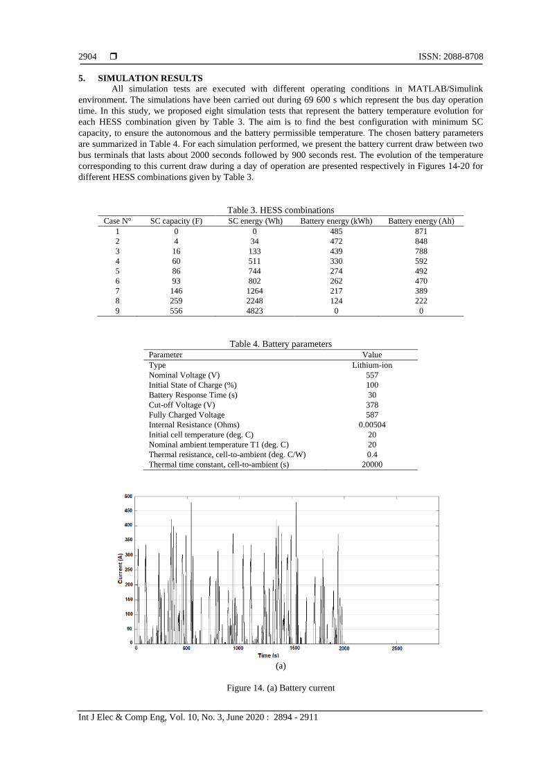
5. SIMULATION RESULTS
All simulation tests are executed with different operating conditions in MATLAB/Simulink
environment. The simulations have been carried out during 69 600 s which represent the bus day operation
time. In this study, we proposed eight simulation tests that represent the battery temperature evolution for
each HESS combination given by Table 3. The aim is to find the best configuration with minimum SC
capacity, to ensure the autonomous and the battery permissible temperature. The chosen battery parameters
are summarized in Table 4. For each simulation performed, we present the battery current draw between two
bus terminals that lasts about 2000 seconds followed by 900 seconds rest. The evolution of the temperature
corresponding to this current draw during a day of operation are presented respectively in Figures 14-20 for
different HESS combinations given by Table 3.
Table 3. HESS combinations
Case N° SC capacity (F) SC energy (Wh) Battery energy (kWh) Battery energy (Ah)
1 0 0 485 871
2 4 34 472 848
3 16 133 439 788
4 60 511 330 592
5 86 744 274 492
6 93 802 262 470
7 146 1264 217 389
8 259 2248 124 222
9 556 4823 0 0
Table 4. Battery parameters
Parameter Value
Type Lithium-ion
Nominal Voltage (V) 557
Initial State of Charge (%) 100
Battery Response Time (s) 30
Cut-off Voltage (V) 378
Fully Charged Voltage 587
Internal Resistance (Ohms) 0.00504
Initial cell temperature (deg. C) 20
Nominal ambient temperature T1 (deg. C) 20
Thermal resistance, cell-to-ambient (deg. C/W) 0.4
Thermal time constant, cell-to-ambient (s) 20000
(a)
Figure 14. (a) Battery current
Int J Elec & Comp Eng ISSN: 2088-8708
Hybrid energy storage system optimal sizing for urban electrical… (Si Mohamed Faresse)
2905
(b)
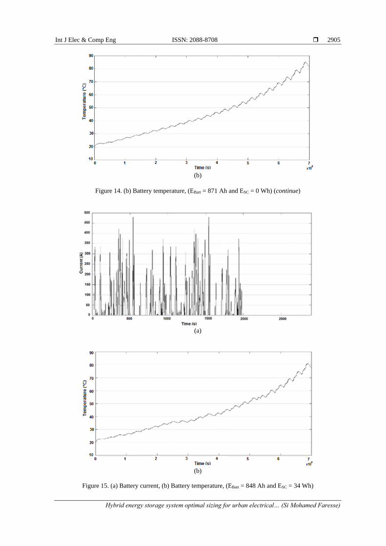
Figure 14. (b) Battery temperature, (EBatt = 871 Ah and ESC = 0 Wh) (continue)
(a)
(b)
Figure 15. (a) Battery current, (b) Battery temperature, (EBatt = 848 Ah and ESC = 34 Wh)
ISSN: 2088-8708
Int J Elec & Comp Eng, Vol. 10, No. 3, June 2020 : 2894 - 2911
2906
(a)
(b)
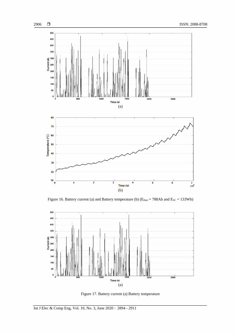
Figure 16. Battery current (a) and Battery temperature (b) (EBatt = 788Ah and ESC = 133Wh)
(a)
Figure 17. Battery current (a) Battery temperature
Int J Elec & Comp Eng ISSN: 2088-8708
Hybrid energy storage system optimal sizing for urban electrical… (Si Mohamed Faresse)
2907
(b)
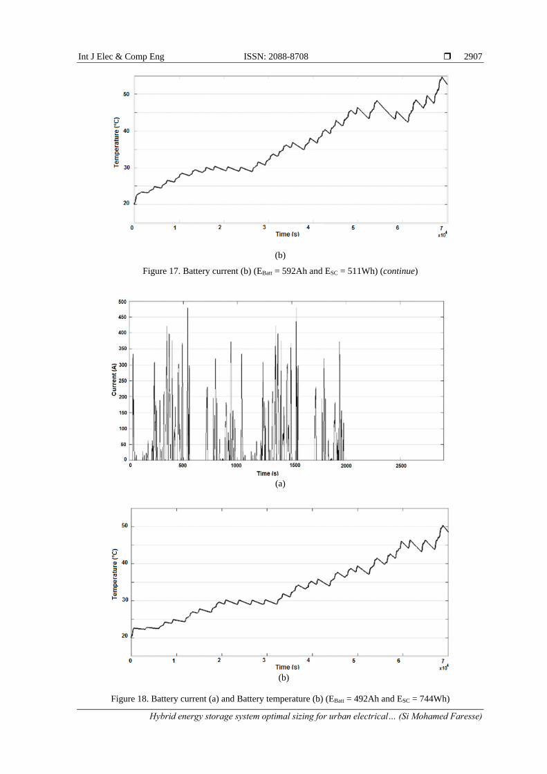
Figure 17. Battery current (b) (EBatt = 592Ah and ESC = 511Wh) (continue)
(a)
(b)
Figure 18. Battery current (a) and Battery temperature (b) (EBatt = 492Ah and ESC = 744Wh)
ISSN: 2088-8708
Int J Elec & Comp Eng, Vol. 10, No. 3, June 2020 : 2894 - 2911
2908
(a)
(b)
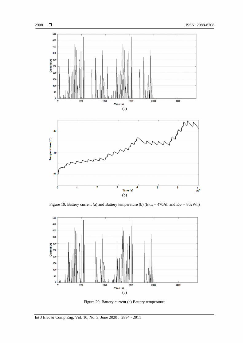
Figure 19. Battery current (a) and Battery temperature (b) (EBatt = 470Ah and ESC = 802Wh)
(a)
Figure 20. Battery current (a) Battery temperature
Int J Elec & Comp Eng ISSN: 2088-8708
Hybrid energy storage system optimal sizing for urban electrical… (Si Mohamed Faresse)
2909
(b)
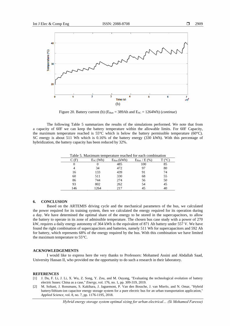
Figure 20. Battery current (b) (EBatt = 389Ah and ESC = 1264Wh) (continue)
The following Table 5 summarizes the results of the simulations performed. We note that from
a capacity of 60F we can keep the battery temperature within the allowable limits. For 60F Capacity,
the maximum temperature reached is 55°C which is below the battery permissible temperature (60°C).
SC energy is about 511 Wh which is 0.16% of the battery energy (330 kWh). With this percentage of
hybridization, the battery capacity has been reduced by 32%.
Table 5. Maximum temperature reached for each combination C (F) ESC (Wh) EBatt (kWh) EBatt / E (%) T (°C)
0 0 485 100 85
4 34 472 97 80
16 133 439 91 74
60 511 330 68 55
86 744 274 56 50
93 802 262 54 45
146 1264 217 45 40
6. CONCLUSION
Based on the ARTEMIS driving cycle and the mechanical parameters of the bus, we calculated
the power required for its training system, then we calculated the energy required for its operation during
a day. We have determined the optimal share of the energy to be stored in the supercapacitors, to allow
the battery to operate in its zone of admissible temperature. The chosen bus case study with a power of 270
kW, requires a daily energy autonomy of 364 kWh is the equivalent of 871 Ah battery under 557 V. We have
found the right combination of supercapacitors and batteries, namely 511 Wh for supercapacitors and 592 Ah
for battery, which represents 68% of the energy required by the bus. With this combination we have limited
the maximum temperature to 55°C.
ACKNOWLEDGEMENTS
I would like to express here the very thanks to Professors: Mohamed Assini and Abdallah Saad,
University Hassan II, who provided me the opportunity to do such a research in their laboratory.
REFERENCES [1] J. Du, F. Li, J. Li, X. Wu, Z. Song, Y. Zou, and M. Ouyang, "Evaluating the technological evolution of battery
electric buses: China as a case," Energy, vol. 176, no. 1, pp. 309-319, 2019.
[2] M. Soltani, J. Ronsmans, S. Kakihara, J. Jaguemont, P. Van den Bossche, J. van Mierlo, and N. Omar, "Hybrid
battery/lithium-ion capacitor energy storage system for a pure electric bus for an urban transportation application,"
Applied Science, vol. 8, no. 7, pp. 1176-1195, 2018.

ISSN: 2088-8708
Int J Elec & Comp Eng, Vol. 10, No. 3, June 2020 : 2894 - 2911
2910
[3] K. Jaewan, O. Jinwoo and L. Hoseong, "Review on battery thermal management system for electric vehicles,"
Applied Thermal Engineering, vol. 149, pp. 192-212, 2019.
[4] S. M. Faresse, M. Assini, and A. Saad, "Battery thermal behavior in hybrid energy storage unit
(battery/supercapacitor) for dynamic loads," International Journal of Scientific & Engineering Research, vol. 9,
no. 2, pp. 1439-1446, 2018.
[5] L. Kouchachvili, W. Yaïci, and E. Entchev, "Hybrid battery/supercapacitor energy storage system for the electric
vehicles," Journal of Power Sources, vol. 374, pp. 237-248, 2018.
[6] Z. Cabrane, M. Ouassaid, and M. Maaroufi, "Analysis and evaluation of battery-supercapacitor hybrid energy
storage system for photovoltaic installation," International Journal of Hydrogen Energy, vol. 41, no. 45,
pp. 20897-20907, 2016.
[7] J. Nájera, P. Moreno-Torres, M. Lafoz, R. M. de Castro, and J. R. Arribas, "Approach to hybrid energy storage
systems dimensioning for urban electric buses regarding efficiency and battery aging," Energies, vol. 10, no. 11,
pp. 1708-1724, 2017.
[8] W. Yusheng, H.Yongxi, X. Jiuping, and N. Barclay, "Optimal recharging scheduling for urban electric buses:
A case study in Davis," Transportation Research Part E, vol. 100, pp. 115–132, 2017.
[9] R. Xiong, H. Chen, C. Wang, and F. Sun, "Towards a smarter hybrid energy storage system based on battery and
ultracapacitor-a critical review on topology and energy management," Journal of Cleaner Production, vol. 202,
pp. 1228–1240, 2018.
[10] S. Zhang, R. Xiong, and X. Zhou, "Comparison of the topologies for a hybrid energy-storage system of electric
vehicles via a novel optimization method," SCIENCE CHINA-Technological Sciences, vol. 58, no. 7,
pp. 1173-1185, 2015.
[11] T. Zimmermann, P. Keil, M. Hofmann, M. F. Horsche, S. Pichlmaier, and A. Jossen, "Review of system topologies
for hybrid electrical energy storage systems," Journal of Energy Storage, vol. 8, pp. 78-90, 2016.
[12] X. Changle, W. Yanzi, H. Sideng and W. Weida, "A New Topology and Control Strategy for a Hybrid Battery-
Ultracapacitor Energy Storage System," Energies, vol. 7, pp. 2874-2896, 2014.
[13] S. Ziyou, L. Jianqiu, H. Xuebing, X. Liangfei, L. Languang, O. Minggao and H. Hofmann, "Multi-objective
optimization of a semi-active battery/supercapacitor energy storage system for electric vehicles," Applied Energy,
vol. 135, pp. 212–224, 2014.
[14] S. Ziyou, H. Hofmann, L. Jianqiu, H. Xuebing, and Z. Xiaowu, "A comparison study of different semi-active
hybrid energy storage system topologies for electric vehicles," Journal of Power Sources, vol. 274, pp. 400-411,
2015.
[15] S. Arrigoni, D. Tarsitano, and F. Cheli, "Comparison between different energy management algorithms for
an urban electric bus with hybrid energy storage system based on battery and supercapacitors," Int. J. Heavy
Vehicle Systems, vol. 23, no. 2, pp. 171-189, 2016.
[16] D. Tarsitano, L. Mazzola, F. Luigi Mapelli, S. Arrigoni, F. Cheli and F. Haskaraman, "On Board Energy
Management Algorithm Based on Fuzzy Logic for an Urban Electric Bus with Hybrid Energy Storage System,"
Advanced Microsystems for Automotive Applications, pp. 179-187, 2014.
[17] Y. Huilong, D. Tarsitano, H. Xiaosong, and F. Cheli, "Real time energy management strategy for a fast charging
electric urban bus powered by hybrid energy storage system," Energy, vol. 112, pp. 322–331, 2016.
[18] O. Tremblay and L. A. Dessaint, "Experimental validation of a battery dynamic model for EV applications," World
Electric Vehicle Journal, vol. 3, no. 2, pp. 289-298, 2009.
[19] L. H. Saw, K. Somasundaram, Y. Ye, and A.A.O. Tay, "Electro-thermal analysis of lithium iron phosphate battery
for electric vehicles," Journal of Power Sources, vol. 249, pp. 231–238, 2014.
[20] P. O. Logerais, M. A. Camara, O. Riou, A. Djellad, A. Omeiri, F. Delaleux, and J. F. Durastanti, "Modeling of
a supercapacitor with a multibranch circuit," International Journal of Hydrogen Energy, vol. 40, no. 39, pp. 13725-
13736, 2015.
[21] N. Xu and J. Riley, "Nonlinear analysis of a classical system: The double-layer capacitor," Electrochemistry
Communications, vol. 13, no. 10, pp. 1077–1081, 2011.
[22] S. N. Motapon, L. A. Dessaint, and K. Al-Haddad, "A comparative study of energy management schemes for
a fuel-cell hybrid emergency power system of more-electric aircraft," IEEE Transactions on industrial electronics,
vol. 61, no. 3, pp 1320-1334, 2014.
[23] M. Andre, R. Joumard, R. Vidon, P. Tassel, and P. Perret, "Real-world European driving cycles, for measuring
pollutant emissions from high- and low-powered cars," Atmospheric Environment, vol. 40, no. 31, pp. 5944-5953,
2006.
[24] W. Xiaogang, H. Weixiang, and S. Zhibin, "Research on energy management of hybrid energy storage system for
electric bus," Advances in Mechanical Engineering, vol. 9, no. 10, pp. 1-13, 2017.
[25] B. Tabbache, S. Djebarri, A. Kheloui, M. Benbouzid, "A Power Presizing Methodology for Electric Vehicle
Traction Motors," International Review on Modelling and Simulations, vol. 6, pp. 29-32, 2013.
[26] X. Xin and C. Zhang, "Optimal Design of Electric Vehicle Power System with the Principle of Minimum Curb
Mass," Energy Procedia, vol. 105, pp. 2629 – 2634, 2017.
Int J Elec & Comp Eng ISSN: 2088-8708
Hybrid energy storage system optimal sizing for urban electrical… (Si Mohamed Faresse)
2911
BIOGRAPHIES OF AUTHORS
Si Mohamed Faresse is a Ph.D. student at the National Higher School of Electricity and Mechanics,
Laboratory of Electrical Systems and Energy, University Hassan II of Casablanca–Morocco.
His research interests include hybrid energy storage system for transport and photovoltaic
applications.
Mohamed Assini, Ph. D., Professor at the Department of Electrical Engineering, National Higher
School of Electricity and Mechanics, University Hassan II of Casablanca, Morocco. His research
interests include hybrid energy storage system for transport and photovoltaic applications,
Renewable Energies and static converters.
Abdallah Saad, Ph. D., Professor at the Department of Electrical Engineering, National Higher
School of Electricity and Mechanics, University Hassan II of Casablanca, Morocco. His research
interests include hybrid energy storage system for transport and photovoltaic applications, electricity
network and Facts, Renewable Energies and smart grids.