hybrid manufacturing: integrating direct write and stereolithography
TRANSCRIPT
HYBRID MANUFACTURING: INTEGRATING DIRECT WRITE AND STEREOLITHOGRAPHY
Frank Medina*, Amit Lopes*, Asim Inamdar*, Robert Hennessey*, Jeremy Palmer**, Bart
Chavez**, Don Davis**, Phil Gallegos**, Ryan Wicker* *University of Texas at El Paso, W.M. Keck Border Biomedical Manufacturing and Engineering Laboratory, Department of Mechanical and Industrial Engineering, El Paso, Texas 79968-0521
**Sandia National Laboratories, Albuquerque, NM, 87185-0958 Reviewed, accepted August 23, 2005
Abstract A commercial stereolithography (SL) machine was modified to integrate fluid dispensing or
direct-write (DW) technology with SL in an integrated manufacturing environment for automated and efficient hybrid manufacturing of complex electrical devices, combining three-dimensional (3D) electrical circuitry with SL-manufactured parts. The modified SL system operates similarly to a commercially available machine, although build interrupts were used to stop and start the SL build while depositing fluid using the DW system. An additional linear encoder was attached to the SL platform z-stage and used to maintain accurate part registration during the SL and DW build processes. Individual STL files were required as part of the manufacturing process plan. The DW system employed a three-axis translation mechanism that was integrated with the commercial SL machine. Registration between the SL part, SL laser and the DW nozzle was maintained through the use of 0.025-inch diameter cylindrical reference holes manufactured in the part during SL. After depositing conductive ink using DW, the SL laser was commanded to trace the profile until the ink was cured. The current system allows for easy exchange between SL and DW in order to manufacture fully functional 3D electrical circuits and structures in a semi-automated environment. To demonstrate the manufacturing capabilities, the hybrid SL/DW setup was used to make a simple multi-layer SL part with embedded circuitry. This hybrid system is not intended to function as a commercial system, it is intended for experimental demonstration only. This hybrid SL/DW system has the potential for manufacturing fully functional electromechanical devices that are more compact, less expensive, and more reliable than their conventional predecessors, and work is ongoing in order to fully automate the current system. Keywords: rapid prototyping; stereolithography; direct-write; hybrid manufacturing; functional integrated layered manufacturing
Introduction Rapid prototyping (RP) technologies such as solid freeform fabrication (SFF), layered
manufacturing (LM), and other similar technologies enable the manufacture of complex three-dimensional (3D) parts. Stereolithography (SL) is one of the most widely used RP technologies known around the world. The resolution of SL machines and the ability of SL to manufacture highly complex 3D objects allow SL to build both functional and non-functional prototypes. The materials’ development for SL and other RP technologies has been primarily focused on improving the mechanical strength, durability, and thermal property characteristics of RP materials. As a result of these improvements, there is great interest in expanding the markets for RP into many areas such as rapid manufacturing of fully functional electromechanical devices.
39

In an attempt to assist in expanding the markets for RP into rapid manufacturing, researchers at the UTEP W.M. Keck Border Biomedical Manufacturing and Engineering Laboratory and Sandia National Laboratories have developed a hybrid manufacturing setup. This setup provides an integrated manufacturing environment where SL is employed in conjunction with direct write (DW) fluid dispensing technology to capitalize on each of the individual process capabilities for developing unique electromechanical devices. The hybrid SL/DW machine offers enormous potential in integrated manufacturing of unique electromechanical devices by removing many of the complex shape manufacturing limitations experienced by conventional manufacturing processes. Recent breakthroughs in DW ink dispensing for military applications have made this technology attractive for manufacturing complex 3D, multi-layered, high density, integrated, and fully functional electromechanical systems (Church et al., 2000). These electromechanical systems are more compact, less expensive, and more reliable than their conventional predecessors. Process development issues include improvements in STL file generation, integration of curable media such as DW conductive inks with SL technologies without contamination, adhesion of the ink and SL resin, and curing of the conductive ink. Although there have been improvements in writing capabilities, many available SL resins are incompatible with the high temperatures required to cure DW inks (typically above 100°C). Recent developments in high temperature resins such as DSM Somos® ProtoToolTM, ProtoThermTM, and NanoFormTM resins have enabled the integration of DW with SL technologies.
In recent years, researchers have developed systems for automatic dispensing of conductive, thermally curable media, such as DW inks for maskless patterning of electronics. Lewis and Gratson (2004) listed several applications of robotic dispensing systems for creating 3D arrays of many fluidic matrices. Ang et al. (2002) used a robotic dispensing system for manufacturing 3D scaffolds. Im et al. (2002) proposed the concept of functional prototype development to overcome the limitations of mono-material and mono-functions of conventional RP systems. Kataria and Rosen (2004) demonstrated a start and stop process to embed functional inserts using SL. Palmer et al. (2004) proposed a new manufacturing process to integrate SL and DW technologies for the fabrication of 3D, high-density circuitry. The work of Palmer et al. (2004) demonstrated the feasibility of rapidly manufactured, integrated, and functional electromechanical systems that are arguably more compact, less expensive, and reliable than the traditional systems by combining DW and SL in separate processes. Medina et al. (2005) further demonstrated the integration of separate DW and SL systems to incorporate a video camera in a commercial clock for a home security application. Some of the build issues encountered during the work of Palmer et al. (2004) and Medina et al. (2005) include the re-registration, continuous cleaning, and curing of the part during the build process. After the SL part was built, it was removed from the SL machine, cleaned, and cured to perform the DW process. Once the DW process was completed, the part needed to be re-registered to the SL platform before continuing the build to encapsulate the circuitry (Palmer et al., 2004; Medina et al., 2005). These two previous efforts motivated the development of an automated manufacturing environment that combines SL and DW.
The current effort represents the continuing evolution of the Functional Integrated Layered Manufacturing (FILM) concept introduced in the work of Medina et al. (2005) where RP is employed in conjunction with automated access to a toolbox of additional manufacturing technologies to capitalize on individual process capabilities for developing unique functional devices. As the next step in this development, this work presents a hybrid SL/DW machine setup for rapid development of circuitry to manufacture more compact electromechanical components
40

in a semi-automated environment. The hybrid system provides a method for automated deposition of fluid media during the SL build (by stopping the SL build but not removing the part from the SL machine), automated curing of the media using the SL laser and continued building without the need for recalibration and intermediate washing or resin curing. An additional linear encoder attached to the SL z-stage was used to maintain part registration during the interrupted build processes. The DW system employed a three-axis translation mechanism that was integrated with the commercial SL machine. Registration between the SL part, SL laser and the DW nozzle was maintained through the use of .025-inch reference holes manufactured in the part using SL. The current system allows for easy exchange between SL and DW in order to manufacture fully functional 3D electrical circuits and structures in a semi-automated environment. To demonstrate the manufacturing capabilities, the hybrid setup was used to make a simple multi-layer SL part with embedded circuitry. The following describes the design and demonstration of the semi-automated hybrid SL/DW machine.
Hybrid stereolithography/direct-write machine setup The hybrid SL/DW manufacturing setup offers an integrated RP system comprising a
traditional SL apparatus and DW fluid dispensing system as depicted in Figure 1. The SL 250/50 machine manufactured by 3D systems was used with a 355 nm solid-state laser upgrade (Series 3500-SMPS, DPSS Lasers Inc., Santa Clara, CA). DSM Somos® ProtoThermTM 12120 was selected as the resin for this work due to its ability to withstand temperatures (HDT) up to 126 ˚C and relatively low viscosity (550 centipoise, cps at 30 ˚C) (DSM Somos®, New Castle, Delaware). One of the issues encountered in the work of Palmer et al. (2004) was the difficult handling and building characteristics of ProtoToolTM associated with the materials high value of viscosity (2500 cps). The low material viscosity of ProtoThermTM facilitated improved handling, building without sweeping, and cleaning prior to DW deposits.
DPSS solid state laser
system
3D Systems 250/50 SL machine
DW dispensing syringe and
nozzle
UV shield
Translation stage
controller
Dispensing system console
3-axis translation
stage
Adjustable height mobile
workbench
Figure 1. The hybrid SL/DW machine setup.
41

The DW setup was placed on a custom-made, adjustable height table. The table consisted of a stainless steel top and an adjustable-height hand-crank two legged mobile workbench (Part # 9054T113 and Part # 3517T82, respectively, McMaster-Carr Supply Company, Chicago, IL). Two support plates were welded to the stainless steel table top which was then bolted to the workbench base using standard fasteners. The table was redesigned to incorporate two 3/8 in. dowel pins that matched 3/8 in. holes drilled in the rim support plate of the SL machine using a hand drill as shown in Figure 2a. Alignment was achieved by inserting the dowel pins in the matching holes in the rim support plate until both pins touched the rim, illustrated in Figure 2b. The X-Y axis movement of the DW dispensing nozzle was provided by two automatic linear stages each 3-feet long with 40 thread/inch lead screws (Type M062-LS09, 200 steps/rev, Velmex Inc., Bloomfield, NY), arranged perpendicular to each other using support plates. An additional manual linear stage (Model # MA4012P40-S4-0, Velmex Inc., Bloomfield, NY) with an 8-inch traverse distance and 40 thread/inch lead screw was used for Z-axis movement as well as for supporting the tip of the DW ink dispensing system. The X, Y, and Z stages of the DW system facilitated movement of the fluid dispensing system, enabling precise fluid placement without intermediate calibration or removal of the SL part. An additional z-stage linear encoder (LS 303, Heidenhain Corporation, Schaumburg, Illinois) was used to maintain part registration during build interrupts required for incorporating the DW process.
Rim support plate with holes to receive dowel
pins
X-Y translation
stage
Alignment dowel pins
Alignment dowel pins
Z traverse system w/dispensing tip holder
(a) (b) Figure 2. (a) The 3-axes traverse system, (b) alignment of the SL/DW system.
The 2405 Ultra Dispensing System (EFD Inc., East Providence, Rhode Island) shown in
Figure 3 was integrated with the SL machine and adapted to deposit fluid such as conductive ink on the part manufactured by the SL machine. It consisted of an air pressure control console and a dispensing syringe and tip (with nozzle diameters down to 6 mils), which was connected to the console with a plastic hose. The console obtains an externally supplied inlet air pressure (up to 100 psi) and regulates the outlet pressure (from 0 – 5 psi), which was then supplied to the dispensing tip. The ink can be dispensed manually or controlled using LabVIEW® to draw given circuit profiles. It may be adapted to dispense a variety of fluids including conductive inks and virtually any other fluid. For this work, a conductive ink (CI-1002, ECM, Delaware, Ohio) was dispensed on ProtoThermTM 12120 resin (DSM Somos®, New Castle, Delaware). The ink used here was selected based on its low cost ($ 0.50/gm), low curing temperature (110 ˚C for 2 hours using 15 minute intervals), and low resistivity (0.035 Ω/square-mil) (ECM LLC, Delaware, Ohio). The traverses as well as the dispensing system were controlled using a separate computer with LabVIEW®.
42

Dispensing syringe
Dispensing nozzle
EFD 2405 Ultra Dispensing
System console
Figure 3. The DW Ultra Dispensing System.
A preliminary ink dispensing experiment using several dispensing tips at varying dispensing
pressures aided in determining the dispensing tip and pressure selection used here and the results are shown in Figure 4. The size of the dispensing tip and the dispensing pressure were the most important parameters which determined the line width of the circuitry for a given Z distance (distance between the dispensing tip and the SL part) of 5 mils and traverse speed of 0.0625 in/sec. The selected speed was recommended by the traverse manufacturer for the type of lead screw that was used in the experimental setup. Also, this speed was selected because it was the fastest speed at which the traverse did not skip while producing a uniform ink line. The cost (up $300k) of faster (> 7 in/sec) and more precise DW systems prevented the use of those systems in the experimental setup. As stated earlier, this system is not intended to function as a commercial system, it is meant for experimental demonstration only. The dispensing tips ranged in size from 6 to 16-mils while the dispensing pressures ranged from 1 to 5 psi. The 6 mil, 10 mil, and 13 mil dispensing
0
0.01
0.02
0.03
0.04
0.05
0.06
0.07
0.08
0 1 2 3 4 5 6
Dispensing Pressure (psi)
Line
Wid
th (i
nche
s)
6-mil tip10-mil tip13-mil tip16-mil tip
Selected dispensing parameters
Figure 4. Line width versus dispensing pressure for different size injection tips (0.0625 in/sec traverse speed and 5-mil distance between tip and surface).
43

tips provided discontinuous lines below 3, 2, and 1 psi dispensing pressures, respectively (Figure 4 illustrates results for continuous lines only). The experimental results indicate that the combination of the 6-mil dispensing tip and a dispensing pressure of 4 psi provided the narrowest uniform line (0.014”), and these operating conditions were selected for the work presented here.
Hybrid SL/DW machine operation overview
In order to integrate SL and DW, the standard operation of SL was modified. Figure 5 provides a sample part with embedded electrical circuitry, vertical interconnection between the DW circuitry, and multiple SL builds that encapsulate the circuitry. This figure is intended to provide a general description of the operation of the hybrid SL/DW system. The figure represents building two separate SL parts (each with multiple layers), two separate DW electrical traces, and a vertical interconnection between the two circuit traces (providing 3D circuitry). The key elements of successful operation include being able to accurately register the DW trace with the SL laser (since the SL laser is used to cure the ink) and providing vertical electrical interconnections. The registration issue is solved by using a small cylindrical hole manufactured during the SL build that is used to register the DW ink dispensing tip to the SL part. The SL vat is lowered to its lowest available z-height when using DW so that the platform can remain at the same z-height. With the platform remaining at the same height, there are no geometric differences between the DW trace and the SL laser trace when curing the DW ink. To provide vertical interconnection, the reference hole (or other holes placed in the SL part) is incrementally filled with conductive ink and cured using the SL laser. These features summarize the necessary elements for successful hybrid SL/DW operation. Additional details of the operation are provided below in the description of part manufacture illustrated in Figure 5.
Figure 5 represents a simple part with embedded circuitry to be manufactured using the hybrid SL/DW setup. The SL laser is used to cure the conductive ink which is dispensed during the DW process. The laser curing process creates a continuous manufacturing scenario with the
Figure 5. The hybrid SL/DW operation.
Reference hole for DW
Vertical interconnect
STL part to cure the ink for vertical interconnects (4th part)
Hole to test 3D
connectivity
The base (1st part)
First DW layer profile (2nd part)
Build section for encapsulating DW circuitry
(3rd part)
Second DW layer profile
(5th part)
44
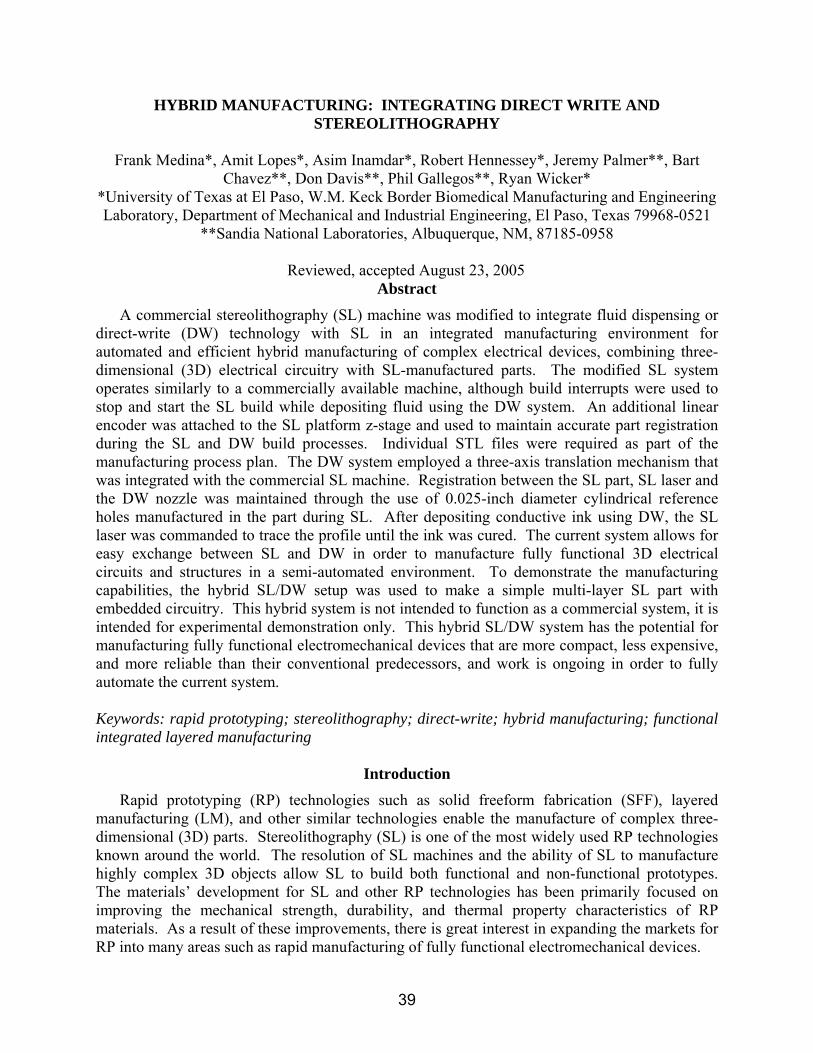
potential to manufacture fully functional electromechanical components. Laser curing permits the build to continue without removing the part from the platform. The hybrid setup thus addresses the manufacturing issues like part re-registration, continuous cleaning, and curing between part builds, as mentioned in Medina et al. (2005). SolidWorks modeling software or similar CAD packages can be used to generate the individual part designs, and converted into STL file format as required. 3D Systems proprietary slicing software, 3D Lightyear™ 1.4, is used to convert the STL files generated during the part preparation and design stages into the build file format required for the operation of the SL 250/50.
The entire build process is designed in the form of an assembly using SolidWorks software. The assembly is first saved as a part file and then converted into an STL file. The final STL file should be divided into five distinct parts, as shown in Figure 5, to facilitate the SL/DW integration. The first STL part is the base on which the first DW circuit is drawn. This base features a reference hole which facilitates the initial calibration of the ink dispensing tip to the SL part. Traditional SL part building is performed layer by layer with planned interruptions to incorporate the DW process. Once the individual SL build is complete, the vat is lowered, while maintaining the build platform position constant to expose the top surface. The top surface can then be cleaned using cleaning paper dipped in alcohol. The top surface is further optionally cured using the laser to ensure no contamination between the resin and the ink. The DW system is then used to dispense the conductive ink.
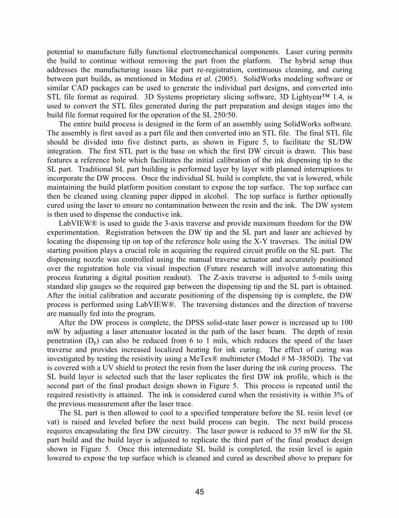
LabVIEW® is used to guide the 3-axis traverse and provide maximum freedom for the DW experimentation. Registration between the DW tip and the SL part and laser are achieved by locating the dispensing tip on top of the reference hole using the X-Y traverses. The initial DW starting position plays a crucial role in acquiring the required circuit profile on the SL part. The dispensing nozzle was controlled using the manual traverse actuator and accurately positioned over the registration hole via visual inspection (Future research will involve automating this process featuring a digital position readout). The Z-axis traverse is adjusted to 5-mils using standard slip gauges so the required gap between the dispensing tip and the SL part is obtained. After the initial calibration and accurate positioning of the dispensing tip is complete, the DW process is performed using LabVIEW®. The traversing distances and the direction of traverse are manually fed into the program.
After the DW process is complete, the DPSS solid-state laser power is increased up to 100 mW by adjusting a laser attenuator located in the path of the laser beam. The depth of resin penetration (Dp) can also be reduced from 6 to 1 mils, which reduces the speed of the laser traverse and provides increased localized heating for ink curing. The effect of curing was investigated by testing the resistivity using a MeTex® multimeter (Model # M–3850D). The vat is covered with a UV shield to protect the resin from the laser during the ink curing process. The SL build layer is selected such that the laser replicates the first DW ink profile, which is the second part of the final product design shown in Figure 5. This process is repeated until the required resistivity is attained. The ink is considered cured when the resistivity is within 3% of the previous measurement after the laser trace.
The SL part is then allowed to cool to a specified temperature before the SL resin level (or vat) is raised and leveled before the next build process can begin. The next build process requires encapsulating the first DW circuitry. The laser power is reduced to 35 mW for the SL part build and the build layer is adjusted to replicate the third part of the final product design shown in Figure 5. Once this intermediate SL build is completed, the resin level is again lowered to expose the top surface which is cleaned and cured as described above to prepare for
45

the next DW process. The reference hole on the third part of the SL build is filled with ink to provide a vertical connection between the two circuits. The laser power is again increased up to 100 mW to cure the ink. The hole is filled with ink one layer at a time and cured using the laser. These processes are continued until the desired SL/DW part is completed.
Fabrication demonstration
In order to demonstrate fabrication with the hybrid SL/DW system, a sample part was manufactured using DSM Somos® ProtoThermTM resin and the CI 1002 conductive ink according to the first 3 layers depicted in Figure 5. The SL/DW process was initiated by building the SL base with the reference hole. Once the first SL part was complete, the vat was lowered to expose the top surface, which was cleaned using paper dipped in alcohol. The top surface was further cured using the laser to prevent contamination between the resin and the ink. The 2405 Ultra Dispensing System was then aligned as described previously and used to dispense the conductive ink. LabVIEW® was used to guide the custom designed traverse system as well as control the dispensing for the DW experimentation.
(a) (b)
1 inch
Figure 6. (a) The traverse system for DW, (b) DW circuit profile Figure 6a shows the hybrid SL/DW system with particular emphasis on the three-axis
traverse mechanism used to guide the DW system. The SL part build was interrupted at the required layer and the DW ink dispensing system was aligned using the reference hole and commanded to deposit the circuitry as shown in Figure 6b. The integrated system was used to build circuitry without part removal or additional calibration. The traverses were controlled using LabVIEW® to replicate the required DW profile and dispense the ink to complete the circuitry as shown in Figure 7a.
After fluid deposition was complete, the ink was cured with the DPSS solid-state laser (the same laser used to perform SL) as shown in Figure 7b. Figure 8a shows an image of the cured ink. To test the effectiveness of the laser for ink curing, ink was deposited on a ProtoThermTM test piece and placed in a heat convection oven at 110 ˚C. The resistivity of the ink was monitored and recorded at 15 min intervals. The resistivity value recommended by the ink manufacturer was 0.035 Ω/square-mil. It was found that the laser curing process (10 traces at 3 minutes and 40 seconds per trace or 37 total minutes and 100 mW laser power) produced a resistivity value (0.05 Ω/square-mil), which was closer to the recommended value than could be obtained using the convection oven (0.09 Ω /square-mil) (2 hours at 110˚C). After completing the ink curing process, the integrated system leveled the vat and began traditional SL part
46

Laser curing the ink
(a) (b) Figure 7. (a) The direct write process, (b) laser curing of the conductive ink.
building on the part. The part was then reregistered to the building platform by adjusting the Z-height to allow the process to be continued at the next known layer using the z-stage linear encoder (LS 303, Heidenhain Corporation, Schaumburg, Illinois). This was done by selecting a specific start and end layer of the build file. The remaining part was completed to encapsulate the DW circuitry using the second part of the STL file as discussed earlier. The finished part, as shown in Figure 8b, features the vertical interconnect hole and the access hole used to test 3D conductivity. The total time for manufacturing the completed part with embedded circuitry and 3D connectivity was approximately 4 hours. Work is ongoing to compare this hybrid method with traditional methods that are currently used to build electromechanical systems. The surface layer circuitry resides on the top layer of the part while the remaining circuitry is embedded within the part.
Vertical interconnect
Access hole to embedded
circuitry
Surface layer circuitry
(a) (b) Figure 8. (a) Image of the cured ink, (b) finished part.
Conclusions
A hybrid SL/DW machine was developed for integrating SL and DW ink dispensing technology. A commercial SL machine was modified to integrate fluid dispensing or DW technology with SL in an integrated manufacturing environment for automated and efficient hybrid manufacturing of complex electrical devices. The modified SL system operates similarly to a commercially available machine, although build interrupts were used to stop and start the SL build while depositing fluid with the DW system. An additional linear encoder was connected to
47

the SL platform z-stage and used to maintain accurate part registration during the SL and DW build processes. The DW system featured a three-axis translation mechanism that was integrated with the commercial SL machine. The current system allows the exchange between SL and DW in order to manufacture fully functional 3D electrical circuits and structures in a semi-automated environment.
The hybrid SL/DW machine was used to manufacture a simple part featuring embedded circuitry. This work demonstrated the use of the SL laser to cure the conductive ink deposited using DW. This curing strategy enabled the build to continue without removing the part from the SL platform, maintaining accurate registration of the part within the SL machine. It was found that the laser curing process (37 minutes total laser trace time at 100 mW) produced a resistivity value (0.05 Ω/square-mil) closer to the recommended value than the convection oven curing (0.09 Ω /square-mil) (2 hours at 110˚C). A simple strategy using reference holes manufactured during SL was successfully demonstrated for registration of the DW dispensing tip with the SL part. Vertical interconnectivity was demonstrated by filling the reference hole or other holes in the SL part with the conductive ink and using the SL laser to cure the ink. The hybrid SL/DW manufacturing setup has potential for manufacturing fully functional electromechanical components in an automated build sequence, and work is ongoing to fully automate the manufacturing process.
Acknowledgments The research presented here was performed at UTEP in the W.M. Keck Border Biomedical
Manufacturing and Engineering Laboratory using equipment purchased through Grant Number 11804 from the W.M. Keck Foundation. This material is based in part upon work supported by the Texas Advanced Research (Advanced Technology/Technology Development and Transfer) Program under Grant Number 003661-0020-2003. Support was also provided through the Mr. and Mrs. MacIntosh Murchison Chair I in Engineering and through research contract 28643 from Sandia National Laboratories in the Laboratory Directed Research and Development (LDRD) program. Sandia National Laboratories is a multi-program laboratory operated by Sandia Corporation, a Lockheed Martin Company, for the United States Department of Energy’s National Nuclear Security Administration under contract DE-AC04-94AL85000.
References
1. T.H. Ang, F.S.A. Sultana, D.W. Hutmacher, Y.S. Wong, J.Y.H. Fuh, X.M. Mo, H.T. Loh, E. Burdet, and S.H. Teoh, “Fabrication of 3D Chitosan–Hydroxyapatite Scaffolds using a Robotic Dispensing System,” Materials Science and Engineering, Volume C 20, 2002, pages 35–42.
2. K.H. Church, C. Fore, and T. Feeley, “Commercial Applications and Review for Direct Write Technologies,” Materials Development for Direct Write Technologies, San Francisco, CA, April 24-26, Volume 624, pages 3-8, 2000.
3. DSM Somos, June 2002, ProtoTherm 12120 –Product Data Sheet, New Castle: Delaware, www.dsmsomos.com, 03/27/2005.
4. ECM LLC, 2004, CI-1002 – Product Data Sheet, Delaware, Ohio, www.conductives.com, 06/15/2005.
5. Y.G. Im, S.I. Chung, J.H. Son, Y.D. Jung, J.G. Jo, and H.D. Jeong, “Functional Prototype Development: Inner Visible Multi-Color Prototype Fabrication Process using
48

Stereolithography,” Journal of Materials Processing Technology, Volume 130-131, 2002, pages 372-377.
6. A. Kataria and D.W. Rosen, “Building Around Inserts: Methods for Fabricating Complex Devices in Stereolithography,” Rapid Prototyping Journal, Volume 7, Number 5, 2001, pages 253-261.
7. J. A. Lewis and G. M. Gratson, “Direct Writing in Three Dimensions,” Materials Today, Volume 7, Issues 7-8, July-August 2004, pages 32-39.
8. F. Medina, A.J. Lopes, A.V. Inamdar, R. Hennessey, J.A. Palmer, B.D. Chavez, and R.B. Wicker, “Integrating Multiple Rapid Manufacturing Technologies for Developing Advanced Customized Functional Devices,” Rapid Prototyping & Manufacturing 2005 Conference Proceedings, Rapid Prototyping Association of the Society of Manufacturing Engineers, May 10-12, 2005, Hyatt Regency Dearborn, Michigan.
9. J.A. Palmer, P. Yang, D.W. Davis, B.D.Chavez, P.L.Gallegos, R.B. Wicker, and F.R. Medina, “Rapid Prototyping of High Density Circuitry,” Rapid Prototyping & Manufacturing 2004 Conference Proceedings, Rapid Prototyping Association of the Society of Manufacturing Engineers, May 10-13, 2004, Hyatt Regency Dearborn, Michigan. Also, SME Technical Paper TP04PUB221 (Dearborn, Michigan: Society of Manufacturing Engineers, 2004).
10. J.A. Palmer, J.L. Summers, D.W. Davis, P.L. Gallegos, B.D. Chavez, P. Yang, F. Medina, and R.B. Wicker, “Realizing 3-D Interconnected Direct Write Electronics within Smart Stereolithography Structures,” International Mechanical Engineering Congress and Exposition 2005 Proceedings, November 14-18, 2005, Orlando, Florida, to appear.
49