hydra i data display systemthe hydra i data display system was one of four display processing...
TRANSCRIPT
LOAN COPY: RETURN TO
KIRTLAND AFB, N MEX AFWL (WLIL-2)
, -
HYDRA I DATA DISPLAY SYSTEM
by Roger L. Hodgkins und Donuld R. Osgood
Munned Spucecruft Center Houston, Texas
NATIONAL AERONAUTICS AND SPACE ADMINISTRATION WASHINGTON, D. C. MAY 1968
https://ntrs.nasa.gov/search.jsp?R=19680015530 2020-05-23T21:06:59+00:00Z
TECH LIBRARY KAFB, NM
HYDRA I DATA DISPLAY SYSTEM
By Roger L. Hodgkins and Donald R. Osgood
Manned Spacecraft Center Houston, Texas
NATIONAL AERONAUTICS AND SPACE ADMINISTRATION
For s o l e by the Clearinghouse for Federal Scientific and Technicol lnformotion Springfield, Virginia 22151 - CFSTI price $3.00
ABSTRACT
The Hydra I is an extremely flexible and versa- tile data display system in which a television monitor sc reen se rves as a working surface upon which an operator can develop, o r create, graphic displays such as written documents, char ts , diagrams, graphs, background slides, and other graphic art through the use of special control keyboards and operating tech- niques. An operator can create, rearrange, delete, or add to the graphic display to develop any desired format. Upon completion of a graphic display, it can be recorded in a magnetic-tape l ibrary, plotted on an X-Y plotter, recorded as a punched paper tape, o r r e - corded as a f r ame of a sequential-playback magnetic tape. Displays recorded in the magnetic-tape l ibrary can be recalled for examination o r revision.
ii
I
HYDRA I DATA DISPLAY SYSTEM
By Roger L. Hodgkins and Donald R. Osgood Manned Spacecraft Center
SUMMARY
This document outlines and descr ibes the Hydra I data display system and the components, functional qualities, and various operational techniques for the purpose of disclosing the technical potential of the control concepts embodied in the system. The Hydra I uses a television monitor sc reen as a working surface upon which an oper- a tor can develop, o r create, graphic displays such as written documents, charts, dia- grams, background slides, and other graphic art. The graphic display can be recorded in a magnetic-tape l ibrary, plotted on an X-Y plotter, recorded as a punched paper tape, o r recorded as a f rame of a sequential-playback magnetic tape. The concepts incorporated into the Hydra I system are of lasting interest to the information system designer.
INTRODUCTION
1 The Hydra I data display system was one of four display processing projects originally considered by the Data Systems Development Branch of the Information Sys- tems Division (ISD) of the NASA Manned Spacecraft Center. for development to the exclusion of the other three systems because it could f i l l such a wide variety of definite needs. It could serve as a developmental study into computer- aided graphical generation and associated graphical-data problems. Of special interest were operating controls, tutorial dialog between the computer and the human operator, and the storage and retr ieval of graphical displays developed on a volatile medium such as television. After the basic hardware had been fabricated and assembled, programs were developed incorporating the design philosophy worked out in preliminary studies and several earlier automatic checkout systems. It was at this point that the Hydra I concepts first began to verify the conclusions of the preliminary design studies. The system was used to assist the analysts in programing. of the system were developed first, and the keyboard-controlled and display-oriented
The Hydra I was chosen
The online programing sections
~
'In Greek mythology, Hydra was a serpentine monster with many heads. When one of the heads was severed f rom its body, it grew two heads to replace the lost one. The name is particularly apt. Even when discontinued, the Hydra I system had already been t ransferred to two other computer-display systems. The current Hydra has more "heads" than the original.
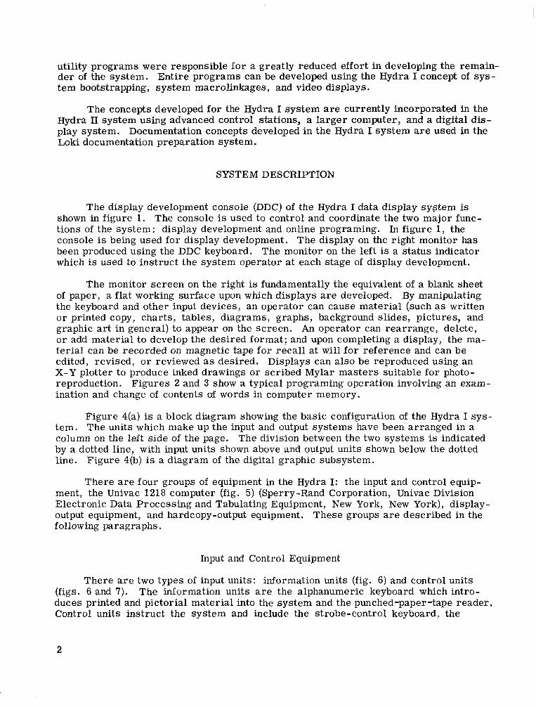
utility programs were responsible fo r a greatly reduced effort in developing the remain- de r of the system. Entire programs can be developed using the Hydra I concept of sys- tem bootstrapping, system macrolinkages, and video displays.
The concepts developed fo r the Hydra I system are currently incorporated in the Hydra I1 system using advanced control stations, a la rger computer, and a digital dis- play system. Documentation concepts developed in the Hydra I system are used in the Loki documentation preparation system.
SYSTEM DESCRIPTION
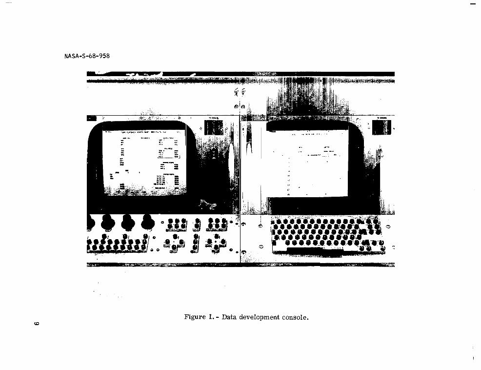
The display development console (DDC) of the Hydra I data display system is shown in figure 1. The console is used to control and coordinate the two major func- tions of the system: display development and online programing. In figure 1, the console is being used for display development. The display on the right monitor has been produced using the DDC keyboard. The monitor on the left is a status indicator which is used to instruct the system operator at each stage of display development.
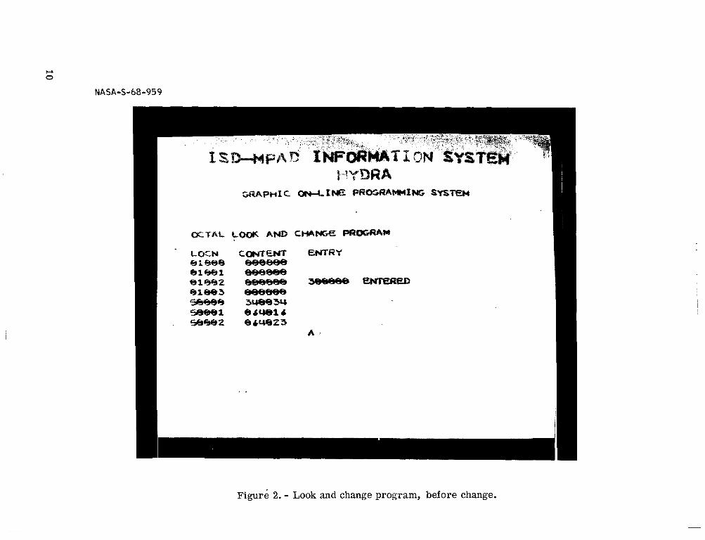
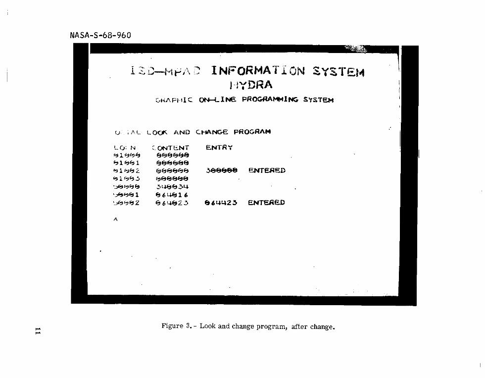
The monitor sc reen on the right is fundamentally the equivalent of a blank sheet of paper, a flat working surface upon which displays a r e developed. By manipulating the keyboard and other input devices, an operator can cause mater ia l (such as written o r printed copy, char ts , tables, diagrams, graphs, background slides, pictures, and graphic art in general) to appear on the screen. An operator can rearrange, delete, o r add material to develop the desired format; and upon completing a display, the ma- ter ia l can be recorded on magnetic tape fo r recal l at will for reference and can be edited, revised, o r reviewed as desired. Displays can also be reproduced using an X-Y plotter to produce inked drawings o r scribed Mylar mas ters suitable for photo- reproduction. ination and change of contents of words in computer memory.
Figures 2 and 3 show a typical programing operation involving an exam-
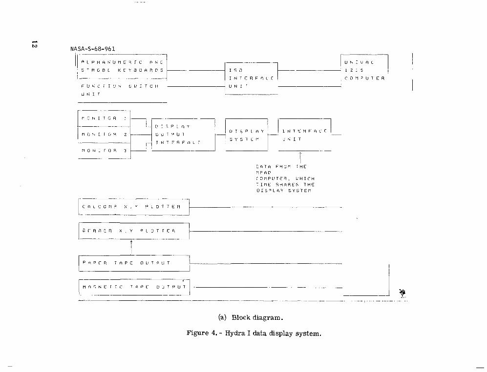
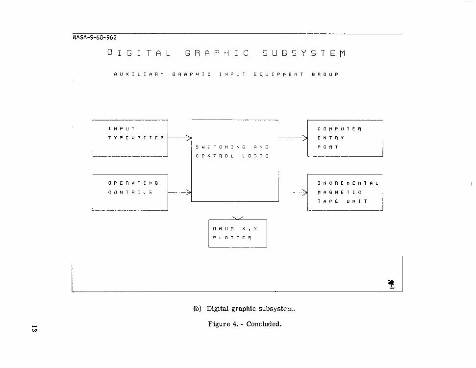
Figure 4(a) is a block diagram showing the basic configuration of the Hydra I sys- tem. The units which make up the input and output systems have been arranged in a column on the left side of the page. The division between the two systems is indicated by a dotted line, with input units shown above and output units shown below the dotted line. Figure 4(b) is a diagram of the digital graphic subsystem.
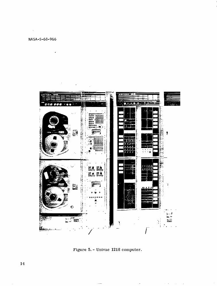
There are four groups of equipment in the Hydra I: the input and control equip- ment, the Univac 1218 computer (fig. 5) (Sperry-Rand Corporation, Univac Division Electronic Data Processing and Tabulating Equipment, New York, New York), display- output equipment, and hardcopy-output equipment. following paragraphs.
These groups are described in the
Input and Control Equipment
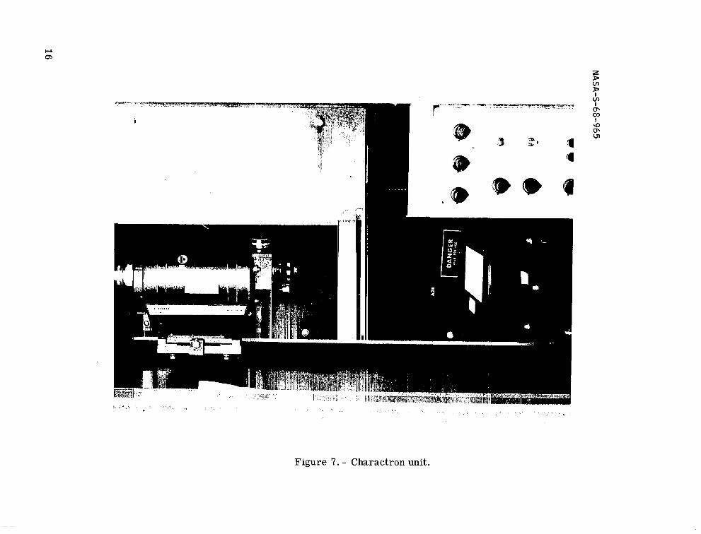
There are two types of input units: information units (fig. 6) and control units (figs. 6 and 7). duces printed and pictorial material into the system and the punched-paper-tape reader. Control units instruct the system and include the strobe-control keyboard, the
The information units are the alphanumeric keyboard which intro-
2
1
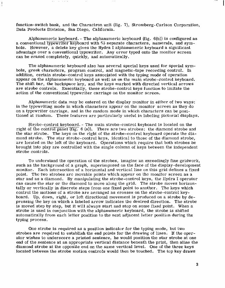
function-switch bank, and the Charactron unit (fig. 7), Stromberg-Carlson Corporation, Data Products Division, San Diego, California.
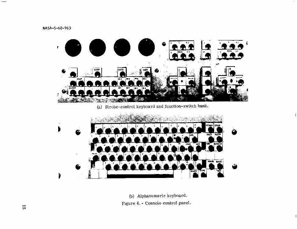
Alphanumeric keyboard. - The alphanumeric keyboard (fig. 6(b)) is configured as a conventional typewriter keyboard with 55 separate characters , numerals, and sym- bols. However, a delete key gives the Hydra I alphanumeric keyboard a significant advantage over a conventional typewriter. Any e r r o r typed onto the monitor sc reen can be erased completely, quickly, and automatically.
The alphanumeric keyboard also has several special keys used for special sym- bols, greek characters , program control, and magnetic-tape recording control. In addition, certain strobe-control keys associated with the typing mode of operation appear on the alphanumeric keyboard as well as on the main strobe-control keyboard. The shift bar, the backspace key, and the keys marked with directed vertical a r rows are strobe controls. action of the conventional typewriter carr iage on the monitor screen,
Essentially, these strobe-control keys function to imitate the
Alphanumeric data may be entered on the display monitor in either of two ways: in the typewriting mode in which characters appear on the monitor screen as they do on a typewriter carr iage, and in the random mode in which characters can be posi- tioned at random. These features are parti,cularly useful in labeling pictorial displays.
Strobe-control keyboard. - The main strobe-control keyboard is located on the right of the control p a n e l m - 6 (a)). There arestwo s t robes: the diamond s t robe and the star strobe. The keys on the right of the strobe-control keyboard operate the dia- mond strobe. The star strobe-control keys, identical t o those of the diamond strobe, are located on the left of the keyboard. Operations which require that both s t robes be brought into play are controlled with the single column of keys between the independent s t robe controls.
To understand the operation of the s t robes, imagine an exceedingly fine gridwork, such as the background of a graph, superimposed on the face of the display-development monitor. Each intersection of a horizontal and vertical line on this grid defines a fixed point. The two s t robes a r e movable points which appear on the monitor screen as a star and as a diamond. By manipulating the strobe-control keys, the Hydra I operator can cause the star o r the diamond to move along the grid. The s t robe moves horizon- tally o r vertically in discrete s teps from one fixed point to another. The keys which control the motions of a s t robe are arranged as crosses on the strobe-control key- board. Up, down, right, o r left directional movement is produced on a strobe by de- pressing the key on which a labeled arrow indicates the desired direction. The s t robe is moved s tep by step, but it will always start and stop on some fixed point. When a strobe is used in conjunction with the alphanumeric keyboard, the strobe is shifted automatically from each letter position t o the next adjacent letter position during the typing process.
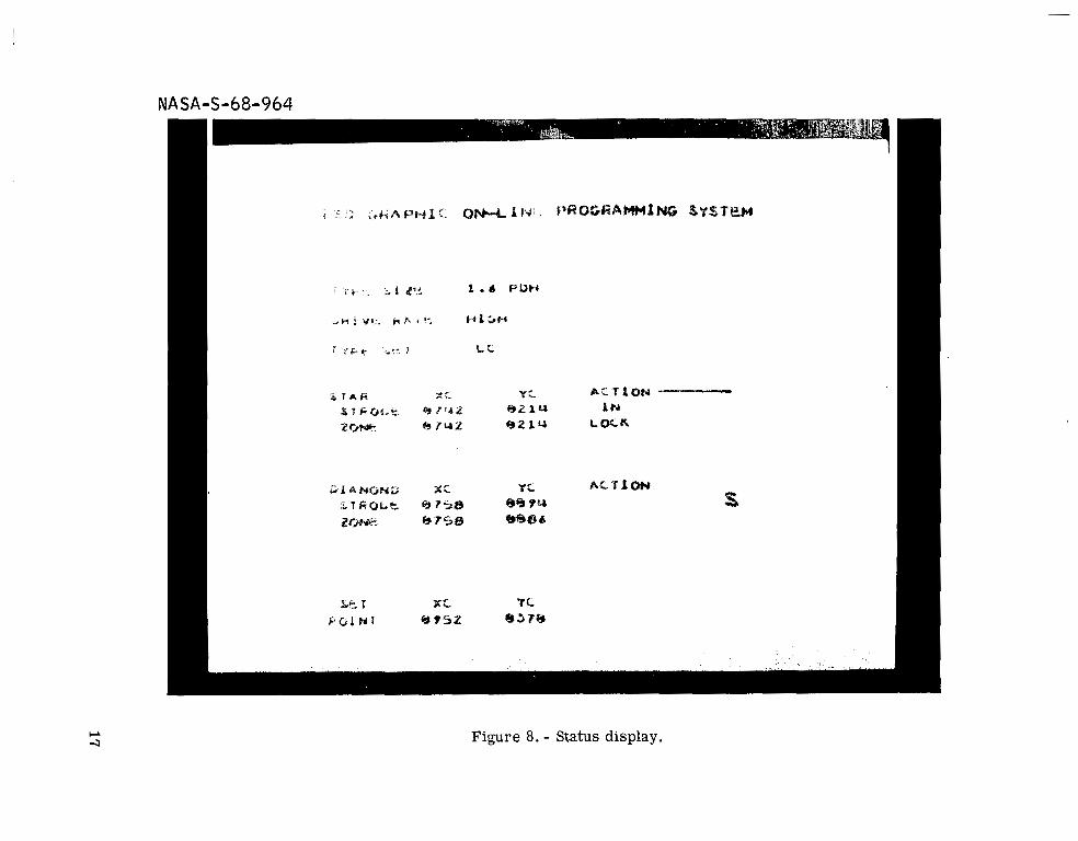
One s t robe is required as a position indicator fo r the typing mode, but two s t robes are required to establish the end points for the drawing of lines. If the oper- a tor wishes to underscore a printed sentence, he would position the star strobe at one end of the sentence at an appropriate vertical distance beneath the print, then aline the diamond strobe at the opposite end on the same vertical level. One of the three keys located between the s t robe motion controls would then be touched. The top key draws
3
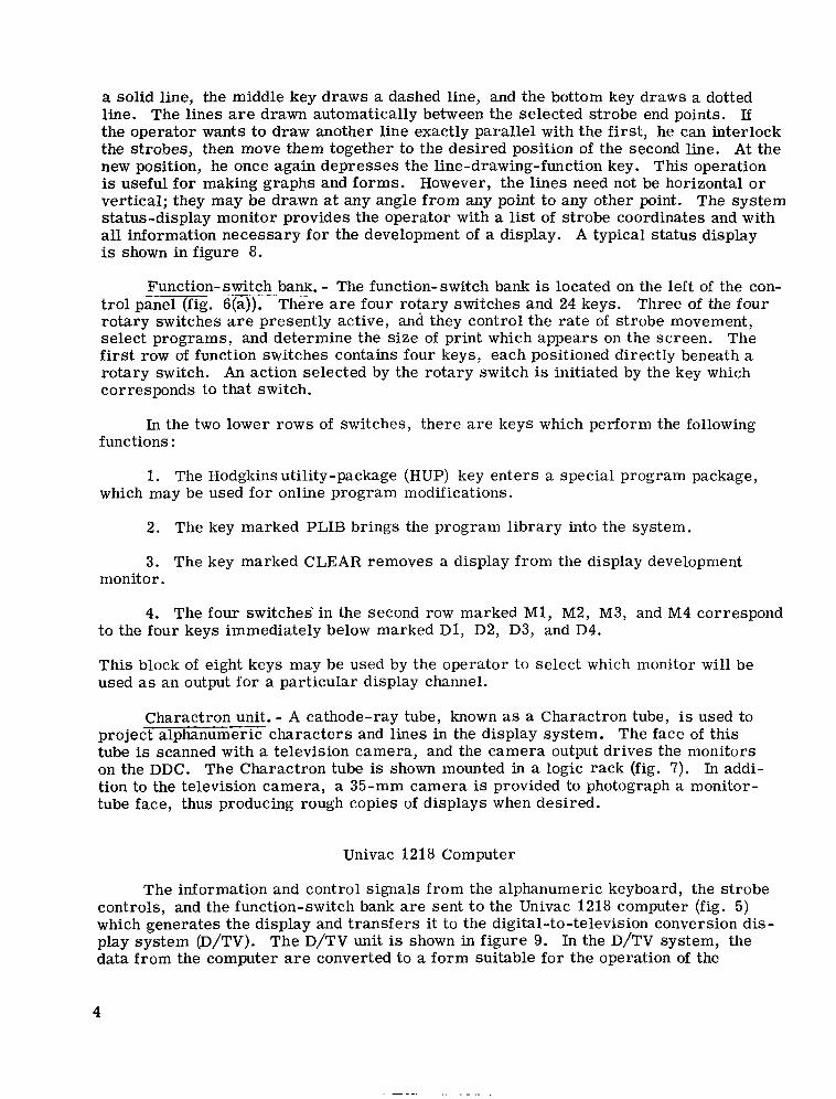
a solid line, the middle key draws a dashed line, and the bottom key draws a dotted line. The l ines are drawn automatically between the selected strobe end points. If the operator wants to draw another line exactly parallel with the first, he can interlock the strobes, then move them together to the desired position of the second line. At the new position, he once again depresses the line-drawing-function key. This operation is useful for making graphs and forms. However, the l ines need not be horizontal o r vertical; they may be drawn at any angle f rom any point to any other point. The system status-display monitor provides the operator with a list of strobe coordinates and with all information necessary for the development of a display. A typical status display is shown in figure 8.
Function-switch ~ ___-____ bank. = - The function-switch bank is located on the left of the con- t ro l panel (fig. 6(a)). There are four rotary switches and 24 keys. rotary switches are presently active, and they control the rate of strobe movement, select programs, and determine the s ize of print which appears on the screen. The first row of function switches contains four keys, each positioned directly beneath a rotary switch. An action selected by the rotary switch is initiated by the key which corresponds to that switch.
Three of the four
In the two lower rows of switches, there are keys which perform the following functions :
1. The Hodgkins utility-package (HUP) key enters a special program package, which may be used for online program modifications.
2. The key marked PLIB brings the program l ibrary into the system.
3. The key marked CLEAR removes a display from the display development monitor.
4. The four switches in the second row marked M1, M2, M3, and M4 correspond to the four keys immediately below marked D1, D2, D3, and D4.
This block of eight keys may be used by the operator to select which monitor will be used as an output for a particular display channel.
Charactron unit. - A cathode-ray tube, known as a Charactron tube, is used to p r o j e c t c h a r a c t e r s and l ines in the display system. The face of this tube is scanned with a television camera, and the camera output drives the monitors on the DDC. The Charactron tube is shown mounted in a logic rack (fig. 7). In addi- tion to the television camera, a 35-mm camera is provided to photograph a monitor- tube face, thus producing rough copies of displays when desired.
Univac 1218 Computer
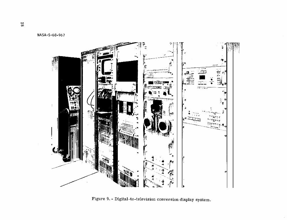
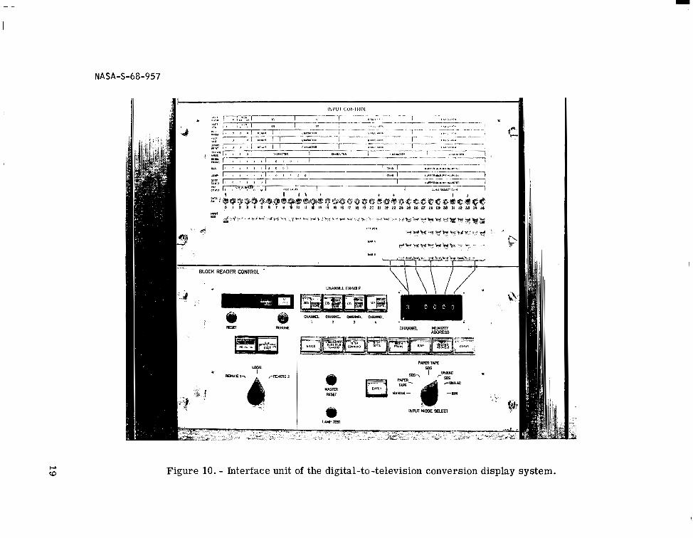
The information and control signals from the alphanumeric keyboard, the s t robe controls, and the function-switch bank are sent t o the Univac 1218 computer (fig. 5) which generates the display and t ransfers it to the digital-to-television conversion dis- play system (D/TV). The D/TV unit is shown in figure 9. In the D/TV system, the data f rom the computer are converted to a form suitable for the operation of the
4
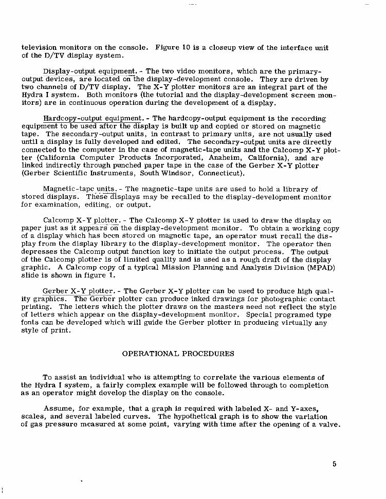
television monitors on the console. Figure 10 is a closeup view of the interface unit of the D/TV display system.
Display-output equipment. - The two video monitors, which are the primary- output devices, are located on the display-development console. They are driven by two channels of D/TV display. The X-Y plotter monitors are an integral par t of the Hydra I system. i tors) are in continuous operation during the development of a display.
Both monitors (the tutorial and the display-development sc reen mon-
Hardcopy-output equipment. - The hardcopy-output equipment is the recording equipment to be used after the display is built up and copied o r stored on magnetic tape. The secondary-output units, in contrast to pr imary units, are not usually used until a display is fully developed and edited, The secondary-output units are directly connected t o the computer in the case of magnetic-tape units and the Calcomp X-Y plot- ter (California Computer Products Incorporated, Anaheim, California), and are linked indirectly through punched paper tape in the case of the Gerber X-Y plotter (Gerber Scientific Instruments, South Windsor, Connecticut).
Magnetic-tape units. - The magnetic-tape units are used to hold a l ibrary of stored-displays. for examination, editing, o r output.
These displays may be recalled to the display-development monitor
Calcomp X-Y plotter. - The Calcomp X-Y plotter is used to draw the display on paper just as it appears on the display-development monitor. To obtain a working copy of a display which has been s tored on magnetic tape, an operator must recal l the dis- play from the display l ibrary t o the display-development monitor. The operator then depresses the Calcomp output function key to initiate the output process . The output of the Calcomp plotter is of limited quality and is used as a rough draft of the display graphic. A Calcomp copy of a typical Mission Planning and Analysis Division (MPAD) slide is shown in figure 1.
Gerber X-Y plotter. - The Gerber X-Y plotter can be used to produce high qual- ity graphics. The Gerber plotter can produce inked drawings for photographic contact printing. The letters which the plotter draws on the mas ters need not reflect the style of letters which appear on the display-development monitor. fonts can be developed which will guide the Gerber plotter in producing virtually any style of print.
Special programed type
OPERATIONAL PROCEDURES
To assist an individual who is attempting to correlate the various elements of the Hydra I system, a fair ly complex example will be followed through to completion as an operator might develop the display on the console.
Assume, for example, that a graph is required with labeled X- and Y-axes, scales, and several labeled curves. The hypothetical graph is to show the variation of gas pressure measured at some point, varying with t ime after the opening of a valve.
5
Other valves are then substituted into the system with each valve generating a separate pressure versus t ime curve. The Hydra I operator would need only a list of the empir- ical resul ts of such an experiment to construct the graph.
The first production requirement, in this case, is the background grid of the graph which can be readily drawn using the s t robe controls. The two s t robes (indicated by a star and a diamond) are locked into relative position. With the s t robes locked, the touching of the direction key indicating UP, for instance, would result in both the star and diamond moving up. A line drawn between the two strobes, accomplished by touching the proper line key, can then be generated at any position on the screen. In drawing the parallel lines which make up the background grid of the graph, the oper- a tor might follow this sequence of control:
1. The star and the diamond would be alined on the same vertical level on the screen at a measured distance apart .
2. The alinement is checked against the list of strobe coordinates on the status display monitor.
3. When in the desired relation, the top line-drawing key on the strobe control keyboard would be touched making the lowest line of the graph appear on the screen.
4. The s t robes would be locked and, using one or the other of the direction keys, both s t robes would be moved up a measured number of vertical increments.
5. Another line would be drawn at this point which would exactly and automat- ically parallel the first line.
6. This method would be very rapid, with pauses only to move the s t robes the required number of vertical increments after the drawing of each line, until all of the horizontal l ines of the gridwork are completed.
7. The s t robes would then be unlocked, alined again in a vertical plane, and locked once again to complete the vertical lines of the gridwork.
8. Graph lines are drawn in over the completed gridwork by using the two s t robes as alternate data points.
9. Labels and legends on the display can be accomplished by using the facilities of the alphanumeric keyboard to complete the production.
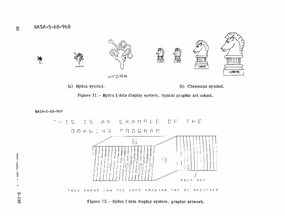
Figures l l (a) and l l ( b ) show examples of various s teps in graphic development produced on the Hydra I. The hydra and chessman symbols were produced by single keys on the alphanumeric keyboard, as though they were alphanumeric characters.
The procedure described is an outline of one method of producing a graphic dis- play on the monitor screen of the Hydra I using the fully automatic parameters to ac - complish the desired results. There is no limit to the number of types of graphic displays which could be produced by an adept operator using this method alone. The functions of all the numerous input controls and components incorporated into the pres - ent Hydra I system were analyzed in an attempt to define limitations of the unit as a
6
. .. . . . . . . . . ._ -
whole. Operational specialists and experimental efforts have already disclosed that practically any reproducible mater ia l o r data can be composed, edited, rearranged, and t ransferred to or duplicated on the monitor sc reen of the Hydra I.
POTENTIAL APPLICATIONS
Several areas are suggested in which the Hydra I system could be particularly useful. This is not meant t o imply that the system is fully implemented in any of the areas, but rather to suggest directions which u s e r s might follow in accordance with requirements. Once the requirements are established, the Hydra I development group can adapt the system to particular needs.
Management Support
The Hydra I can be very useful in providing management support. Any manage- ment operation which requires compilation, storage, and frequent updating of forms (such as accounting processes o r supply record keeping) can be streamlined with the Hydra I. Accounts could be set up on the system, stored in mass memory, and re- called for updating, review, o r printout. Historical records may be kept readily avail- able for each form filed, displaying the updated changes in the sequence in which they were made. The files could be searched for particular data-summary totals, and re- ports could be composed automatically and copied using either a line pr inter o r an X-Y plotter.
Another system application which might be of interest to management is the pro-
Complete standard-size char ts can be produced using a wide pen o r a felt pen- duction of briefing charts. These charts may be compiled, stored, and updated quite easily. cil installed in the Gerber X-Y plotter. If a slide presentation is desired, the plotter can scr ibe viewgraph o r overhead projector sl ides suitable for projection.
Graphic Artwork
General graphic artwork is the for te of Hydra I. The system can be used to set up block diagrams, charts, and overlays annotated with alphanumeric material. Fre- quently used graphic formats and drafting forms can be stored and displayed. The sys- tem is particularly useful for graphics which must be updated frequently. A typical example of graphic artwork produced is shown in figure 12.
Hydra I graphic artwork has been extended into areas of engineering design. Standard logic o r electronic symbols, such as the standard integrated-circuit logic symbols, can be programed into the system, and the operator can then create logic o r circuit diagrams online.
7
Mission Planning, Review, and Analysis
The Hydra I system is capable of producing displays based on computer-generated data f o r trajectory and orbital parameters . These displays can be included in mission planning do cumentat ion.
Mission log tapes may be displayed sequentially fo r postmission review. The activities of the flight controller may be analyzed, and monitoring data may be com- piled for study. The system is capable of producing animated displays. An application of this capability is the production of animated ba r graphs, each bar representing some parameter which var ies with t ime.
Development of Illustrations for Documents
Hydra I, because of the memory capacity and the typesetting capability, is ideally suited for the development of illustrations for documents using the special control con- soles, and mission documentation personnel can develop illustrations and s tore the pages in individual data files in the display l ibrary. A page may be recalled from s tor - age at any t ime to be updated. The system operator is able to delete o r add material at random within an illustration with no laborious retyping of material necessary to accommodate the changes.
The system does well in producing printed documentation, but there is one re- striction. Although it is relatively simple to delete material from text and to inser t new material in its place, the revision must be made in section blocks of uniform size. As yet, there is no means of opening the stack of print to inser t additional text o r clos- ing the stack to take up the space left by deleted text.
CONCLUDING REMARKS
There is no limit to the number of types of graphic displays that an adept oper- a tor can produce with the Hydra I data display system. The Hydra I system is capable of reproducing written documents, char ts , diagrams, background slides, and other graphic arts. The Hydra I has applications in management support; graphic artwork; and mission planning, review, and analysis. Because of the memory capacity and the typesetting capability, the Hydra I system is suited to the development of illustrations f o r documents. plotted on an X-Y plotter, recorded on punched paper tape, or recorded as a f rame of a sequential-playback magnetic tape. The disadvantage of the Hydra I system is that the revisions must be made in section blocks of uniform size.
The graphic displays can be recorded in a magnetic-tape l ibrary,
Manned Spacecraft Center National Aeronautics and Space Administration
Houston, Texas, February 9, 1968 921-40-01-00-72
8
NASA-S-68-958
Figure 1. - Data development console.
NASA-S-68-959
. .
Figure 2. - Look and change program, before change.
NASA-S-68-960
A
Figure 3. - Look and change program, after change.
I_-- C ' Q L C C E P X . Y P L O T T E R
(a) Block diagram.
Figure 4. - Hydra I data display system.
NASA-S-68-962
O P E R A T I N G
C O N T R O L S >
D I G I T A L G R A P H I C S U B S Y S T E / ” l
S W I T C H I N G Q N O
C O N T R O L L O G I C
I N C R E P E N T A L
> P A G N E T I C
T A P E U N I T
F ) U X I L I A R Y G R F I P Y I C I N P U T E Q U I P P E N T G R O U P
v
(b) Digital graphic subsystem.
Figure 4. - Concluded.
NASA-S-68-966
. .. ..__. .-
Figure 5. - Univac 1218 computer.
14
NASA-S-68-963
(a) Strobe-control keyboard and function-switch bank.
1)
(b) Alphanumeric keyboard.
Figure 6. - Console control panel.
I
z D v, D
Figure 7. - Charactron unit.
NA SA-S-68-964
Figure 8. - Status display.
NASA-S-68-967
t I ’ 9 b I
Figure 9. - Digital-to-television conversion display system.
NASA
Figure 10. - Interface unit of the digital-to-television conversion display system.
L\3 NASA-S-68-968 0
m I
CL w QJ
V
H Y D R A
(a) Hydra symbol. (b) Chessman symbol.
Figure 11. - Hydra I data display system, typical graphic art output.
NASA-S-68-969
W I . S I S A N E X A M P L E O F HE
D R P W I N G P S C G R A M
T Y I S S Y 3 U S ~ O c l T H C S P P C O R A U I N G W Q " J C f l @ L ! J F I C @
Figure 12. - Hydra I data display system, graphic artwork.
NATIONAL AERONAUTICS AND SPACE ADMINISTRATION WASHINGTON, D. C. 20546
-- OFFICIAL BUSINESS FIRST CLASS MAIL
POSTAGE AND FEES PAID NATIONAL AERONAUTICS ANE
SPACE ADMINISTRATION
,'t ,- i t - ( - i F i . I ' S
POSTMASTER: If Undeliverable (Section 158 Postal Manual) Do Not Returi
"The aerona~tical and sface activities of the United States shall be condzicted so as to contribute , . . t o the expansion of human Knowl- edge of phenomena in the atmosphere and space. T h e Administration shall pov ide for the widest practicable and appropriate dissenzindtion of information concerning its activities aizd the ~eszilts thereof."
-NATIONAL AERONAUTICS AND SPACE ACT OF 1958
NASA SCIENTIFIC AND TECHNICAL PUBLICATIONS
TECHNICAL REPORTS: Scientific and technical information considered important, complete, and a lasting contribution to existing knowledge.
TECHNICAL NOTES: Information less broad in scope but nevertheless of importance as a contribution to existing knowledge.
TECHNICAL MEMORANDUMS : Information receiving limited distribution because of preliminary data, security classifica- tion, or other reasons.
CONTRACTOR REPORTS: Scientific and technical information generated under a NASA contract or grant and considered an important contribution to existing knowledge.
TECHNICAL TRANSLATIONS: Information published in a foreign language considered to merit NASA distribution in English.
SPECIAL PUBLICATIONS: Information derived from or of value to NASA activities. Publications include conference proceedings, monographs, data compilations, handbooks, sourcebooks, and special bibliographies.
TECHNOLOGY UTILIZATION PUBLICATIONS: Information on technology used by NASA that may be of particular interest in commercial and other non-aerospace npplicationc. Publications include Tech Briefs, Technology Utilization Reports and Notes, and Technology Surveys.
Details on the availability of these publications may be obtained from:
SCIENTIFIC AND TECHNICAL INFORMATION DIVISION
NATI 0 NA L AER 0 N AUT1 CS AN D SPACE AD M I N I STRATI 0 N Washington, D.C. 20546