hydraulic pallet truck owner’s manual - … · hydraulic pallet truck owner’s manual hydraulic...
TRANSCRIPT
Thank you very much for choosing a NORTHERN TOOL + EQUIPMENT CO., INC. Product! For future reference, please complete the owner’s record below: Model: _______________ Purchase Date: _______________Save the receipt, warranty and these instructions. It is important that you read the entire manual to become familiar with this product before you begin using it.
This machine is designed for certain applications only. Northern Tool + Equipment cannot be responsible for issues arising from modification. We strongly recommend this machine is not modified and/or used for any application other than that for which it was designed. If you have any questions relative to a particular application, DO NOT use the machine until you have first contacted Northern Tool + Equipment to determine if it can or should be performed on the product.
For technical questions please call 1-800-222-5381.
WARNING1. Do not operate a Hand Pallet Truck unless you are familiar with it and have been trained and
authorized to do so. Read all warnings and instructions here and on the truck.2. Do not operate a Hand Pallet Truck until you have checked its condition. Give special attention to
the wheels, handle, forks, raising and lowering control, and brakes (if so equipped). Do not operate a damaged or faulty truck. Do not attempt repairs unless you are trained and authorized to do so.
3. Operate Hand Pallet Truck only from the designated operating position. Never place any part of your body in the lifting mechanism or under the forks or load. Do not carry passengers.
4. Do not handle unstable or loosely stacked loads. Use special care when handling long, high or wide loads to avoid losing the load, striking bystanders, or tipping the truck.
5. Do not overload the truck. Check capacity plate for load capacity information. Overloading may cause truck to perform incorrectly and unsafely.
6. The capacity of tile truck assumes an evenly distributed load, with the center of the load being the halfway point of the tile fork length.
7. Make sure that length of tile forks match the length of the pallet. Using a pallet truck where the forks are longer than the pallet will damage the truck if the pallet truck is pushed through the pallet and the forks are under a second pallet behind the one being lifted. When lowering the load, make sure the area where the pallet is to be placed is clear.
8. Observe traffic regulations. Yield right of way to pedestrians. Stop at cross aisles.9. Hand Pallet Trucks are for general operation on level, flat hard surfaces. If ramps are
encountered, the hand brake can be employed, or the truck may be stopped in emergencies by operating the lowering control, which will lower load to the ground, stopping the truck. If the truck has to be stopped in this manner, care should be taken so that no part of your body is near or under the load. It is important not to operate a Hand Pallet Truck on a grade with loads that are too heavy to be easily handled by the operator since they are manually operated trucks. They are not to be used by operators that are not physically capable of safely handling a truck with a load.
FAILURE TO FOLLOW THESE INSTRUCTIONS MAY CAUSE SERIOUS INJURY TO THE OPERATOR OR OTHERS.
Jack and Fork Frame Assembly1. Refer to illustration(1) According the sequence as follows:2. Turn fork frame over.
HYDRAULIC PALLET TRUCK OWNER’S MANUAL
HYDRAULIC PALLET TRUCK OWNER’S MANUAL HYDRAULIC PALLET TRUCK OWNER’S MANUAL HYDRAULIC PALLET TRUCK OWNER’S MANUAL
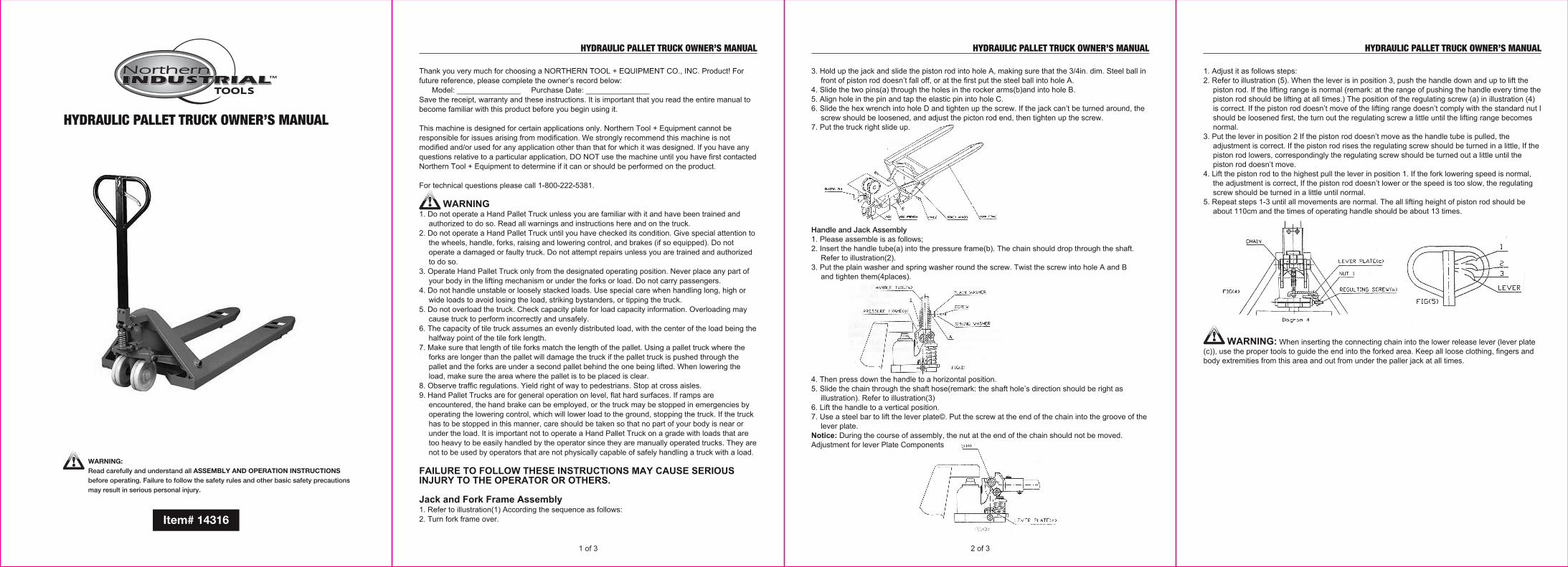
WARNING:Read carefully and understand all ASSEMBLY AND OPERATION INSTRUCTIONSbefore operating. Failure to follow the safety rules and other basic safety precautionsmay result in serious personal injury.
3. Hold up the jack and slide the piston rod into hole A, making sure that the 3/4in. dim. Steel ball in front of piston rod doesn’t fall off, or at the first put the steel ball into hole A.
4. Slide the two pins(a) through the holes in the rocker arms(b)and into hole B.5. Align hole in the pin and tap the elastic pin into hole C.6. Slide the hex wrench into hole D and tighten up the screw. If the jack can’t be turned around, the
screw should be loosened, and adjust the picton rod end, then tighten up the screw. 7. Put the truck right slide up.
Handle and Jack Assembly1. Please assemble is as follows;2. Insert the handle tube(a) into the pressure frame(b). The chain should drop through the shaft.
Refer to illustration(2).3. Put the plain washer and spring washer round the screw. Twist the screw into hole A and B
and tighten them(4places).
4. Then press down the handle to a horizontal position.5. Slide the chain through the shaft hose(remark: the shaft hole’s direction should be right as
illustration). Refer to illustration(3)6. Lift the handle to a vertical position.7. Use a steel bar to lift the lever plate©. Put the screw at the end of the chain into the groove of the
lever plate.Notice: During the course of assembly, the nut at the end of the chain should not be moved.Adjustment for lever Plate Components
1 of 3 2 of 3
1. Adjust it as follows steps:2. Refer to illustration (5). When the lever is in position 3, push the handle down and up to lift the
piston rod. If the lifting range is normal (remark: at the range of pushing the handle every time the piston rod should be lifting at all times.) The position of the regulating screw (a) in illustration (4) is correct. If the piston rod doesn’t move of the lifting range doesn’t comply with the standard nut I should be loosened first, the turn out the regulating screw a little until the lifting range becomes normal.
3. Put the lever in position 2 If the piston rod doesn’t move as the handle tube is pulled, the adjustment is correct. If the piston rod rises the regulating screw should be turned in a little, If the piston rod lowers, correspondingly the regulating screw should be turned out a little until the piston rod doesn’t move.
4. Lift the piston rod to the highest pull the lever in position 1. If the fork lowering speed is normal, the adjustment is correct, If the piston rod doesn’t lower or the speed is too slow, the regulating screw should be turned in a little until normal.
5. Repeat steps 1-3 until all movements are normal. The all lifting height of piston rod should be about 110cm and the times of operating handle should be about 13 times.
WARNING: When inserting the connecting chain into the lower release lever (lever plate (c)), use the proper tools to guide the end into the forked area. Keep all loose clothing, fingers and body extremities from this area and out from under the paller jack at all times.
Item# 14316
HYDRAULIC PALLET TRUCK OWNER’S MANUAL HYDRAULIC PALLET TRUCK OWNER’S MANUAL
2 of 3
3 of 3
Distributed byNorthern Tool & Equipment Co., Inc.
Burnsville, MN 55306-6936NorthernTool.com
Made in China.
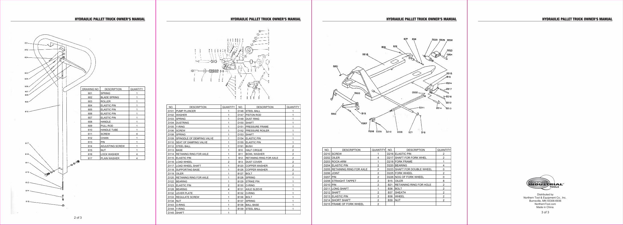
DRAWING NO DESCRIPTION QUANTITY601 SPRING 1602 BLADE SPRING 1603 ROLLER 1604 ELASTIC PIN 1605 ELASTIC PIN 1606 ELASTIC PIN 1607 ELASTIC PIN 1608 HANDLE 1609 PULL ROD 1610 HANDLE TUBE 1611 SCREW 4612 CHAIN 1613 PIN 1614 ADJUSTING SCREW 1615 NUT 1616 LOCK WASHER 4617 PLAIN WASHER 4
NO. DESCRIPTION QUANTITY NO. DESCRIPTION QUANTITYD101 PUMP PLUNCER 1 D146 STEEL BALL 1D102 WASHER 1 D147 PISTON ROD 1D103 SPRING 1 D148 DUST RING 1D104 DUSTRING 1 D150 SHAFT 1D105 Y-RING 1 D151 PRESSURE FRAME 1D106 SCREW 1 D152 PRESSURE ROILER 1D108 SPRING 1 D153 SHAFT 1D109 SPINGDLE OF DEMPING VALVE 1 D154 ELASTIC PIN 1D110 SEAT OF DAMPING VALVE 1 D155 ELASTIC PIN 1D112 STEEL BALL 1 D191 BUSH 2D113 BASE 1 B10 HALF CIRQUE 2D114 RETANING RING FOR AXLE 1 B11 BOWL WASHER 2D115 ELASTIC PIN 1 B12 RETANING RING FOR AXLE 2D116 LOAD WHEEL 2 B13 DUST COVER 2D117 LOAD WHEEL SHAFT 1 B120 COPPER WASHER 2D118 SUPPORTING BASE 1 B126 COPPER WASHER 2D119 OILER 1 B127 BOLT 2D120 RETANING RING FOR AXLE 1 B128 SPRING 1D122 BEARING 1 B129 STRIKE PIN 1D123 ELASTIC PIN 2 B130 O-RING 1D128 BEARING 4 B131 AXLE SLEEVE 1D132 LEVER PLATE 1 B132 O-RING 1D133 REGULATE SCREW 1 B136 BOLT 1D134 NUT 1 B137 SPRING 1D143 O-RING 1 B138 BALL BASE 1D144 Y-RING 1 B139 STEEL BALL 1D145 SHAFT 1
HYDRAULIC PALLET TRUCK OWNER’S MANUAL
NO. DESCRIPTION QUANTITY NO. DESCRIPTION QUANTITYD210 SCREW 1 D216 ELASTIC PIN 2D202 OILER 4 D217 SHAFT FOR FORK WHEL 2D203 ROCK-ARM 1 D218 FORK FRAME 1D204 ELASTIC PIN 2 D220 BEARING 4D205 RETAINING RING FOR AXLE 2 D223 SHAFT FOR DOUBLE WHEEL 0D206 JOINT 2 D225 FORK WHEEL 2D207 PIN 2 D226 NOG OF FORK WHEEL 0D208 STRAIGHT TAPPET 2 B15 OILER 8D210 PIN 2 B21 RETAINING RING FOR HOLE 2D211 LONG SHAFT 1 B36 BOLT 2D212 SHAFT 2 B37 SHEATH 2D213 ELASTIC PIN 2 B38 WHEEL 2D214 SHORT SHAFT 2 B39 NUT 2D215 FRAME OF FORK WHEEL 2
HYDRAULIC PALLET TRUCK OWNER’S MANUAL