hydrocarbon fire protection of structural steelwork … · fmfm fm fm method statement fm ms 08 fb...
TRANSCRIPT
FMFM FM
FM
Method Statement FM MS 08 FB Hydrocarbon fire protection of structural
steelwork using FireMaster FB 100
Rev 0: October 2016
FM MS 08 FB Rev 0
www.morganadvancedmaterials.com
Morgan Thermal Ceramics, Tebay Rd., Bromborough, CH62 3PH. England
FM MS 08 FB Rev 0 October 2016
.
CONTENTS
1 Introduction and Overview of system concept 1.1. System Description
1.2. FireMaster FB 100 Product Specification
1.3. Fire testing and Certification
2 Installation Procedure 2.1. Preparation of steel surface
2.2. Fixing of retention mesh
2.3. Spray Equipment Required
2.4. Setting the correct mix of FireMaster FB 100 and water
2.5. Spray Application Technique
2.6. Quality Assurance during installation
3 Post-Installation Procedures 3.1. Inspection and Repair

FM MS 08 FB Rev 0
www.morganadvancedmaterials.com
Morgan Thermal Ceramics, Tebay Rd., Bromborough, CH62 3PH. England
FM MS 08 FB Rev 0 October 2016
.
1 Introduction and Overview of System Concept
1.1 System Description
The system consists of sprayed application of FireMaster FB 100, a lightweight cementitious fire protection
material, onto a supporting mesh attached to the steelwork. The mesh is retained on the steelwork using
metal anchor studs. The system is UL approved for up to 4 hours hydrocarbon fire protection of structural
steelwork.
The basic steps of installation are:
1. Fix steel mesh to the steelwork 2. Spray FireMaster FB100 into place over mesh 3. Level surface of FireMaster FB 100 if a smooth surface is required 4. Allow to dry for approximately 2-3 hours 5. Allow to dry for 24 to 48 hours before applying any surface coating (if required) depending on climate

FM MS 08 FB Rev 0
www.morganadvancedmaterials.com
Morgan Thermal Ceramics, Tebay Rd., Bromborough, CH62 3PH. England
FM MS 08 FB Rev 0 October 2016
.
FireMaster FB 100 Product Specification
See Product Data Sheet on the following pages for product description and technical data.

THERMAL CERAMICS
Data sheet
FB100 Fire protection for structural steelwork and concrete tunnels
ENGLISH
DescriptionFireMaster® FB100 is a cementitious material designed for a variety of industrial and infrastructure fire protection applications requiringstrong and weather resistant exterior finishes.
FB100 is spray applied in one or more passes up to 50mm thickness, and canbe troweled to a smooth aesthetic finish.
Fire protection properties� Class A1 Reaction to fire in accordance with EN 13501-1 : 2009� UL Listing XR735 for 1 to 4 hour protection per UL1709 on structural steel. UL Listing XR735
� Tested for up to 3 hour fire protection against RWS exposure at SP in Sweden
Environmental Exposure Testing per UL1709� Accelerated aging, exposure to 80°C for 135 days� High humidity, exposure to 95% RH for 180 days� Industrial atmosphere, exposure to SO2 and CO2 for 30 days� Salt Spray, exposure per ASTM B117 for 90 days� Combination wet, freeze, thaw, exposure to 12 cycles� Acid Spray, exposure to spray fog of 2% by volume hydrochloric acid (HCI) for 5 days
www.morganthermalceramics.com© 2016 Thermal Ceramics, a business of Morgan Advanced Materials 02/2016 Page 1 of 2

Contact
Europe:Telephone:+44 (0) 151 334 4030
E-mail:
North America:Telephone:+1 (706) 796 4200
E-mail:
South America:Telephone:+54 (11) 4373 4439
E-mail:
Asia:Telephone:+65 6595 0000
E-mail:
Whilst the values and application informationin this datasheet are typical, they are givenfor guidance only. The values and the information given are subject to normalmanufacturing variation and may be subjectto change without notice. Morgan AdvancedMaterials – Thermal Ceramics makes noguarantees and gives no warranties aboutthe suitability of a product and you shouldseek advice to confirm the product’s suitability for use with Morgan AdvancedMaterials - Thermal Ceramics.
SUPERWOOL® is a patented technologyfor high temperature insulation wools which have been developed to have a lowbio persistence (information upon request).SUPERWOOL® products may be coveredby one or more of the following patents, ortheir foreign equivalents:
SUPERWOOL® PLUS and SUPERWOOL® HT products are coveredby patent numbers: US5714421 and US7470641, US7651965,US7875566, EP1544177 and EP1725503 respectively.
A list of foreign patent numbers is available upon request to Morgan AdvancedMaterials plc.
Morgan Advanced Materials plc Registeredin England & Wales at Quadrant, 55-57 High Street, Windsor, Berkshire SL4 1LP UK Company No. 286773
Data sheet
FB100 Fire protection for structural steelwork and concrete tunnels
www.morganthermalceramics.com© 2016 Thermal Ceramics, a business of Morgan Advanced Materials 02/2016 Page 2 of 2
THERMAL CERAMICS
Weight of dry material/m3 of construction Kg 800
Installed density Kg/m3 1170
FB100
Chemical composition %
SiO2 24.8Al2O3 18.0CaO 48.0Fe2O3 2.5TiO2 0.2
MgO+K2O+Na2O 5.8
Density after 48h Kg/m3 1060
Dry density 50°C Kg/m3 820
Cold crushing strength ASTM C-133 (50°C) MPa 1.8
Water to mix % 65
Adhesion strength ASTM E-736-00 (On steel surface) KPa 43
Hardeness ASTM D-2240 - Shore D @50°C 25
Availability and PackagingIn bags of 20kg weight supplied to site and ready to mix with water.
FM MS 08 FB Rev 0
www.morganadvancedmaterials.com
Morgan Thermal Ceramics, Tebay Rd., Bromborough, CH62 3PH. England
FM MS 08 FB Rev 0 October 2016
.
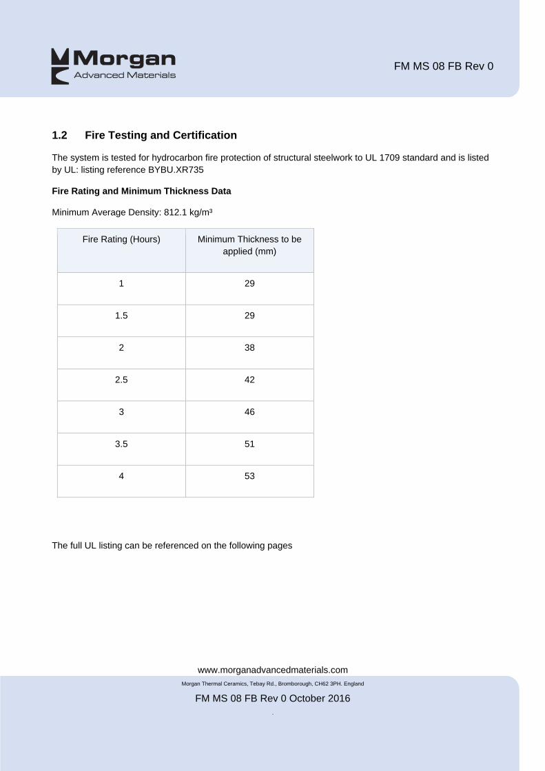
1.2 Fire Testing and Certification
The system is tested for hydrocarbon fire protection of structural steelwork to UL 1709 standard and is listed
by UL: listing reference BYBU.XR735
Fire Rating and Minimum Thickness Data
Minimum Average Density: 812.1 kg/m³
Fire Rating (Hours) Minimum Thickness to be
applied (mm)
1 29
1.5 29
2 38
2.5 42
3 46
3.5 51
4 53
The full UL listing can be referenced on the following pages
FM MS 08 FB Rev 0
www.morganadvancedmaterials.com
Morgan Thermal Ceramics, Tebay Rd., Bromborough, CH62 3PH. England
FM MS 08 FB Rev 0 October 2016
.
2. Installation Procedure
2.1 Preparation of Steel Surface
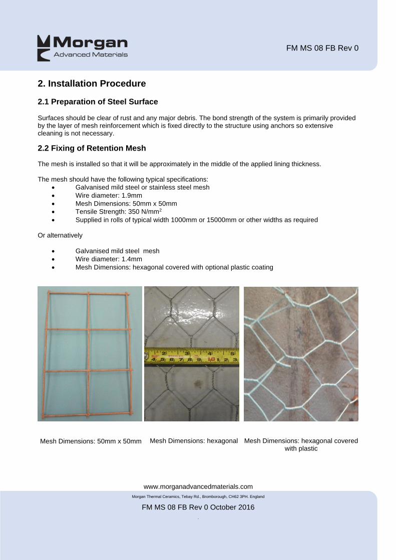
Surfaces should be clear of rust and any major debris. The bond strength of the system is primarily provided by the layer of mesh reinforcement which is fixed directly to the structure using anchors so extensive cleaning is not necessary. 2.2 Fixing of Retention Mesh The mesh is installed so that it will be approximately in the middle of the applied lining thickness. The mesh should have the following typical specifications:
Galvanised mild steel or stainless steel mesh
Wire diameter: 1.9mm
Mesh Dimensions: 50mm x 50mm
Tensile Strength: 350 N/mm2
Supplied in rolls of typical width 1000mm or 15000mm or other widths as required
Or alternatively
Galvanised mild steel mesh
Wire diameter: 1.4mm
Mesh Dimensions: hexagonal covered with optional plastic coating
Mesh Dimensions: 50mm x 50mm
Mesh Dimensions: hexagonal Mesh Dimensions: hexagonal covered with plastic

Design/System/Construction/Assembly Usage Disclaimer
� Authorities Having Jurisdiction should be consulted in all cases as to the particular requirements covering the installation and use of UL
Certified products, equipment, system, devices, and materials.
� Authorities Having Jurisdiction should be consulted before construction.
� Fire resistance assemblies and products are developed by the design submitter and have been investigated by UL for compliance with
applicable requirements. The published information cannot always address every construction nuance encountered in the field.
� When field issues arise, it is recommended the first contact for assistance be the technical service staff provided by the product
manufacturer noted for the design. Users of fire resistance assemblies are advised to consult the general Guide Information for each
product category and each group of assemblies. The Guide Information includes specifics concerning alternate materials and alternate
methods of construction.
� Only products which bear UL's Mark are considered Certified.
BYBU - Fire-resistance Ratings - ANSI/UL 1709
See General Information for Fire-resistance Ratings - ANSI/UL 1709
Design No. XR735
January 05, 2016
Ratings — 1, 1-1/2, 2, 2-1/2, 3, 3-1/2, and 4 Hr.
1. Steel Column — Minimum size W10×49 (minimum W/D of 0.84 or Hp/A of 159).
2. Powder-Actuated Fasteners — Fasteners secured directly to steel column (Item 1) for purpose of anchoring steel
Design No. XR735 BYBU.XR735
Fire-resistance Ratings - ANSI/UL 1709 Page Bottom
Page 1 of 2BYBU.XR735 - Fire-resistance Ratings - ANSI/UL 1709
11/01/2016http://database.ul.com/cgi-bin/XYV/template/LISEXT/1FRA...

mesh (Item 3) to steel column. Fastener length approximately 2/3 to 3/4 of the final fireproofing thickness to be applied
(Item 4). Fasteners spaced 3/4 in. (19 mm) away from flange tips and 16 in. (406 mm) OC along height of column.
Fasteners also applied at inside corners of flanges and webs, spaced 16 in. (406 mm) OC along height of column.
3. Reinforcing Steel Mesh — Mesh with 2 in. (51 mm) tall by 3-3/4 in. (95 mm) wide hexagonal openings, 18 ga AWG (1
mm) diameter steel wire with PVC coating wrapped around perimeter of column. Mesh tied to head of powder-actuated
fasteners with 16 ga AWG (1.3 mm) wire. After wrapped around the column, cut ends are tied into each other. Side joints
are butted and tied into each other with 16 ga AWG (1.3 mm) wire spaced 8-10 in (203-254 mm) OC.
4. Spray-Applied Fire-Resistive Materials* — See table below for required thicknesses. Prepared by mixing with water
according to instructions printed on each bag of mixture. Mixture can be spray or trowel applied in one or more coats to the
column surfaces which must be clean and free of dirt, loose scale and oil. Minimum average density of 50.7 lb/ft3 (812.1
kg/m3), with minimum individual value of 46.6 lb/ft3 (746.5 kg/m3). For method of density determination, see Design
Information Section, Sprayed Material. Surface of material may be finished with a trowel.
THERMAL CERAMICS INC — Type FireMaster FireBarrier 100 investigated for exterior use.
* Indicates such products shall bear the UL or cUL Certification Mark for jurisdictions employing the UL or cUL Certification
(such as Canada), respectively.
© 2016 UL LLC
The appearance of a company's name or product in this database does not in itself assure that products so identified have been manufactured
under UL's Follow-Up Service. Only those products bearing the UL Mark should be considered to be Certified and covered under UL's Follow-Up
Service. Always look for the Mark on the product.
UL permits the reproduction of the material contained in the Online Certification Directory subject to the following conditions: 1. The Guide
Information, Assemblies, Constructions, Designs, Systems, and/or Certifications (files) must be presented in their entirety and in a non-misleading
manner, without any manipulation of the data (or drawings). 2. The statement "Reprinted from the Online Certifications Directory with permission
from UL" must appear adjacent to the extracted material. In addition, the reprinted material must include a copyright notice in the following
format: "© 2016 UL LLC".
Rating Hr Min Thickness (mm)
1 29
1-1/2 29
2 38
2-1/2 42
3 46
3-1/2 51
4 53
Last Updated on 2016-01-05
Questions? Print this page Terms of Use Page Top
Page 2 of 2BYBU.XR735 - Fire-resistance Ratings - ANSI/UL 1709
11/01/2016http://database.ul.com/cgi-bin/XYV/template/LISEXT/1FRA...

FM MS 08 FB Rev 0
www.morganadvancedmaterials.com
Morgan Thermal Ceramics, Tebay Rd., Bromborough, CH62 3PH. England
FM MS 08 FB Rev 0 October 2016
.
The mesh is held in place using anchors that are attached to the steelwork by welding or, alternatively using Hilti nails.
Hilti nail fixing of mesh Welded anchor fixing of mesh
Hiti Nail Fixing Gun Fixing Nails
The welded pins should be capable of being bent once through an angle of 45° and back to their original
position or, in the case of helical pins, rotated through 90° and back to the original location, without failure of
the weld.

FM MS 08 FB Rev 0
www.morganadvancedmaterials.com
Morgan Thermal Ceramics, Tebay Rd., Bromborough, CH62 3PH. England
FM MS 08 FB Rev 0 October 2016
.
2.3 Spray Equipment FireMaster FB 100 is supplied to site as a dry powder in standard sized or extra-large bags (refer to the product data sheet for weight and packaging details). It is mixed with water in a spray machine and the wet mix is then pumped through tubing to a spray nozzle where it is mixed with compressed air at the exit of the nozzle and sprayed into place. Spray equipment known to work well as applicators are:
PFT G4/G5 PFT ZP 3L
PFT ZP 3L
PFT G4/G5
Other pumps may also be used if demonstrated to be acceptable by Morgan Advanced Materials after a trial installation. The pump must have a mixing chamber in order to allow the complete mixing of FB 100 with the correct quantity of water before the wet mix is pumped through the applicator tube.
2.4 Setting up the correct mixture of FB 100 and water
First, ensure the spray machine is set up to deliver the correct consistency of FB 100. Different spray machines may require different ratios of water to FB 100 powder. The correct settings are governed by the viscosity of the wet mix as measured using a “Vicat” floating needle penetrometer.
As a guide for setting up the spray machine, the average water to FireBarrier 100 powder ratio is 70% (by weight) max 75% and min 65%
FM MS 08 FB Rev 0
www.morganadvancedmaterials.com
Morgan Thermal Ceramics, Tebay Rd., Bromborough, CH62 3PH. England
FM MS 08 FB Rev 0 October 2016
.
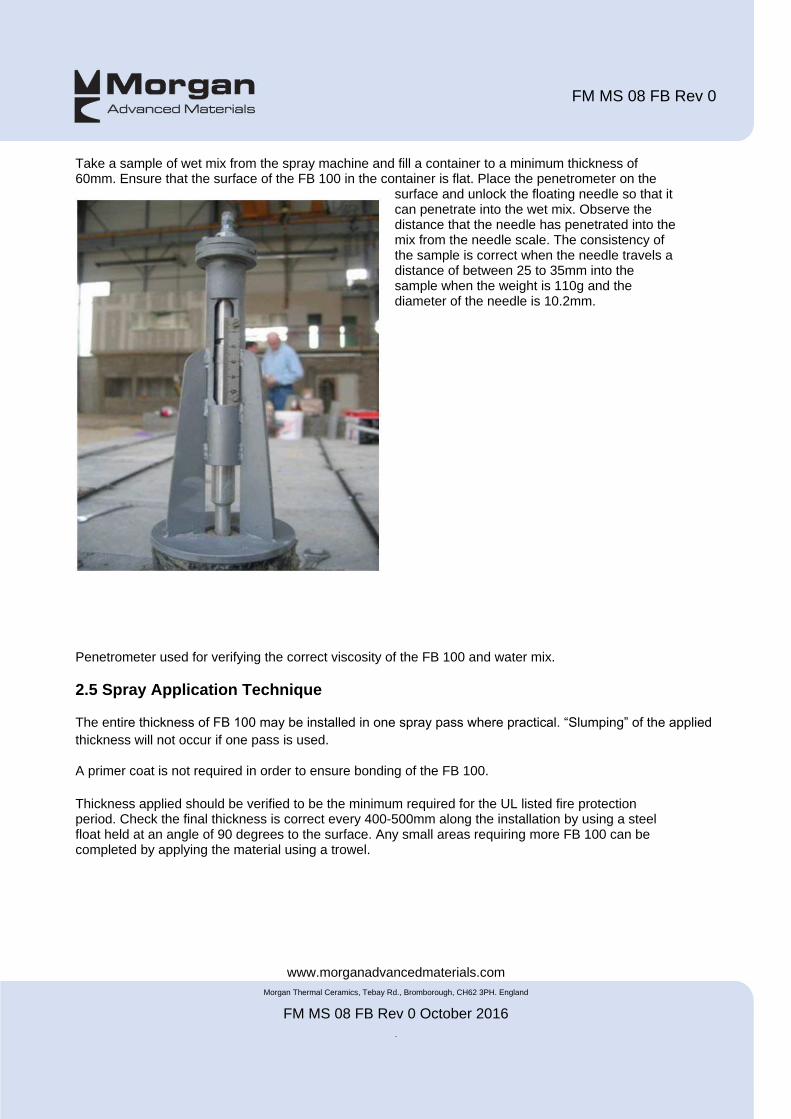
Take a sample of wet mix from the spray machine and fill a container to a minimum thickness of 60mm. Ensure that the surface of the FB 100 in the container is flat. Place the penetrometer on the
surface and unlock the floating needle so that it can penetrate into the wet mix. Observe the distance that the needle has penetrated into the mix from the needle scale. The consistency of the sample is correct when the needle travels a distance of between 25 to 35mm into the sample when the weight is 110g and the diameter of the needle is 10.2mm.
Penetrometer used for verifying the correct viscosity of the FB 100 and water mix.
2.5 Spray Application Technique
The entire thickness of FB 100 may be installed in one spray pass where practical. “Slumping” of the applied
thickness will not occur if one pass is used.
A primer coat is not required in order to ensure bonding of the FB 100.
Thickness applied should be verified to be the minimum required for the UL listed fire protection period. Check the final thickness is correct every 400-500mm along the installation by using a steel float held at an angle of 90 degrees to the surface. Any small areas requiring more FB 100 can be completed by applying the material using a trowel.
FM MS 08 FB Rev 0
www.morganadvancedmaterials.com
Morgan Thermal Ceramics, Tebay Rd., Bromborough, CH62 3PH. England
FM MS 08 FB Rev 0 October 2016
.
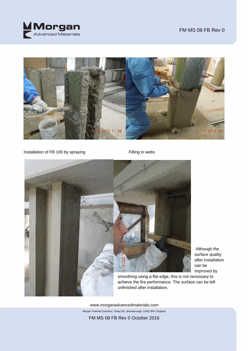
Installation of FB 100 by spraying Filling in webs
Although the
surface quality
after installation
can be
improved by
smoothing using a flat edge, this is not necessary to
achieve the fire performance. The surface can be left
unfinished after installation.
FM MS 08 FB Rev 0
www.morganadvancedmaterials.com
Morgan Thermal Ceramics, Tebay Rd., Bromborough, CH62 3PH. England
FM MS 08 FB Rev 0 October 2016
.
2.6 Quality Assurance During Installation
During each shift a sample of 300mm x 300mm x 50mm thick shall be prepared using the same mix as installed. The sample shall be marked with the date, product code taken from the packaging of the material being installed at the time of sampling and a reference denoting the area where the sampled mix was being installed when the sample was made. From this sample, sections of 50mm x 50mm square shall be taken on which the density will be verified by Morgan Thermal Ceramics to be within the following limits:
Property Morgan Thermal Ceramics test method
Accepted values
Density (after drying for 24 hrs @ 50 ºC)
C-MP-PF 217 813 kg/m³ minimum

FM MS 08 FB Rev 0
www.morganadvancedmaterials.com
Morgan Thermal Ceramics, Tebay Rd., Bromborough, CH62 3PH. England
FM MS 08 FB Rev 0 October 2016
.
3. Post-Installation Procedures
3.1 Inspection and Repair
Inspection
Inspect the surface at close distance to check for any large cracks (>2mm), or obvious signs of damage (areas
where material is missing or minimum required thickness has not been achieved). Hair-line cracks, as shown
below are acceptable as this is a normal consequence of expansion of the steel substrate.
Repair
For any areas requiring repair, the full lining thickness of FireMaster FB100 in that area must be replaced. Care should be taken when removing any faulty area not to damage the material in adjacent areas. Removal of FB100 can be carried out using a chisel or similar tool. The area to be repaired should be cleaned of all loose material and any other debris and the adjacent undamaged material surrounding the repair area wetted with water before any new FB is installed. Minor repairs can be made by trowelling FB into the repair area. Significant repairs should be made by spraying a new lining into place following the original installation procedures. If in doubt about the most appropriate repair method, contact Morgan Thermal Ceramics
END OF METHOD STATEMENT