hydrodynamics of narrow-tube fixed bed reactors filled
TRANSCRIPT

Delft University of Technology
Hydrodynamics of narrow-tube fixed bed reactors filled with Raschig rings
Moghaddam, E. M.; Foumeny, E. A.; Stankiewicz, A. I.; Padding, J. T.
DOI10.1016/j.cesx.2020.100057Publication date2020Document VersionFinal published versionPublished inChemical Engineering Science: X
Citation (APA)Moghaddam, E. M., Foumeny, E. A., Stankiewicz, A. I., & Padding, J. T. (2020). Hydrodynamics of narrow-tube fixed bed reactors filled with Raschig rings. Chemical Engineering Science: X, 5, [100057].https://doi.org/10.1016/j.cesx.2020.100057
Important noteTo cite this publication, please use the final published version (if applicable).Please check the document version above.
CopyrightOther than for strictly personal use, it is not permitted to download, forward or distribute the text or part of it, without the consentof the author(s) and/or copyright holder(s), unless the work is under an open content license such as Creative Commons.
Takedown policyPlease contact us and provide details if you believe this document breaches copyrights.We will remove access to the work immediately and investigate your claim.
This work is downloaded from Delft University of Technology.For technical reasons the number of authors shown on this cover page is limited to a maximum of 10.

Chemical Engineering Science: X 5 (2020) 100057
Contents lists available at ScienceDirect
Chemical Engineering Science: X
journal homepage: www.elsevier .com/locate /cesx
Hydrodynamics of narrow-tube fixed bed reactors filled with Raschigrings
https://doi.org/10.1016/j.cesx.2020.1000572590-1400/� 2020 The Author(s). Published by Elsevier Ltd.This is an open access article under the CC BY license (http://creativecommons.org/licenses/by/4.0/).
⇑ Corresponding author.E-mail address: [email protected] (E.M. Moghaddam).
E.M. Moghaddam ⇑, E.A. Foumeny, A.I. Stankiewicz, J.T. PaddingProcess & Energy Department, Delft University of Technology, the Netherlands
a r t i c l e i n f o
Article history:Received 8 September 2019Received in revised form 31 January 2020Accepted 1 February 2020
Keywords:Rigid Body DynamicsParticle – resolved CFD SimulationsFixed BedsRaschig ringsHydrodynamicsAzimuthal Averaging
a b s t r a c t
The local flow structure and pressure drop in random packings of Raschig rings are analyzed usingsequential Rigid Body Dynamics (RBD) method and Computational Fluid Dynamics (CFD) simulation.Tube-to-pellet diameter ratios, N, between 3 and 6 are investigated for laminar, transitional and turbu-lent flow regimes (5 � Rep � 3,000). The computed pressure drops are in good agreement with the empir-ical correlation of Nemec and Levec (2005), while the Ergun equation exhibited high deviations of morethan 60%, even when it is modified to explicitly account for non-sphericity of pellets. This deviation isascribed to additional sources for eddy formation offered by Rashig rings, compared to spheres and cylin-ders, which cannot be counterbalanced by the usage of a higher specific surface area. The 3D results offlow structure demonstrate a large influence of packing topology on the velocity distribution: rings ori-ented parallel to the flow accelerate the local velocity through their axial holes, while rings oriented per-pendicular to the flow provide additional space for vortex formation. The flow fields are substantiallydifferent from that found in packings of spheres and cylinders, both in terms of volume of backflowregions and velocity hotspots. This implies a higher order of local flow inhomogeneity in azimuthaland axial directions compared to spherical and cylindrical packings. Furthermore, it is found that azi-muthal averaging of the 3D velocity field over the bed volume, which has been used to improve classicalplug-flow pseudo-homogenous models to account for the role of tortuous velocity fields, cannot reflectthe appearance of vortex regions and thereby leads to underestimation of the local axial velocity valuesby over 500% of the inlet velocity.
� 2020 The Author(s). Published by Elsevier Ltd. This is an open access article under the CC BY license(http://creativecommons.org/licenses/by/4.0/).
1. Introduction
Tubular fixed bed reactors with a relatively low tube-to-pelletdiameter ratio N in the range of 2 to 10, are extensively employedin process and chemical industries due to their potential toenhance lateral heat transfer which is essential to prevent runawayreaction conditions and hot spot/cold spot formations. The designof such reactors is predominantly conducted using pseudo-homogenous models wherein the reactor environment is treatedas a quasi-homogenous medium. Conceptually, such modelsneglect the essential role of topological non-uniformities and localflow maldistributions, and often are used with the assumptions ofplug flow and equally distributed porosity throughout the bed. Inspite of numerous experimental and analytical research efforts toincorporate the effects of local flow and structural non-uniformities into these models, e.g. (Giese et al., 1998; Kwapinskiet al., 2004; Winterberg et al., 2000; Winterberg and Tsotsas,
2000a), even the most sophisticated models are still based uponlumped (effective) transport properties such as effective viscosity(Bey and Eigenberger, 2001; Kwapinski et al., 2004). The use ofsuch effective transport properties leads to failure of evenadvanced versions of pseudo-homogenous models, such as theso-calledKr(r) model which accounts for laterally uneven distribu-tions of porosity, axial velocity and effective thermal conductivity(Winterberg et al., 2000; Winterberg and Tsotsas, 2000a), for accu-rate prediction of transport scalars at the pellet-scale in low-Nfixed bed reactors. This failure can be attributed to the fact thatwhen only a few pellets fit in a tube cross-section, azimuthal sym-metry cannot be reasonably assumed (Dixon et al., 2006; Eppingeret al., 2011; Freund et al., 2005, 2003; Magnico, 2003; Nijemeislandand Dixon, 2004). Particle-resolved CFD simulations can offer adetailed insight into the role of spatial heterogeneity in thepellet-scale structure on the behavior of flow field and transportscalars (Dixon et al., 2012; Dong et al., 2017a; Singhal et al.,2017a). One of the pioneers in this direction were Derkx and Dixon(Derkx and Dixon, 1997), who conducted a 3D CFD simulation for asimple packed bed model with 3 spheres to obtain the wall heat

Nomenclature
do the outer diameter of rings [m]di the inner diameter of rings [m]dpv diameter of a sphere of equal volume [m]dps diameter of a sphere of equal specific surface area [m]dt tube or bed diameter [m]h height of pellet [m]I turbulence intensity [-]L bed length [m]N tube-to-pellet diameter ratio [-]Npv tube-to-pellet diameter ratio based on dpv [-]Nps tube-to-pellet diameter ratio based on dps [-]Rt bed radius [m]Rep Reynolds number based on dpv =qv0dpv=l [-]vo inlet velocity [m.s�1]
vz azimuthally-averaged axial velocity [m.s�1]Dp pressure drop [kg.m�1s�2]r radial Coordinate [m]z axial Coordinate [m]
Greek Letterse bulk porosity [-]e(r) radial porosity profile [-]d thickness of Raschig ring [mm]l fluid dynamic viscosity [kg.m�1s�1]q fluid phase density [kg.m�3]W dimensionless pressure drop introduced by Eq. (2) [-]
2 E.M. Moghaddam et al. / Chemical Engineering Science: X 5 (2020) 100057
transfer coefficient. Following this work, several research groupshave used different finite volume- or finite element-based CFDcodes to investigate the hydrodynamics and heat and mass transferin surrogate models of tubular fixed bed reactors. Most CFD studiesin the 2000s have been performed on small clusters of orderedpackings of mainly spherical pellets or periodic wall segment mod-els, which consist of a 120� slice of the bed cross-sectional area of afew layers of mostly spheres, see e.g. Dixon and coworkers (Dixonet al., 2008, 2006, 2005; Nijemeisland et al., 2004; Nijemeislandand Dixon, 2001; Taskin et al., 2008) and Guardo and coworkers(Coussirat et al., 2007; Guardo et al., 2007; 2005; 2004). Severalresearch groups have also combined computer-generated randompackings with particle-resolved CFD simulations of flow and trans-port scalars in tubular fixed beds (Atmakidis and Kenig, 2009; Baiet al., 2009; Boccardo et al., 2015; Dong et al., 2017a; Freund et al.,2005; Guo et al., 2019; Magnico, 2003). A detailed review on thenoted approaches for modeling random packing structures wasgiven by the present authors (Moghaddam et al., 2019). Forinstance, Magnico (2003) studied the influence of radial hetero-geneities of the granular structures on the local flow and radialmass transfer in packed tubes of spheres with N = 5.96 and 7.8at low to moderate particle Reynolds number, Rep from 7 to 200.In a similar work, Freund et al. (2005) have used Lattice Boltzmannsimulations to investigate the hydrodynamics and mass transfer intubes with spheres with N = 5.96 at Rep � 100. Similarly, Jafari et al.(2008), Atmakidis and Kenig (2009), Eppinger et al. (2011) andRobbins et al. (2012) have used computer-generated random pack-ings of spheres in CFD studies of hydrodynamics for a wide range ofRep. These studies have specifically focused on the influence of thewall on flow field and pressure drop in low-N packed beds ofspheres. Basically, majority of the existing discrete-pellet CFDstudies have addressed the problem of flow and heat transfer inspherical packing structures due to the simplicity of modellingthe packing process for such a pellet shape (Augier et al., 2010;Behnam et al., 2013; Dixon et al., 2012; Eppinger et al., 2011;Singhal et al., 2017a). There are few publications addressing flowand heat transfer in packed beds with non-spherical particles(Boccardo et al., 2015; Partopour and Dixon, 2017; Singhal et al.,2017; Wehinger et al., 2015a, 2015b). This scarcity can be ascribedto inherent difficulties with handling collisions between non-spherical pellets (Lu et al., 2015; Moghaddam et al., 2018; Seelenet al., 2018; Zhong et al., 2016). The prevailing discrete-pelletCFD studies that account for non-spherical pellets in fixed bedscan be classified into two main categories regarding the method-ologies adopted to synthesize packing structures: (1) sequentialDiscrete Element Method (DEM)-CFD approach, and (2) sequentialRigid Body Dynamics (RBD)-CFD approach. The former category,
i.e. DEM-CFD, frequently uses the so-called glued-sphere orcomposite-sphere method (Lu et al., 2015), wherein the generalframework of soft-sphere DEM is implemented to model shapedparticles and their collisions during the loading process.Wehinger et al. (2015) have used the glued-sphere method to per-form DEM-CFD simulations of flow, heat and reaction in packedtubes of spheres (dp = 4 mm), cylinders (dp/h = 5/5 mm) and Rashigrings (do/di/h = 6.2/3.5/4.5 mm) with N = 3.6 at relatively low Rep =60. They investigated the influence of different pellet designs onthe conversion and yield in dry reforming of methane. In anotherstudy, they dealt with the problem of contact point modificationin discrete-pellet CFD simulation of heat transfer in random pack-ing of cylinders with N = 4.04 and 191 < Rep < 743 (Wehinger et al.,2017). Dong et al. (2017) investigated the radial heat transfer in athin tube fixed bed stacked with glass spheres (dp = 3 mmwith 4 �N<7) and steatite rings (do/di/h = 6.2/3.5/4.5 mm with N = 3.4) formoderate flow conditions (60 < Rep h1 0 0) using the DEM-CFDmethod. The authors benchmarked their DEM-CFD results of heattransfer, e.g. the azimuthally-averaged temperature profile, againstexperimental data. Singhal et al. (2017b) have dealt with the prob-lem of fluid-to-particle heat transfer using particle resolved directnumerical simulation (PR-DNS). The authors used Star CCM+ 11.02,a commercial DEM package, to generate packed beds of cylinders(dp = 1 mm) with aspect ratio ranging from 2 to 6 using theglued-sphere method. Despite the promising outlook of DEM inhandling non-spherical particles (Lu et al., 2015; Rakotonirinaet al., 2018), the glued-sphere method, frequently used in DEM,depicted severe shortcomings, particularly in handling non-convex pellets (Lu et al., 2015; Zhong et al., 2016). For example,in the works of Wehinger et al. (2015) and Dong et al. (2017),the authors generated packing structures of Raschig rings by add-ing holes as a post-treatment to the final configuration of a DEM-generated packing of cylinders. This approach can only be accurateif the hole diameter is small enough such that the interpenetrationbetween Raschig rings does not affect the bulk porosity of the gen-erated structures.
There are a few studies that use sequential RBD-CFD to tackleflow and transport scalars in fixed beds of non-spherical particles.One of the pioneering works is the contribution of Boccardo et al.(2015), who used the open-source code Blender (a graphical soft-ware which uses the Bullet Physics Library) to synthesize packedbeds of different pellet shapes such as spheres, cylinders, and tri-lobes. Similarly, Partopour and Dixon (2017) have developed atailor-made integrated workflow using the Bullet Physics Libraryfor computational generation of randomly packed beds ofarbitrary-shaped pellets. The authors examined their automatedpackage for the analysis of flow and pressure drop in random pack-

Table 1RBD simulation parameters.
Parameters Preset Value
Pellet size [mm] do/di/h = 10/6/10Number of face mesh per pellet [#] 8008Pellet density [kg.m�3] 8030Tube size [mm] dt = 30.6, 40.5, 60.2; H = 150Number of pellets used for initialization [#] 59, 125, 285, depending on
dt
Surface friction coefficient of pellets (dynamic) 0.1Surface bounciness of pellets (COR*) 0.9Surface friction coefficient of tube walls
(dynamic)0.6
Surface bounciness of tube wall (COR*) 0.6Gravity acceleration [m s�2] 9.81Integration time step [s] 0.0025-0.025
* COR: Coefficient of Restitution.
E.M. Moghaddam et al. / Chemical Engineering Science: X 5 (2020) 100057 3
ings of spheres, cylinders, Raschig rings, and quadrilobes with fiveholes. Despite the existence of differences in the bulk porosity ofsphere packings in cylindrical beds predicted by Blender comparedto DigiDEM and LIGGGHTS, as reported by Fernengel et al. (2018),recently published results by Flaischlen and Wehinger (2019)demonstrate a better prediction of particle orientation insynthetically-generated packed columns of cylinders with Blenderthan Star-CCM+ software which uses the glued-sphere method tomodel non-spherical particles. The former authors underlined thatfurther studies with incorporation of experimental analysis areneeded in order to judge the accuracy of different collision meth-ods as well as the impacts of approximations necessary to stabilizethe simulations in the different approaches.
In our previous work (Moghaddam et al., 2019), we used oursequential RBD-CFD method (Moghaddam et al., 2018) to investi-gate packed beds with cylinders. This study addressed the impor-tance of topological heterogeneity, inadequacy of azimuthalaveraging, and the role of wall-effects on the velocity field andbed pressure drop. In this contribution, a similar study for Rashigrings, one of the most commonly-applied particle shapes in indus-try, is conducted. Here, tubular fixed beds containing Raschig ringswith N = 3.06, 4.05 and 6.02 are considered. Surprisingly, literatureinformation on Rashig rings is scarce, and available data only dealswith individual case studies. Therefore, to the authors’ knowledge,this is the first systematic numerical study of the porosity distribu-tion and flow properties in relatively narrow beds with Rashigrings.
Fig. 1. The RBD–simulated structures of Raschig rings with Npv = 3.06, 4.05, 6.02.
2. Methodology
2.1. RBD modeling of Raschig rings packing structures
The generation of 3D tubular beds packed with Raschig rings iscarried out using our recently published RBD-based random pack-ing algorithm, which employs a hard-body approach to handle col-lision phenomena. A detailed description together with a thoroughvalidation is given in the original paper (Moghaddam et al., 2018).In the current work, a preset number of Raschig rings pellets areplaced obliquely with an angle of 45� with respect to the gravitydirection in a column in line with the tube axis, mimicking a sockloading scheme (see Moghaddam et al., 2018, for more details), andfall under the influence of gravity to the bottom of the tube. Foreach of these rings, a force-torque balance together with other aux-iliary models accounting for pellet-pellet and (lateral and bottom)wall-pellet interactions, i.e. collisional contacts and resting con-tacts, are solved to simulate the random packing process. In ourmethodology, the transition between moving and resting particles,i.e. resting contact, is improved by a cutoff on sufficiently small rel-ative contact velocities, instead of artificially damping translationaland angular velocities during the entire filling process to stabilizethe packing simulation. The RBD simulation stops when a dynamicequilibrium is reached. Since the resulting porosity of the RBD-simulated structures is highly influenced by the physio-mechanical properties of pellets and container, tube-to-pelletdiameter ratio and the loading method, we pursued the setup pro-cedure reported in our previous work (Moghaddam et al., 2018) tosynthesize the densest possible random packings of Raschig rings.Table 1 gives details of the preset parameters used for the RBD-based simulations. Fig. 1 illustrates the results of RBD-simulatedpackings of Raschig rings with different N.
2.2. Computational domain and mesh generation
For the mesh generation, details of the RBD-generated struc-tures, i.e. the positions of the barycenters, the orientations and
the body face vertices of each Raschig ring, are imported to ANSYSWorkbench 16.2 to reproduce a CAD model of the packing struc-ture. A small interstice is then created between the pellets byshrinking each Raschig ring by 0.5% around its respective centerof mass, which prevents highly skewed cells in the contact regions.The size of the created gap is small enough to have a negligibleeffect on the bulk porosity of the packing, and to prevent jet forma-tion within the interstices even at high Rep conditions (Dixon et al.,2013). The minor influence of this post-treatment on the bulkporosity of the structures is addressed quantitatively in Section 3.1.In this work, an advanced meshing approach, based on a combina-tion of patch-independent and patch-conforming meshing meth-ods, is implemented to creat an inflation mesh topologycomprising of tetrahedral elements in the Raschig ring structures.This is conducted using an ad-hoc Python script in ANSYS Work-bench 16.2. Further details of the meshing method together withthe implementation of a graded meshing scheme in low-N packedcolumns, are presented in Moghaddam et al. (2019).
To achieve a precise prediction of the local velocity field in tur-bulent flow simulations, an appropriate mesh resolution isrequired, particularly in the contact regions. This was determinedvia a detailed mesh refinement study, in which the influence of dif-ferent grid sizes (both min and max mesh sizes in a graded mesh-ing scheme) and the number and thickness of prismatic layers onthe resulted y+ as well as local vector or scalar measurements,e.g. a vertex-averaged velocity along a line within the computa-tional domain, was analyzed. We refer to our recent work

Table 2Parameters used for mesh generation, and resulting mesh size for the RBD-simulatedstructures.
Meshing parameters Values
max mesh size do/18.2min mesh size (=gap size) do/200
growth rate in volume meshing 1.4 (including six inflation layers)initial height for boundary-layer
treatment2.5 � 10�4 do
number of layers for boundary-layertreatment
6
inflation rate used in boundary-layertreatment
1.2
thickness of boundary layer 2.48 � 10�3 do
N (dt/do) Particle count in CFD Model(up to H = 100 mm)
Total number of cells (�106)
3.06 51 11.684.05 100 26.356.03 251 46.90
4 E.M. Moghaddam et al. / Chemical Engineering Science: X 5 (2020) 100057
(Moghaddam et al., 2019), wherein a thorough mesh refinementanalysis has been performed for resolved-particle CFD study ofhydrodynamics in narrow-tube fixed beds of spheres and cylin-ders. According to our results, mesh independency can be appro-priately reached with the values presented in Table 2, and thuswe have implemented the same values in order to generate a
(a)
Fig. 2. Graded mesh topology in random packing of Raschig rings with N = 3.06; (a) f
graded mesh topology for the packing surrogates of Raschig rings.The final results of generated meshes, e.g. the total number of cells,are also given in Table 2. It is worth mentioning that the maximummesh size employed is comparable to those used in most othersimilar studies (Atmakidis and Kenig, 2009; Behnam et al., 2013;Ding et al., 2005; Dixon et al., 2012; Eppinger et al., 2011; Taskinet al., 2008). Fig. 2 exhibits how the proposed inflation-layer mesh-ing scheme results in finer cells at the contact regions. It is worthnoting that the prism thickness layer chosen is fine enough toobtain the recommended dimensionless wall distance y+ ofapproximately 1 according to the Enhanced Wall Treatment(EWT) approach.
2.3. CFD simulation setup
For the CFD simulations, the continuity and momentum equa-tions are solved using the finite volume code ANSYS Fluent 16.2for steady-state flow of an incompressible Newtonian fluid. Thefluid phase is assumed to be isothermal with the standard physicalproperties of air (q = 1.225 kg/m3, l = 1.7894�10�5 Pa.s). The airenters with a unidirectional and uniform velocity at the bottomof the system. This is introduced by a velocity-inlet boundary con-dition with the z-velocity component corresponding to the pelletReynolds number, Rep, ranging from 5 to 3.000, which is expressedby:
(b)
ace mesh on the tube wall, (b) a cut plane of the volume mesh at height z = 7dp.

Velocity Inlet
‘no-slip’ wall
Pressure-outletOutlet
Inlet
Extrusion 6dp
Extrusion 1dp
Flow Direc�on
Fig. 3. Schematic overview of a packing model of Raschig rings and boundaryconditions used in the CFD simulations; N = 4.05.
E.M. Moghaddam et al. / Chemical Engineering Science: X 5 (2020) 100057 5
Rep ¼ qv0;zdpvl
dpv ¼ffiffiffiffiffiffiffiffiffiffiffiffiffiffiffiffiffiffiffiffiffiffiffiffiffiffiffiffiffiffiffi1:5h d2
o � d2i
� �3
r ð1Þ
All solid surfaces, including the tube wall and the Raschig ringsurfaces, are defined as ‘no-slip’ boundaries. The tube outletboundary is set as a pressure-outlet condition with p = 1 bar. Fur-thermore, to minimize boundary effects, the bed entry and exit areextended by 1 and 6 pellet diameters, respectively. An overview ofthe flowmodel in conjunction with the preset boundary conditionsare given in Fig. 3. The CFD simulations are performed in the lam-inar (Rep � 100), transitional (100 < Rep < 600) and turbulent (Rep� 600) flow regimes, where the initial inlet turbulence intensity iscomputed based on the formula I = 0.16 Re�1/8 (where Re is basedon the hydraulic diameter).
To simulate fully-turbulent flow, i.e. for Rep � 600, the realiz-able k-e model with an Enhanced-Wall-Treatment (EWT) isemployed, which basically is a tried-and-tested RANS model forsimulating flow fields with strong streamline curvature, see e.g.(Dixon et al., 2012; Dong et al., 2017a; Eppinger et al., 2011). It isworth mentioning that both the (laminar) Navier-Stokes equationsand the realizable k-e model have been examined for CFD simula-tions in the transitional flow regime.
Table 3Bulk porosity results of RBD-generated packings of Raschig rings.
N (dt/d0) Npv (dt/dpv) Bulk porosity a
Simulated (before shrinkage)
3.06 3.1 0.6954.05 4.1 0.6416.02 6.1 0.601
*MRE: Mean Relative Error.
3. Results and discussion
3.1. Bulk and local bed porosities
The RBD-generated packings of Raschig rings are characterizedin terms of both global and radial porosity data. The bulk porosityof the simulated structures before and after bed shrinkage com-puted for the entire stack of Raschig rings up to the packing heightof 120 mm (the calculation procedure is explained in Moghaddamet al. (2018), and then compared with literature data in Table 3. Wenote that the height of 120 mm corresponds to two packing layersfrom the upper part to minimize the effect of loose structures atthe top part of the bed.
The results of the bulk porosity analysis demonstrate satisfac-tory agreement with the well-known empirical correlation pro-posed by Dixon (1988). Furthermore, the local shrinking ofRaschig rings by 0.5% of their nominal diameter results in minoralterations to the bulk porosities of the packing structures, of theorder of 0.7% to 1%, (see Table 3), which is reasonably small tonot significantly affect the bed hydrodynamics. It is worth notingthat the change in the computed bulk porosities of Raschig ringpackings due to the local contraction of 0.5% is approximately halfthe change in bulk porosities for random packings of spheres andsolid cylinders with the same N, reported in our previous study(Moghaddam et al., 2019).
Fig. 4 shows radial void fraction distribution obtained from theRBD-simulated structures versus wall distance, non-dimensionalized by the diameter of a volume-equivalent sphere.The results demonstrate influence of the tube wall on the orderingof the positions of Raschig rings along the tube radius. Such order-ing has been addressed by many researchers for random packingsof spheres and cylinders. However, as shown in Fig. 4, compared tothe radial porosity profiles of solid cylinders, the profiles forRaschig rings are characterized by a series of humps, which origi-nate from the axial holes in each pellet, repeating in a (damped-)oscillatory pattern towards the bed center. The position of the firstpeak in the vicinity of the tube wall is at the approximate distanceof 0.5dpv from the container wall, which, comparing to the positionof the first minimum in the radial void fraction profiles of fullcylinders of the same outer diameter do, is a little shifted towardsthe tube wall. This may be attributed to the size of inner hole insuch a pellet, as a higher hole-size would cause a higher changein the ordering of pellets at the near wall region compared witha full cylinder. Furthermore, the first hump starts at a distance ofd, extending over an approximate length of inner diameter di.The graphs also show that the gap distance between two neighborhumps is around 2d. It is worth remarking that the local porosity at(Rt-r)/dpv = 1.5 for random packing of Raschig rings with N = 3.06increases to 1 (as shown in Fig. 3), which evidences the presenceof a channel down the entire length of the tube. Such behaviorhas also been reported for packings of spheres and cylinders withNpv around 4, (Behnam et al., 2013). The emergence of an axialchannel in low-N packing structures is a consequence of restrictive
nalysis (based on packing structure up to H = 120 mm)
Dixon (1988) MRE* (%) Simulated (after shrinkage)
0.652 6.59 0.6990.626 2.43 0.6470.605 �0.77 0.607
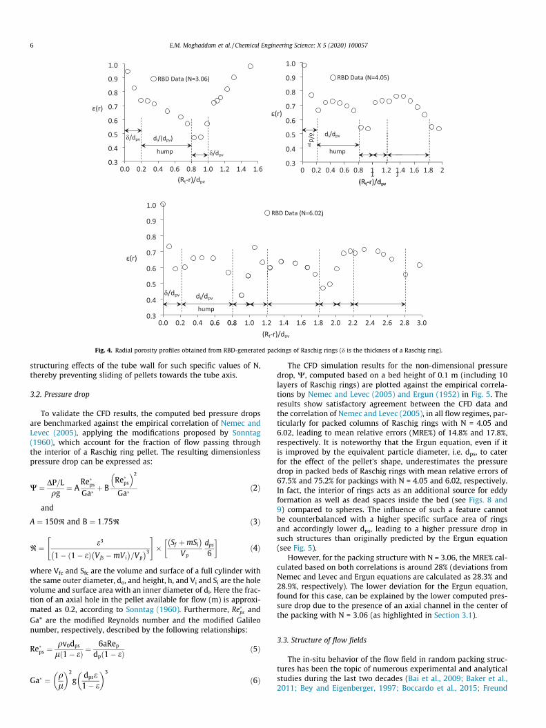
Fig. 4. Radial porosity profiles obtained from RBD-generated packings of Raschig rings (d is the thickness of a Raschig ring).
6 E.M. Moghaddam et al. / Chemical Engineering Science: X 5 (2020) 100057
structuring effects of the tube wall for such specific values of N,thereby preventing sliding of pellets towards the tube axis.
3.2. Pressure drop
To validate the CFD results, the computed bed pressure dropsare benchmarked against the empirical correlation of Nemec andLevec (2005), applying the modifications proposed by Sonntag(1960), which account for the fraction of flow passing throughthe interior of a Raschig ring pellet. The resulting dimensionlesspressure drop can be expressed as:
W ¼ DP=Lqg
¼ ARe�psGa�
þ BRe�ps
� �2
Ga�ð2Þ
and
A ¼ 150R and B ¼ 1:75R ð3Þ
R ¼ e3
1� 1� eð Þ Vfs �mVi� �
=Vp� �3
" #� Sf þmSi
� �Vp
dps
6
� �ð4Þ
where Vfc and Sfc are the volume and surface of a full cylinder withthe same outer diameter, do, and height, h, and Vi and Si are the holevolume and surface area with an inner diameter of di. Here the frac-tion of an axial hole in the pellet available for flow (m) is approxi-mated as 0.2, according to Sonntag (1960). Furthermore, Re�ps andGa* are the modified Reynolds number and the modified Galileonumber, respectively, described by the following relationships:
Re�ps ¼qv0dps
l 1� eð Þ ¼6aRep
dp 1� eð Þ ð5Þ
Ga� ¼ ql
2
gdpse1� e
3
ð6Þ
The CFD simulation results for the non-dimensional pressuredrop, W, computed based on a bed height of 0.1 m (including 10layers of Raschig rings) are plotted against the empirical correla-tions by Nemec and Levec (2005) and Ergun (1952) in Fig. 5. Theresults show satisfactory agreement between the CFD data andthe correlation of Nemec and Levec (2005), in all flow regimes, par-ticularly for packed columns of Raschig rings with N = 4.05 and6.02, leading to mean relative errors (MRE%) of 14.8% and 17.8%,respectively. It is noteworthy that the Ergun equation, even if itis improved by the equivalent particle diameter, i.e. dps, to caterfor the effect of the pellet’s shape, underestimates the pressuredrop in packed beds of Raschig rings with mean relative errors of67.5% and 75.2% for packings with N = 4.05 and 6.02, respectively.In fact, the interior of rings acts as an additional source for eddyformation as well as dead spaces inside the bed (see Figs. 8 and9) compared to spheres. The influence of such a feature cannotbe counterbalanced with a higher specific surface area of ringsand accordingly lower dps, leading to a higher pressure drop insuch structures than originally predicted by the Ergun equation(see Fig. 5).
However, for the packing structure with N = 3.06, the MRE% cal-culated based on both correlations is around 28% (deviations fromNemec and Levec and Ergun equations are calculated as 28.3% and28.9%, respectively). The lower deviation for the Ergun equation,found for this case, can be explained by the lower computed pres-sure drop due to the presence of an axial channel in the center ofthe packing with N = 3.06 (as highlighted in Section 3.1).
3.3. Structure of flow fields
The in-situ behavior of the flow field in random packing struc-tures has been the topic of numerous experimental and analyticalstudies during the last two decades (Bai et al., 2009; Baker et al.,2011; Bey and Eigenberger, 1997; Boccardo et al., 2015; Freund

Fig. 5. Comparison between the dimensionless pressure drops obtained from RBD-CFD simulations and empirical correlations for packings of Raschig rings with: (a) N = 3.06,(b) N = 4.05 and (c) N = 6.02.
E.M. Moghaddam et al. / Chemical Engineering Science: X 5 (2020) 100057 7
et al., 2003; Giese et al., 1998; Wehinger et al., 2017), as it has acrucial effect on local propagation of transport scalars inside thereactor, and, accordingly, on the reactor performance. However,as addressed in the introduction, only few studies deal with theflow structure inside a random packing of Raschig rings. In Fig. 6,two examples of the contour plots of axial velocity, normalizedby the inlet velocity, together with flow streamlines colored bythe axial velocity are illustrated for packed columns of Raschigrings with N = 3. 4.04 and 6.02 at a typical Rep = 00.
The contour plots of normalized axial velocity show significantinhomogeneity, both in the azimuthal (h-) direction at each cross-section and along the packing height. Furthermore, the contourplots at each cross section show the significance of Raschig ringorientation because the rings situated in parallel with the flowdirection can tremendously increase the local velocity throughtheir interiors.
Overall, the contour map reveals a local increase of axial veloc-ity up to factors of 5.81, 7.83 and 10.6 for packings of Raschig ringswith Npv = 3.1, 4.1 and 6.1, respectively, at Rep = 100. The local risein axial velocity increases with N at each specific Rep (as evidencedby the above-mentioned statistics for the maximum vz/v0 found inpackings with different Npv), which can be explained by thedecrease of the bulk porosity with increasing N. Similar resultsare found for the magnitude of negative z-velocity (e.g. vz/v0 =-1.08, -1.76 and -3.58 for N = 3.06, 4.05 and 6.02, respectively).
When comparing these results with our previous study on low-N fixed beds with spheres and cylinders (Moghaddam et al., 2019),it is found that the highest local increase of axial velocity occurs inpackings of cylinders, then spheres and then Raschig rings for sim-ilar Npv and Rep. For example, maximum vz/v0 values are 7.72, 7.24and 5.81, respectively, for packings of cylinders, spheres and ringswith Npv = 3.1 at Rep = 100, and maximum vz/v0 values are 12.02,
8.58 and 7.83, respectively, for packings of cylinders, spheres andrings with Npv = 4.1 at Rep = 100. The relatively lower local maximacan be attributed to the shape of Raschig rings pellets, where theexistence of an axial hole inside such pellets increases the localporosity. It is worth remarking that, contrary to the random pack-ings of spheres and cylinders wherein the high velocity fields arefound predominantly near the wall region (Dong et al., 2017a;Eppinger et al., 2011; Moghaddam et al., 2019; Wehinger et al.,2017), high velocity hotspots appear throughout the tube cross-section for Raschig ring packings, particularly at the interior partof pellets situated parallel to the flow direction. Furthermore, areaswith backflow appear inside the pellets located perpendicular tothe flow direction. These phenomena can be more clearly viewedvia the contours of axial velocity at the central plane (XZ plane)of the packings, as shown in Fig. 7.
As illustrated in Fig. 7a, maximum axial velocities occur at thecenter of the packing geometry with N around 3, which stems froma high local porosity near the tube center in such packing struc-tures. This circumstance can also be inferred from the radial poros-ity profile of this packing structure, as shown in Fig. 4. Severalresearchers have also reported similar observations for packingsof spheres with Npv around 4 (Behnam et al., 2013; Eppingeret al., 2011; Freund et al., 2003; Moghaddam et al., 2019), and alsofor cylinders with N slightly larger than 4 (Moghaddam et al.,2019). Furthermore, the contour plots reveal that areas with stag-nant and backflow velocity fields are not only emerging in thewakes of pellets, as observed for spheres and cylinders (Eppingeret al., 2011; Moghaddam et al., 2019), but are mostly appearinginside the rings situated perpendicular to the flow direction.
Fig. 8 highlights all fluid cells with stagnant and backflow fieldsin a random packing of Raschig rings with N = 4.05 at different Rep.As Fig. 8 shows, the volume fraction of such regions increases with

(a)
(0.5 dp) (2.5 dp) (4.5 dp)
(6.5 dp) (8.5 dp) (11.9 dp)
v ⁄
v ⁄ (0.5 dp) (4.5 dp)
(6.5 dp) (8.5 dp) (12.9 dp)
(2.5 dp)
v ⁄ (0.5 dp) (2.5 dp) (4.5 dp)
(6.5 dp) (8.5 dp) (12.9 dp)
(b)
(c)
Fig. 6. Examples of 3D flow fields using streamlines and contour plots of normalized axial velocity at different cross sections at axial positions 0.5dp, 2.5dp, 4.5dp, 6.5dp, 8.5dp
and +0.5dp behind the packing section, for packings of Raschig rings, with: (a) N = 3.06, (b) N = 4.03 and (b) N = 6.02 at Rep = 100.
8 E.M. Moghaddam et al. / Chemical Engineering Science: X 5 (2020) 100057

(a)
≥ 8.00
6.66
5.33
4.00
2.67
1.34
≤ 0.00
vz 0⁄ [−]
(b) (c)
Fig. 7. Contour plots of normalized axial velocity at the central plane (XZ) of packings with: (a) N = 3.06, (b) N = 4.05 and (c) N = 6.02 at Rep = 100.
(a) (b) (c)
-1.32
-1.10
-0.88
-0.66
-0.44
-0.22
0.00 v ⁄ [−]
-2.76
-2.30
-1.84
-1.38
-0.92
-0.50
0.00v ⁄ [−]
-2.81
-2.34
-1.87
-1.41
-94
-0.45
0.00 v ⁄ [−]
Fig. 8. Regions with stagnant and backflow velocity fields in a random packing of Raschig rings with N = 4.05; a) Rep = 10, b) Rep = 100 and c) Rep = 1000.
E.M. Moghaddam et al. / Chemical Engineering Science: X 5 (2020) 100057 9
increasing Rep, which implies the crucial role of eddy transport athigher flow conditions in fixed bed systems.
In Fig. 9, the volume fraction of fluid cells with stagnant andbackflow velocity fields are compared for random packings of
spheres, cylinders (these results were extracted from the resultsof our previous CFD study on spheres and cylinders, Moghaddamet al., 2019) and Raschig rings with Npv = 4.1 at different Rep values.The results demonstrate a higher volume fraction of backflow

Fig. 9. Volume fractions of fluid cells with stagnant and backflow velocity fields inrandom packings of spheres, cylinders and Raschig rings with Npv~4.1 for a packingheight of 0.1 m at different Rep.
10 E.M. Moghaddam et al. / Chemical Engineering Science: X 5 (2020) 100057
regions in a fixed bed of Raschig rings compared to spheres andcylinders with the same Npv, which arises from the presence of ahole inside each pellet, providing additional space for formationof vortices. Such a characteristic behavior offers a higher residencetime, as well as a better local mixing in the fluid phase, which alto-gether can enhance the transport rate at the pellet scale in fixedbeds of Raschig rings.
Fig. 10. Azimuthally–averaged axial velocity profiles at cross- sections z = 3.5dp,6dp and axially-azimuthally-averaged profile at Rep = 1000 together with the radialvoid fraction data for packings of Raschig rings with: (a) N = 3.06, (b) N = 4.04 and(c) N = 6.02.
3.4. Azimuthally-averaged velocity profiles
During the last two decades, several research groups havestrived to modify the earlier classical pseudo-homogenous plugflow models by introducing the velocity field in the form of a radi-ally varying axial velocity, vz(r) (Bey and Eigenberger, 2001; Dixonet al., 2006; Winterberg and Tsotsas, 2000b). Such a velocity fieldcan be obtained from a modified momentum balance or a formof Brinkman-Forcheimer-extended Darcy (BFD) equation (Beyand Eigenberger, 2001 & 1997; Giese et al., 1998). Comparisonsare made based on this modification and good agreement obtained,provided that an adjustable effective viscosity is introduced intothe term catering for wall effects, which depends on Rep, pelletshape, the assumed pressure drop correlation, and the porosity inthe near-wall region (Subagyo et al., 1998; Winterberg et al.,2000; Winterberg and Tsotsas, 2000). The axial velocity profile inthe form of vz(r) can also be obtained from CFD results by azi-muthal averaging of the 3D velocity field at different bed cross sec-tions. For instance, Fig. 10 illustrates the azimuthally-averagedaxial velocity distributions obtained from two different packingdepths and the axially-and-azimuthally-averaged profile togetherwith the radial porosity data for all packing models at Rep = 1000.
As shown in Fig. 10, the first maximum of the azimuthally-averaged axial velocities occurs adjacent to the tube wall and var-ies between 1.5 and 3 times the inlet superficial velocity, whichcorresponds to the values obtained by Bey and Eigenberger(1997) and Giese et al. (1998). Furthermore, Fig. 10a shows atremendous increase of averaged axial velocities at the bed center,which is attributed to the presence of a channel along the tube axisin Raschig ring packing with N = 3.06. The figure also demonstratesthat the first minimum of the global (axially-and-azimuthally-averaged) axial velocity profile takes place at approximately 0.85dpv
from the tube wall, corresponding to the first minimum in the localporosity profile, i.e. at the end of the first hump region. Comparedto the position of the first minima in global axial velocity profilesfor fixed beds of spheres and cylinders, which occur approximatelyat 0.5dpv and 0.65dpv from the tube wall (Behnam et al., 2013;
Eppinger et al., 2011; Freund et al., 2003; Moghaddam et al.,2019; Wehinger et al., 2017), this position shifts a little towardsthe bed center region for packings of Raschig rings. This may resultin a smoother trend of lateral dispersion of transport scalars insuch a packing structure. Nonetheless, a distinct differencebetween the local (azimuthally-averaged) and the global (axially-and-azimuthally-averaged) vz/v0 profiles can be observed, particu-larly at the points where the local porosity has its extreme values.Our results show that local deviations are stronger in narrowerstructures, e.g. N = 3.06, where azimuthal symmetry basically can-not be assumed, resulting in large inhomogeneity in vz(r) along thebed axis. For instance, Fig. 10a reveals that local azimuthally-averaged z-velocity at z = 6dp, i.e. vz(r,z = 6dp), deviates up to129% (with an average deviation of 27%) from the global (axially-and-azimuthally averaged) velocity vz(r) for a packing of Raschigrings with N = 3.05 at Rep = 1000. Similarly, Fig. 10b & c show devi-ations of up to 76% (with an average deviation of 17%) and up to68% (with an average deviation of 21%) for packings of Raschigrings with N = 4.06 and 6.02 at Rep = 1000, respectively.

E.M. Moghaddam et al. / Chemical Engineering Science: X 5 (2020) 100057 11
Overall, despite the fact that the results demonstrate an oscilla-tory pattern of the axially-and-azimuthally averaged axial velocityprofile along bed radius, contrary to the spherical and cylindricalcases (Atmakidis and Kenig, 2009; Eppinger et al., 2011;Moghaddam et al., 2019), it is hard to find a meaningful correlationbetween the global axial velocity profiles and the radial porositydistribution in random packings of Raschig rings.
The axially-and-azimuthally-averaged axial velocity profiles(solid lines) are compared with the azimuthally-averaged (dashedlines) and the in-situ axial velocity data (blue circles) in Fig. 11 at atypical cross section, z = 6dp, in Raschig rings packings with N =3.06 and 4.05 at Rep = 1000.
Overall, the results show a very high deviation of more than500% of the (axially-and-) azimuthally-averaged values of axialvelocities, even if obtained for a specific bed cross section, e.g.z = 6dp, from the local axial velocity values. Furthermore,Fig. 11 demonstrates that the maximum deviations (a localincrease of up to 13v0 with respect to the azimuthally-averaged axial velocity profile) occur approximately at the posi-tion of the first minimum in the axially-and-azimuthally-
Fig. 11. Axially-and-azimuthally–averaged axial velocity profiles (solid lines) compared wporosity data extracted at different positions (blue circles) at the cross-section z = 6dp f
averaged axial velocity profile, i.e. at the approximate distanceof 0.85dpv from the tube wall, which also corresponds to theposition of the first minimum in the radial porosity profile. Aremarkable difference between the local and azimuthally-averaged values of vz/v0 can be observed in the vicinity of thetube wall. Such noticeable deviations can result in erroneouspredictions of the apparent wall Nusselt number as Nuw / Re0:7p
and, accordingly, in the transverse wall heat flux, which can leadto an erroneous prediction of the temperature field in a highlyendothermic or exothermic reactions with very sharp tempera-ture gradients (where low-N tubular fixed beds are often used).The influence of azimuthal averaging of 3D velocity field on thedeviation of predicted radial temperature profile from 3D tem-perature field inside low-N tubular fixed beds will be investi-gated quantitatively in our forthcoming paper. Furthermore, asillustrated in Fig. 11, the azimuthally-averaged axial velocitiesare generally positive, while the actual local velocities can benegative, which substantiates the inadequacy of such averagedvelocity field information in reflecting the appearance of vortexregions, i.e. backflow as well as stagnant flow fields.
ith the azimuthally-averaged axial velocity profiles (dashed lines) and in-situ axialor Raschig ring packings with: (a) N = 3.06 and (b) N = 4.05, at Rep = 1000.

12 E.M. Moghaddam et al. / Chemical Engineering Science: X 5 (2020) 100057
4. Conclusions
Discrete-pellet CFD simulations of flow field and pressure dropin fixed beds of Raschig rings were conducted for a wide range ofRep values. For this, a tailor-made integrated workflow is employed(Moghaddam et al., 2019), which is based on the sequential gener-ation of the packing structures containing non-spherical pellets bymeans of our RBD-based random packing algorithm (Moghaddamet al., 2018), and the hydrodynamics using relevant CFD concepts.Overall, the methodology offers substantial improvements over theDEM-CFD approach in which a glued-sphere method is oftenapplied to synthesize random packings of non-convex pellets.
The CFD results have been validated by comparing the computedpressure drop to published empirical correlations. It is demon-strated that even an improved Ergun equation, which is modifiedby the equivalent particle diameter, dps, to account for the role ofthe pellet’s non-sphericity, underestimates the pressure drop infixed beds of Raschig rings significantly, e.g. leading to a mean rela-tive deviation of 75.2% for the packed column with N = 6.02 for theinvestigated range 5 < Rep < 3000. The reason for this deviation, asestablished here, is due to the contribution of additional sources ofvortex regions: the axial hole in Raschig rings in effect provides anadditional source for backflowfields inside a bed. The total pressuredrop cannot be counterbalanced by a higher specific surface area ofthe rings, which results in a higher pressure drop in such structuresthan originally predicted by the modified Ergun equation.
The 3D structures of the flow fields demonstrate a large influ-ence of local topology on the velocity distribution at the pelletscale. The contour plots of the axial velocity at different cross-sections reveal: (i) a remarkable inhomogeneity both in the azi-muthal direction at each cross section and along the packingheight, which directly stems from a strong spatial heterogeneityin such complicated topologies, and (ii) a significant influence ofRaschig ring orientation in the packing topology on local flow field,as the rings oriented in line with the flow direction can tremen-dously accelerate the local velocity through their axial holes, whilethose oriented perpendicular to the flow direction provide addi-tional sources for eddy formation.
The CFD results also show that azimuthal-averaging of the 3Dvelocity field along the packing structure not only cannot reflectthe areas with backflow field and vortex regions, but also leads toan error in the local velocity values of more than 500% of the inletsuperficial velocity. Thismight explain the inadequacy of evenmod-ified versions of pseudo-continuum approaches, wherein the globalazimuthally-averagedaxial velocityprofile is contributed toaccountfor the role of velocity field, in predicting the local transport scalarsinside such low-N fixed bed reactors. Of course, it is possible thattransport scalars such as temperature and concentration may notrespond to structural inhomogeneity as strongly as thevelocityfield.This will be the topic of our next work.
CRediT authorship contribution statement
E.M. Moghaddam: Conceptualization, Methodology, Software,Validation, Writing-original draft, Visualization, Funding acquisi-tion. E.A. Foumeny: Supervision, Writing-review & editing. A.I.Stankiewicz: Supervision, Resources, Project administration, Fund-ing acquisition. J.T. Padding: Supervision, Conceptualization,Resources, Writing-review & editing, Funding acquisition.
Declaration of Competing Interest
The authors declare that they have no known competing finan-cial interests or personal relationships that could have appearedto influence the work reported in this paper.
References
Atmakidis, T., Kenig, E.Y., 2009. CFD-based analysis of the wall effect on the pressuredrop in packed beds with moderate tube/particle diameter ratios in the laminarflow regime. Chem. Eng. J. 155, 404–410. https://doi.org/10.1016/j.cej.2009.07.057.
Augier, F., Idoux, F., Delenne, J.Y., 2010. Numerical simulations of transfer andtransport properties inside packed beds of spherical particles. Chem. Eng. Sci.65, 1055–1064. https://doi.org/10.1016/j.ces.2009.09.059.
Bai, H., Theuerkauf, J., Gillis, P.A., Witt, P.M., 2009. A coupled DEM and CFDsimulation of flow field and pressure drop in fixed bed reactor with randomlypacked catalyst particles. Ind. Eng. Chem. Res. 48, 4060–4074.
Baker, M.J., Young, P.G., Tabor, G.R., 2011. Image based meshing of packed beds ofcylinders at low aspect ratios using 3d MRI coupled with computational fluiddynamics. Comput. Chem. Eng. 35, 1969–1977. https://doi.org/10.1016/j.compchemeng.2011.03.017.
Behnam, M., Dixon, A.G., Nijemeisland, M., Stitt, E.H., 2013. A new approach to fixedbed radial heat transfer modeling using velocity fields from computational fluiddynamics simulations. Ind. Eng. Chem. Res. 52, 15244–15261. https://doi.org/10.1021/ie4000568.
Bey, O., Eigenberger, G., 2001. Gas flow and heat transfer through catalyst filledtubes. Int. J. Therm. Sci. 40, 152–164. https://doi.org/10.1016/S1290-0729(00)01204-7.
Bey, O., Eigenberger, G., 1997. Fluid flow through catalyst filled tubes 52.Boccardo, G., Augier, F., Haroun, Y., Ferre, D., Marchisio, D.L., 2015. Validation of a
novel open-source work-flow for the simulation of packed-bed reactors. Chem.Eng. J. 279, 809–820. https://doi.org/10.1016/j.cej.2015.05.032.
Coussirat, M., Guardo, A., Mateos, B., Egusquiza, E., 2007. Performance of stress-transport models in the prediction of particle-to-fluid heat transfer in packedbeds. Chem. Eng. Sci. 62, 6897–6907. https://doi.org/10.1016/j.ces.2007.08.071.
Derkx, O.R., Dixon, A.G., 1997. Effect of the wall Nusselt number on the simulationof catalytic fixed bed reactors. Catal. Today 35, 435–442. https://doi.org/10.1016/S0920-5861(96)00210-6.
Ding, Y., Wang, Z., Wen, D., Ghadiri, M., Fan, X., Parker, D., 2005. Solids behaviour ina gas – solid two-phase mixture flowing through a packed particle bed. Chem.Eng. Res. Des. 60, 5231–5239. https://doi.org/10.1016/j.ces.2005.04.052.
Dixon, A.G., 1988. Correlations for wall and particle shape effects on fixed bed bulkvoidage. Can. J. Chem. Eng. 66, 705–708. https://doi.org/10.1002/cjce.5450660501.
Dixon, A.G., Ertan Taskin, M., Nijemeisland, M., Stitt, E.H., 2008. Wall-to-particleheat transfer in steam reformer tubes: CFD comparison of catalyst particles.Chem. Eng. Sci. 63, 2219–2224. https://doi.org/10.1016/j.ces.2008.01.017.
Dixon, A.G., Nijemeisland, M., Stitt, E.H., 2013. Systematic mesh development for 3DCFD simulation of fixed beds: contact points study. Comput. Chem. Eng. 48,135–153. https://doi.org/10.1016/j.compchemeng.2012.08.011.
Dixon, A.G., Nijemeisland, M., Stitt, E.H., 2006. Packed tubular reactor modeling andcatalyst design using computational fluid dynamics. Adv. Chem. Eng. 31, 307–389. https://doi.org/10.1016/S0065-2377(06)31005-8.
Dixon, A.G., Nijemeisland, M., Stitt, E.H., 2005. CFD study of heat transfer near and atthe wall of a fixed bed reactor tube : effect of wall conduction. Ind Eng. Chem.Res. 44, 6342–6353.
Dixon, A.G., Walls, G., Stanness, H., Nijemeisland, M., Stitt, E.H., 2012. Experimentalvalidation of high Reynolds number CFD simulations of heat transfer in a pilot-scale fixed bed tube. Chem. Eng. J. 200–202, 344–356. https://doi.org/10.1016/j.cej.2012.06.065.
Dong, Y., Sosna, B., Korup, O., Rosowski, F., Horn, R., 2017. Investigation of radialheat transfer in a fixed-bed reactor: CFD simulations and profile measurements.Chem. Eng. J. 317, 204–214. https://doi.org/10.1016/j.cej.2017.02.063.
Eppinger, T., Seidler, K., Kraume, M., 2011. DEM-CFD simulations of fixed bedreactors with small tube to particle diameter ratios. Chem. Eng. J. 166, 324–331.https://doi.org/10.1016/j.cej.2010.10.053.
Ergun, S., 1952. Fluid flow through packed columns. Chem. Eng. Prog. 48, 89–94.Fernengel, J., von Seckendorff, J., Hinrichsen, O., 2018. Influence of cylinder-to-
particle diameter ratio and filling speed on bed porosity of random packed bedsof spheres. Computer Aid. Chem. Eng. Elsevier Masson SAS, 97–102. https://doi.org/10.1016/B978-0-444-64235-6.50019-X.
Flaischlen, S., Wehinger, G.D., 2019. Synthetic packed-bed generation for CFDsimulations: blender vs STAR-CCM+. Chem. Eng. 3 (52). https://doi.org/10.3390/chemengineering3020052.
Freund, H., Bauer, J., Zeiser, T., Emig, G., 2005. Detailed simulation of transportprocesses in fixed-beds. Ind. Eng. Chem. Res. 44, 6423–6434. https://doi.org/10.1021/ie0489453.
Freund, H., Zeiser, T., Huber, F., Klemm, E., Brenner, G., Durst, F., Emig, G., 2003.Numerical simulations of single phase reacting flows in randomly packed fixed-bed reactors and experimental validation. Chem. Eng. Sci. 58, 903–910. https://doi.org/10.1016/S0009-2509(02)00622-X.
Giese, M., Rottschafer, K., Vortmeyer, D., 1998. Measured and modeled superficialflow profiles in packed beds with liquid flow. AIChE J. 44, 484–490. https://doi.org/10.1002/aic.690440225.
Guardo, A., Coussirat, M., Larrayoz, M.A., Recasens, F., Egusquiza, E., 2005. Influenceof the turbulence model in CFD modeling of wall-to-fluid heat transfer inpacked beds. Chem. Eng. Sci. 60, 1733–1742. https://doi.org/10.1016/j.ces.2004.10.034.
Guardo, A., Coussirat, M., Larrayoz, M.A., Recasens, F., Egusquiza, E., 2004. CFD flowand heat transfer in nonregular packings for fixed bed equipment design. Ind.Eng. Chem. Res. 43, 7049–7056.
E.M. Moghaddam et al. / Chemical Engineering Science: X 5 (2020) 100057 13
Guardo, A., Coussirat, M., Recasens, F., Larrayoz, M.A., Escaler, X., 2007. CFD studieson particle-to-fluid mass and heat transfer in packed beds: Free convectioneffects in supercritical fluids. Chem. Eng. Sci. 62, 5503–5511. https://doi.org/10.1016/j.ces.2007.02.040.
Guo, Z., Sun, Z., Zhang, N., Ding, M., Zhou, Y., 2019. Influence of flow guiding conduiton pressure drop and convective heat transfer in packed beds. Int. J. Heat MassTransf. 134, 489–502. https://doi.org/10.1016/j.ijheatmasstransfer.2019.01.066.
Jafari, A., Zamankhan, P., Mousavi, S.M., Pietarinen, K., 2008. Modeling and CFDsimulation of flow behavior and dispersivity through randomly packed bedreactors. Chem. Eng. J. 144, 476–482. https://doi.org/10.1016/j.cej.2008.07.033.
Kwapinski, W., Winterberg, M., Tsotsas, E., Mewes, D., 2004. Modeling of the walleffect in packed bed adsorption. Chem. Eng. Technol. 27, 1179–1186. https://doi.org/10.1002/ceat.200407001.
Lu, G., Third, J.R., Müller, C.R., 2015. Discrete element models for non-sphericalparticle systems: From theoretical developments to applications. Chem. Eng.Sci. 127, 425–465. https://doi.org/10.1016/j.ces.2014.11.050.
Magnico, P., 2003. Hydrodynamic and transport properties of packed beds in smalltube-to-sphere diameter ratio: pore scale simulation using an Eulerian and aLagrangian approach. Chem. Eng. Sci. 58, 5005–5024. https://doi.org/10.1016/S0009-2509(03)00282-3.
Moghaddam, E.M., Foumeny, E.A., Stankiewicz, A.I., Padding, J.T., 2019. Fxed bedreactors of non-spherical pellets : Importance of heterogeneities andinadequacy of azimuthal averaging. Chem. Eng. Sci. X 1,. https://doi.org/10.1016/j.cesx.2019.100006 100006.
Moghaddam, E.M., Foumeny, E.A., Stankiewicz, A.I., Padding, J.T., 2018. Rigid bodydynamics algorithm for modeling random packing structures of nonsphericaland nonconvex pellets. Ind. Eng. Chem. Res. 57, 14988–15007. https://doi.org/10.1021/acs.iecr.8b03915.
Nemec, D., Levec, J., 2005. Flow through packed bed reactors: 1. Single-phase flow.Chem. Eng. Sci. 60, 6947–6957. https://doi.org/10.1016/j.ces.2005.05.068.
Nijemeisland, M., Dixon, A.G., 2004. CFD Study of fluid flow and wall heat transfer ina fixed bed of spheres. AIChE J. 50, 906–921. https://doi.org/10.1002/aic.10089.
Nijemeisland, M., Dixon, A.G., 2001. Comparison of CFD simulations to experimentfor convective heat transfer in a gas-solid fixed bed. Chem. Eng. J. 82, 231–246.https://doi.org/10.1016/S1385-8947(00)00360-0.
Nijemeisland, M., Dixon, A.G., Stitt, E.H., 2004. Catalyst design by CFD for heattransfer and reaction in steam reforming. Chem. Eng. Sci., 5185–5191 https://doi.org/10.1016/j.ces.2004.07.088.
Partopour, B., Dixon, A.G., 2017. An integrated workflow for resolved-particlepacked bed models with complex particle shapes. Powder Technol. 322, 258–272. https://doi.org/10.1016/j.powtec.2017.09.009.
Rakotonirina, A.D., Delenne, J.-Y., Radjai, F., Wachs, A., 2018. Grains3D, a flexibleDEM approach for particles of arbitrary convex shape—Part III: extension tonon-convex particles modelled as glued convex particles. Comput. Part. Mech.324, 1–30.
Robbins, D.J., El-Bachir, M.S., Gladden, L.F., Cant, R.S., von Harbou, E., 2012. CFDmodeling of single-phase flow in a packed bed with MRI validation. AIChE J. 58,3904–3915.
Seelen, L.J.H., Padding, J.T., Kuipers, J.A.M., 2018. A granular discrete elementmethod for arbitrary convex particle shapes: method and packing generation.Chem. Eng. Sci. 189, 84–101. https://doi.org/10.1016/j.ces.2018.05.034.
Singhal, A., Cloete, S., Radl, S., Quinta-Ferreira, R., Amini, S., 2017a. Heat transfer to agas from densely packed beds of monodisperse spherical particles. Chem. Eng. J.314, 27–37. https://doi.org/10.1016/j.cej.2016.12.124.
Singhal, A., Cloete, S., Radl, S., Quinta-Ferreira, R., Amini, S., 2017b. Heat transfer to agas from densely packed beds of cylindrical particles. Chem. Eng. Sci. 172, 1–12.https://doi.org/10.1016/j.ces.2017.06.003.
Sonntag, G., 1960. Einfluß des Lückenvolumens auf den Druckverlust ingasdurchströmten Füllkörpersäulen. Chemie Ing. Tech. 32, 317–329.
Standish Subagyo, N., Brooks, G.A., 1998. A new model of velocity distribution of asingle-phase fluid flowing in packed beds. Chem. Eng. Sci. 53, 1375–1385.https://doi.org/10.1016/S0009-2509(97)00444-2.
Taskin, M.E., Dixon, A.G., Nijemeisland, M., Stitt, E.H., 2008. CFD study of theinfluence of catalyst particle design on steam reforming reaction heat effects innarrow packed tubes. Ind. Eng. Chem. Res. 47, 5966–5975. 0.1021/ie800315d.
Wehinger, Gregor D., Eppinger, T., Kraume, M., 2015a. Evaluating catalytic fixed-bedreactors for dry reforming of methane with detailed CFD. Chemie-Ingenieur-Technik 87. https://doi.org/10.1002/cite.201400153.
Wehinger, Gregor D, Eppinger, T., Kraume, M., 2015b. Detailed numericalsimulations of catalytic fixed-bed reactors: Heterogeneous dry reforming ofmethane. Chem. Eng. Sci. 122, 197–209. https://doi.org/10.1016/j.ces.2014.09.007.
Wehinger, G.D., Füterer, C., Kraume, M., 2017. Contact modifications for CFDsimulations of fixed-bed reactors: Cylindrical particles. Ind. Eng. Chem. Res. 56,87–99. https://doi.org/10.1021/acs.iecr.6b03596.
Winterberg, Markus, Tsotsas, E., 2000a. Modelling of heat transport in beds packedwith spherical particles for various bed geometries and/or thermal boundaryconditions. Int. J. Therm. Sci. 39, 556–570. https://doi.org/10.1016/S1290-0729(00)00251-9.
Winterberg, Markus, Tsotsas, E., 2000b. Correlations for effective heat transportcoefficients in beds packed with cylindrical particles. Chem. Eng. Sci. 55, 5937–5943. https://doi.org/10.1016/S0009-2509(00)00198-6.
Winterberg, M., Tsotsas, E., 2000c. Impact of tube-to-particle-diameter ratio onpressure drop in packed beds. AIChE J. 46, 1084–1088. https://doi.org/10.1002/aic.690460519.
Winterberg, M., Tsotsas, E., Krischke, A., Vortmeyer, D., 2000. A simple and coherentset of coefficients for modelling of heat and mass transport with and withoutchemical reaction in tubes filled with spheres. Chem. Eng. Sci. 55, 967–979.https://doi.org/10.1016/S0009-2509(99)00379-6.
Zhong, W., Yu, A., Liu, X., Tong, Z., Zhang, H., 2016. DEM/CFD-DEM Modelling ofNon-spherical Particulate Systems: Theoretical Developments and Applications.Powder Technol. 302, 108–152. https://doi.org/10.1016/j.powtec.2016.07.010.
Further reading
Dixon, A.G., Nijemeisland, M., 2001. CFD as a design tool for fixed-bed reactors. Ind.Eng. Chem. Res., 5246–5254 https://doi.org/10.1021/ie001035a.
Mueller, G.E., 1993. Angular void fraction distributions in randomly packed fixedbeds of uniformly sized spheres in cylindrical containers. Powder Technol. 77,313–319. https://doi.org/10.1016/0032-5910(93)85023-3.