hydrogen manegment
TRANSCRIPT

8/12/2019 hydrogen manegment
http://slidepdf.com/reader/full/hydrogen-manegment 1/8
Hydrogen management
Reners are facing the challenge of meeting
increasingly higher quality product speci-
cations to make clean fuels product, while
at the same time purchasing lower-quality
H2-decient crudes. As a result, H
2 requirements
have been steadily increasing and reneries are
nding that proper H2 management is increas-
ingly important to their long-term viability.
This article will describe the process KBC has
successfully used to eliminate H2 availability
constraints and prioritise H2 use in order to
improve protability.
Increasing refinery complexity and H2
requirementsReneries have various levels of complexities
and operating objectives. The simplest renery
type is the hydroskimming renery. Figure 1
show a typical hydroskimming renery congu-
ration. Hydroskimming reneries typically do
not need a H2 plant, as the H
2 demand can be
adequately met by the naphtha reformer.Margins are often low at hydroskimming rener-
ies unless there is a large marketing advantage,
usually based on location.
Rick Manner KBC Advanced Technologies
It is typically advantageous to maximise the
production of higher-value transportation fuels
instead of lower-value fuel oil products. As a
result, most protable reneries are either
moderately complex or highly complex facilities
that have cracking and conversion units. H2
requirements can vary greatly from one congu-
ration to the next.
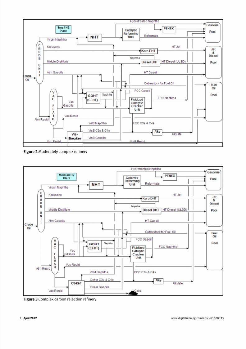
Figure 2 shows a typical conguration for a
moderately complex renery, which employs an
FCC and a visbreaking unit to increase product value. The addition of a gas oil hydrotreater for
the FCC feed increases the renery H2 demand
beyond what the reformer alone can provide. A
small H2 plant is therefore also needed.
Figure 3 shows a complex carbon rejection
renery. A coker is added to convert fuel oil to
more valuable products. Light coker gas oil is
hydrotreated in the diesel hydrotreater and
heavy coker gas oil is hydrotreated in the gas oil
hydrotreater. Now, a medium-sized H2 plant is
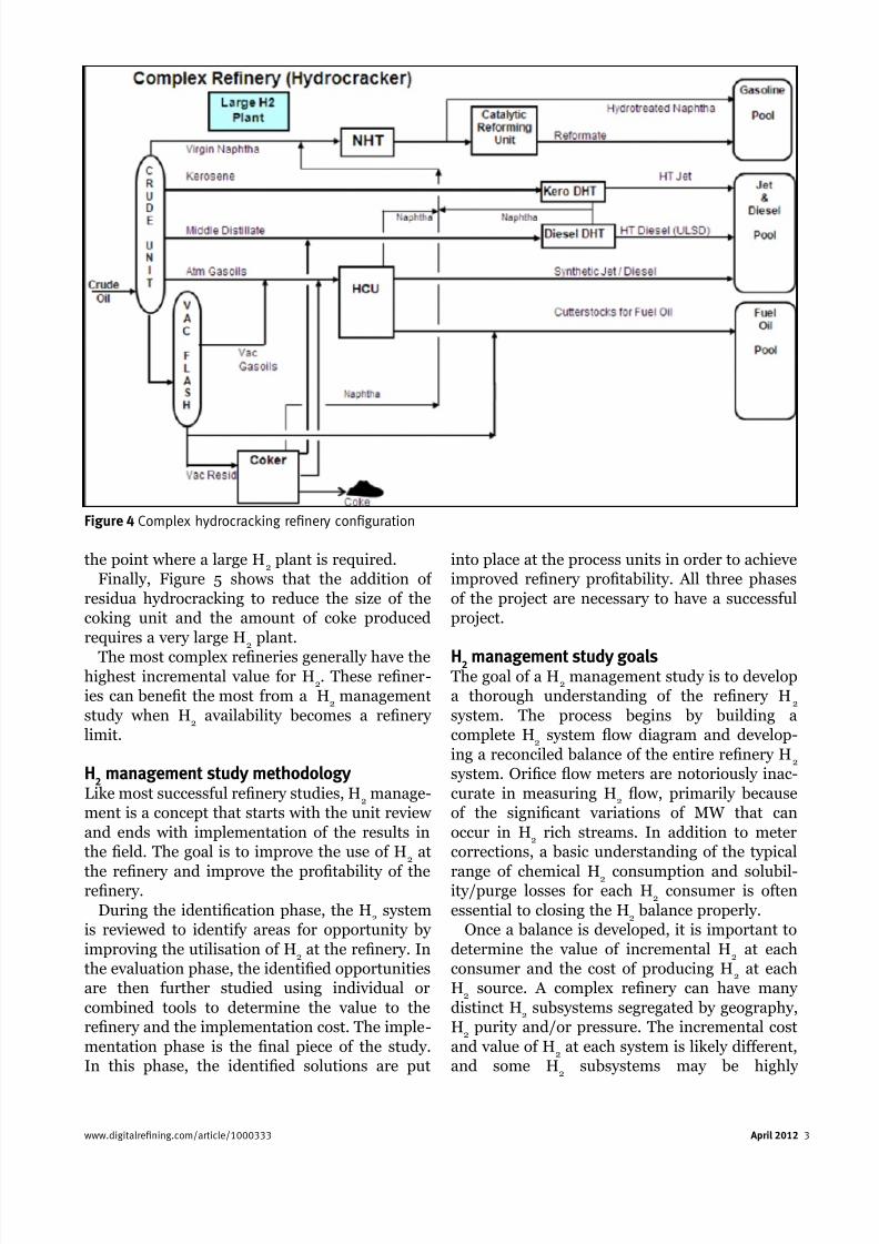
required.Figure 4 shows a complex hydrocracking ren-
ery conguration. Substituting a hydrocracker
for the FCC unit increases H2 requirements to
www.digitalrefining.com/article/1000333 April 2012 1
Figure 1 Hydroskimming refinery configuration
8/12/2019 hydrogen manegment
http://slidepdf.com/reader/full/hydrogen-manegment 2/8
2 April 2012 www.digitalrefining.com/article/1000333
Figure 2 Moderately complex refinery
Figure 3 Complex carbon rejection refinery
8/12/2019 hydrogen manegment
http://slidepdf.com/reader/full/hydrogen-manegment 3/8

8/12/2019 hydrogen manegment
http://slidepdf.com/reader/full/hydrogen-manegment 4/8
vulnerable to upsets that could be mitigated if
connections between isolated systems are
established.
The primary goal of a H2 management study is
to identify the constraints imposed by the overallsystem and various H
2 subsystems, and nd
ways to remove these constraints to improve
overall renery protability. Typical solutions
can be as simple as rerouting streams to maxim-
ise high-margin units at the expense of others or
more complex and capital intensive, such as
building H2 recovery units, debottlenecking
steam-methane reformers or installing additional
compression to provide additional exibility and
increase prots.
4 April 2012 www.digitalrefining.com/article/1000333
H2 management study tools
Renery H2 systems can be extremely complex.
As a result, it may be very difcult to evaluate all
of the possible H2 management opportunities
without the aid of specialised tools. KBC hasdeveloped two software products that are used in
our H2 management studies. The combination of
KBC’s HydrogenPinch and Petro-SIM software
is extremely effective in evaluating the value of
rerouting streams and/or removing constraints
in order to improve overall renery protability.
HydrogenPinch is KBC’s proprietary software
designed primarily to identify H2 system oppor-
tunities such as the optimal routing of H2
streams at a renery. This software evaluates the
Figure 5 Addition of residua hydrocracking
Figure 6 Study methodology diagram

8/12/2019 hydrogen manegment
http://slidepdf.com/reader/full/hydrogen-manegment 5/8

8/12/2019 hydrogen manegment
http://slidepdf.com/reader/full/hydrogen-manegment 6/8
example of this could be as simple as preferen-
tially sending lower-purity H2 streams to process
units like kerosene hydrotreaters that do not
require high purity to more complex opportuni-
ties to connect distinct separated H2 systems
based on purity, pressure or geography.
It is important to continue evaluating rerout-
ing options even after a more protable option is
found. An option is not necessarily the most
protable option just because it is an improve-
ment over the base case.
Recovering H2 from fuel gas is often a very
attractive recommendation from H2 management
studies. The most attractive technologies that
reneries typically use for this purpose are:• Pressure Swing Adsorption
• Membrane H2 recovery
• Feeding H2-rich streams to SMR H
2 plants to
recover H2.
Pressure Swing Adsorption
Pressure Swing adsorption (PSA) H2 purication
units produce a 99.9%+ purity H2 product typi-
cally from process streams containing 60-80%
H2 that would otherwise go into the renery fuel
gas system. The process uses proprietary adsorb-ents that capture essentially all non-H
2
compounds at system pressure (typically 250-
300 psig) and desorbs the adsorbed material to
fuel gas at very low pressures (typically 5 psig).
A PSA usually consists of 4-12 beds that alter-
nate between adsorption, depressuring and
purging to fuel. The pressuring and depressuring
sequences are optimised to minimise the amount
of H2 sent to fuel. Typical H
2 recoveries vary
between 80-90%.
PSA is a proven H2 recovery option
that is the clear choice when 99.9%+
H2 purity is required. The major
drawback to PSA H2 recovery units
is the cost of compressing the fuel
gas by-product. It is the clear
preferred choice in situations where
there is a large fuel gas user that can
accommodate low-pressure fuel gas
like a Steam Methane Reforming
(SMR) H2 plant furnace.
UOP and Linde are the two
primary suppliers of PSA technology.
Both licensors provide excellent
units that work well, although they
do not always achieve design H2
recovery. ExxonMobil and QuestAir have a
lower-cost version of the process called Rapid
Cycle PSA (RCPSA) that uses a rotating cylinder
instead of multiple beds and produces a lower-purity product at lower recoveries. There is a
niche application of this technology that allows
reners to improve recycle H2 purity at diesel
hydrotreating units that may make it a good
choice for some reneries.
Membrane H2 recovery
Membrane H2 recovery units operate based on
the difference in permeability between H2 and
the contaminants present in the H2 recovery
unit feed. The H2 permeates through amembrane and is recovered at a pressure that
is typically one-third of the inlet pressure. The
non-permeate gas contains about 10-15% of the
H2, and most of the non-H
2, and is available at
high enough pressure for fuel gas. The compo-
sition of permeate and non-permeate along the
membrane was calculated based on typical rela-
tive permeabilities of H2 and non-H
2
components. Based on these calculations, a
curve describing H2 recovery as a function of
permeates purity for three different feed puri-ties. Based on the location of the design point
near the bend in each curve, an operating curve
was developed to allow for estimation of H2
recovery and H2 purity at various feed qualities.
Figure 7 illustrates this relationship. Air
Products (PRISM), Air Liquide (Medal) and
UOP (PolySep) are major vendors of membrane
H2 recovery technology. A typical performance
curve for a membrane H2 recovery unit is shown
in Figure 7.
6 April 2012 www.digitalrefining.com/article/1000333
Figure 7 Typical performance curve of a membrane H2 recovery unit
8/12/2019 hydrogen manegment
http://slidepdf.com/reader/full/hydrogen-manegment 7/8
Membrane H2 recovery units
produce a lower-pressure H2
product and a high-pressure fuel
gas product. Membrane units are
a good choice for improving the
purity of high-pressure purge gas
off of a hydrotreater or hydroc-
racker and recycling the lower
pressure H2 to the make-up
compressor. If make-up compres-
sor capacity is not available, it is
more difcult to justify a
membrane H2 recovery unit
instead of a PSA.
Membrane H2 recovery is a
proven technology that has been
in continuous use in many ren-
eries for over 25 years. However,
membrane units cannot tolerate any liquids in
contact with the membranes and many renerieshave experienced this problem. In addition,
membrane units require some attention to start-
up or shutdown modules as conditions change as
run length progresses. They are not difcult to
operate, but the learning curve is much more
difcult than with a PSA
Route H2-rich feed to an SMR H
2 plant
H2 plants are excellent H
2 recovery units. H
2 in
H2 plant feeds typically appears as product at
very high recoveries and causes little or noincrease in red duty. Reners that have hydrau-
lic capacity should consider using their H2 plants
as H2 recovery units. Debottlenecking H
2 plants
is another option available that may be relatively
low cost for many H2 plants.
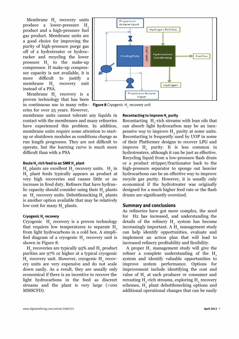
Cryogenic H2 recovery
Cryogenic H2 recovery is a proven technology
that requires low temperatures to separate H2
from light hydrocarbons in a cold box. A simpli-
ed diagram of a cryogenic H2 recovery unit isshown in Figure 8.
H2 recoveries are typically 95% and H
2 product
purities are 97% or higher at a typical cryogenic
H2 recovery unit. However, cryogenic H
2 recov -
ery units are very expensive and do not scale
down easily. As a result, they are usually only
economical if there is an incentive to recover the
light hydrocarbons in the feed as discreet
streams and the plant is very large (>100
MMSCFD).
Recontacting to improve H2 purity
Recontacting H2-rich streams with lean oils that
can absorb light hydrocarbon may be an inex-
pensive way to improve H2 purity at some units.
Recontacting is frequently used by UOP in some
of their Platformer designs to recover LPG and
improve H2 purity. It is less common in
hydrotreaters, although it can be just as effective.
Recycling liquid from a low-pressure ash drum
or a product stripper/fractionator back to the
high-pressure separator to sponge out heavier
hydrocarbons can be an effective way to improve
recycle gas purity. However, it is usually onlyeconomical if the hydrotreater was originally
designed for a much higher feed rate or the ash
drums are signicantly oversized.
Summary and conclusions As reneries have got more complex, the need
for H2 has increased, and understanding the
details of the renery H2 system has become
increasingly important. A H2 management study
can help identify opportunities, evaluate and
implement an action plan that will lead toincreased renery protability and exibility.
A proper H2 management study will give the
rener a complete understanding of the H2
system and identify valuable opportunities to
improve system performance. Options for
improvement include identifying the cost and
value of H2 at each producer or consumer and
rerouting H2-rich streams, exploring H
2 recovery
schemes, H2 plant debottlenecking options and
additional operational changes that can be easily
www.digitalrefining.com/article/1000333 April 2012 7
Figure 8 Cryogenic H2 recovery unit

8/12/2019 hydrogen manegment
http://slidepdf.com/reader/full/hydrogen-manegment 8/8
implemented to help maximise renery
protability.
Petro-SIM is a trademark of KBC Advanced Technologies plc, and
it is registered in various territories.
Rapid Cycle PSA (RCPSA) is a trademark of Exxon Mobil Corporation
and QuestAir and it is registered in various territories.
PRISM is a trademark f Air Products and it is registered in various
territories.Medal is a trademark of Air Liquide and it is registered in various
territories.
PolySep is a trademark of UOP and it is registered in various
territories.
8 April 2012 www.digitalrefining.com/article/1000333
Links
More artcle from: kBC Advaced Techologe
More artcle from the followg category:Hydroge Maagemet