hyperbolic metamaterials: new physics behind a classical
TRANSCRIPT

Hyperbolic metamaterials: new physics behind a classical problem
Vladimir P. Drachev,1,* Viktor A. Podolskiy,2 and Alexander V. Kildishev3 1Department of Physics and Center for Advanced Research & Technology, University of North Texas, Denton, TX
76203, USA 2Department of Physics and Applied Physics, University of Massachusetts Lowell, Lowell, MA 01854, USA
3Birck Nanotechnology Center and School of Electrical and Computer Engineering, Purdue University, West Lafayette, IN 47906, USA
Abstract: Hyperbolic materials enable numerous surprising applications that include far-field subwavelength imaging, nanolithography, and emission engineering. The wavevector of a plane wave in these media follows the surface of a hyperboloid in contrast to an ellipsoid for conventional anisotropic dielectric. The consequences of hyperbolic dispersion were first studied in the 50’s pertaining to the problems of electromagnetic wave propagation in the Earth’s ionosphere and in the stratified artificial materials of transmission lines. Recent years have brought explosive growth in optics and photonics of hyperbolic media based on metamaterials across the optical spectrum. Here we summarize earlier theories in the Clemmow’s prescription for transformation of the electromagnetic field in hyperbolic media and provide a review of recent developments in this active research area.
©2013 Optical Society of America
OCIS codes: (160.3918) Metamaterials; (160.1190) Anisotropic optical materials; (260.2110) Electromagnetic optics.
References and links
1. K. G. Budden, Radio Waves in the Ionosphere(Cambridge University, 1961). 2. P. Clemmow, “The theory of electromagnetic waves in a simple anisotropic medium,” Proc. IEEE 110(1), 101–
106 (1963). 3. L. B. Felsen and N. Marcuvitz, Radiation and Scattering of Waves (Wiley-IEEE, 1973). 4. R. H. Ritchie, “Plasma losses by fast electrons in thin films,” Phys. Rev. 106(5), 874–881 (1957). 5. S. M. Rytov, “Electromagnetic properties of a finely stratified medium,” Sov. Phys. JETP 2, 10 (1956). 6. D. R. Smith and D. Schurig, “Electromagnetic wave propagation in media with indefinite permittivity and
permeability tensors,” Phys. Rev. Lett. 90(7), 077405 (2003). 7. V. Bunkin, “On radiation in anisotropic media,” Sov. Phys. JETP 5(2), 277–283 (1957). 8. H. Kogelnik, “On electromagnetic radiation in magneto-ionic media,” J. Res. Nat. Bur. Stand. D. 64D, 515
(1960). 9. M. Born and E. Wolf, Principles of Optics(Cambridge University, 1999). 10. A. S. Potemkin, A. N. Poddubny, P. A. Belov, and Y. S. Kivshar, “Green function for hyperbolic media,” Phys.
Rev. A 86(2), 023848 (2012). 11. H. H. Kuehl, “Electromagnetic radiation from an electric dipole in a cold anisotropic plasma,” Plasma Phys.
Fluids 5(9), 1095 (1962). 12. K. G. Balmain, A. A. E. Luttgen, and P. C. Kremer, “Resonance cone formation, reflection, refraction, and
focusing in a planar anisotropic metamaterial,” IEEE Antennas Wirel. Propag. Lett. 1(1), 146–149 (2002). 13. Z. Jacob, L. V. Alekseyev, and E. Narimanov, “Optical hyperlens: far-field imaging beyond the diffraction
limit,” Opt. Express 14(18), 8247–8256 (2006). 14. A. Salandrino and N. Engheta, “Far-field subdiffraction optical microscopy using metamaterial crystals: theory
and simulations,” Phys. Rev. B 74(7), 075103 (2006). 15. Z. Liu, H. Lee, Y. Xiong, C. Sun, and X. Zhang, “Far-field optical hyperlens magnifying sub-diffraction-limited
objects,” Science 315(5819), 1686 (2007). 16. I. I. Smolyaninov, Y. J. Hung, and C. C. Davis, “Magnifying superlens in the visible frequency range,” Science
315(5819), 1699–1701 (2007).
#190862 - $15.00 USD Received 23 May 2013; revised 10 Jun 2013; accepted 10 Jun 2013; published 17 Jun 2013(C) 2013 OSA 17 June 2013 | Vol. 21, No. 12 | DOI:10.1364/OE.21.015048 | OPTICS EXPRESS 15048

17. W. Wang, H. Xing, L. Fang, Y. Liu, J. Ma, L. Lin, C. Wang, and X. Luo, “Far-field imaging device: planar hyperlens with magnification using multi-layer metamaterial,” Opt. Express 16(25), 21142–21148 (2008).
18. Y. Xiong, Z. Liu, and X. Zhang, “A simple design of flat hyperlens for lithography and imaging with half-pitch resolution down to 20 nm,” Appl. Phys. Lett. 94(20), 203108 (2009).
19. S. Thongrattanasiri and V. A. Podolskiy, “Hypergratings: nanophotonics in planar anisotropic metamaterials,” Opt. Lett. 34(7), 890–892 (2009).
20. L. Verslegers, P. B. Catrysse, Z. Yu, and S. Fan, “Deep-subwavelength focusing and steering of light in an aperiodic metallic waveguide array,” Phys. Rev. Lett. 103(3), 033902 (2009).
21. G. Ren, Z. Lai, C. Wang, Q. Feng, L. Liu, K. Liu, and X. Luo, “Subwavelength focusing of light in the planar anisotropic metamaterials with zone plates,” Opt. Express 18(17), 18151–18157 (2010).
22. C. Ma and Z. Liu, “A super resolution metalens with phase compensation mechanism,” Appl. Phys. Lett. 96(18), 183103 (2010).
23. G. Li, J. Li, and K. W. Cheah, “Subwavelength focusing using a hyperbolic medium with a single slit,” Appl. Opt. 50(31), G27–G30 (2011).
24. S. Ishii, A. V. Kildishev, E. Narimanov, V. Shalaev, and V. P. Drachev, “Sub-wavelength interference pattern from volume plasmon polaritons in a hyperbolic medium,” Laser Photonics Rev. 7(2), 265–271 (2013).
25. J. Kim, V. P. Drachev, Z. Jacob, G. V. Naik, A. Boltasseva, E. E. Narimanov, and V. M. Shalaev, “Improving the radiative decay rate for dye molecules with hyperbolic metamaterials,” Opt. Express 20(7), 8100–8116 (2012).
26. G. V. Naik, J. Liu, A. V. Kildishev, V. M. Shalaev, and A. Boltasseva, “Demonstration of Al:ZnO as a plasmonic component for near-infrared metamaterials,” Proc. Natl. Acad. Sci. U.S.A. 109(23), 8834–8838 (2012), doi:10.1073/pnas.1121517109.
27. A. J. Hoffman, L. Alekseyev, S. S. Howard, K. J. Franz, D. Wasserman, V. A. Podolskiy, E. E. Narimanov, D. L. Sivco, and C. Gmachl, “Negative refraction in semiconductor metamaterials,” Nat. Mater. 6(12), 946–950 (2007).
28. M. A. Noginov, H. Li, Y. A. Barnakov, D. Dryden, G. Nataraj, G. Zhu, C. E. Bonner, M. Mayy, Z. Jacob, and E. E. Narimanov, “Controlling spontaneous emission with metamaterials,” Opt. Lett. 35(11), 1863–1865 (2010).
29. R. J. Pollard, A. Murphy, W. R. Hendren, P. R. Evans, R. Atkinson, G. A. Wurtz, A. V. Zayats, and V. A. Podolskiy, “Optical nonlocalities and additional waves in epsilon-near-zero metamaterials,” Phys. Rev. Lett. 102(12), 127405 (2009).
30. J. Yao, Z. Liu, Y. Liu, Y. Wang, C. Sun, G. Bartal, A. M. Stacy, and X. Zhang, “Optical negative refraction in bulk metamaterials of nanowires,” Science 321(5891), 930 (2008).
31. J. Sun, J. Zhou, B. Li, and F. Kang, “Indefinite permittivity and negative refraction in natural material: graphite,” Appl. Phys. Lett. 98(10), 101901 (2011).
32. L. V. Alekseyev, V. A. Podolskiy, and E. E. Narimanov, “Homogeneous Hyperbolic Systems for Terahertz and Far-Infrared Frequencies,” Adv. Optoelectron. 2012, 267564 (2012).
33. E. Gerlach, P. Grosse, M. Rautenberg, and W. Senske, “Dynamical conductivity and plasmon excitation in Bi,” Phys. Status Solidi B 75(2), 553–558 (1976).
34. Y. Zhang, B. Fluegel, and A. Mascarenhas, “Total negative refraction in real crystals for ballistic electrons and light,” Phys. Rev. Lett. 91(15), 157404 (2003).
35. P. Belov, “Backward waves and negative refraction in uniaxial dielectrics with negative dielectric permittivity along the anisotropy axis,” Microw. Opt. Technol. Lett. 37(4), 259–263 (2003).
36. V. Veselago, “The electrodynamics of substances with simultaneously negative values of epsilon and mu,” Sov. Phys. Usp. 10(4), 509–514 (1968).
37. V. Podolskiy and E. Narimanov, “Strongly anisotropic waveguide as a nonmagnetic left-handed system,” Phys. Rev. B 71(20), 201101(R) (2005).
38. L. V. Alekseyev and E. Narimanov, “Slow light and 3D imaging with non-magnetic negative index systems,” Opt. Express 14(23), 11184–11193 (2006).
39. Y. Xiong, Z. Liu, and X. Zhang, “Projecting deep-subwavelength patterns from diffraction-limited masks using metal-dielectric multilayers,” Appl. Phys. Lett. 93(11), 111116 (2008).
40. J. B. Pendry, “Negative refraction makes a perfect lens,” Phys. Rev. Lett. 85(18), 3966–3969 (2000). 41. J. B. Pendry, “Perfect cylindrical lenses,” Opt. Express 11(7), 755–760 (2003). 42. S. A. Ramakrishna and J. B. Pendry, “Removal of absorption and increase in resolution in a near-field lens via
optical gain,” Phys. Rev. B 67(20), 201101 (2003). 43. N. A. Nicorovici, R. C. McPhedran, and G. W. Milton, “Optical and dielectric properties of partially resonant
composites,” Phys. Rev. B Condens. Matter 49(12), 8479–8482 (1994). 44. I. I. Smolyaninov, J. Elliott, A. V. Zayats, and C. C. Davis, “Far-field optical microscopy with a nanometer-scale
resolution based on the in-plane image magnification by surface plasmon polaritons,” Phys. Rev. Lett. 94(5), 057401 (2005).
45. R. K. Fisher and R. W. Gould, “Resonance cones in the field patterns of a short antenna in anisotropic plasma,” Phys. Rev. Lett. 22(21), 1093–1095 (1969).
46. S. Feng and J. M. Elson, “Diffraction-suppressed high-resolution imaging through metallodielectric nanofilms,” Opt. Express 14(1), 216–221 (2006).
#190862 - $15.00 USD Received 23 May 2013; revised 10 Jun 2013; accepted 10 Jun 2013; published 17 Jun 2013(C) 2013 OSA 17 June 2013 | Vol. 21, No. 12 | DOI:10.1364/OE.21.015048 | OPTICS EXPRESS 15049

47. P. A. Belov and Y. Hao, “Subwavelength imaging at optical frequencies using a transmission device formed by a periodic layered metal-dielectric structure operating in the canalization regime,” Phys. Rev. B 73(11), 113110 (2006).
48. D. Schurig and D. R. Smith, “Sub-diffraction imaging with compensating bilayers,” New J. Phys. 7, 162 (2005). 49. E. M. Purcell, “Spontaneous emission probabilities at radio frequencies,” Phys. Rev. 69, 681 (1946). 50. L. Novotny and B. Hecht, Principles of Nano-Optics (Cambridge University, 2006). 51. Z. Jacob, I. Smolyaninov, and E. Narimanov, “Broadband Purcell effect: radiative decay engineering with
metamaterials”, arXiv:0910.3981 [physics.optics]. 52. I. I. Smolyaninov and E. E. Narimanov, “Metric Signature Transitions in Optical Metamaterials,” Phys. Rev.
Lett. 105(6), 067402 (2010). 53. L. V. Alekseyev and E. Narimanov, Radiative decay engineering in metamaterials,” in Tutorials in
Metamaterials, ed. M.A. Noginov and V.A .Podolskiy (Taylor & Francis Group, 2012) pp. 209–223. 54. O. Kidwai, S. V. Zhukovsky, and J. E. Sipe, “Dipole radiation near hyperbolic metamaterials: applicability of
effective-medium approximation,” Opt. Lett. 36(13), 2530–2532 (2011). 55. A. N. Poddubny, P. A. Belov, and Y. S. Kivshar, “Spontaneous radiation of a finite-size dipole emitter in
hyperbolic media,” Phys. Rev. A 84(2), 023807 (2011). 56. B. Wood, J. Pendry, and D. Tsai, “Directed subwavelength imaging using a layered metal-dielectric system,”
Phys. Rev. B 74(11), 115116 (2006). 57. A. N. Poddubny, P. A. Belov, P. Ginzburg, A. V. Zayats, and Y. S. Kivshar, “Microscopic model of Purcell
enhancement in hyperbolic metamaterials,” Phys. Rev. B 86(3), 035148 (2012). 58. C. L. Cortes, W. Newman, S. Molesky, and Z. Jacob, “Quantum nanophotonics using hyperbolic metamaterials,”
J. Opt. 14(6), 063001 (2012). 59. S. I. Maslovski and M. G. Silveirinha, “Mimicking Boyer’s Casimir repulsion with a nanowire material,” Phys.
Rev. A 83(2), 022508 (2011). 60. O. Kidwai, S. V. Zhukovsky, and J. E. Sipe, “Effective-medium approach to planar multilayer hyperbolic
metamaterials: Strengths and limitations,” Phys. Rev. A 85(5), 053842 (2012). 61. H. N. Krishnamoorthy, Z. Jacob, E. Narimanov, I. Kretzschmar, and V. M. Menon, “Topological Transitions in
Metamaterials,” Science 336(6078), 205–209 (2012). 62. R. M. Bakker, V. P. Drachev, Z. Liu, H. K. Yuan, R. H. Pedersen, A. Boltasseva, J. Chen, J. Irudayaraj, A. V.
Kildishev, and V. M. Shalaev, “Nanoantenna array-induced fluorescence enhancement and reduced lifetimes,” New J. Phys. 10(12), 125022 (2008).
63. K. Drexhage, “Influence of a dielectric interface on fluorescence decay time,” J. Lumin. 1, 693–701 (1970). 64. W. Barnes, “Fluorescence near interfaces: the role of photonic mode density,” J. Mod. Opt. 45(4), 661–699
(1998). 65. G. Ford and W. Weber, “Electromagnetic interactions of molecules with metal surfaces,” Phys. Rep. 113(4),
195–287 (1984). 66. J. J. Burke, G. I. Stegeman, and T. Tamir, “Surface-polariton-like waves guided by thin, lossy metal films,”
Phys. Rev. B Condens. Matter 33(8), 5186–5201 (1986). 67. E. H. Hellen and D. Axelrod, “Fluorescence emission at dielectric and metal-film interfaces,” J. Opt. Soc. Am. B
4(3), 337–350 (1987). 68. G. Winter and W. L. Barnes, “Emission of light through thin silver films via near-field coupling to surface
plasmon polaritons,” Appl. Phys. Lett. 88(5), 051109 (2006). 69. J. B. Khurgin, G. Sun, and R. A. Soref, “Enhancement of luminescence efficiency using surface plasmon
polaritons: figures of merit,” J. Opt. Soc. Am. B 24(8), 1968–1980 (2007). 70. A. Govyadinov and V. Podolskiy, “Metamaterial photonic funnels for subdiffraction light compression and
propagation,” Phys. Rev. B 73(15), 155108 (2006). 71. M. Silveirinha and N. Engheta, “Tunneling of electromagnetic energy through subwavelength channels and
bends using ε-near-zero materials,” Phys. Rev. Lett. 97(15), 157403 (2006). 72. J. B. Pendry, D. Schurig, and D. R. Smith, “Controlling electromagnetic fields,” Science 312(5781), 1780–1782
(2006). 73. W. Cai, U. Chettiar, A. Kildishev, and V. Shalaev, “Optical cloaking with metamaterials,” Nat. Photonics 1(4),
224–227 (2007). 74. P. Yeh, A. Yariv, and C. Hong, “Electromagnetic propagation in periodic stratified media.I. General theory,” J.
Opt. Soc. Am. 67(4), 423 (1977). 75. A. P. Vinogradov, A. I. Ignatov, A. M. Merzlikin, S. A. Tretyakov, and C. R. Simovski, “Additional effective
medium parameters for composite materials (excess surface currents),” Opt. Express 19(7), 6699–6704 (2011). 76. V. Agranovich and V. Kravtsov, “Notes on crystal optics of superlattices,” Solid State Commun. 55(1), 85–90
(1985). 77. S. I. Pekar, “The theory of electromagnetic waves in crystal in which excitons are produced,” Sov. Phys. JETP 6,
785–796 (1958). 78. G. A. Wurtz, R. Pollard, W. Hendren, G. P. Wiederrecht, D. J. Gosztola, V. A. Podolskiy, and A. V. Zayats,
“Designed ultrafast optical nonlinearity in a plasmonic nanorod metamaterial enhanced by nonlocality,” Nat. Nanotechnol. 6(2), 107–111 (2011).
#190862 - $15.00 USD Received 23 May 2013; revised 10 Jun 2013; accepted 10 Jun 2013; published 17 Jun 2013(C) 2013 OSA 17 June 2013 | Vol. 21, No. 12 | DOI:10.1364/OE.21.015048 | OPTICS EXPRESS 15050
79. P. A. Belov, R. Marqués, S. I. Maslovski, I. S. Nefedov, M. Silverinha, M. Simovski, and S. A. Tretyakov, “Strong spatial dispersion in wire media in the very large wavelength limit,” Phys. Rev. B 67(11), 113103 (2003).
80. A. Chebykin, A. Orlov, A. Vozianova, S. Maslovski, Y. Kivshar, and P. Belov, “Nonlocal effective medium model for multilayered metal-dielectric metamaterials,” Phys. Rev. B 84(11), 115438 (2011).
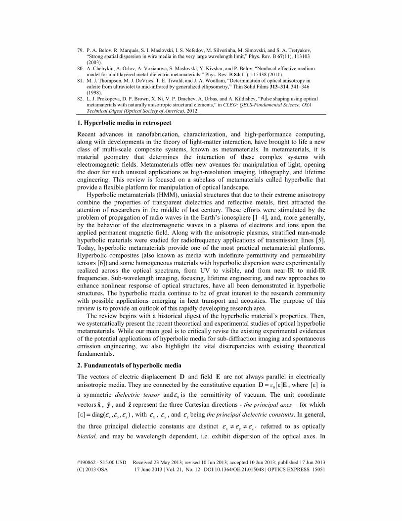
81. M. J. Thompson, M. J. DeVries, T. E. Tiwald, and J. A. Woollam, “Determination of optical anisotropy in calcite from ultraviolet to mid-infrared by generalized ellipsometry,” Thin Solid Films 313–314, 341–346 (1998).
82. L. J. Prokopeva, D. P. Brown, X. Ni, V. P. Drachev, A. Urbas, and A. Kildishev, “Pulse shaping using optical metamaterials with naturally anisotropic structural elements,” in CLEO: QELS-Fundamental Science, OSA Technical Digest (Optical Society of America), 2012.
1. Hyperbolic media in retrospect
Recent advances in nanofabrication, characterization, and high-performance computing, along with developments in the theory of light-matter interaction, have brought to life a new class of multi-scale composite systems, known as metamaterials. In metamaterials, it is material geometry that determines the interaction of these complex systems with electromagnetic fields. Metamaterials offer new avenues for manipulation of light, opening the door for such unusual applications as high-resolution imaging, lithography, and lifetime engineering. This review is focused on a subclass of metamaterials called hyperbolic that provide a flexible platform for manipulation of optical landscape.
Hyperbolic metamaterials (HMM), uniaxial structures that due to their extreme anisotropy combine the properties of transparent dielectrics and reflective metals, first attracted the attention of researchers in the middle of last century. These efforts were stimulated by the problem of propagation of radio waves in the Earth’s ionosphere [1–4], and, more generally, by the behavior of the electromagnetic waves in a plasma of electrons and ions upon the applied permanent magnetic field. Along with the anisotropic plasmas, stratified man-made hyperbolic materials were studied for radiofrequency applications of transmission lines [5]. Today, hyperbolic metamaterials provide one of the most practical metamaterial platforms. Hyperbolic composites (also known as media with indefinite permittivity and permeability tensors [6]) and some homogeneous materials with hyperbolic dispersion were experimentally realized across the optical spectrum, from UV to visible, and from near-IR to mid-IR frequencies. Sub-wavelength imaging, focusing, lifetime engineering, and new approaches to enhance nonlinear response of optical structures, have all been demonstrated in hyperbolic structures. The hyperbolic media continue to be of great interest to the research community with possible applications emerging in heat transport and acoustics. The purpose of this review is to provide an outlook of this rapidly developing research area.
The review begins with a historical digest of the hyperbolic material’s properties. Then, we systematically present the recent theoretical and experimental studies of optical hyperbolic metamaterials. While our main goal is to critically revise the existing experimental evidences of the potential applications of hyperbolic media for sub-diffraction imaging and spontaneous emission engineering, we also highlight the vital discrepancies with existing theoretical fundamentals.
2. Fundamentals of hyperbolic media
The vectors of electric displacement D and field E are not always parallel in electrically anisotropic media. They are connected by the constitutive equation 0[ε]= EeD , where [ε] is
a symmetric dielectric tensor and 0ε is the permittivity of vacuum. The unit coordinate
vectors x , y , and z represent the three Cartesian directions - the principal axes – for which
x y z[ε] diag( , , )ε ε ε= , with xε , yε , and zε being the principal dielectric constants. In general,
the three principal dielectric constants are distinct x y zε ε ε≠ ≠ referred to as optically
biaxial, and may be wavelength dependent, i.e. exhibit dispersion of the optical axes. In
#190862 - $15.00 USD Received 23 May 2013; revised 10 Jun 2013; accepted 10 Jun 2013; published 17 Jun 2013(C) 2013 OSA 17 June 2013 | Vol. 21, No. 12 | DOI:10.1364/OE.21.015048 | OPTICS EXPRESS 15051

optically uniaxial media, where x yε ε ε= = , and zε ε≠ , the principal direction z must
coincide with the optic axis, which typically defines the three-fold, four-fold or six-fold axial symmetry of a given crystal, so that ( )z[ε] diag , ,ε ε ε= .
While in crystal optics a uniaxial medium corresponds to a wide class of crystalline structures with mainly elliptic dispersion, for magneto-ionic media it specifies the medium with an infinitely strong magnetostatic field bias [2], which, similar to hyperbolic metamaterials, can also have different signs of the principal dielectric constants, e.g. 0ε > ,
z 0ε < .Here, we restrict ourselves to uniaxial hyperbolic media, as the main known
theoretical analyses have been done for the hyperbolic uniaxial plasmas in [3, 7, 8].
2.1 Clemmow’s prescriptions
Anisotropy of material constants results in a transformation of the electromagnetic field distribution in space under diffraction or point source radiation. Because of the foreseeable complexity of the general analysis presented in [3, 7, 8] we review the Clemmow approach [2] and isolate the simple cases of TM and TE waves in hyperbolic plasma, which are then applied to the refraction and diffraction of light in novel artificial hyperbolic media. The analysis in [2] is restricted to a media of unit permeability, and starts with known E- and H-fields in free space (denoted respectfully as 0 0( )E r and 0 0( )H r ), with 0 0 0 0ˆ ˆ ˆx y z= + +r x y z
defining an observation point. Then, the scaling procedure 0E(r) = [e]E ([n]r) and 0H(r) = [h]H ([n]r) is derived to find the corresponding fields, ( )E r and ( )H r in a given
uniaxial media, where , ,[e] [n] and [h] are linear transforms. The above procedure is
impossible unless one of the z-components of either 0H or 0E is dropped, leading to solutions valid solely for either transverse magnetic (TM, 0ˆ 0⋅ =z H ) or transverse electric
(TE, 0ˆ 0⋅ =z E ) waves. From the symmetry considerations for TM-waves it follows that the metric and the E-field
scaling transforms repeat the structure of the dielectric tensor, ( )z[ε] diag , , ,ε ε ε= so that
( )z[e] diag , , ,e e e= and, while the transverse components of H-field are scaled uniformly, i.e.
[ ] [ ],h=h i where [ ]i is the identity matrix. From the Maxwell curl equations for the TM
waves, it then follows that 1 1 1z[ ] [ ] [ε]nn h− − −=n s and 1
z[ ] [ ] [ε],nn h− =n s or 1z[ ][ ] [ε].ee h− =n e
Multiplying the above equations we first arrive at 2 2z ,n e ε= = 2 2
z zn e ε= = , and 2zh εε= ,
and then, at the remarkably simple Clemmow’s TM-prescription
( ) [ ] [ ]( ) ( ) [ ]0 0, ( ),zεε= =E r n E n r H r H n r (1)
where ( )z z[ ] diag , ,ε ε ε=n .
In contrast, for TE-waves it can be expected that since 0ˆ 0,⋅ =z E then zε should not
appear in the Maxwell equations for the uniaxial medium, as if that medium were isotropic
with dielectric constant zε . Indeed, the final Clemmow’s TE-prescription is, ( )n ε=
( ) ( ) ( )0 0, ( ).n n n= =E r E r H r H r (2)
2.2 Dispersion relations in a uniaxial hyperbolic medium
Consider the behavior of monochromatic plane waves in uniaxial hyperbolic media before addressing the complex fields generated there by elementary sources. Following the general
#190862 - $15.00 USD Received 23 May 2013; revised 10 Jun 2013; accepted 10 Jun 2013; published 17 Jun 2013(C) 2013 OSA 17 June 2013 | Vol. 21, No. 12 | DOI:10.1364/OE.21.015048 | OPTICS EXPRESS 15052
Clemmow approach, the space-time dependence ( ) ( ); exp cf t tωι ω = ⋅ − r k r is taken here
for a plane wave defined for a given angular frequencyω and the free-space speed of light c
using the material wavevector [ ] 0=k n k with the freespace wave-vector 0k ( )0 1=k . Then,
the phase velocity of the plane wave is p .v c= k A plane wave [9] in a uniaxial media splits
into two linearly polarized characteristic waves: ordinary waves for which the E-vector is normal to the principal plane, which contains both the wave vector and the optic axis, ,z and extraordinary waves with E-vector parallel to the principal plane. For ordinary waves, E is aligned with D, and the phase velocity is independent of propagation direction. As any free-space electromagnetic field can be represented as a superposition of coplanar TM- and TE-waves, there is always a matching superposition of coplanar TM- and TE-waves in the uniaxial medium obtained from the scaling transformations (1) and (2). These transformations are also reversible, since a representation of any uniaxial-medium field as a superposition of coplanar TM- and TE-waves is always possible. For example, the independent characteristic extraordinary (TM) and ordinary (TE) plane waves in the anisotropic medium are obtained from the corresponding free-space plane waves in [2].
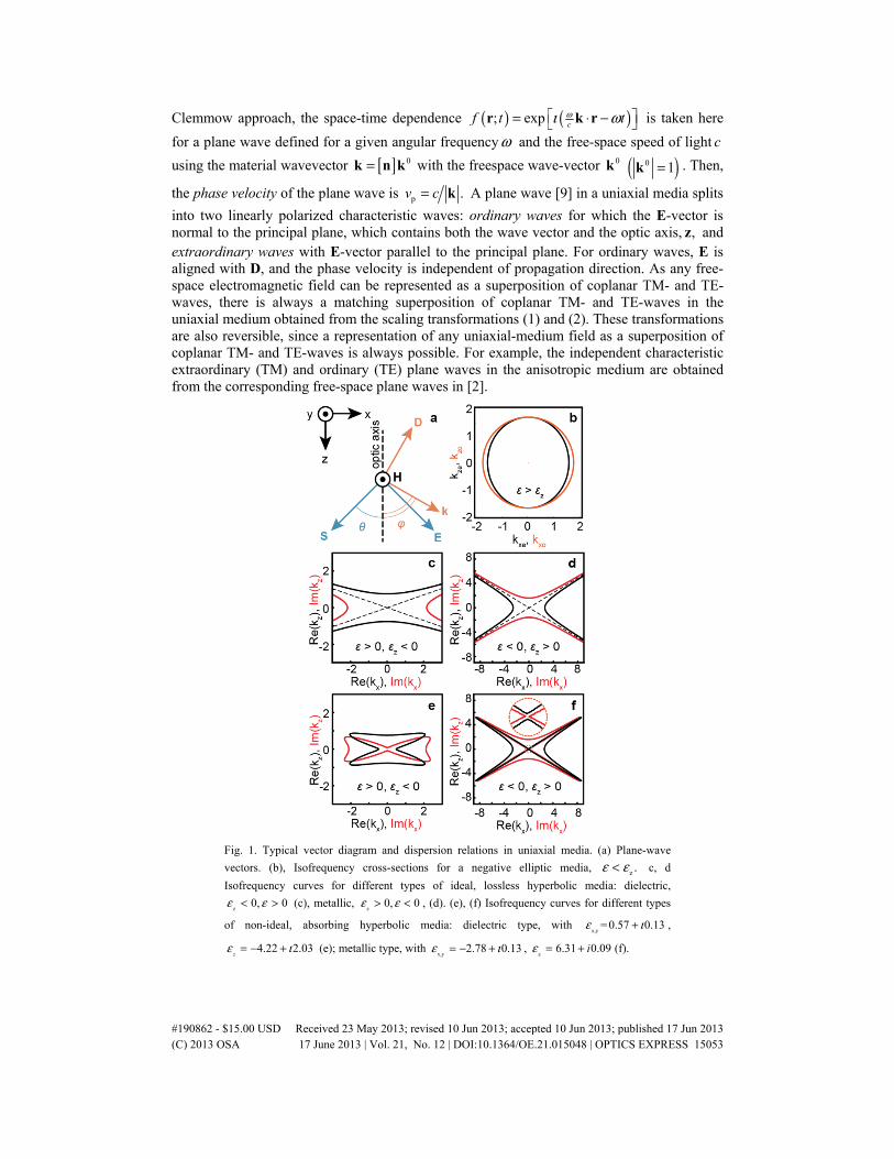
Fig. 1. Typical vector diagram and dispersion relations in uniaxial media. (a) Plane-wave
vectors. (b), Isofrequency cross-sections for a negative elliptic media, z .ε ε< c, d
Isofrequency curves for different types of ideal, lossless hyperbolic media: dielectric,
z0, 0ε ε< > (c), metallic,
z0, 0ε ε> < , (d). (e), (f) Isofrequency curves for different types
of non-ideal, absorbing hyperbolic media: dielectric type, with x,y
= 0.57 0.13ε ι+ ,
4.22 2.03z
ε ι= − + (e); metallic type, with x,y
2.78 0.13ε ι= − + , z
6.31 0.09iε = + (f).
#190862 - $15.00 USD Received 23 May 2013; revised 10 Jun 2013; accepted 10 Jun 2013; published 17 Jun 2013(C) 2013 OSA 17 June 2013 | Vol. 21, No. 12 | DOI:10.1364/OE.21.015048 | OPTICS EXPRESS 15053

For a plane wave defined by ( );f tr , the Maxwell equations give,
0 0 00, 0, , , andc c cμ μ μ⋅ = ⋅ = × = × = × = −k D k H k E H k E H k H D (3)
While in general the Poynting vector ( )*1Re
2= ×S E H is not parallel to ,k the vectors
within the triads( ,k H and )D and ( ,S E and )H are mutually orthogonal and vector H is
normal to coplanar vectors , ,k D E and ,S as shown in Fig. 1(a).
The eigenvalue problem ( ) [ ] 0× × + =k k E Eε , obtained from the last two equations of
(3), gives two distinct characteristic equations respectively for ordinary and extraordinary waves:
2 2 2 2 2 2x y z x y z
z
1, and 1.k k k k k k
ε ε ε+ + +
= + = (4)
Note that any “nonideality” of the hyperbolic medium results in a closed form of the iso-frequency curves instead of hyperboloid as shown in Figs. 1(e) and 1(f) for absorbing hyperbolic media.
2.3 Volume plasmon polaritons in hyperbolic media
Since the permittivity tensor has metallic properties for one of the principal components and dielectric for another, there should be a peculiarity in the angular dependence of wave propagation, namely the permittivity for extraordinary wave satisfies the condition
( ) ( )c cRe 0ε ϕ ε ϕ′= = at the critical angle. This condition determines an angular boundary
between “metal” and “dielectric” types of propagation. Thus a coupling between plasmon and polariton can occur at this virtual boundary similar to the surface plasmon polariton at a metal-dielectric interface. In this case the hyperbolic media support plasmon-polariton waves propagating across the interfaces of real metal and dielectric structures, which are called here volume plasmon polaritons,. Consider a slab of hyperbolic uniaxial medium with optical axis in the z direction. Let displacement vector D lie in the principal plane containing both optic axis and wave vector k .
Component of electric field directed along D is given by ( ) ,DE D D ε ϕ= ⋅ =E D where
( )
( ) ( )2 2
e o
sin cos1,
ϕ ϕε ϕ ε ε
= + (5)
o x y e z, ,ε ε ε ε ε= = = and ϕ is the angle between the wave vector and optical axis. The wave
vector refraction at the crystal-isotropic medium interface formally obeys the Snell’s law. Once we know the wave vector direction, then the angleθ between the ray and optical axis is defined as follows
o
e
tan tan .εθ ϕε
= (6)
In a hyperbolic media the angular dependence of the permittivity has a resonance behavior as shown in Fig. 2(a), where we have chosen exemplary values for multilayer structures
o 2.78 0.22,ε ι= − + and e 6.31 0.15.ε ι= + It can be shown that for the critical angle, the
angles between D and E as well as between k and are both about 90°, which is clear also from Figs. 2(a) and 2(b). Interestingly the resonance behavior results in a field confinement in the critical direction due to high values of ( )Im ε as shown in Fig. 2(c).
#190862 - $15.00 USD Received 23 May 2013; revised 10 Jun 2013; accepted 10 Jun 2013; published 17 Jun 2013(C) 2013 OSA 17 June 2013 | Vol. 21, No. 12 | DOI:10.1364/OE.21.015048 | OPTICS EXPRESS 15054

Fig. 2. Volume plasmon-polariton. a) Angular dependence of the permittivity for extraordinary wave, imaginary (brown) and real (blue) parts. Critical angle between wave vector and optic
axis c 57 ;ϕ °= b) Angle between Poynting vector and optic axis ( )c
;3, 3θ ϕ θ = ° c)
magnetic field angular dependence localized at the critical angle (calculated at 650 nm from the source) [24]. Figures reproduced with permission from ©2013 Wiley-VCH
2.4 Radiation patterns from elementary sources
Clemmow’s prescriptions (Eqs. (1), (2)) converts the field distribution of any localized elementary source in vacuum into the corresponding distribution inside a uniaxial material [2,10]. A gallery of the field distributions generated by various point sources upon different orientations and polarizations in 3D has been recently reviewed in [10] following the earlier works [2,3,7,8,11,12]. Here, our examples show the pseudo-color maps of the H-field
ˆH=H y generated by a line of dipolar sources ( )ˆp=p x continuously distributed along y-axis
in a 2D space (xz-plane), as depicted in Fig. 3(a). The TM H-field in vacuum is given by
( ) ( ) ( )10 11
1,
4,H x z p H zω ρ ρ −= − with ( ) ( )1
1H ρ being the first order Hankel function of the
first kind, and 1 2 2c x yρ ω −= + [3]. Then the singular shadow region is aligned with the xy-
#190862 - $15.00 USD Received 23 May 2013; revised 10 Jun 2013; accepted 10 Jun 2013; published 17 Jun 2013(C) 2013 OSA 17 June 2013 | Vol. 21, No. 12 | DOI:10.1364/OE.21.015048 | OPTICS EXPRESS 15055
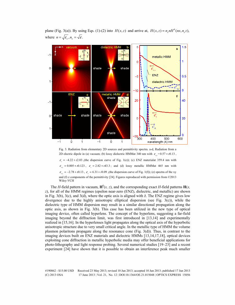
plane (Fig. 3(a)). By using Eqs. (1)-(2) into ( , )H x z and arrive at, 0z z( , ) ( , ),H x z n nH nx n z=
where z z, .n nε ε= =
Fig. 3. Radiation from elementary 2D sources and permittivity spectra. a-d, Radiation from a
2D electric dipole in (a) vacuum; (b) lossy dielectric HMMat 340 nm with x,y
= 0.57 0.13ε ι+ ,
4.22 2.03z
ε ι= − + ,(the dispersion curve of Fig. 1(e)); (c) ENZ materialat 359.4 nm with
x,y0.005 0.123ε ι= + ,
z2.82 43.3ε ι= + ; and (d) lossy metallic HMMat 465 nm with
x,y2.78 0.13ε ι= − + ,
z6.31 0.09iε = + ,(the dispersion curve of Fig. 1(f)); (e) spectra of the xy
and (f) z components of the permittivity [24]. Figures reproduced with permission from ©2013 Wiley-VCH
The H-field pattern in vacuum, H0(x, z), and the corresponding exact H-field patterns H(x, z), for all of the HMM regimes (epsilon near-zero (ENZ), dielectric, and metallic) are shown in Fig. 3(b), 3(c), and 3(d), where the optic axis is aligned with ẑ. The ENZ regime gives low divergence due to the highly anisotropic elliptical dispersion (see Fig. 3(c)), while the dielectric type of HMM dispersion may result in a similar directional propagation along the optic axis, as shown in Fig. 3(b). This case has been utilized in the new type of optical imaging device, often called hyperlens. The concept of the hyperlens, suggesting a far-field imaging beyond the diffraction limit, was first introduced in [13,14] and experimentally realized in [15,16]. In the hyperlenses light propagates along the optical axis of the hyperbolic anisotropic structure due to very small critical angle. In the metallic type of HMM the volume plasmon polaritons propagate along the resonance cone (Fig. 3(d)). Thus, in contrast to the imaging devices built on ENZ materials and dielectric HMMs [13,14,17,18], optical devices exploiting cone diffraction in metallic hyperbolic media may offer beneficial applications for photo-lithography and light response probing. Several numerical studies [19–23] and a recent experiment [24] have shown that it is possible to obtain an interference peak much smaller
#190862 - $15.00 USD Received 23 May 2013; revised 10 Jun 2013; accepted 10 Jun 2013; published 17 Jun 2013(C) 2013 OSA 17 June 2013 | Vol. 21, No. 12 | DOI:10.1364/OE.21.015048 | OPTICS EXPRESS 15056
than the free-space wavelength using both diffracted rays as will be discussed in the next section.
Note that all the discussed types of hyperbolic metamaterials can be realized with the same structure by varying the wavelength of the incident light. Figures 3(e) and 3(f) show permittivity spectra for two components of multilayer structure with optic axis denoted by z. For the multilayer dispersion calculations, the Rytov effective medium theory with nonlocal corrections is employed [5]. According to [25], all structures containing one or more metal-dielectric interfaces can be qualitatively considered as a hyperbolic layer.
Depending on composition and component dimensions, multilayer systems provide hyperbolic dispersion at the UV (Ag/Al2O3) [13], near-IR(Al/ZnO) [26], and mid-IR (InGaAs/AlInAs) [27] frequency ranges. Hyperbolic dispersion has been also demonstrated in nanowire systems [28–30], and homogeneous materials [31–33].
3. Refraction in hyperbolic media
As described above, in hyperbolic media propagation of the energy, given by the Poynting vector, is not collinear to the propagation of the phase fronts, described by the wavevector, which has profound implications for refraction of the waves to and from the hyperbolic structures. Consider first a single plane wave that is incident at an HMM boundary. Electromagnetic field can be described as a linear combination of incident, reflected, and refracted electromagnetic waves. Existence of the continuous planar interface requires conservation of the component of the wavevector parallel to this interface [9], which fixes the directions of the reflected and refracted waves. Application of the boundary conditions results in the amplitudes of these waves.
Consider now the situation when the interface is illuminated not by a single plane wave, but by a rather wide, but finite-sized monochromatic beam. The electromagnetic field of the beam can be represented as a linear combination of the plane waves, and refraction/reflection of each component of the beam can be calculated using the single-wave formalism described above. When the beam is substantially wide, its plane wave decomposition will contain a relatively narrow spectrum of the wavevector components. Consequently, the Poynting vectors of all the refracted components of the beam will be aligned with each other. This common direction of the Poynting flux describes the direction of the propagation of the refracted beam.
Light refraction at the interface with anisotropic crystals is often non-trivial. Even with naturally-occurring materials it is possible to achieve negative refraction for a limited range of angles [34]. When the light is incident from isotropic material onto hyperbolic media, the beam can be refracted in the negative direction [35]. Negative refraction of the beam has been experimentally validated in layered metamaterials at mid-IR [27] and near-IR frequencies [26], in nanowire-based metamaterials at visible frequencies [30], and in homogeneous media at UV frequencies [31].
Negative refraction has been historically considered the hallmark of metamaterials, where it enables planar lenses that are not limited by spherical aberrations [36]. A classic Veselago lens should have an angle- and polarization-independent index of refraction, and thus requires use of an isotropic magnetic media. Nevertheless, hyperbolic materials can mimic the performance of a Veselago lens in waveguide geometry [37]. Practical applications of 3D lenses based on hyperbolic materials are affected by the dependence of their refractive index on the angle [38], which re-introduces image distortion similar to spherical aberration. Such distortions, however, can be limited in ENZ and in canalization imaging [13,14,39].
4. Diffraction in hyperbolic media: sub-wavelength imaging and nanolithography
Any inhomogeneity inside the material or any inhomogeneity along the boundary between two media necessarily leads to diffraction. Qualitatively, the profile of the diffracted beam can be calculated from the Huygens-Fresnel principle. Note that in contrast to conventional
#190862 - $15.00 USD Received 23 May 2013; revised 10 Jun 2013; accepted 10 Jun 2013; published 17 Jun 2013(C) 2013 OSA 17 June 2013 | Vol. 21, No. 12 | DOI:10.1364/OE.21.015048 | OPTICS EXPRESS 15057
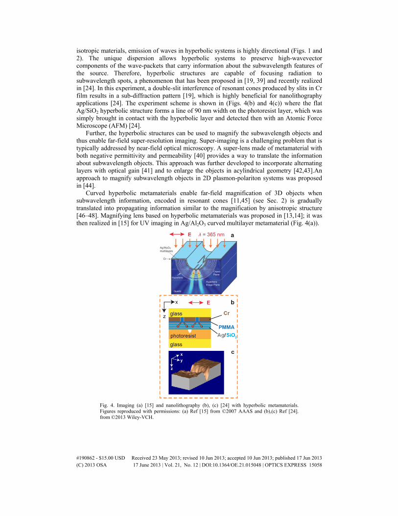
isotropic materials, emission of waves in hyperbolic systems is highly directional (Figs. 1 and 2). The unique dispersion allows hyperbolic systems to preserve high-wavevector components of the wave-packets that carry information about the subwavelength features of the source. Therefore, hyperbolic structures are capable of focusing radiation to subwavelength spots, a phenomenon that has been proposed in [19, 39] and recently realized in [24]. In this experiment, a double-slit interference of resonant cones produced by slits in Cr film results in a sub-diffraction pattern [19], which is highly beneficial for nanolithography applications [24]. The experiment scheme is shown in (Figs. 4(b) and 4(c)) where the flat Ag/SiO2 hyperbolic structure forms a line of 90 nm width on the photoresist layer, which was simply brought in contact with the hyperbolic layer and detected then with an Atomic Force Microscope (AFM) [24].
Further, the hyperbolic structures can be used to magnify the subwavelength objects and thus enable far-field super-resolution imaging. Super-imaging is a challenging problem that is typically addressed by near-field optical microscopy. A super-lens made of metamaterial with both negative permittivity and permeability [40] provides a way to translate the information about subwavelength objects. This approach was further developed to incorporate alternating layers with optical gain [41] and to enlarge the objects in acylindrical geometry [42,43].An approach to magnify subwavelength objects in 2D plasmon-polariton systems was proposed in [44].
Curved hyperbolic metamaterials enable far-field magnification of 3D objects when subwavelength information, encoded in resonant cones [11,45] (see Sec. 2) is gradually translated into propagating information similar to the magnification by anisotropic structure [46–48]. Magnifying lens based on hyperbolic metamaterials was proposed in [13,14]; it was then realized in [15] for UV imaging in Ag/Al2O3 curved multilayer metamaterial (Fig. 4(a)).
Fig. 4. Imaging (a) [15] and nanolithography (b), (c) [24] with hyperbolic metamaterials. Figures reproduced with permissions: (a) Ref [15] from ©2007 AAAS and (b),(c) Ref [24]. from ©2013 Wiley-VCH.
#190862 - $15.00 USD Received 23 May 2013; revised 10 Jun 2013; accepted 10 Jun 2013; published 17 Jun 2013(C) 2013 OSA 17 June 2013 | Vol. 21, No. 12 | DOI:10.1364/OE.21.015048 | OPTICS EXPRESS 15058

5. Photonic density of states and radiative rate engineering
Fermi’s golden rule with Purcell’s effect links the radiative decay rate of spontaneous emission and photonic density of states, which can be modified due to environment in which fluorescent molecules are embedded [49,50]. The most attractive property of the hyperbolic metamaterials pointed in [51] is the broadband and strongly enhanced radiative decay rate for the fluorophore spontaneous emission near or inside a medium relative to free space (Purcell factor). The photonic density of states (PDS) in the metamaterial is related to the volume in k-space enclosed by the corresponding iso-frequency surface [50,51] and may have singularities [51–53]. As we discussed above, the iso-frequencies have closed trajectories (see Fig. 1) which eliminate singularities of the PDS. The value of the enhancement is theoretically limited only by losses [53] or finite period-to-wavelength ratio [53,54]. The finite size of the emitter distribution can limit the HMM density of states even at zero losses [55] and the Purcell factor in hyperbolic metamaterials stays finite due to the discreteness of the actual structure and specific geometry [56–60].
Fig. 5. Wire (a), (b) [28] and layered (c) [25] HMM samples for life time engineering. Figures reproduced with permissions: (a),(b) Ref [28]. from ©2010 OSA and (c) Ref [25]. from ©2012 OSA.
Table 1. Radiative, nonradiative decay rates, apparent quantum yield, and fluorescence and absorption enhancements in layered HMM are shown in the table for four samples,
each at 89 and 21 nm dielectric spacer [25]. Table reproduced with permission from ©2012 OSA.
( )1
r
8s 10
− −Γ ( )1
nr
8s 10κ − −
rr n
κΓ Q Fluorescence Absorption
nm 89 21 89 21 89 21 89 21 89 21 89 21 HMM 1.4 0.54 4.6 5.66 0.3 0.09 0.23 0.09 9.3 1.6 5.4 2.5
Thick Au 0.9 0.18 4.6 4.6 0.2 0.04 0.17 0.04 9.4 0.9 7.9 3.4 Thin Au 0.7 0.15 5.5 6.8 0.13 0.02 0.12 0.02 6.4 0.55 7.7 3.5 Glass, ref 0.62 0.63 3.9 3.96 0.16 0.16 0.14 0.14 1 1 1 3
Experimental studies mainly focus on life time measurements [28,61];this approach does not provide conclusions on the radiative decay and Purcell factor. In a general case, study of both life time and quantum yield is required [25]. Two types of hyperbolic metamaterials, alumina membrane embedded with silver nanowires [28] and multilayer metal-dielectric [25,29],are typically used in optical experiments to prove the theoretically predicted anomalously high photonic density of states in hyperbolic metamaterials. The material in [28] has exhibited a hyperbolic dispersion with the effective values of permittivity (εΠ = 5 + i0.22, ε⊥ = −0.15 + i1.1).In the film deposited onto the silver-filled membrane, the emission life time of dye was as short as: 125 ps (Fig. 5). The shortening of the emission life time is claimed to be due to a large number of available radiative channels, although this was not proved by the measurements. The quantum yield and the lifetime were measured for the multilayer HMM samples in [25] which consisted of 16 stacked layers Au(19nm)/Al2O3(19nm) on a glass substrate, as shown in Fig. 5(c). The quantum yield and life time are related as follows:
#190862 - $15.00 USD Received 23 May 2013; revised 10 Jun 2013; accepted 10 Jun 2013; published 17 Jun 2013(C) 2013 OSA 17 June 2013 | Vol. 21, No. 12 | DOI:10.1364/OE.21.015048 | OPTICS EXPRESS 15059

( ) 1 1r r nrQ , .τ τ κ − −= Γ = Γ + = Γ (7)
Here, rΓ is the radiative decay rate, nrκ is the non-radiative decay rate, τ is the excited
state lifetime, and Γ is the total decay rate. For Ag nanoantennae [62], direct measurements of both the lifetime and the quantum yield changes are necessary for conclusive results of the radiative decay rate and Purcell factor. The quantum yield is simply the ratio of the emitted to the absorbed photons and can be determined by measuring the absorption, emission, reflection, and lifetime of the dye molecules relative to a reference dye film. Then the results are compared with the radiative decay rate of control samples that are similar to those used in classic experiments, namely thin and thick gold films. By using the reference method, the quantum yield can be experimentally obtained through absorption and fluorescence measurements for the samples under study relative to the corresponding dye/epoxy reference sample [25]. Purcell factors are shown in Table 1. Our maximum changes in the radiative decay rates relative to Rh800 in methanol are about 1.2 for dye molecules on glass, 1.35 for thin gold films, 1.73 for thick gold, and 2.7 for multilayer HMM samples.
The photonic density of states (PDS) in emitters can be modified due to the interference of emitted and reflected waves near metal films [63,64], which have led to the development of PDS engineering that uses metal-dielectric interfaces [64,65], metal-film interfaces [66–68]. Non-radiative decay can be modified due to dipole-image interaction and excitation of the surface-plasmon polaritons or wave-guiding modes. Indeed, similar to SPP, the limiting factor of the radiative decay is in the out-coupling of the HMM modes to the low PDS of free space [69]. Thus the ratio between leaky and bound modes [66] should be a critical parameter in theory, which would allow to determine effect of HMM on both, the radiative and nonradiative rates. This is the main limitation of the existing theories.
6. Beyond the effective medium theory: nonlocality corrections and additional waves
Hyperbolic metamaterials provide unprecedented opportunities for controlling the flow of optical information. However, the majority of exciting applications of hyperbolic systems can be traced to extreme (either vanishingly small, or infinitely big) values of the components of the effective permittivity tensor or to extreme values of effective refractive index eff z .n k c ω= To name a few, traditional implementations of hyperlens and canalization
imaging systems rely on e o .ε ε Modulation of photonic density of states, as well as
numerous designs leading to subwavelength focusing [19,70] rely on the existence of propagating modes at eff 1.n In fact, “extreme” photonics is deeply interweaved with the
novel applications of metamaterials, and this relationship extends far beyond the area of hyperbolic systems to cloaking and light transmission through subwavelength channels [71–73] and other applications.
#190862 - $15.00 USD Received 23 May 2013; revised 10 Jun 2013; accepted 10 Jun 2013; published 17 Jun 2013(C) 2013 OSA 17 June 2013 | Vol. 21, No. 12 | DOI:10.1364/OE.21.015048 | OPTICS EXPRESS 15060

Fig. 6. Effect of nonlocality on extinction in nanowire medium: at high absorption (a) metamaterial exhibits the extinction spectrum consistent with predictions of effective medium theory, at smaller losses (b), interference of two TM-polarized beams becomes evident in transmission [29]. Figures reproduced with permission from ©2009 APS.
However, the very composites that bring to life the extreme behaviors usually provide tight limitations on what can be realized in realistic systems. The optics of nanolayered composites can be understood analytically, with the help of transfer matrix formalism [5,74].
The effective parameters for a multilayer, periodic structure with a period d b a= + and containing both a metal (with permittivity mε and permeability mμ ) and a
dielectric ( )dd ,ε μ are given by [5]:
d m m d m do o o
o o
1 , ,4
b akab
d a b
μ ε μ ε ε ειε ε εε μ
− + = − = + (8)
d m m d m do o o
o o
1 , ,4
b akab
d a b
μ ε μ ε μ μιμ μ με μ
− + = + = + (9)
1 d me e e .,
a b
a b
ε εε ε ε − += =
+ (10)
It was shown in [54,56] that increasing the number of layers at the same thickness brings the results for the multilayer structure closer and closer to those of a homogeneous sample. Note that Eqs. (8)-(10) were obtained in [5] for infinite periodic system with elementary cell made of two layers. For bounded layered systems the key moment of the problems is the boundary conditions. Modification of the boundary conditions by introduction of additional surface currents suggested in [75] returns the conventional permittivity and permeability of metamaterials their usual physical properties. The modified retrieval procedure based on reflection/transmission yields bulk values of effective impedance and refractive index, which are independent of system size and boundary realization, whereas the conductivities of the excess surface currents depend on the property of the interface [75].
Note that the corrections to ideal effective medium theory (EMT) response can be described in terms of a permittivity tensor with wavevector-dependent components. Since wavevector dependence of permittivity can be related to long-range correlation in polarization [76,77], materials that exhibit such dependence are known as nonlocal media. The true response of any composite structure is nonlocal. The significance of nonlocal corrections, however, depends on the particular application and on geometry under consideration.
Optics of nanowire metamaterials offer unique opportunity to realize regimes where nonlocality not corrects, but rather dominates the response of the system. Nanowire materials
#190862 - $15.00 USD Received 23 May 2013; revised 10 Jun 2013; accepted 10 Jun 2013; published 17 Jun 2013(C) 2013 OSA 17 June 2013 | Vol. 21, No. 12 | DOI:10.1364/OE.21.015048 | OPTICS EXPRESS 15061

are known to provide a flexible platform that can realize elliptic, hyperbolic, and -near-zero (ENZ) regimes in the same material. In the ENZ regime, the optical properties of the [meta]material can be approximated as ( )e , ( )ε ω ιε δ′′= +k k , with ε ′′ representing material
absorption at ENZ frequency and ( )δ k describing nonlocal correction to the EMT response
[77].Therefore, when the losses in material are substantially small, the nonlocal “correction” dominates the polarization inside the system.
Direct solutions of Maxwell equations demonstrate that in this case, [meta-]material supports not two, but at least three different waves, at least two of which have identical (TM) polarization. The existence of additional waves fundamentally changes optical response of the system.
Thus, the spectrum of extinction in nonlocal ENZ metamaterials is dominated not by absorption-related angle-dependent maximum, but rather by collection of angle- and wavelength-dependent maxima corresponding to the points of destructive interference of two TM-polarized beams (Fig. 6). Such changes in optical response of nonlocal metamaterials were first observed in [29].
Any phenomenon that relies on optical response to change of material parameters can potentially be greatly enhanced. In particular, the interference-based transmission has already provided a new way to enhance nonlinear optical response employing nonlocal metamaterials. A clear manifestation of such an enhancement was reported in [78], where optical nonlocality provides a four-fold enhancement to optical nonlinearity in TM-polarized response in comparison to local TE-polarized response of the same metamaterial.
Strong optical nonlocality and existence of additional waves in ENZ regime in layered structures was reported in [79,80], and many other designs of ENZ metamaterials are likely to follow this trend. Optical nonlocality remains an active research area with multiple groups working on better understanding of the collective excitations that underline ENZ response of macroscopic materials
7. Natural hyperbolic materials
The vital aspects in designing an optical element with hyperbolic dispersion is either developing a metamaterial or selecting a natural dispersive material with strong anisotropy. This alternative approach to hyperbolic media has been recently demonstrated as a simulated example of negative refraction in graphite (see Fig. 7(a)) [31]. For far-infrared and THz domains naturally occurring hyperbolic materials have been discussed for a waveguide application at about 20 μm, 58 μm, and 255 μm using, respectively, sapphire, bismuth, or triglycine sulfate [32].
#190862 - $15.00 USD Received 23 May 2013; revised 10 Jun 2013; accepted 10 Jun 2013; published 17 Jun 2013(C) 2013 OSA 17 June 2013 | Vol. 21, No. 12 | DOI:10.1364/OE.21.015048 | OPTICS EXPRESS 15062

Fig. 7. Natural hyperbolic media. a, Negative refraction in graphite [31]; b, c, Components of the principal dielectric tensor of calcite (b) [81] and monocrystalline Bismuth (c) [32]. Figure 7(a) reproduced with permission from Appl. Phys. Lett. 98, 101901 (2011) Copyright 2011 American Institute of Physics.
A similar example has been demonstrated [81] with one of the most common mineral, calcite (CaCO3), which, on top of its text-book famous birefringence, exhibits two very distinct non-overlapping ordinary and extraordinary absorption bands in the mid-infrared spectral range as a result of the internal vibration modes of its planar carbonate ions. Two sets of optical dispersion parameters, ordinary and extraordinary, using just a few terms of the Lorentz oscillator model, have been fit to the experimental data using generalized ellipsometry [82].
Dispersion spectra of ɛo and ɛe depicted in Fig. 7(b), indicate that the best figure of merit
( )Re( ) / Im( ), {o,e}j j jFOM jε ε= − = is around 4.7 at 6.75 µm, and around 6.3 at 11.33 µm
for the ordinary and extraordinary components respectively
#190862 - $15.00 USD Received 23 May 2013; revised 10 Jun 2013; accepted 10 Jun 2013; published 17 Jun 2013(C) 2013 OSA 17 June 2013 | Vol. 21, No. 12 | DOI:10.1364/OE.21.015048 | OPTICS EXPRESS 15063

o e( 6.75 ) 2.59 0.55, ( 11.33 ) 1.90 0.30.m mε λ μ ι ε λ μ ι= = − + = = − + The major absorption
peaks for the ordinary and extraordinary rays are correspondingly located at 7.13 mλ μ= and
11.48 mμ . Strong hyperbolic anisotropy is not limited to resonance phonon excitations that
occur for example in calcite. For example in Bi, a Group V semimetal with rhombohedral lattice and trigonal symmetry, such anisotropy is induced by a substantial difference in its electron effective masses along different directions in the crystal. Hence, the most interesting feature of the Bi dispersion - transition from Re( ) 0jε > to { }Re( ) 0, o, ej jε < = , _ is
determined by the strong anisotropy of its plasma frequency within a band between 53.7 mλ μ= and 63.2 mμ as shown in Fig. 7(c). The existence of that 10-μm band has been
confirmed experimentally in [33]. In conclusion, while important fundamentals of understanding of optics of hyperbolic
media have been laid in the middle of previous century, this unique research area continued explosive growth during the past decade, allowing to advancements beyond the traditional material and functional choices for all components of the optical part of electromagnetic spectrum. These materials lay the foundations for numerous applications with unparalleled performance in lithography, imaging, sensing, and quantum photonics. Effects and devices based on hyperbolic dispersion provide numerous exciting opportunities for future research at the convergence of material science, physics, engineering, and numerical modeling.
Acknowledgments
VPD and AVK acknowledge the support from AFRL Materials and Manufacturing Directorate - Applied Metamaterials Program. VP acknowledges the support from NSF (grant ## ECCS-1102183, DMR-1209761) and ARO (grant # W911NF-12-1-0533)
#190862 - $15.00 USD Received 23 May 2013; revised 10 Jun 2013; accepted 10 Jun 2013; published 17 Jun 2013(C) 2013 OSA 17 June 2013 | Vol. 21, No. 12 | DOI:10.1364/OE.21.015048 | OPTICS EXPRESS 15064