i image resizing using thin-plate spline behrad...
TRANSCRIPT

i
IMAGE RESIZING USING THIN-PLATE SPLINE
BEHRAD SAEEDINEJAD
A project report submitted in partial fulfilment of the
requirements for the award of the degree of
Master of Engineering (Electrical - Electronics & Telecommunications)
Faculty of Electrical Engineering
Universiti Teknologi Malaysia
JUNE 2014

iii
To my beloved father and mother
for their endless support and encouragement.

iv
ACKNOWLEDGEMENTS
I wish to express my sincere appreciation to my Supervisor
Associate Professor Dr. Syed Abdul Rahman for giving me an opportunity to do this
project and for his patience, motivation, enthusiasm and immense knowledge through
this time.
And I would like to thank my parents whom without them I don’t have any
motivation to continue my life, for offering their full support and encouragement.

v
ABSTRACT
Interpolation of scattered data refers to the problem of passing a smooth
surface through a non-uniform distribution of data samples. In many science and
engineering fields, where data are often generated or measured at few and irregular
positions, this problem is of practical importance. Over the past decades, different
methods have been used to yield solutions to the multi-variate scattered data
interpolation problem. One of the popular methods that is commonly used is Thin-
Plate Spline (TPS). A thin-plate spline is a physically inspired two-dimensional
interpolation structure for randomly spaced tabulated data(𝑥𝑖 , 𝑦𝑖, 𝑓(𝑥𝑖, 𝑦𝑖)). TPS is
the generalization of the natural cubic spline in one dimension. The spline surface
represents a thin sheet of metal that is limited not to move at the grid points. Such
surfaces are preferred for various modeling and design applications. For decades,
TPS had been used in mechanics and engineering, and they were initiated to image
analysis community by Bookstein. TPS is practically one of the most frequently
used transformation function in non-rigid image registration. In this project, TPS
is used for the image resizing purpose and its result shows around 12%
improvement in terms of quality compared with Bicubic interpolation method.
Furthermore, an approach is proposed to reduce the computational cost drastically
for large scale images. The results show that this method speeds up the evaluation
of TPS interpolation function up to 16 times, compared with direct evaluation. This
approach involves windowing the image in order to implement TPS on smaller data
sets rather than applying it to the whole image at once.
vi
ABSTRAK
Interpolasi bagi data tidak tersusun merujuk kepada permasalahan yang
terjadi apabila melalui permukaan yang sekata pada titik-titik data yang tidak
seragam. Di dalam bidang sains dan kejuruteraan, data-data yang diperoleh
selalunya sedikit atau pada kedudukan janggal dan merupakan permasalahan
praktik. Kebelakangan ini, pelbagai cara telah digunakan untuk mendapatkan
penyelesaian pada permasalahan interpolasi data tidak seragam. Salah satu
penyelesaian yang masyhur ialah menggunakan Splin Plat-Nipis(TPS). Splin Plat-
Nipis secara fizikal telah di inspirasi kan daripada struktur interpolasi dua dimensi
untuk data rawak (𝑥𝑖, 𝑦𝑖 , 𝑓(𝑥𝑖, 𝑦𝑖)). TPS terbina daripada splin kiub asli dalam satu
dimensi. Permukaan splin adalah satu lapisan metal yang nipis dan pergerakannya
terbatas pada satu-satu titik grid. Permukaan sebegini menjadi pilihan untuk model
pelbagai dan juga aplikasi rekaan. Sebelum ini, TPS digunakan dalam bidang
mekanik dan kejuruteraan dan Bookstein memulakan pengunaakn TPS dalam
konteks analisis imej. TPS juga merupakan kaedah lazim yang selalu digunakan
untuk fungsi transformasi pada pendafttaran imej tidak tetap. Dalam projek ini,
TPS digunakan pada imej untuk tujuan pensaizan semula dan keputusan yang
diperoleh menunjukkan peningkatan kualiti sebanyak 12% berbanding dengan
kaedah konvensional. Tambahan pula, kaedah ini dicadangkan untuk
mengurangkan kadar kerumitan pada imej berskala besar secara mendadak. Kaedah
ini meningkatkan tahap kelajuan sehingga 16 kali untuk penilaian interpolasi
menggunakan kaedah TPS berbanding penilaian terus. Kaedah ini melibatkan cara
membahagikan imej kepada tetingkap-tetingkap lebih kecil untuk perlaksanaan
TPS pada set data yg lebih kecil berbanding kepada keseluruhan imej sekaligus.

vii
TABLE OF CONTENT
CHAPTER TITLE PAGE
DECLARATION ii
DEDICATION iii
ACKNOWLEDGEMENT iv
ABSTRACT v
ABSTRAK vi
TABLE OF CONTENTS vii
LIST OF TABLES ix
LIST OF FIGURES x
LIST OF ABBREVIATIONS xii
1 INTRODUCTION 1
1.1 Introduction 1
1.2 Background 1
1.3 Problem Statement 2
1.4 Objective of the study 3
1.5 Scope of the study 4
2 LITERATURE REVIEW 5
2.1 Basic interpolation methods 5
2.2 Basic interpolation methods progression 8
2.3 Non-interpolation based approaches 10
2.4 Introduction to spline interpolation 12
2.5 Thin-plate spline interpolation theory 13
2.6 Thin-plate spline applications 19

viii
3 METHODOLOGY 22
3.1 Image resizing using TPS 22
3.1.1 TPS block 23
3.1.2 Location finder block 27
3.1.3 Mapping block 28
3.2 Windowing method 29
3.3 Analysis plan 31
3.3.1 SSIM 32
4 EXPERIMENTAL RESULT 34
4.1 Image resizing using TPS (direct
evaluation)
35
4.1.1 Quality aspect 35
4.1.2 Execution time aspect 40
4.2 Image resizing using TPS (Windowing
41 method)
4.2.1 Quality aspect 41
4.2.2 Execution time aspect 44
5 CONCLUSION AND FUTURE WORK
46 RECOMMENDATION
5.1 Conclusion 46
5.2 Future work recommendation 47
REFERENCES 48

ix
LIST OF TABLES
TABLE NO. TITLE PAGE
4.1 SSIM for all sample images, resized using different
methods and sharpened with different rates
39
4.2 Execution time of resizing all sample images using
different methods
41

x
LIST OF FIGURES
FIGURE NO. TITLE PAGE
1.1 Image resizing 2
1.2 Undesirable artifacts a) Edge halos b) Blurred
c) Aliased
3
2.1 Nearest neighbor interpolation kernel 6
2.2 Bilinear interpolation kernel 7
2.3 Bilinear interpolation kernel 7
2.4 Artifacts triangle 1) Nearest neighbor 2) Bilinear
3) Bicubic
8
2.5 The result of one row interpolation using A-
Bilinear
9
2.6 The example of Least Directional Differences
method for an unknown pixel X
9
2.7 Lagrange interpolation result compared with
expected result
12
2.8 Cubic spline result for the same data points 13
3.1 Functional block diagram of image resizing
using TPS
23
3.2 Sweep pattern and pixels labeling 25
3.3 G matrix for an 64 × 64 image 27
3.4 New pixels locations 28
3.5 Mapping new pixels to new matrix with desired
size
29
3.6 Some independent pixels in an image 30
3.7 Windowing method procedure (a-d) 31
xi
4.1 Sample images used in this experiment a) MR
b) AQUA c) CAR d) CAT e) HOUSE
34
4.2 MR image, resized using a) Bilinear b) Bicubic
c) TPS
35
4.3 MR image, resized using a) Bilinear b) Bicubic
c) TPS and cropped to the center
36
4.4 MR image, resized using a) Bilinear b) Bicubic
c) TPS, sharpened 25 times and cropped to the
center
37
4.5 HOUSE image, resized using a) Bilinear
b) Bicubic c) TPS, sharpened 25 times and
cropped to the center
38
4.6 SSIM VS. Sharpness rate for a) CAT image
b) HOUSE image
40
4.7 MR image resized using TPS a) Direct
evaluation b) Windowing method
42
4.8 Error images for MR image when window size
for windowing method is 𝟏𝟎 × 𝟏𝟎 with a) 2
pixels overlap b) 4 pixels overlap c) 5pixels
overlap
43
4.9 SSIM VS. Window size graph for different
number of pixels overlap for MR image
44
4.10 Execution time VS. Window size graph for
different number of pixels overlap for MR image
45
4.11 a) Execution time and b) SSIM graphs versus
window size for House image
45

xii
LIST OF ABBREVIATIONS
2D - Two-Dimensional
3D - Three-Dimensional
A-Bilinear - Advanced Bilinear
CIM - Curvature Interpolation Method
DAP - Difference of Adjacent Pixels
dB - decibel
DFT - Discrete Fourier Transform
FFT - Fast Fourier Transform
IEEE - Institute of Electrical and Electronics Engineers
LMS - least mean square
MATLAB - Matrix Laboratory
MSE - Mean Squared Error
PDE - Partial Differential Equation
PSNR - Peak Signal to Noise Ratio
RLS - Recursive Least Square
TPS - Thin-Plate Spline

1
CHAPTER 1
INTRODUCTION
1.1 Introduction
Due to the development of modern information technology, image processing
is becoming more and more important in our life. Digital image processing has
demonstrated an extraordinary evolution in the past decades, in terms of both
applications and theoretical development. It is practically a leading technology in
several vital areas, such as Internet-based services, digital telecommunications,
broadcasting, multimedia systems and medical imaging. Among all the technologies
that digital image processing provides, image resizing is a remarkably important
technology, due to its wide applications in different fields such as, scientific imaging,
graphic design, multimedia communication, medical imaging, police security, etc. In
order to have better and fine images for users, images are regularly required to be
resized or reproduced to different resolutions.
1.2 Background
Technically, resizing whether implies enlargement of an image for a better
view of it, or implies image reduction to reproduce the smaller size of it for
applications that size and speed are the main concern. Image resizing is referred to
inserting new pixels into the image in order to expand the size or removing pixels to
reduce the size.
2
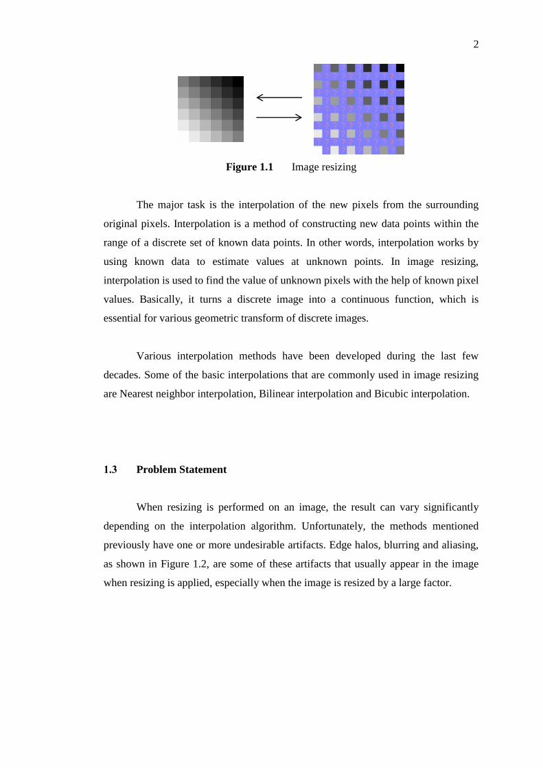
Figure 1.1 Image resizing
The major task is the interpolation of the new pixels from the surrounding
original pixels. Interpolation is a method of constructing new data points within the
range of a discrete set of known data points. In other words, interpolation works by
using known data to estimate values at unknown points. In image resizing,
interpolation is used to find the value of unknown pixels with the help of known pixel
values. Basically, it turns a discrete image into a continuous function, which is
essential for various geometric transform of discrete images.
Various interpolation methods have been developed during the last few
decades. Some of the basic interpolations that are commonly used in image resizing
are Nearest neighbor interpolation, Bilinear interpolation and Bicubic interpolation.
1.3 Problem Statement
When resizing is performed on an image, the result can vary significantly
depending on the interpolation algorithm. Unfortunately, the methods mentioned
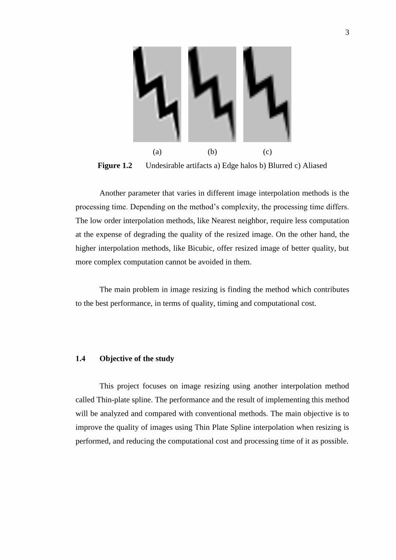
previously have one or more undesirable artifacts. Edge halos, blurring and aliasing,
as shown in Figure 1.2, are some of these artifacts that usually appear in the image
when resizing is applied, especially when the image is resized by a large factor.
3
(a)
(b)
(c)
Figure 1.2 Undesirable artifacts a) Edge halos b) Blurred c) Aliased
Another parameter that varies in different image interpolation methods is the
processing time. Depending on the method’s complexity, the processing time differs.
The low order interpolation methods, like Nearest neighbor, require less computation
at the expense of degrading the quality of the resized image. On the other hand, the
higher interpolation methods, like Bicubic, offer resized image of better quality, but
more complex computation cannot be avoided in them.
The main problem in image resizing is finding the method which contributes
to the best performance, in terms of quality, timing and computational cost.
1.4 Objective of the study
This project focuses on image resizing using another interpolation method
called Thin-plate spline. The performance and the result of implementing this method
will be analyzed and compared with conventional methods. The main objective is to
improve the quality of images using Thin Plate Spline interpolation when resizing is
performed, and reducing the computational cost and processing time of it as possible.

4
1.5 Scope of the study
The scope of study is listed as below:
This project focuses only on still images rather than videos.
This project uses grayscale images for the experimental result.
Thin-plate spline interpolation will be studied and implemented on
different sample images using MATLAB software.

48
REFERENCES
1. Maeland, E., On comparison of Interpolation Methods. IEEE Transaction on
Medical Imaging, 1988. 7(3).
2. Parker, J.A., R.V. Kenyon, and D. Troxel, Comparison of interpolating
methods for image resampling. Medical Imaging, IEEE Transactions on, 1983.
2(1): p. 31-39.
3. Rafael C. Gonzalez and Richard E. Woods, Digital Image Processing. 2nd
Edition ed. 2002: Prentice Hall.
4. Wang, J., Z. Li, and M. Zhang. Two New Proposed Image Zooming Methods.
in Wireless Communications Networking and Mobile Computing (WiCOM),
2010 6th International Conference on. 2010.
5. Kim, H., et al. Advanced bilinear image interpolation based on edge features.
in 2009 First International Conference on Advances in Multimedia. 2009.
6. Mehdi Hajizadeh, M.S.H., Ashkan Tashk, Improvement of Image Zooming
Using Least Directional Differences based on Linear and Cubic Interpolation.
IEEE Transaction, 2009.
7. Xu, X., et al., Image Interpolation Based on the Wavelet and Fractal.
International Journal of Information Technology, 2001. 7(2).
8. Zhiwei, W., et al. Image zooming by improved interpolation scheme using FFT.
in Circuits and Systems, 1993., Proceedings of the 36th Midwest Symposium
on. 1993.
9. Plaziac, N., Image interpolation using neural networks. IEEE transactions on
image processing: a publication of the IEEE Signal Processing Society, 1998.
8(11): p. 1647-1651.
10. Belahmidi, A. and F. Guichard. A partial differential equation approach to
image zoom. in Image Processing, 2004. ICIP '04. 2004 International
Conference on. 2004.

49
11. Kim, H., Y. Cha, and S. Kim, Curvature interpolation method for image
zooming. Image Processing, IEEE Transactions on, 2011. 20(7): p. 1895-1903.
12. Faghih, M. and H. Pourghassem. A novel interpolation method using radon
transform. in Signal Processing and its Applications (CSPA), 2011 IEEE 7th
International Colloquium on. 2011.
13. Hou, H.S. and H. Andrews, Cubic splines for image interpolation and digital
filtering. Acoustics, Speech and Signal Processing, IEEE Transactions on,
1978. 26(6): p. 508-517.
14. Richard, L. and J. Burden, Douglas Faires. Numerical analysis, 2002: p. 186-
226,772.
15. Harder, R.L. and R.N. Desmarais, Interpolation using surface splines. Journal
of Aircraft, 1972. 9(2): p. 189-191.
16. Duchon, J., Interpolation des fonctions de deux variables suivant le principe
de la flexion des plaques minces. ESAIM: Mathematical Modelling and
Numerical Analysis-Modélisation Mathématique et Analyse Numérique, 1976.
10(R3): p. 5-12.
17. Meinguet, J., Multivariate interpolation at arbitrary points made simple.
Zeitschrift für angewandte Mathematik und Physik ZAMP, 1979. 30(2): p.
292-304.
18. Wahba, G. and J. Wendelberger, Some new mathematical methods for
variational objective analysis using splines and cross-validation. 1979:
Defense Technical Information Center.
19. Wahba, G., How to smooth curves and surfaces with splines and cross-
validation. 1979, WISCONSIN UNIV-MADISON DEPT OF STATISTICS.
20. Wahba, G., Spline bases, regularization, and generalized cross-validation for
solving approximation problems with large quantities of noisy data.
Approximation theory III, 1980. 2.
21. Wahba, G., Bayesian" confidence intervals" for the cross-validated smoothing
spline. Journal of the Royal Statistical Society. Series B (Methodological),
1983: p. 133-150.
22. Ghosh, A. and D.D.S. Kindermann, Efficient Thin Plate Spline Interpolation
and its Application to Adaptive Optics. 2010, Institut für Industriemathematik,
Germany.

50
23. Bookstein, F.L., Principal warps: Thin-plate splines and the decomposition of
deformations. IEEE Transactions on pattern analysis and machine intelligence,
1989. 11(6): p. 567-585.
24. Goshtasby, A.A., 2-D and 3-D image registration: for medical, remote
sensing, and industrial applications. 2005: John Wiley & Sons.
25. Zitova, B. and J. Flusser, Image registration methods: a survey. Image and
vision computing, 2003. 21(11): p. 977-1000.
26. Lapeer, R. and R. Prager, 3D shape recovery of a newborn skull using thin-
plate splines. Computerized Medical Imaging and Graphics, 2000. 24(3): p.
193-204.
27. Guo, H., J. Jiang, and L. Zhang, Building a 3D morphable face model by using
thin plate splines for face reconstruction, in Advances in Biometric Person
Authentication. 2005, Springer. p. 258-267.
28. Sinthanayothin, C. and W. Bholsithi. 3D facial deformable using cubic spline
and Thin Plate Spline. in Electrical Engineering/Electronics, Computer,
Telecommunications and Information Technology, 2009. ECTI-CON 2009. 6th
International Conference on. 2009. IEEE.
29. Zhang, Y., et al., Fake finger detection based on thin-plate spline distortion
model, in Advances in Biometrics. 2007, Springer. p. 742-749.
30. Lombaert, H. and F. Cheriet. Geodesic Thin Plate Splines for Image
Segmentation. in Pattern Recognition (ICPR), 2010 20th International
Conference on. 2010. IEEE.
31. Nejati, M., R. Amirfattahi, and S. Sadri. A fast hybrid approach for
approximating a thin-plate spline surface. in Electrical Engineering (ICEE),
2010 18th Iranian Conference on. 2010. IEEE.
32. Wang, Z., et al., Image quality assessment: from error visibility to structural
similarity. Image Processing, IEEE Transactions on, 2004. 13(4): p. 600-612.