i- o · software products. ibm is a registered ... which appear on thc~ serial number label and...
TRANSCRIPT

I-o ... o
o Compumotor Division Parker Hannifln Corporation pin 88-013439-01 A Parker

Options Manual for the
4400 Series Machine Controller
Versbn 1.0

Contents
1 Introduction .............................................................. 1 1.1 Description of Options . . . . . . . . . . . . . . . . . . . . . . . . . . . . . . . . . . . . . . . . . . . . . . . . .. 1
1.1.1 The 4400-HYP Model of the 4400 Series Machine Controller ............... 1 1.1.2 Cam Controller Option ............................................. 2 1.1.3 Network Communication Option ..................................... 2 1.1.4 Resource Server™ Option .......................................... 3 1.1.5 Flying Position Measurement Option .................................. 3 1.1.6 Non-volatile Memory Options ....................................... 4 1.1.7 Random Access Memory Options .................................... 4 1.1.8 Color Panelmaker® Application Development System ..................... 4
2. Cam Controller Option ...................................................... 7
3. Network Communication Option ............................................. 51
4. Resource Server™ Option .................................................. 93
© 1992, Compumotor Division, Parker Hannifin Corporation Panelmaker is a registered trademark, and Resource Server and Parasol-II are trademarks for proprietary software products. IBM is a registered trademark of International Business Machines Corporation.
4400-0P1NMAN-792
- i-
Introduction
1. Introduction
The 4400 Series Machine Controller may be enhanced with optional features and capabilities. This manual contains instructions for identifying and using the options installed on your 4400 controller. This may contain instructions for options which are not installed on your 4400. In addition, some options do not require additional documentation.
The following options are documented in this manual: • Cam Controller Option • Network Communication Option • Resource Server Option
The following options are documented elsewhere: • The Panelmaker Development System is covered in the Panelmaker User's Guide and the
Addendumfor Color Panelmaker Version 1.4. • The use of non-volatile memory is covered in Section 5 of the 4400 Series Machine
Controller User's Guide. • See the documentation for the Onswit command in the Addendum for the 4400 Series
Machine Controller Version 4.4 for guidance in using the Flying Position Measurement Option.
The Random Access Memory options do not require documentation.
The following section describes how to determine which options are installed in your 4400 controller and which sections of this manual are applicable to the options installed on your controller.
1.1 Description of Options
The benefits, option code, applicable documentation, and required accessories for each option are described below. The option codes, which appear on thc~ serial number label and login message, identify the options that are installed on the 4400 controller.
1.1.1 The 4400-HYP Model of the 4400 Series Machine Controller
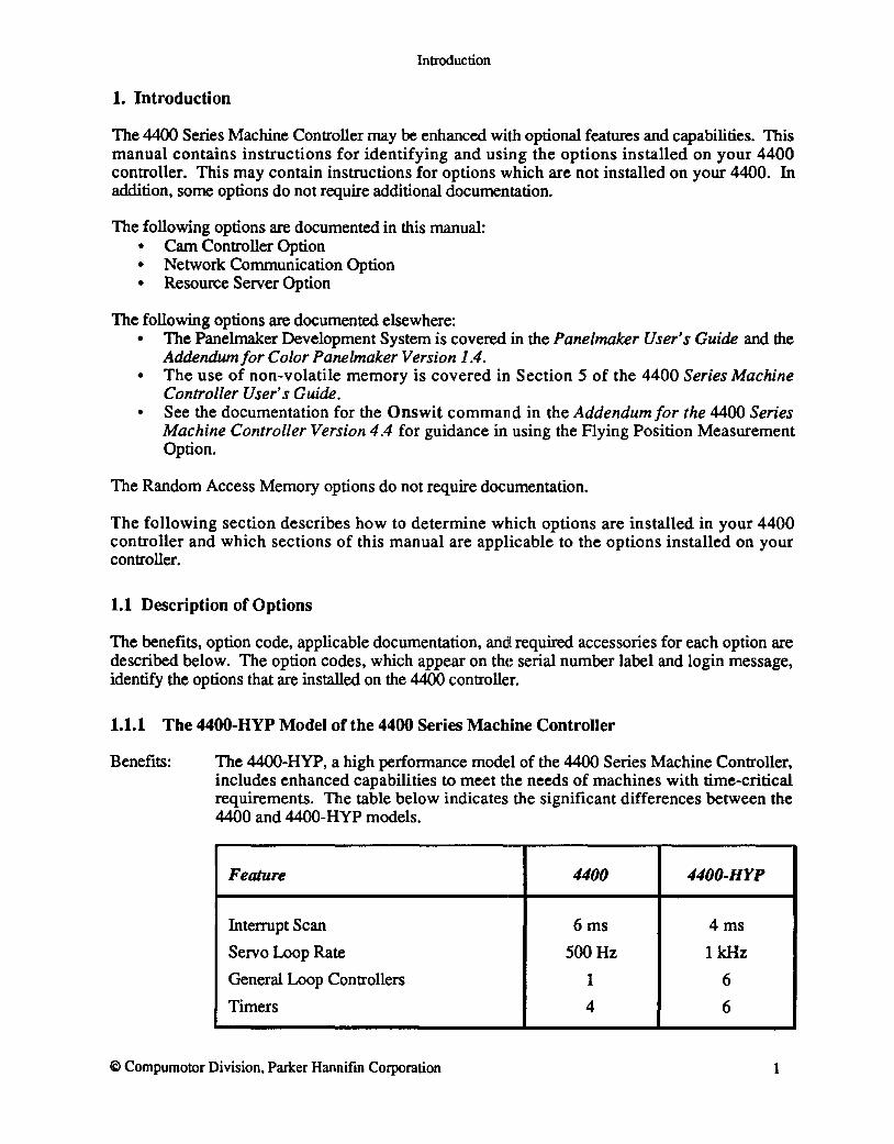
Benefits: The 44OO-HYP, a high performance model of the 4400 Series Machine Controller, includes enhanced capabilities to meet the needs of machines with time-critical requirements. The table below indicates the significant differences between the 4400 and 4400-HYP models.
Feature 4400 4400-HYP
Interrupt Scan 6ms 4ms
Servo Loop Rate 500Hz 1kHz
General Loop Controllers 1 6
Timers 4 6
© Compumotor Division. Parker Hannifin Corporation 1
Introduction
Product Numbers: 4404-HYP or 4408-HYP
Option Codes: Not applicable
Documentation: No special documentation required.
Accessories: Varies with configuration and intended use.
1.1.2 Cam Controller Option Benefits: The Cam Controller option provides all electronic replacement for mechanical
cams by providing tightly coordinated cam motion through position-based, table-specified linking of a master axis and a slave axis. A table of the corresponding slave and master axis positions is created to describe the desired motion. The position of the slave axis :relative to the position of the master axis detennines the resulting cam motion.
Product Number: 4400-CAM
Option Code: - CP
Documentation: Documentation for the Cam Controller option is found in the second section of this manual.
Accessories: None required.
1.1.3 Network Communication Option
Benefits: The Network Communication option is used to interconnect multiple 4400 controllers in a network. The network allows you to easily send commands, share axis data, I/O information, and application specific data between multiple 4400 controllers - without requiring you to design, implement, and test a communications protocol. Command execution and error handling between multiple controllers is accommodated. The Network option (4400-NET) is composed of the Parallel Interface Option (4400-PI) and the Enhanced Communication option (4400-EC). The Parallel Interface option is used for the development environment and the Enhanced Communication option is used for run-time network communications between 4400 controllers. All controllers on the network are required to have this option.
Product Number: 4400-NET
Option Codes: - EC (for the Enhanced Communication option) and - PI (for the Parallel Interface option)
Documentation: Documentation for the Network Communication option is found in the third section of this manual, which is entitled Enhanced Communication/or the 4400 Series Machine Controller.
2 © Compumotor Division, Parker Hannifin Corporation
Accessories:
Introduction
A Network Serial Cable: 4400-CAS-2NET for connecting 2 controllers 44OO-CAS-4NET for connecting up to 4 controllers 4400-CAS-7NET for connecting up to 7 controllers
Network Development Kit: The kit includes the 44OO/PC High Speed Parallel Communication Card (44oo-COM-P) for the IBM-PC or compatible and the appropriate Network Interface Cable.
NET-DK-2 for connecting 2 controllers NET-DK-4 for connecting up to 4 Icontrollers NET -DK-7 for connecting up to 7 Icon trollers
1.1.4 Resource Server Option
Benefits: The Resource Server option provides simple access to disk files and devices controlled by an external computer. Access to disk files can be used to provide mass storage for part programs, SPC data, exception logging, off-line part programming, and other mass storage requirements. In addition, the Resource Server option connects the 4400 to the computer bus and allows it to directly access the devices that are connectc=d to the computer bus (e.g., bar code readers, vision systems, network interfaces, etc.)
Product Number: 4400-RS
Option Code: - RS
Documentation: Documentation for the Resource Server option is found in fourth section of this manual.
Accessories: 4400 Serial Communications Cable (44oo-CAS-9 or 44OO-CAS-2S).
1.1.5 Flying Position Measurement Option
Benefits: The Flying Position Measurement option allows the 4400 to latch the position of any axis within ± 1 encoder count using the Onswit command and dedicated I/O.
Product Number: 44OO-FPM-4 for 4-axis models 44OO-FPM-8 for 8-axis models
Option Code: - FP
Documentation: See documentation for the Onswit command in the Addendum for 4400 Series Machine Controller Version 4.4. Flying Position Measurement is automatically invoked if switch functions 2 or 7 are selected.
Accessories: None required.
1.1.6 Non-volatile Memory Options
© Compumotor Division, Parker Hannifin Corporation 3
Benefits:
Inttoduction
The Non-volatile Memory options allow the non-volatile memory of the 4400 controller to be expanded. Additional non-volatile memory allows the 4400 to store application programs and part data files, which allows the 4400 to operate stand alone - without a host. The Non-volatile Memory option is available in 256,512, and 1024 kilobyte sizes.
Product Numbers: 4400-NV256, 4400-NV512, and 44OO-NVI024
Option Codes: - N2, - N5, and - NI0, respectively
Documentation: The use of non-volatile memory is covered in Section 5 of the 4400 Series Machine Controller User's Guide.
Accessories: None required
1.1.7 Random Access Memory (RAM) Options
Benefits: The RAM options allow the random access memory of the 4400 to be expanded beyond the 400 kilobytes that is installed as standard. Additional RAM allows the 4400 to store large application programs and data files. The RAM options are available in 600 kilobyte and 1 and 2 megabyte sizes.
Product Numbers: 4400-M600, 4400-Ml000, and 4400-M2000
Option Codes: - M6, - MI0, and - M20, respectively
Documentation: None required
Accessories: None required
1.1.8 Color Panel maker Application Development System
Benefits: Panelmaker has been enhanced to provide support for the color Touch Sensitive Display (TCS-C). The TCS-C display can display text and backgrounds with up to sixteen different colors. All the items in Panelmaker that are used to create the operator interface for your machine can be customized to use colors that can more effectively display information and make it easier to use your machine. Each button, keypad, or message can be specified to have its own colors.
Product Numbers: 44OO-PM for the monochrome version of the installed option 44OO-PM-C for the color version of the installed option
Option Code:
4
PM for the Panelmaker Machine Development Software for the PC-AT (Version 1.4 or higher), which supports both the color and monochrome installed options.
- PM for the monochrome version of the installed option - PX for the color version of the installed option
© Compumotor Division, Parker Hannifin Corporation

Introduction
Documentation: The Pane/maker User Guide provides instructions for using Panelmaker and The C%r Pane/maker Addendum Version 1.4 provides instructions for developing user operator interfaces for the color Touch Sensitive Display.
Accessories: Touch Sensitive Display The Monochrome Touch Sensitive Display (TCS) The Color Touch Sensitive Display (TCS-C)
Panelmaker Machine Development Software for the PC-AT (PM)
4400 Serial Interface Cable, 25 pin (4400-CA5-25)
© Compumotor Division, Parker Hannifm Corporation 5

Introduction
6 © Compumotor Division, Parker Hannifin Corporation

Cam Controller 1M
for the
4400 Series Machine Controller Version 1.1:3

CONTENTS
1. Introduction to the Cam Controller • • • • •
2. Using the Cam Controller •••••• 2.1 Cam Table Specification and Development
3. Tuning the Cam Controller • • • • • • • 3.1 Tune the Axis with the 1007/8 Controller. • 3.2 Adjust the Parameters for the 2107/8 Controllers 3.3 Working with the Gain Sets. • • • • • . . . . . . . . .
4. Error Conditions . . . . . . . . . . . . 5. Parasol-IT commands for the Cam Controller • •
6. Controller Parameter Worksheets • • • • • 6.1 Controller 2107 Worksheet 6.2 Controller 2108 Worksheet . • • • • •
-i-
7
9 9
16 17 25 28
31
33
49 49 50

LIST OF TABLES
TABLE 1. Controller Parameters
TABLE 2. Controller Parameter Values Set by axtune •
© 1991, Compumotor Division, Parker Hannifin Corporation Panelmalcer is a registered trademark, and Parasol-II. Lotus 1-2-3 and SEE are trademarks for proprietary software products. IBM is a registered trademark of International Business Machines Corporation. 4400-CAMMAN-792
. ii .
17
18

Cam Controller
1. Introduction to the Cam Controller
The 4400 Series Machine Controller offers a variety of algorithms for controlling machine motion, I/O, and communication. Motion control algorithms for basic point-topoint control (1007/8) and control of an axis with a linear dependence on another axis (2007/8) are provided with every 4400 Series controller. For more complex control requirements, the Cam Controller (2107/8) allows you to replace or simulate mechanical cams with electronically-controlled, coordinated motion.
The Cam Controller is designed to provide motion that is tightly coordinated between axes. The controller performs a position-based, table-specified linking of axes; one axis' position is a function of the position of another axis. An axis that is being controlled by the Cam Controller is termed the slave or cam axis. A slave axis is always associated with a master axis. As the master moves, the slave's position changes as specified.
Any axis may be a master axis. Examples of a typical master axis include:
• An axis moving at constant velocity using the 1007/8 controller's Velset command.
• Feedback from an encoder mounted on a motor not controlled by the 4400.
• A feedback signal from any compatible device.
• An axis that is moving to a target with the 1007/8 controller's Go command.
• An axis that is itself slaved to another axis.
• The commanded profile of an axis that is not connected to a physical axis.
For each position the master may take, the position that the slave should take will be specified.
The Cam Controller can be used in many different applications. Some of these include:
• Cam grinding.
• Circular or complex curve interpolation.
• Filament winding.
• Three, four or more dimensional contouring (e.g. where an end effector needs to trace some complex path).
• Cutting of parts with a non-circular cross section on a lathe type machine (Le. a complex lathe).
• Packaging machines using cam actuated devices.
• Flying cutoff (shear).
The cam Controller determines the position of the slave axis according to a userspecified table. The master axis is usually not under control of the 2107/8 controller. It is therefore important for all users to understand the relationship of the master and slave
© 1992 Compumotor Division, Parker Hannifin Corporation 7

Cam Conlroller
axis in order to properly set up and tune your system.
The master is the axis whose motion is independent (e.g. the spindle on a lathe machine). The master will often be an axis that travels at constant velocity, controlled either by the 4400 (using the Velsel command), or by some external device. The slave is the axis, or axes, whose position depends on the master. The tool axis on a complex lathe is nonnally slaved to the spindle. The tool axis needs to take some complex path with respect to the spindle.
Another way to look at your system is to detennine which axis, or axes, require a simple motion profile. As a rule of thumb, axes that do not have to track a complex path can be used as masters, and moved under point-to-point or velocity control. Axes that need to track a complex path are nonnally controlled as slaves with the Cam Controller.
8 © 1992 Compumotor Division, Parker Hannifin Corporation

Cam Controller
2. Using the Cam Controller
2.1 Cam Table Specification and Development
The Cam Controllers, 2107 and 2108, provide table-specified coordinated motion for a variety of complex, non-linear motion requirements. Additional software to aid in the development of the cam tables used with the cam controllers is included on the Cam Controller support disk. This section describes the creation of the cam table, the usage of the cam preprocessor AP. EXE, and the Parasol-IT commands used to control an axis under Cam control.
2.1.1 Cam Table Specification
To begin use of the Cam Controller, determine a master/slave position relationship for the full range of master axis motion. That is, for every position the master may take, the desired slave position must be specified. These values should be put into a two column Parasol-IT type 6 array, with the master positions in the first column, and the slave positions in the second column. The units in this array are positions in encoder counts. A two column array of this type is referred to as a cam table.
While creating a cam table using Parasol-IT commands in the 4400 Series machine controller is not difficult, it is much simpler to use the AP. EXE program on the IBM PC to create the cam table. Some applications require that cam tables be made in the 4400 in response to operator input, and the use of AP. EXE will not be feasible. In those cases, the user must create the cam table using Parasol-IT commands as specified in Section 2.1.3. However, when part shapes and motion paths are known in advance, the use of AP . EXE is preferred.
Prior to using the AP. EXE program, the two columns of master/slave positions should be created in a text file - master positions in the first column, and slave positions in the second. This can be done with anyone of a number of programs on your PC, including:
• An ASCIT text editor
• Any word processor (in non-document mode)
• A spreadsheet such as Lotus 1-2-3
The only requirement is that the data be in a two column text file. The units for the master and slave positions will normally be engineering units. These units may be different for the master and the slave (e.g. the master positions may be given in meters, and the slave positions in centimeters). The table must be ordered such that the master positions are monotonically increasing. Notice that the slave positions mayor may not be in any particular order. In other words, the slave position must be a single-valued function of the master position, but the master position need not be a single-valued function of the slave position. All of the positions in the table are given as relative positions. The positions are relative to the positions of each axis at the time when the slave is linked to the master. This requires that there be a (O,O) point somewhere in the table to prevent undesirable slave behavior when the slave is linked to the master. The
© 1992 Compumotor Division, Parker Hannifin Corporation 9

Cam Controller
(0,0) point is the location that the master and slave enter the table when the table is activated with the Camon command. A simple table could look like this:
o 0 90 0
180 90 270 270 360 0
After using the CamoD command, the slave will hold position while linked to its stationary master. If the master moves in the range from 0 to 90 counts, the slave will continue to hold position. When the master moves in the range from 90 to 180 counts, the slave will follow it count for count When the master moves in the range of 180 to 270 counts, the slave will move two counts for every count that the master moves. Finally, when the master travels from 270 to 360, the slave will return to 0, the point where the CamoD command was first issued. For clarity, the units here for both axes are counts. Recall that these units may be any engineering units (the conversion from engineering units to counts is done during preprocessing with the AP. EXE program).
Although this table is entered as a simple linear set of numbers, the controller treats it as a circular table. That is, when the master goes off the bottom of the table, the system behaves as if the master just came onto the top of the table. For example, the slave's motion in the table above is the same when the master moves between 0 and 360 as when it moves between 360 and 720. This feature allows a slave to repeat a task over and over when slaved to a free-running (e.g. rotational) axis.
2.1.2 The Cam Preprocessor
Once a text file containing the table of master and slave positions has been created, the data reduction/code generation preprocessor, AP. EXE is run. Given a tolerance, this routine will determine which points are, and are not, needed to specify a path that lies within the tolerance of the desired path. The routine will eliminate unneeded points, and then generate a Parasol-II executable file. This file defines the table, named by the user, that is used by the controller. The table name will be used in the startup portion of controller operation, as the parameter for the Camtable command.
To use the preprocessor, simply type a DOS command of the form:
c: \> ap
The preprocessing program expects the following information to be input at the keyboard:
1. The name of the text file that contains the master/slave relationship information.
10
This must be a legal DOS filename. It mayor may not contain PC disk drive and directory path information. The DOS extension for this file is normally . dat, signifying data.
© 1992 Compumotor Division, Parker Hannifin Corporation

Cam Controller
2. The name of the output file. The output file can be either:
• Executable Parasol-IT code, or
• Reduced data
The final parameter (see #7 below) determines the contents of the output file. If the file contains executable Parasol-IT code, it will be loaded to the 4400. The DOS extension for this file is normally . p, signifying executable Parasol-II code. If the file contains reduced data, it can be examined using any graphing program. The DOS extension for this file, as mentioned above is normally . dat. This filename should not be the same as the filename specified for the master/slave position relationship information.
3. The position tolerance on the slave axis. This tolerance must be in the same engineering units as the slave positions in the data file.
4. A factor to convert engineering units in the data file to counts for the master axis.
5. A factor to convert engineering units to counts for the slave axis.
6. The name of the cam table. This name will be used later with the Camtable command.
7. The contents of the output file. Entering 0 for this value results in the output file containing executable Parasol-IT code. When this option is used, the output file above should have the . p extension. Entering a 1 for this value results in the output file containing reduced data. This file should have a . da t file extension.
The program will produce the specified output file, statistics on the data reduction, and the approximate memory requirements of the reduced data on the 4400.
The preprocessing program can also be run using a file for input, rather than typing the information at the prompts. To execute the program in this fashion, first create a text file of the form:
infile.dat table.p 0.001 1000 2000 cam_table a
Assume this file is called input. Issue the command:
BC: \> ap input
This command will perform the same function that was performed by answering the questions at the keyboard in the AP. EXE program. This table of reduced data can be used by loading the file table. p to the 4400. Notice that the elements in the file input must be on separate lines, and they must be in the order specified by the list above.
It is important to know that the greater the tolerance in path generation, the greater the © 1992 Compumotor Division, Parker Hannifin Corporation 11

Cam Controller
error in path generation. This error is in addition to any following error in the motion of the slave axis. The benefits of a higher tolerance include faster data download time, and less memory demand on the 4400.
2.1.3 Creating a Cam Table Using Parasol-ll
Normally, cam tables are generated using the AP. EXE program. However, sometimes it is necessary to generate a cam table on the 4400 without the use of the data reduction/code generation utility. This section describes the procedure that should be followed when attempting this.
1. Begin by creating a type 6 Parasol-IT array. The array may have any number of rows, but it must be two dimensional, and it must have two columns. The following command may be used to specify a table:
&table_name 6 length 2 2 Arraydef
where table_name is the name of the cam table, and length is the number of point pairs that will be specified.
2. Fill this array with point pairs that specify the master/slave position relationship. It is very important that the data on the master's side of the table be monotonically increasing. If this is not the case, the controller simply will not work properly. The following command is used to insert a point in the table:
value row_number column_number table_name Arrayset
2.1.4 Learning the Cam Commands
There are five commands associated with the Cam Controller. For a more complete description of these commands turn to Section 5 of this guide.
Camtable
Camon
Camjoin
Camfeed
Camstat
Camfree
Camlink
Specifies the active cam table
Activates the master/slave relationship of the active cam table for a master that is not under control, or is under control but not in motion.
Activates the master/slave relationship at a specified master/slave position. Camjoin may only be used when the master is in motion.
Imposes a constant position shift feed rate on the slave motion.
Reports status information for an axis under Cam control.
Releases memory allocated for a preprocessed cam table.
Associates a cam table with a slave axis under control of the interpolating controller.
Camp rep Prepares a cam table for following using interpolation between points.
Other standard Parasol-IT commands that are often used with the Cam Controller are Axstat, Arraydef, and Arrayset. All of the Cam commands affect the active axis. This
12 © 1992 Compumotor Division, Parker Hanni fin Corporation

Cam Controller
axis must have a Cam Controller, 2107 or 2108, installed.
2.1.4.1 Camtable The Camtable command is used for two purposes. First, it is used to specify the table that an axis will follow. It must be executed once before the first Camon command is issued. Second, it is used to swap cam tables on the fly. This use is appropriate when the axis is following a cam table: state 102 as defined by Axstat.
It is important to note that a table swap is not executed immediately, it is executed when the next rollover of the master occurs.
The Camtable command needs only one parameter; the address of the cam table. A sample usage is:
&sin_table Carntable
where sin_table might be the specification of a sinusoidal path for the slave to take. Note that the active cam table is changed by the 4400 only at the rollover point (i.e. a new table is not used until the master position moves to the beginning of the table).
2.1.4.2 Camon To cause the slave to begin following a stationary master as specified in the active cam table, use the Camon command. Note that if the slave's Master Axis Type (109) is set to 0, command profile, and the slave is asked to follow a master that is not under control (i.e. it has no command profile), the Camon command will have no effect.
Camon is a command used to link the slave to a master that is at rest. It should only be issued when the slave's controller is off. Using this command when the controller is on will generate a Cam command issued at inappropriate time error (error -51).
2.1.4.3 Camjoin Camjoin allows the slave axis to join with a moving master axis at a specified absolute position. The position within the cam table where the two axes enter the table (the phase) is also specified by the user.
The Camjoin command not only allows the slave to enter the cam table at any point, it also allows adjustment of the slave's position within the table. Therefore, if a phase adjustment to the slave axis is necessary after the slave is already following the master, the Camjoin command can be used to make the adjustment
Camjoin is issued with three parameters; the table position, the master position, and the slave position. The table position specifies the master position (in encoder counts) within the cam table at the joining point. The slave position parameter specifies the desired absolute position (counts) of the slave axis at the joining point. The master position specifies the absolute position (counts) of the master axis at the joining point. The format of the command is:
.table-pos .rnaster-pos .slave-pos Carnjoin
© 1992 Compumotor Division, Parker Hannifin Corporation 13

Cam Controller
Once the Camjoin command is issued, the slave axis will attempt to be at its joining position when the master axis is at its joining position. As the master approaches its joining position, the slave will estimate the master's time of arrival and adjust its own position and velocity accordingly. You should be careful when using the Camjoin command because there is no limitation on the acceleration that may be requested of the slave axis. The slave axis will try to join the master at the specified point regardless of how fast it needs to travel to get there. Therefore, it is important that the Camjoin command not request the slave axis to meet a requirement that it cannot physically fulfill.
2.1.4.4 Camfeed To perform the cutting operation on a complex lathe, use the Camfeed command. This will allow a slave axis to advance or retract with respect to the master while following the cam table.
The Camfeed command is issued with two parameters; the feed rate, and the absolute position that defines the absolute feed limit The feed rate specifies the rate of advance of the slave in encoder counts of slave motion per revolution of the master. A revolution of the master is defined as the span of the cam table on the master's side. In the example in Section 2.1.1, one revolution of the master is 360 counts. The feed limit specifies the point at which the slave will stop feeding. This is an absolute position of the slave. The form of the command is:
.feed_limit .feed_rate Camfeed
It should be noted that the Cam feed command takes effect only at the time of next rollover and never in the middle of the cam table.
2.1.4.5 Camstat The Camstat command is used to get information about the cam table. See the Camstat command sheet for details on the information that is available.
2.1.4.6 Camp rep Camprep is used to prepare a cam table for following using linear, quadratic or cubic interpolation between points. Camp rep allows you to select a cam table and the type of interpolation that you wish to use. This command returns a number (handle) that is used to refer to the cam table. This handle is used with the Camlink command to associate a cam table with a slave axis. When you no longer need the cam table, the Camfree command may be used to free the memory allocated to the table.
Please note that Camprep and Camlink replace the command Camtable when the cam table is to be interpolated. Camon or Camjoin are still used to begin the operation of the cam controller.
2.1.4.7 Camfree Camfree is used to free up additional memory allocated for a cam table during preprocessing by the Camp rep command. A typical usage is
cam_num Camfree
where cam_num is the number assigned to the table by the Camprep command.
14 © 1992 Compumotor Division, Parker Hannifin Corporation
Cam Controller
2.1.4.8 Camlink Camlink is used to associate a cam table with a slave axis under control of the interpolating controller. The axis that is to be the slave must be the active axis. A typical usage is
carn_num Carnlink
where carn_nurn is the cam table number returned by Camprep.
2.1.4.9 Axstat Axstat is the command that returns the status of the active axis. This status is directly related to the motion of the axis. When an axis is using the Cam Controller the values that may be returned are:
4 - Controller Off 7 - Outputs disabled, servo disable switch closed 8 - Outputs disabled, servo disable switch open 100 - Waiting for opportunity to join 101- Attempting to join 102 - Following cam table 103 - Following cam table and feeding
© 1992 Compumotor Division, Parker Hanni fin Corporation 15

Cam Controller
3. Thning the Cam Controller
Since the 4400 Series Machine Controller is compatible with a variety of motors, it is necessary to adjust certain parameters in order to move the axes under servo control. This process is called tuning. Before axes can be moved under control of the Cam Controller, they must be tuned. The controller parameters that apply to the Cam (2107/8) controller are listed in Table 3-1.
We recommend that each axis be tuned as a point-to-point axis (1007/8) and then adjusted to operate under the desired Cam Controller. The procedure for tuning a 1007/8 axis and additional information on tuning and the control algorithms can be found in the 4400 Series Machine Controller Users Guide, Section 7. For convenience, the 1007/8 tuning procedures have been duplicated in this section, along with the procedure for converting a 1007/8 axis to a 2107/8 axis. If your axis has a tachometer, use the 2108 control algorithm; otherwise, use control algorithm 2107. The following table lists the controller parameters that apply to the 1007, 1008, 2107, and 2108 controllers.
I Controller Parameters II 1007 I 1008 I 2107 I 21081 100- Acceleration • • 101- Cruise Velocity • • 102 - Deceleration • • 103 - Braking Deceleration • • 104 - Braking Deceleration Time • • 108 - Master Axis • • 109 - Master Axis Type • • 200 - On Target Zone • • 201- On Target Settling Velocity • • 202 - On Target Settling Time Limit • • 300 - Maximum Destination Limit • • 301 - Minimum Destination Limit • • 302 - Position Following Error Band • • • • 303 - Stall Detection • • • • 400 - Controller Output Limit • • • • 401- Amplifier Offset • • • • 402 - Controller Loop Frequency • • • • 403 - Amplifier Velocity Scaling Factor • • 500 - Proportional Position Gain • • • • 501 - Lock On Position Gain • • 502 - Lock On Position Zone • •
16 © 1992 Compumotor Division, Parker Hannifin Corporation

Cam Controller
I Controller Parameters II 1007 I 1008 I 2107 I 21081 503 - Damping Gain • • • 0
504 - Damping Gain Deadband • 0
505 - Joining Gain • • 600 - Setpoint Integral Gain • • 601 - Setpoint Integrator Limit • • 602 - Position Integral Gain 0 0
603 - Position Integrator Limit 0 0
o This parameter is not necessary for motion control with the Cam Controller, however, adjustment may be necessary for optimum motion control.
TABLE 1. Controller Parameters
Since tuning is an interactive process involving both the computer and the 4400, the following features must be installed and functioning on your system before tuning may begin:
• An emergency stop switch that unilaterally removes power from the system
• Over travel limit switches that remove power from the axis in the over travel condition.
If these devices are not installed do not proceed with tuning.
3.1 Tune the Axis with the 1007/8 Controller
Tuning the axis can be done using the interactive tu~ing functions in the file TOOLKIT. P found on the distribution disks delivered with your 4400. This file contains several Parasol-IT functions that are used to initialize the gains, modify the gains, and cycle an axis. The command naming convention used by Parasol-IT is that all built-in commands begin with a capital letter. The programming convention that we use is to begin all user-defined commands with a lower case letter. Therefore, in the sections that follow, example Parasol-IT commands will begin with uppercase letters and defined commands in the TOOLKIT. P file will begin with lowercase letters. To use a designated command that begins with a lowercase letter, you must load the file TOOLKIT. P. Use COM option F3 to load TOOLKIT. P before you start tuning.
After you have loaded TOOLKIT. P, type the command axtune. You will be asked which axis you want to tune. Answer by typing the first letter of the axis that you will be working on. Next, you will be asked whether the axis has a tachometer. Type y if it does or type n if it doesn't. You have now selected the active axis, installed the 1007 or 1008 control algorithm, and set some default values. The default values are listed below:
© 1992 Compumotor Division, Parker Hannifin Corporation 17

Cam Controller
I Parameter Name II Default I 100 Acceleration 100,000 101 Cruise Velocity 30,000 102 Deceleration 100,000 103 Braking Deceleration 0 104 Braking Deceleration Time 0 200 On Target Zone 20 201 On Target Settling Velocity 1000 202 On Target Settling Time Limit 5000 300 Maximum Destination Limit 10,000,000 301 Minimum Destination Limit -10,000,000 302 Position Following Error Band 10,000 303 Stall Detection 20,000,000 400 Controller Output Limit 100 401 Amplifier Offset ° 402 Controller Loop Frequency 500 403 Amplifier Velocity Scaling Factor 0 500 Proportional Position Gain ° 501 Lock On Position Gain ° 502 Lock On Position Zone Size ° 503 Damping Gain ° 504 Damping Gain Deadband ° 601 Setpoint Integral Gain 0 602 Setpoint Integrator Limit 0
TABLE 2. Controller Parameter Values Set by axtune
The default values are variables at the end of the TOOLKIT. P file. You may wish to change the motion profile parameters or any of the other default values once you have some experience with the system.
3.1.1 Install the Servo Disable Button and Travel Limit Switches
For safety reasons, a multipole switch that can inhibit the amplifier motor drive and simultaneously disable the 4400 Series machine controller outputs should be connected to the amplifier and the 4400 Series machine controller. This switch should be normally closed across the Disable Servos (+), and the Disable Servos (-) inputs of Connector C-2a, and C-2b (4408 only). The second pole should also be connected either to the motor drive inhibit input of the amplifier in a wired-or configuration with the amplifier enable signal from Connector C-2a, C-2b (4408 only), or to a contactor supplying motor power. This configuration ensures that either the operator, or the 4400 can always disable the amplifier motor drive.
18 © 1992 Compumotor Division, Parker Hannifin Corporation

Cam Controller
Most amplifiers also have a motor forward drive inhibit, and a reverse drive inhibit input. If your amplifier has these inputs, you should install over-travel limit switches at the axis boundaries to prevent the motor from driving under power past the boundary, thus damaging your machine.
3.1.2 Home the Axis and Set the Destination Limits
An incremental position feedback device of the type that the 4400 is designed to read does not provide absolute position information when it is powered up. Therefore, the axis must be brought to a known location and homed there. During operation, all distances are measured relative to the 0 location. Although the home position does not have to be position 0, we will use position 0 and home interchangeably. In a typical homing procedure, the 4400 moves the axis slowly toward one of the end of travel limit switches. When the limit switch is detected, the axis is stopped and moved in the opposite direction until it is off the switch. The axis continues to move until the feedback device index pulse is detected. This position is noted and is either set to zero, or adjusted to a specific value (see information on Zero and Addpos).
For the purpose of tuning the controller, home the axis manually. The position of the axis when the 4400 is first powered up is considered the home position. To change the location of the home position, move the axis to the desired home, and type the command Zero.
The 4400 Series machine controller allows you to set rrummum and maximum destination limits for each axis. If a command to move outside the destination limits is issued, the 4400 does not execute the command, and it returns an error indication. To find the Minimum Destination Limit (301), move the axis manually until it reaches the physical negative travel limit Type the commands: Read 1 Print. The current axis position is printed. This value can be used as your Minimum Destination Limit. Move the axis to the opposite end of travel to find the Maximum Destination Limit (300).
The command Lpar can be used to set the Maximum Destination Limit (300), and the Minimum Destination Limit (301) to prevent a command from sending the axis past the desired ends of travel. Type Lpar and enter the minimum and maximum destination limits as determined above. The Lpar command prompts you for other parameters -type carriage returns after these parameters until the p2> prompt returns.
3.1.3 Adjusting the Servo Amplifier
For good servo motor control the servo amplifier needs to be adjusted to match the requirements of your motor and your mechanical system. There are several adjustments that are usually available with most servo amplifiers. These are described and listed below:
Balance: A response to a 0 Volt command from the 4400 machine controller will produce 0 torque (without a tachometer), or 0 speed (with a tachometer) if the balance is properly set
© 1992 Compumotor Division, Parker Hannifin Corporation 19
Cam Controller
Limit: This adjustment will limit the current to the motor regardless of the command sent from the 4400 machine controller. If the amplifier and the motor are compatibly sized this is often set to 100%.
Scaling: This adjusts the relationship between the command from the 4400 machine controller and the command from the amplifier to the motor. This adjustment pertains only to amplifiers using a tachometer. For best performance, the scaling should be adjusted so that the full range of the ±10 Volt command signal from the 4400 is used over the full range of speed required in your application.
Gain: This adjustment affects the tachometer servo loop and determines the amount of response the amplifier will give to an error in velocity. A high gain will cause the axis to be stiff and responsive to velocity errors, while a low gain will cause the axis to be sluggish and unresponsive.
The names above are the ones commonly used. The instructions with your amplifier will give the manufacturer's terminology and the recommended procedure for making the above adjustments. The 4400 Series machine controller can be used to assist with these adjustments. When using the 4400, you will want to set the Controller Output Limit (400) to 100% and the Amplifier Offset (401) to 0%. This puts the 4400 machine controller in an unbiased mode to permit adjustment of the amplifier. The ax tune command sets these parameters.
3.1.3.1 Balance the Amplifier The file SETUP. P, delivered with each controller on hte distribution disks, provides an option for balancing the amplifier. The use of this program is described in Section 6.4 of the 4400 Series Machine Controller User's Guide. The procedure below can also be used.
1. Enable the controller outputs by typing Enable. The green LED on the 4400 front panel should glow if the command is successful. This command turns off all axis controllers, sets all controller outputs to the Amplifier Offset value, and switches the amplifier enable relay signal available at Connector C-2a, or C-2b (4408 only) to true. There are two amplifier enable relay signals available at Connector C-2a or C-2b, one is closed when the amplifier is enabled, while the other is open. Note that each has only a single enable relay. Refer to Section 3 of the 4400 Series Machine Controller User's Guide for proper use and connection of this relay. If the green LED is not lit, check the wiring of the servo disable switch.
2. Adjust the amplifier balance until the axis does not drift. Type the command Axd to continuously print the axis position, which is printed in the first column. Type any character to stop the display.
3. If the amplifier you are using does not have a balance adjust, or if the balance range is inadequate, use the Amplifier Offset (40 1) parameter to eliminate any motion by the axis. Use the Cpar command to modify the Amplifier Offset. Type the command Motoff to send the new value of the Amplifier Offset to the amplifier. Use the command Axd to check whether the value selected for the Amplifier Offset
20 © 1992 Compumotor Division, Parker Hannifin Corporation
Cam Controller
stops the axis drift. If not, select a new value until the drift is eliminated.
3.1.3.2 Set the Amplifier Torque or Speed Limit Most servo amplifiers have torque and speed limit adjustments. These limits protect the mechanism against damage from excessive torque or speed. They also protect the motor from excessive current or voltage. Adjust the amplifier torque limit or speed limit to a safe level that prevents damage to the axis. If these adjustments are unavailable, the magnitude of the controller output signal can be limited by the Controller Output Limit (400) parameter. For most cases, the Controller Output Limit can be set to 100%.
3.1.4 Thne the Tachometer Servo Loop Adjust and balance the tachometer servo loop under load according to the motor or amplifier manufacturer's instructions. The quality of the tachometer servo loop control limits the overall quality of control. Therefore, the tachometer servo loop should be carefully tuned for optimum performance. Skip this section if you are not using a tachometer.
The program SEWP. P delivered with each controller provides an option for adjusting the Amplifier Velocity Scaling Factor (403). The use of this program is described in Section 6.4 of the 4400 Series Machine Controller User's Guide. To adjust the scaling factor you will need to make the motor move. It is often best to make this adjustment on the bench or with the motor shaft not connected to the load. If the motor is installed in the mechanism and there are physical limits of travel, you must exercise extreme caution when making this adjustment. A servo disable switch and/or an emergency stop switch must be installed and immediately available.
If you do not use SEWP. P to make this adjustment, you can do it directly with a few simple commands. The objective is to adjust the amplifier so that the full operating speed of the motor, plus 10% to provide adequate control, is obtained over the full range of the controller output. For example, if the maximum speed of the motor in your machine is 3000 RPM, then you will want to adjust your amplifier so that the maximum controller command, 10 Volts, will produce 3300 RPM (3000 RPM plus 10%). The 1008 controller and the procedure described below assume that the tachometer servo loop is linear. This is a good assumption for modern servo amplifiers.
The command 1 Dac will send 1 Volt to the amplifier and the motor will turn at 10% of its full speed. The command Axd prints three columns of data. The center column is the axis velocity in counts per second. If the motor's full speed after the 10% control factor has been added is to be 100,000 counts per second, then the speed of the motor with a 1 Volt command should be 10,000 counts per second. Type the command line:
1 Dac Axd
Adjust the amplifier so that the center column of numbers printed is the desired speed for your system. In our example, the desired speed at 1 Volt is 10,000 counts per second To stop the printout, type any character at the keyboard. To stop the motor, type Motoff.
The observed axis velocity, which should be the desired velocity, with a 1 Volt command is entered as the Amplifier Velocity Scaling Factor (403) using the Cpar command.
© 1992 Compumotor Division, Parker Hannifin Corporation 21

Cam Controller
3.1.S Choose the Controller Loop Frequency
The Controller Loop Frequency (402) is the number of times per second the 4400 adjusts the output signal to the motor amplifier. The Controller Loop Frequency is user selectable in the range of 20 to 500 Hz. The best Controller Loop Frequency to use for an axis depends on the characteristics of the mechanical system, but in lieu of a frequency analysis of the motion system, a good rule of thumb is to use the highest Controller Loop Frequency possible. Once the axis is tuned at a given Controller Loop Frequency, this frequency should not be changed. axtune sets the controller frequency to 500 Hz.
3.1.6 Set the Position Following Error and Stall Detection Limits
The Position Following Error (error -16) is the difference between the axis position and the desired position determined by the move profile. The Position Following Error Band (302) is the maximum following error allowed before the error action is taken. The Stall Detection is the maximum deviation of the axis velocity from the move profile before the error action is taken. Both of these parameters should be set to high values until the axis is tuned. axtune sets the Position Following Error Band (302) to 10,000,000 (counts), and the Stall Detection to 20,000,000 (counts/sec).
3.1.7 Adjust the Servo Gains
You are now prepared to adjust the gains that affect closed loop performance. You will first adjust the Damping Gain (503) to provide appropriate damping for your system. If you are operating with a tachometer, the tachometer will usually provide all of the system damping, and you may proceed to the next step.
After you set the Damping Gain, you will tune the Proportional Position Gain (500). This gain will be set while the axis is not in motion and then while the axis is making a move. After the Damping Gain and the Proportional Position Gain are set your axis will be able to consistently make point-to-point or constant velocity moves.
3.1.7.1 Adjust the Damping Gain
If your axis has a tachometer, the Damping Gain in the 4400 Series machine controller can usually be left at O. Adjustment of this gain for a tachometer based axis should only be done after the Proportional Position Gain has been set The procedure below can be used to adjust the Damping Gain for axes without a tachometer connected.
1. Move the axis manually to the middle of its travel path. Type the commands: Read Go. These commands make the current axis position the target position, and cause the 4400 Series machine controller to attempt to maintain the current axis position.
2. If possible, manually move the axis. You should feel no drag from the motor, since the value of the Damping Gain (503) is zero. Use the TOOLKIT. P command d to set the Damping Gain to a low value of 5 by typing:
22 © 1992 Compumotor Division, Parker Hannifin Corporation

Cam Controller
5 d
3. Manually move the axis again. You should feel some drag from the motor. If you do not, increase the Damping Gain until you feel some drag from the motor. Continue increasing the Damping Gain, by typing a value followed by d, until the motor begins to rumble or vibrate when you bump the axis. You can use the Axd command to display position and velocity. The Damping Gain should be increased until the velocity begins to oscillate around O. At this point, you have reached the upper limit of the stable value for the Damping Gain.
4. Set the Damping Gain to approximately 75% of the value that first caused velocity oscillation.
3.1.7.2 Adjust the Proportional Position Gain
When adjusting the Damping Gain (503), the motor resisted movement of the axis but did not attempt to return to its original position. Adjusting the Proportional Position Gain (500) causes the machine controller to move back to its target position when you push it away. The Proportional Position Gain increases the controller output to the amplifier proportionately to the distance the axis is away from the target position.
1. Use the TOOLKIT. P command p to raise the Proportional Position Gain (500) to a value of 500 by typing: 500 p. The axis should move slowly back to its original position. If possible, manually move the axis. You should feel the resistance from the motor increase the farther away you move the axis from its target position. When you release the axis, it should move toward its target position.
2. Continue to increase the Proportional Position Gain by typing the gain value followed by p. Manually feel the resistance of the motor and observe its behavior when you release it. You should notice that as YOQ increase the Proportional Position Gain, the resistance from the motor increases, and the axis snaps back quickly to its target position. Increasing the Proportional Position Gain increases the amount of oscillation that occurs when the axis snaps back to its target position. Choose the gain that offers the best combination of quick return to the target position, and minimal oscillation.
Techniques for decreasing the amount of oscillation and insuring that the axis reaches the target position quickly and smoothly can be found in the Advanced Tuning Techniques section.
© 1992 Compumotor Division, Parker Hannifin Corporation 23
Cam Controller
3.1.8 Thne the Axis in Motion
1. Execute an axis movement by choosing a target position and commanding the axis to go there. For instance, to move to position 50,000, type 50000 Go. The axis should accelerate, cruise at constant velocity, and then decelerate to the target position. If the commanded movement is short, the axis may only accelerate and then decelerate without ever reaching the Cruise Velocity (101). You can see how fast the axis is moving by using the Axd command. The second column of values is the velocity expressed in counts per second.
2. After executing some moves, you may notice that the axis vibrates or rumbles when it reaches and attempts to hold its target position. The Axd command will also show you if the axis overshoots at the target position. If rumbling or overshoot occurs, the Damping Gain (503), or the Proportional Position Gain is too high. Lower the Damping Gain by 5 to 10 percent and execute more moves using the TOOLKIT. P command d. If the rumbling still occurs, lower the Proportional Position Gain by 5 to 10 percent using the TOOLKIT. P command p. Continue to gradually reduce these two gains until the rumbling is eliminted.
3. The Axd command is useful for verifying whether the axis is moving at the commanded velocity. Requesting values for a move profile that the motor cannot attain can cause unusual axis behavior.
4. TOOLKIT. P contains functions called c, cc and eset. eset allows you to specify values to set up a simple cycle routine. eset allows you to specify the first target position, the second target position, the move velocity, and a time in milliseconds to dwell at each target position. c will cycle the axis once and print the actual positions attained at each target. cc will continuously cycle the axis until any character is typed. By using the cc command you can see how consistently the axis is reaching the desired target positions and thus how the axis is tuned. eset does not adjust acceleration or deceleration. These parameters are set by axtune at default values. You may want to change these values to better reflect the resolution of your encoder and the operating conditions of your machine.
3.1.9 Set the Axis Protection Gains
Each gain set has several parameters that can be used to protect the motor and the mechanism. The Maximum Destination Limit (300) and the Minimum Destination Limit (301) were set before you started tuning the axis. These parameters are not valid for the 2107/8 controllers and will be eliminated when you set up your axis in a slave mode.
The Controller Output Limit (400) usually does not have to be set at a value other than 100% if the motor and the amplifier are sized correctly. Adjusting this value was discussed previously, so further adjustment may not be necessary.
Other protective gains that should be adjusted before you complete the tuning process are the Position Following Error (302), Stall Detection (303). Adjusting these values is described in Section 3.2.5 and 3.2.6 below.
24 © 1992 Compumotor Division, Parker Hannifin Corporation

Cam Controller
3.1.10 Adjust the Damping Gain and Damping Gain Deadband (Tachometer Based Axes Only)
If the axis you are working with overshoots its target position before settling to a stop, then the Damping Gain (503) may be used to reduce the amount of overshoot. Increasing the Damping Gain decreases the amount of overshoot.
1. Command the axis to move to a position. For example, to move the axis to position 10,000, type:
10000 Go
Observe the axis behavior as it arrives at its target position.
2. Use the TOOLKIT. P command d to raise the Damping Gain to a low value of 5.
3. Command the axis to move to a new position and observe its behavior as it arrives at the target position. Continue to raise the Damping Gain to reduce overshoot.
4. The Damping Gain is susceptible to noise that can cause the axis to vibrate about the setpoint The larger the Damping Gain, the more susceptible it is to noise. The Damping Gain Deadband (504) offers some noise immunity to prevent vibration about the setpoint
If your axis vibrates about the setpoint, use the TOOLKIT. P command dd to raise the Damping Gain Deadband to 500 by typing:
500 dd
This deadband should be kept as small as possible for optimum control.
If your axis continues to vibrate, it may be because the Damping Gain is too high, the Damping Gain is too small, or the tachometer servo loop is not balanced.
3.2 Adjust the Parameters for the 2107/8 Controllers
Completing the tuning of the axis with a 2107/8 controller requires transferring the gains that you have developed for the point-to-point controller to the Cam Controller. It also requires that you adjust the remaining tuning parameters that are unique to the 2107/8 controller algorithm.
Since an axis with a 2107 or 2108 controller installed cannot receive motion commands directly, several of the following gains can be best set during installation of your application. In this environment, you will have your master axis defined and the required motion of your slave axis specified. Tuning of the Position Integral gains is best done under real operating conditions. The Position Following Error Band and Stall Detection can be adjusted roughly, but final adjustment should be done under actual operating conditions.
© 1992 Compumotor Division, Parker Hannifin Corporation 25

Carn Controller
3.2.1 Change the Controller Algorithm
Use the TOOLKIT. P function convcont to change the controller algorithm to either 2107 or 2108. Using convcont allows you to transfer the values of the controller parameters that apply to the 2107/8 from the 1007/8 gain set. This way, the axis will not have to be completely retuned. The command usage is:
ctrl_nurn convcont
where ct r l_n urn is the number of the controller to convert to.
3.2.2 Choose the Master Axis and Master Axis Type The Master Axis (108) determines the axis that controls the movements of the active axis when the Camon command is typed. The Master Axis number is preferably lower than the slave axis number, although an axis may be enslaved to any other axis.
The Master Axis Type (109) specifies whether the master is the commanded profile of an axis under servo control by the 4400, type 0, or an actual input profile from an axis either controlled or not controlled by the 4400, type 1.
For a slave axis that is configured to follow a master axis of type 0 (gain 109), the Camon command will turn the slave controller on only if the master axis controller is on. Turning the master axis controller off or issuing a Mototf command directly to the slave axis will turn the slave axis controller off. When the Camon command is issued to a slave configured to follow a master axis type 1 (gain 109), the Camon command starts the master input measurement, and turns the slave controller on.
Use the Mpar command to select the Master Axis (108) number, and the Master Axis Type (109).
3.2.3 Adjust the Position Integral Gain The Position Integral Gain (602) increases the controller output magnitude over time to eliminate the Position Following Error. The magnitude of the Position Integral Gain (603) determines the rate at which the controller output is increased.
1. Enable the controller and switch the active axis to the axis that has been designated as the master axis. Next type the commands 0 Velset to hold the master axis on a stationary move profile. Now make the slave axis the active axis and activate your cam table with the Camon command. Use the Igain command and set the Position Integral Gain (602) to a low value of 5, and the Position Integrator Limit (603) to a high saturation limit of 100,000,000. Type the command Axd. Manually move and release the slave axis. You should observe the axis snap back and slowly creep toward its original position. Type any character to stop the Axd display.
2. Raise the Position Integral Gain. Type the command Axd. Manually move and release the axis and observe its behavior. As you increase the Position Integral Gain, you should notice that it reaches its desired position faster.
26 © 1992 Compumotor Division, Parker Hannifin Corporation

Cam Controller
Increasing the Position Integral Gain further should cause the axis to oscillate as it settles on the stationary position profile. Sometimes better performance may be obtained from the Position Integral Gain by lowering the Proportional Position Gain.
3. The Position Integrator Limit (603) limits the saturation value of the Position Integral Gain. Decreasing the Position Integrator Limit can often decrease the amount of oscillation in the axis as it settles on the position profile, while maintaining the position accuracy that the Position Integral Gain provides.
3.2.4 Adjust the Joining Gain The Joining Gain (505) effects the behavior of the axis after a Camjoin command has been issued. The gain should be set to 40,000. This value will be optimal for most systems and does not need to be adjusted. Increasing this value will make the joining velocity profile more abrupt at the start, and smoother near the joining position. Decreasing this value will make the joining velocity profile smoother at the start and more abrupt near the joining position.
3.2.5 Adjust the Position Following Error For most systems, the Position Following Error Band (302) will be the primary shutdown condition for out of tolerance motion. The TOOLKIT. P function cc described in Section 3.1.7 above can be used to adjust this parameter. Remember, cc will cycle the master axis, while you are adjusting the Position Following Error Band of the slave. While the slave axis is active, use the TOOLKIT. P function f to set the Position Following Error Band to a value equal to one quarter revolution of the motor. This will equal the line count of the encoder. Type this value followed by the letter f For example, if you are using a 1000 line encoder type:
1000 f
Make the master axis active and cycle the axes using the command cc or an actual motion used in your application. As stated earlier, be aware of the travel limits of both the master and the slave axes, and adjust the cycle limits using the command cset.
If the axis shuts down immediately and an error -16 occurs, either you are asking for an acceleration higher than the motor can achieve, or the Position Following Error Band is too low. Adjust the Position Following Error Band accordingly. If the axis starts to move and then shuts down with an error -16, you have requested a velocity higher than the motor can achieve. Use a velocity 75%, or less, of the maximum achievable motor velocity. The velocity of the master and the values in the cam table determine the velocity and acceleration of the slave.
Continue to adjust the Position Following Error Band so that the axis will consistently cycle without shutting down. If the axis is tuned properly, a following error of one quarter of a motor revolution is easily achievable. In many systems, you should be able to consistently operate with a much lower following error. The objective is to set the Position Following Error Band at a level that will detect a motion malfunction but will let the axis function consistently during normal operation.
© 1992 Compumotor Division, Parker Hannifin Corporation 27

Cam Controller
3.2.6 Adjust the Stall Detection Stall Detection (303) is a parameter that can be set to detect a jam in the axis mechanism. The Stall Detection threshold defines the maximum allowable deviation of the actual velocity from the commanded velocity. If the velocity error exceeds the Stall Detection value, the axis executes an error shutdown and an error -4 will be produced.
Since the Position Following Error Band parameter is the primary protection for the axis, this value should be left high until the axis is completely tuned. High acceleration rates will require a higher level of Stall Detection values while lower acceleration rates will permit a lower level of Stall Detection values.
While the slave axis is active, use the TOOLKIT. P function s to set the Stall Detection value. Make the master axis active, and use the TOOLKIT. P function cc to cycle the axis. Adjust the Stall Detection so that the axis operates consistently without shutting down. In some systems, this value can be equal to or a large percentage of the maximum velocity of the axis. The objective is to set the Stall Detection at a level that will detect a motion malfunction, but will let the axis function consistently during normal operation.
3.3 Working with the Gain Sets
3.3.1 Copying Gain Sets to Other Axes The axis that you have been working with should now be stable and should be able to be moved under computer control. The general tuning procedure can be followed with the other axes. If another axis is similar to or identical to the axis just tuned, then the controller parameters may be copied from axis to axis by using the Gtostk and Rdgain commands.
For example, suppose the Xaxis and the Aaxis are similar, and that the Xaxis has just been tuned. The controller parameters may be copied from the Xaxis to the Aaxis by using the commands:
Xaxis Gtostk Aaxis Rdgain
These gains can be used as a starting point for tuning the Aaxis. You can also save your gains on an IBM PC computer by using the COM program supplied with each 4400.
3.3.2 Using Multiple Gain Sets - Lodgain Command The operating conditions of an axis may change frequently as the axis load, speed, and accuracy requirements change. The 4400 Series machine controller is well equipped to adapt to these changes in your application. A single controller parameter or a complete set of controller parameters may be changed with a single command.
The Lodgain command may be used to quickly change the entire controller parameter set. Each machine controller has storage for up to five sets of controller parameters for each axis. The command Stogain stores the active set of controller parameters for future use. The command Lodgain loads a previously stored set of controller parameters to the active set.
The Stogain and Lodgain commands permit the optimal set of controller parameters for
28 © 1992 Compumotor Division, Parker Hannifin Corporation

Cam Controller
each condition in your application, improving the overall performance of the machine. The ability to rapidly change controller parameters adds another degree of flexibility to your motion control system.
3.3.3 Control Modes and Command Execution Control algorithms 2107 and 2108 have three control modes: off, following, and feeding and following. When the 2107/8 controller is in the off mode, the axis cannot be moved and is not under servo control until a Camon command is given. In following mode, the controller moves the slave axis relative to the master axis as specified in the active cam table. In feeding and following mode, the slave will not only be following the master as specified in the cam table, it will be feeding as specified by the feed rate. When the feed rate reaches the feed limit, the axis will return to the following mode.
3.3.4 Camtable Execution The Camtable command must be executed once before the Camon command is issued. This designates a position/position relationship for the current axis and its master axis. If a Camon command has been issued and the controller is following the current cam table, issuing the Camtable command will cause the controller to:
i. Continue following the current cam table until the last position/position pair has been reached.
ii. Swap the current cam table for the pending table (the table specified with the most recent Camtable command).
iii. Follow the new cam table until either the controller is turned off, or a new table is specified with the Camtable command.
The new table is swapped in at the rollover point: the point at which the table ends. If no new table was specified, the controller would begin again at the top of the table, creating an infinitely long virtual table.
When using the 2107/8 controller in following mode the following rules must be observed:
• NEVER use the Arraydef command to redefine a cam table that the controller is currently using, or is waiting to become active.
• NEVER use the Arrayset command to change a cam table that the controller is currently using, or is waiting to become active.
3.3.5 Camon Execution To cause the slave to begin following a stationary master as specified in the cam table, the Camon command is used. Note that two conditions must be met before the Camon command will have any effect:
• A cam table must be defined and designated using the Camtable command. (If this condition is not met, an error condition will result.)
© 1992 Compumotor Division, Parker Hannifin Corporation 29

Cam Controller
• The master axis must be under control for a profile following master.
3.3.6 Following Mode Motion Restrictions There is no acceleration limit in the Cam Controller. The controller will attempt to make the slave axis comply with the position/position relationship specified in the cam table no matter how large the acceleration required to meet this demand. Therefore, you should be sure that your mechanism is prepared to handle any situation that the cam table might request
3.3.7 Joining Restictions Extreme caution should be used when using the Camjoin command on a mechanism for the first time. The controller will attempt to comply with any Camjoin command that is issued, regardless of whether the command is issued in the proper context The Stall Detection and Position Following Error Band gains should act as the limit on acceleration for the axis if set correctly.
Be particularly careful when the master position at joining is very close to the current master position. In this case, the time allowed for the slave to get to its joining position may be very small, which could result in the controller requesting the slave to accelerate very quickly.
30 © 1992 Compumotor Division, Parker Hannifin Corporation

Cam Controller
4. Error Conditions
Errors that occur during use of the Cam Controller have numbers between -50 and -56.
Error -50, Invalid cam table
This condition comes about if the user passes the Camtable command an address that:
• Has not been defined.
• Points to the wrong type of data (e.g. a variable or a function).
• Points to the wrong type of array (not type 6).
• Points to a type 6 array that:
• is not two dimensional
• does not have two columns
• has less than three rows
Also, this error will occur if Camjoin or Camon is issued to an axis that does not have a valid cam table.
Error -51, Cam command issued at inappropriate time
This includes:
• Camon issued when the controller is already on.
• Camtable issued when the controller is in the Wait or Join state.
• Camfeed issued when the controller is off, or when the controller is in the Wait or Join state.
• Camstat issued when the controller is off.
Error -52, Wrong controller
An Cam Controller command is issued to an axis without the 2107/8 controller installed.
Error -53, Can't find table position
The table position given cannot be found in the cam table. This error will be generated when either the Camon command is issued after a cam table with no (0,0) point is specified with the Camtable command, or the table position parameter to the Cam join command is not found within the span of the table.
Error -54, Invalid master
Nonnally, this is an attempt to use the slave as its own master. This can be
© 1992 Compumotor Division, Parker Hannifin Corporation 31
32
Cam Controller
generated by the Camon or Camjoin command.
Error -55, Bad cam table
For some reason, the data in the cam table is considered bad. This could be due to either:
• A table range that is too small. That is, the master can traverse the entire table in less than one controller cycle. For example, if a slave's controller frequency is 500 Hz, and the span of the cam table on the master's side is 200 counts, the master will move through the entire table in a single controller cycle if it moves at or above 100,000 counts/sec .
• Data on the master's side of the table is not monotonically increasing.
Error -56, Feed rate/)imit inconsistent
This occurs when Camfeed requests a feed rate that is in the opposite direction from the feed limit
© 1992 Compumotor Division, Parker Hannifin Corporation
Cam Controller
5. Parasol-II commands for the Cam Controller
The following pages describe additional Parasol-II commands that are used with the Cam Controller. The following commands are included:
• Axstat obtain status infonnation about the active axis.
• Camon begin following the master according to the specified cam table.
• Camfeed follow the master, and feed at the specified feed rate.
• Camjoin enter the cam table at the specified point.
• Camstat query the controller about the status of an axis.
• Camtable associate a cam table with a particular slave axis.
• Cam free free up memory allocated for a preprocessed cam table (only available if the 4400-CAM option is installed).
• Camlink associate a cam table with a slave axis under control of the interpolating controller (only available if the 44OO-CAM option is installed).
• Camprep prepare a cam table for following using interpolation between points (only available if the 4400-CAM option is installed).
© 1992 Compumotor Division, Parker Hannifin Corporation 33

Axstat Cam Controller
NAME:
Axstat
FUNCI10N:
Axstat is the command used to obtain status infonnation about the active axis. The value returned on the stack indicates the current condition of the axis.
I Status Number II Condition of Axis I 0 * Axis settled on target 1 * In acceleration mode 2 * In cruise mode 3 * In deceleration mode 4 Controller off 6 Direct output mode 7 Outputs disabled, servo disable switch closed 8 Outputs disabled, servo disable switch open 9 * Attempting to settle on target
21 * Changing velocity 22 * Cruising at velocity 23 * Phase shift during cruise 31 * Changing ratio 32 * Locked on master axis 33 * Phase shifting while locked on master axis 100 Waiting for opportunity to join 101 Attempting to join 102 Following the cam table 103 Following the cam table and feeding -1 At positive limit switch -2 At negative limit switch
* indicates that this status value is not relevant for the 2107/8 controller.
ARGUMENTS:
Axstat requires no arguments.
RETIJRNS:
Axstat has one return value. See above.
34 © 1992 Compumotor Division, Parker Hannifin Corporation

Cam Controller
EXAMPLE:
Print the current status of the Yaxis.
p2> Yaxis Axstat 1 Print p2> 0
SEE ALSO:
Axfault, Axwait, Camstat
© 1992 Compumotor Division, Parker Hannifin Corporation
Axstat
35
Camfeed Cam Controller
NAME:
Camfeed
FUNCfION:
Camfeed is a command used to impose a feeding action on an axis that is following a cam table. The slave axis must be the active axis at the time the command is issued. A sample usage is:
.limit .rate Camfeed
where . 1 imi t is the absolute position of the slave (encoder counts) which will correspond to the top of the cam table when the feed is complete and . rate is the rate at which the feed will be imposed. The units on the rate are encoder counts of slave feeding per one pass of the master through the table. This is usually one revolution of the master axis. The rate may be either positive or negative depending on the direction of the feed. Specifying a rate that is in the opposite direction from the specified limit will generate error -56.
The Camfeed command may be issued at any time. However, the feed rate is imposed only at the top of the table. Use of the Camstat command will allow you to determine when a feed rate has actually been imposed on an axis.
ARGUMENTS:
Camfeed requires two arguments; the feed limit and the feed rate.
RETURNS:
Camfeed has no return values.
EXAMPLE:
36
The Cam Controller allows parts without a constant cross section to be cut on a lathe (or lathe type machine). In an application of this type, it is normally necessary to make a number of cutting passes on a workpiece (i.e. the spindle makes many revolutions while the tool is cutting). The Camfeed command allows this cutting to be done without forcing the specification to be part of the cam table.
This example shows how to perform a simple cutting operation using the Camfeed command. The spindle axis is the master and the tool axis is the slave.
Notice that this is a two step procedure. First, these is a rapid feed which will bring the tool up to the face of the workpiece. When the rapid feed completes, a slower feed will be used to actually cut the workpiece.
Begin by determining the feed limit for the rapid feed.
1. Home and Zero the tool axis (the slave).
2. Place the workpiece on the machine.
© 1992 Compumotor Division, Parker Hannifin Corporation
Cam ControUer Camfeed
3. Rotate the workpiece (the master) to the 0 degree position.
4. Move the tool until it touches the workpiece.
5. Issue the Parasol-II command Read @. rapid_limit. This will store the limit of the rapid feed for later use.
Next, determine the feed limit for the cutting feed.
1. Place a finished part on the machine.
2. Rotate the part to the 0 degree position.
3. Move the tool until it touches the workpiece.
4. Issue the Parasol-II command Read @.cut_limit. This will store the limit of the cutting feed for later use.
The above technique of measuring the feed limits is given only to demonstrate the meaning of the feed limit Normally, these values will be calculated rather than measured. It is assumed that a good part already exists.
Now define a function which performs the cutting of the part.
Define cut-part j--------------
The following variables are used:
.slave - the axis number [0-7] of the slave .
. master - the axis number [0-7] of the master .
. cut_vel - the rotational speed of the master, in counts per second .
. rapid_rate - the feed rate of the slave from the zero position to the beginning of the cut. Units are counts feed per revolution of the master .
. cut_rate - the feed rate of the slave during the cut.
.master Axset 0 Vel set
. slave Axset Camon
.master Axset
.cut_vel Velset
iMake master hold position i and link the slave to it .
iStart the master rotating. The tool will move, but will not
i advance toward the workpiece.
© 1992 Compumotor Division, Parker Hannifin Corporation 37

Camfeed Cam Controller
.slave Axset ;Begin the rapid feed for the slave .
. rapid_limit .rapid_rate Camfeed
Repeat 10 Cams tat
Endrpt
Repeat Axstat 103 -
Endrpt
;Wait for the feed to be ; imposed.
iWait for the feed to complete.
.cut_limit .cut_rate Camfeed ;Begin the cutting feed.
Repeat 10 Cams tat
Endrpt
Repeat Axstat 103 --
Endrpt
iWait for the cutting feed to i be imposed.
;Wait for the cutting feed to ; complete.
o .rapid_rate Chs Camfeed ;Retract the tool.
End
Notice that the axis will be feeding when this routine exits. Logic could be added to force this routine to wait until the retract is complete before exiting.
NOTES:
The documentation above uses the phrases revolution of the master and once through the table interchangeably. This assumes tha~ if the master goes through one revolution in 4096 counts, the top point in the slave's table is (0,0) and the bottom point is (4096,0).
SEE ALSO:
Camon, Camjoin, Camstat, Camtable
38 © 1992 Compumotor Division, Parker Hanni fin Corporation

Camfree
NAME:
Camfree
FUNCflON:
Camfree is the command used to free up additional memory allocated for a cam table during preprocessing by the Camp rep command. A typical usage is
cam_num Camfree
where cam_num is the number assigned to the table by the Camprep command.
ARGUMENTS:
Camfree requires one argument; the number assigned to the cam table.
RETURNS:
Camfree has no return values.
EXAMPLE:
Free up the additional memory allocated for a cam table whose handle is stored in the variable cam_num.
p2> cam_num Camfree
SEE ALSO:
Camprep
© 1992 Compumotor Division, Parker Hannifin Corporation 39

Camjoin
NAME:
Camjoio
FUNCfION:
Camjoio is the command used to request an axis in the slave mode to meet a moving master axis at a given absolute position, with a specified offset into a cam table. After the slave axis achieves the rendezvous, it will continue following the cam table profile specified by the cam table. A typical usage is:
table-pos master-pos slave-pos Camjoin
where table-pos is the point in the cam table where the master will be at the joining point, master-pos is the absolute position of the master axis at the joining point, and slave-pos is the absolute positon of the slave axis at the joining point. All positions are specified in encoder counts.
Note that this command is only valid if the cam profiler (controller 2107/8) is installed for the slave axis and a cam table has been specified using the Camtable command. The Camjoin command is used instead of the Camoo command if you wish to enter the cam table at a specific absolute position or if you wish to have the slave begin following a master that is in motion.
ARGUMENTS:
Camjoio requires three arguments; the position in the cam table where the master axis will be at joining, the absolute position of the master axis at joining, and the absolute position of the slave axis at joining.
RETURNS:
Camjoio returns nothing.
EXAMPLE:
Issue the necessary command to a slave axis running the cam profiler controller on the Xaxis to meet the master axis. The cam table should be entered with a master position of O. The absolute position of the slave axis should be 50,000 counts, and the absolute position of the master axis should be 100,000 counts.
p2> xaxis 0 100000 50000 Camjoin
NOTES:
40
Extreme caution should be used when using this command on a mechanism for the first time. The controller will attempt to comply with any Camjoio command that is issued, regardless of whether the command is issued in the proper context. The Stall Detection and Position Following Error Band gains will act as the limit on acceleration for the axis.
© 1992 Compumotor Division, Parker Hanni fin Corporation

Camjoin
SEE ALSO:
Camon, Camfeed, Cam table, Camstat
© 1992 Compumotor Division, Parker Hannifin Corporation 41

Camlink
NAME:
Camlink
FUNCflON:
Camlink is the command used to associate a cam table with a slave axis under control of the interpolating controller. The axis that is to be the slave must be the active axis. A typical usage is
cam_num Camlink
where cam_num is the cam table number returned by Camprep.
ARGUMENTS:
Camlink requires one argument; the number assigned to the table for the type of interpolation desired.
RETURNS:
Camlink has no return values.
EXAMPLE:
Associate a preprocessed cam table with the Yaxis. The handle for the cam table is stored in the variable cam_num.
p2> Yaxis cam_num Camlink
SEE ALSO:
Camprep
42 © 1992 Compumotor Division, Parker Hannifin Corporation
Camon
NAME:
Carnon
FUNCrION:
Carnon is the command that is used to command the active axis under control of the Cam Controller (2107/8) to begin following a master axis that is not moving. The slave must be the active axis at the time the command is issued.
ARGUMENTS:
Carnon requires no arguments.
RETIJRNS:
Carnon has no return values.
EXAMPLE:
Command the slave axis to begin following the master. Notice that the master should be holding position before the slave is linked to it.
p2> master Axset Read Go Axwait slave Axset Camon
NOTES:
The Carnon is used only with a slave axis operating with the Cam Controller.
SEE ALSO:
Carnfeed, Carnjoin, Camstat, Carntable
© 1992 Compumotor Division, Parker Hannifin Corporation 43
Camp rep
NAME:
Camprep
FUNCTION:
Camprep is the command used to prepare a cam table for following using linear, quadratic or cubic interpolation between points. A typical usage is
&arrayname type Camprep
where &arrayname is the address of the array of type 6 containing the table of points, and type is the type of estimation to be used between the points in the table.
Possible values for type are:
1
2
3
Linear interpolation between points.
Quadratic interpolation between points.
Cubic interpolation between points.
ARGUMENTS:
Camp rep requires two arguments; the address of the array of points to be followed and the type of interpolation between the points on the table.
RETIJRNS:
Camprep returns the number assigned to the table (handle) for the type of interpolation specified. This handle identifies a unique path through the points specified in the table. It is used later with the Camlink command to link the table to a slave axis. If an unknown type of interpolation specified, a -1 will be returned on stack.
EXAMPLE:
44
Prepare the table specified by the array . ct_weldJ>ath for quadratic interpolation between points.
p2> &.ct_weldJ>ath 2 Camprep @.cam_quad
© 1992 Compumotor Division, Parker Hannifin Corporation

Camprep
NOTES:
The Camprep function is not associated with any axis. It preprocesses the cam table, and allocates additional memory depending on the type of interpolation specified. If the cam table is not going to be used any more, then the additional memory can be freed up by using the Cam free command.
SEE ALSO:
Camlink, Camfree
© 1992 Compumotor Division, Parker Hannifin Corporation 45

Camstat
NAME:
Camstat
FUNCTION:
Camstat is a command that may be used to query the Cam Controller for information about an axis under cam control. The slave axis must be the active axis at the time the command is issued. A sample usage is:
info Carns tat
where info is a number that specifies the information that is requested. The command returns one value on the stack that is the requested information. Position returns are in encoder counts, while true/false returns are 1 if true, and 0 if false. Permissible values for info are:
1 The master position that corresponds to the current top of table (in encoder counts).
2 The slave position that corresponds to the current top of table (in encoder counts).
3 The current position of the master in the table (in encoder counts).
4 The current position of the slave in the table (in encoder counts).
5 The span of the table on the master's side (in encoder counts).
6 The span of the table on the slave's side (in encoder counts).
10 A new feed rate or a feed rate change will happen at the next rollover (True/False).
11 A table swap will occur at the next rollover (True/False).
20 The current feed rate (in feed rate units).
21 The current feed limit (in encoder counts).
22 The feed remaining in the current feed operation (encoder counts).
ARGUMENTS:
Camstat requires one argument; the number of the information requested.
RETURNS:
Camstat returns the current value of the requested information.
EXAMPLE:
46
To add a feed to a rate to an axis being controller by the Cam Controller and wait for the feed to complete, the following function might be used:
Define feed_wait
© 1992 Compumotor Division, Parker Hannifin Corporation
End
NOTES:
Camstat
.feed_rate .feed_limit Camfeed ;Ask for a new feed ; rate
Repeat 10 Cams tat
Endrpt
Repeat Axstat 103 --
Endrpt
;Begin by waiting for the feed ; rate to be imposed.
;Now wait for the feed rate to ; complete.
Issuing the Camstat command to an axis without a 2107/8 controller will generate a Parasol-II error -52. Issuing this command to an axis with the 2107/8 installed but with the axis not under control will generate error -51.
SEE ALSO:
Camon, Camfeed, Camjoin, Camtable
© 1992 Compumotor Division, Parker Hannifin Corporation 47
Camtable
NAME:
Camtable
FUNCflON:
Camtable is the command used to associate a cam table with a slave axis under control of the Cam Controller. The axis that is to be the slave must be the active axis. The table is normally created by the data-reductionlcode-generation program (AP) that is provided with the Cam Controller. If AP is used. the name of the cam table must be entered at the time that the program is run. A typical usage is:
&ct_name Camtable
where ct_name is the name of the cam table.
ARGUMENTS:
Camtable requires one argument; the address of the cam table.
RETURNS:
Camtable has no return values.
EXAMPLE:
Associate the table called ct_table with the Yaxis.
p2> Yaxis &ct_table Camtable
NOTES:
This command is meant to be used after the cam pro filer data-reductionlcodegeneration program has been used to create a cam table.
If a Camtable command is issued while the axis is in the following mode, the new table will not become active until the master axis has reached the end of the current table.
SEE ALSO:
Camon, Camfeed. Camjoin. Camstat
48 © 1992 Compumotor Division, Parker Hannifin Corporation

6. Controller Parameter Worksheets
6.1 Controller 2107 Worksheet
Axis
Encoder Scaling Factor (counts/inch)
Gain Set
108 - Master Axis (axis number)
109 - Master Axis Type (0 - command prcfile, 1 - actual input)
302 - Position Following Error Band (counts)
303 - Stall Detection (counts/sec)
400 - Controller Output Limit (0 - 100%)
40 1 - Amplifier Offset (-100% to 100%)
402 - Controller Loop Frequency (Hz)
500 - Position Proportional Gain
503 - Damping Gain
505 - Joining Gain
602 - Position Integral Gain
603 - Position Integrator Limit
Comments:
© 1992 Compumotor Division, Parker Hannifin Corporation 49
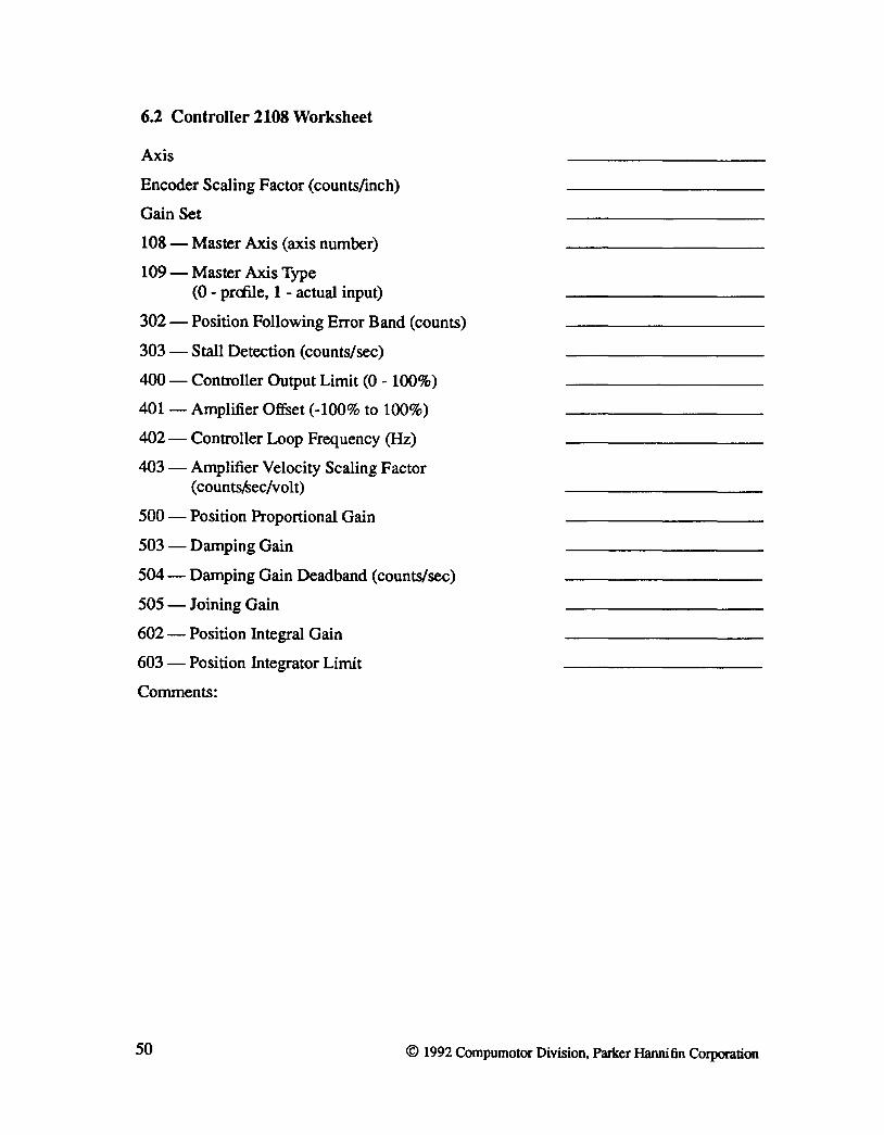
6.2 Controller 2108 Worksheet
Axis
Encoder Scaling Factor (countsfmch)
Gain Set
108 - Master Axis (axis number)
109-Master Axis Type (0 - prcnle, 1 - actual input)
302 - Position Following Error Band (counts)
303 - Stall Detection (counts/sec)
400 - Controller Output Limit (0 - 100%)
401- Amplifier Offset (-100% to 100%)
402 - Controller Loop Frequency (Hz)
403 - Amplifier Velocity Scaling Factor ( countSiSec/volt)
500 - Position Proportional Gain
503 - Damping Gain
504 - Damping Gain Deadband (counts/sec)
505 - Joining Gain
602 - Position Integral Gain
603 - Position Integrator Limit
Comments:
50 © 1992 Compumotor Division, Parker Hannifin Corporation

Enhanced Communication for the
4400 Series Machine Controller Version 1.0

CONTENTS
1. Introduction • • • • • • • • • • • • • • • • • • 51 1.1 Features and Capabilities ••••••••••• 51 1.2 Distribution Disk •••••••••• ••••• 52
2. System Configuration
3. Tenninology • • •
4. Development Environment •
5. Using the Enhanced Communication Features • • • • 5.1 Network Configuration. • • • • • • • • • 5.2 Testing the Configuration • • • • • • •
52
54
55
55 55 57
6. Programming Using the Network ••• ••••••• 58 6.1 Sharing Axis Infonnation . • . • • • • • • 59 6.2 Sharing Variables • • • • • • •• •.••• 60 6.3 Sending Commands. • • • • • • • •• .•••• 61 6.4 Error Handling • • • . • • • . • • . • 61 6.5 Network Management • • • • • • •• •.••.• 64 6.6 Installing the Error Handling and Ivtonitoring the Network State • • • 66
7. Recommendations
8. Example Panelmaker Program •
9. Enhanced Communication Programmer's Reference
10. Error Messages • • • • • • • • . • •
- 1 -
67
68
70
91

LIST OF FIGURES
Figure 1. RS-422 Network Connections
Figure 2. Typical Hardware Configuration for 4400··EC
Figure 3. Structure for Multi-4400 Error Handling •
Figure 4. Network States
© 1992, Compumotor Division, Parker Hannifin Corporation
53
54
63
64
Panelmaker is a registered trademark, and Parasol-II, Lotus 1-2-3 and SEE are trademarks for proprietary software products. IBM is a registered trademark of International Business Machines Corporation. 4400-ECMAN-792
-ii-

Enhanced Communication
1. Introduction
4400-EC, Enhanced Communication, is an installed option for the 4400 Series Machine Controller that allows you to easily send commands, share axis and I/O infonnation, application specific data, and handle error conditions between multiple 44OOs. The Enhanced Communication option simplifies programming for applications that require more than one 4400.
The Enhanced Communication option allows you to connect a number of 4400 Machine Controllers and use them without being required to design, implement, and test a communication protocol. The communication protocol that is used between 4400 is transparent to the user. You specify what infonnation needs to be shared and the Enhanced Communication option takes care of the rest
Developing communications software is often an involved and complicated process. In a typical design, you need to figure out what infonnation needs to be exchanged and how quickly this needs to be done. You need to design, code, and test a communication protocol. Other aspects of the design further complicate the situation. How do you update your operator interface with infonnation from a remote controller? How do you send commands between controllers? How do you deal with an error on one of the controllers?
The Enhanced Communication option provides you with a robust and reliable communication link that allows commands and data to be easily passed between 44OOs. Included with the option is a disk containing a sample program that illustrates a typical application. The routines we provide are designed to be used as a template for your own application.
1.1 Features and Capabilities
4400-EC, Enhanced Communication provides:
• Connection between up to seven 4400 Machine Controllers.
• RS-422 electrical interface.
• Position and velocity for any axis in the system is available on every 4400 on the system.
• The ability to access the state of the first 16 I/O points of any 4400 on the network.
• The ability to specify up to 250 Parasol-II variables whose values may be shared between 4400s on the network.
• The ability for a 4400 to execute an arbitrary interrupt function on any other 4400 on the network.
© 1992 Compumotor Division, Parker Hannifin Corporation. 51

Enhanced Communication
• The ability for a 4400 on the network to detect an error that occurs on another 4400.
1.2 Distribution Disk
44OO-EC comes with one 5 1/4" double-sided, double-density floppy diskette and this manual. The disk contains an example Panelmake,r job and the Parasol-IT software to support the job. The job shows the capabilities of the Enhanced Communication. Example routines which illustrate recommended methods for communicating between 4400 Machine Controllers are also included. These examples can be easily modified to be used in your application. The file called readme. ba t describes the files included on the diskette. To read the contents of this file, put the disk in your A: disk drive and type
a: readme
2. System Configuration
In order to implement a multiple 4400 configuration,. the following hardware is required:
1. Each 4400 should have the 4400-EC option installed.
2. A cable that connects the RS-422 interface (C-5a or C-5b) to each 4400 on the network.
The signals on the C-5a or C-5b connector that are needed are:
9 RS-422RX+ 10 RS-422 RX-14 RS-422 TX+ 15 RS-422 TX-
Figure 1 shows how the cables should be wired between 44OOs. All the RX + and TX+ signals are tied together and all the RX- and TX- signals are tied together.
There is additional hardware required for the development environment. This hardware is not needed during runtime, but having it in your system makes the task of developing your application software significantly easier. The following is needed for the Enhanced Communication development environment:
1. The 44OO-PI option must be installed in each 4400 on the network.
2. A 44OO-COM-P card must be installed in an IBM-PC or compatible.
52 © 1992 Compumotor Division, Parker Hannifin Corporation
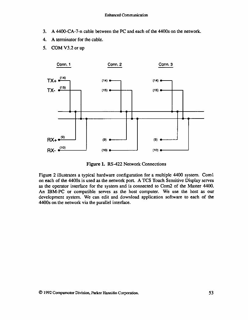
Enhanced Communication
3. A 4400-CA-7 -n cable between the PC and each of the 4400s on the network.
4. A terminator for the cable.
5. COM V3.2 or up
Conn. 1 Conn. 2 Conn. 3
TX+ (14) (14) (14)
TX-(15)
(15) (15)
RX+ (9)
(9) (9)
RX-(10)
(10) (10)
Figure 1. RS-422 Network Connections
Figure 2 illustrates a typical hardware configuration for a multiple 4400 system. Com! on each of the 4400s is used as the network port. A TCS Touch Sensitive Display serves as the operator interface for the system and is connected to Com2 of the Master 4400. An IBM-PC or compatible serves as the host c:omputer. We use the host as our development system. We can edit and download application software to each of the 4400s on the network via the parallel interface.
© 1992 Compumotor Division, Parker Hannifin Corporation. 53

Enhanced Communication
Manager #1 4400 Client #2 4400 Client .n 4400
000 006 660
D 4404 § 4408 § 4408 1 Terminator .. .. ..
_:8 • •
~O ~OO~ ~OO~
n r& nn r& • • • nn r , a~
-,- I Parallel Interface
I ~ ~,2(F!fF!I1 J 0 ·0 Host Computer p <:)0 <:)0
8 8 8 8 8
Serial Interface
D TCS
Figure 2. Typical Hardware Configuration for 4400-EC
3. Terminology
There are several tenns which are used when talking about the network feature of the 4400 that require definition. These include:
Network manager • This is the 4400 that maintains the network after the commands to connect to the network have been issued on each of the 44OOs. In general, the network manager has more infonnation about the state of the network than the network clients. There is only a single network manager while there can be up to six network clients.
Network client • A client 4400 is any 4400 on the network that is not the network manager.
Network number • This is the logical address of a 4400 on the network. The network manager is always assigned network number 1. Network clients have numbers 2, 3, 4, 5, 6, or 7.
54 © 1992 Compumotor Division, Parker Hannifin Corporation

Enhanced Communication
4. Development Environment
The parallel connection between each of the 4400s on the network and the IBM-PC or compatible allows you to communicate with one 4400 at a time. You can download the software the same way you would if you were working with a single 4400. COM (V3.2) has been enhanced to allow you to specify which 4400 you wish to communicate with. You do not have to switch any cables.
In COM, pressing Alt-A allows you to choose the 4400 to communicate with. A window appears which lets you select one of the PI addresses (1-7). You can choose the desired address by moving the highlighted bar over it and pressing ENTER.
Note that each 4400 on the network needs to have its parallel address configured using the Stty command. This should be loaded in the com. c f g portion of the non-volatile memory in the 4400 controller. Please refer to the Non-Volatile Memory section of the 4400 Series Machine Controller User's Guide for additional infonnation on com. cfg. Each of the 4400s should have a unique parallel address. The prompt message on each of the 4400s can be changed so that it is easier to tell which one you are working with. This procedure is described in detail in section 5.1.
S. Using the Enhanced Communication Features
This section describes a step-by-step procedure that may be used to configure your system for Enhanced Communication. Commands used are described more thoroughly in the Programmer's Reference in a later section.
5.1 Network Configuration
The default configuration of a 4400 Machine Controller has the active communication link directed to Coml. To use COM for system development, files are loaded through the active communication link and commands may be tested interactively. In order to configure the network, we need to move the active communication link to the parallel interface in addition to setting up the configuration of the network.
The procedure for setting up the network configuration is given below. These commands should be stored in com. cfg. By storing all the needed commands in the com. cfg file, the 4400 will be automatically set to the desired configuration after powerup of the system.
Note that if you make a mistake in configuring com. cfg, you can always bypass the commands stored there and get to the Parasol-II prompt by connecting to Com1 at 9600 baud and typing two spaces within one second after powerup.
© 1992 Compumotor Division, Parker Hannifin Corporation. 55

Enhanced Communication
• Decide which 4400 will be the network manager. This 4400 is given network number I (using the Netconfig command). The network manager has the most information about the state of the network, so the 4400 in the system that has the TCS Touch Sensitive Display connected to it is normally configured to be the network manager.
The Netconfig command has arguments specifying the network port (Coml or Com2) , the desired network number, and the type of network. If we are are using Coml as our network port, want to assign a network number of I, and wish to use the RS-422 proprietary protocol, the following command line could be used to configure our network manager:
1 1 1 Netconfig
• Change the prompt on the network manager to rn....,p2> by using the command:
Am_A Prompt
Changing the prompt is useful to more easily distinguish the 4400s from one another when using COM and working interactively with multiple 44OOs.
• Specify the address of the 44OO's parallel interface and that the active communication link be the parallel interface (so that the Parasol-II prompt appears at the parallel interface). To avoid confusion, you should make the address of the parallel interface be the same value as the network number assigned. This example assigns a parallel address of 1 to the manager 4400.
1 22 Stty 3 24 Stty
• Specify the network topology on the network manager using the Netmap command.
56
This command specifies how many 4400s are on the network and what their network numbers are. The network will not work if two 4400s are given the same network number.
A command issued on the network manager to specify a network with two clients whose network numbers are 2 and 3 would be:
2 3 2 Netmap
The com. c f g for the network manager of the previous example should look something like this:
Am_A Prompt 1 1 1 Netconfig 2 3 2 Netmap 1 22 Stty 3 24 Stty
© 1992 Compumotor Division, Parker Hannifin Corporation

Enhanced Communication
• Assign each of the other 4400s (clients) a unique network number with the Netconfig command. Issue the commands to specify the parallel interface address and that the parallel interface is the active communication link. Change the prompt on each of the network clients to show that it is a client and to show its network number. At this point, the configuration for the network is complete.
For example, the following commands could be used to set up a 4400 as a client with network number 2 and change the prompt to c2.-p2.
1 2 1 Netconfig 2 22 Stty 3 24 Stty ·c2_ n Prompt
The network client whose network number is 3 will have a corn. cfg that looks like this:
nc3_ n Prompt 1 3 1 Netconfig 3 22 Stty 3 24 Stty
Additional configuration commands may be necessary if you are connecting a touch sensitive display to one of the controllers on the network and wish to operate it at a higher baud rate or if you want to activate the Resource Server. Depending on your system requirements, commands for setting up the other serial ports may also be necessary. These Stty commands may be placed at the front of the corn. c f 9 file.
5.2 Testing the Configuration
You should test the hardware and the software that have been set up. Verification may be performed by following the steps shown below.
• Cycle the power on all of the 4400s on the network to allow them to power up using the new configuration program stored in corn. cfg.
• Go interactive with each of the network clients using COM. Remember that you can choose the 4400 that you wish to communicate with by pressing Alt-A and moving the cursor to the desired parallel address. As in the preceding example, the prompts on the clients should be c2J>2> and c3J>2>. Issue the Netconnect command on each of the clients so that they are ready to begin (there are no parameters for this command).
• Go interactive with the network manager using COM. The prompt mJ>2> should be visible.
• Load the file net_test.p to the network manager using F3 selection in COM. When the file has loaded, the prompt mJ>2> should return.
© 1992 Compumotor Division, Parker Hannifin Corporation. 57

Enhanced Communication
• Type in the command Netconnect followed by a return. This tells the network manager to begin maintaining the network.
• The appropriate communication light on the front panel of each 4400 should begin to flash. The message CUENT # : Connected for each client should be printed to the screen to verify that each client on the network is set up correctly.
If the network does not come up immediately, the steps described below might help you to isolate the problem.
• Check if the communication light for the network port on the network manager is blinking periodically. If not, then either the network communication cable is not connected properly, or the Netconnect command has not yet been issued. Pull the network connector out, check the wiring and plug it back in. Reboot the 4400 by cycling power on the unit, load the net_test.p program, and type Netconnect at the m-p2> prompt
• If the communication light on the manager blinks, but none of the clients connect, something is wrong with the cable or the Netconnect command has not been issued on any of the clients. Issue a Netdisconnect on the manager. Go interactive with one of the clients and issue the Netconnect command. Issue the Netconnect command on the manager. If the client still does not connect, the network cable may not be wired properly.
• If the communication light on the manager blinks, but a client does not connect, there are a number of potential problems that should be checked. The client may be configured incorrectly, the network topology defined on the manager may be wrong, the Netconnect command may not have been issued on the client, or there may be something wrong with the network communication cable. Check the contents of com. c f g on both the manager and the client and make sure that the configurations are correct. Next, issue the Netconnect command on the client. If client still does not connect, pull the connector from one of the c:lients that did connect, and plug it to the client that did not. If the cable is broken, the client should connect now.
6. Programming Using the Network
Once the network has been configured correctly, you can begin design of the data flow between 4400 Machine Controllers. Some issues that you should consider that are application specific are:
• What data must be shared between controllers?
• What commands must be issued between controllers?
• Do the controllers need to be synchronized or do they work independently?
• What information do you want displayed on your operator interface?
• How do you wish to deal with error conditions?
58 © 1992 Compumotor Division, Parker Hannifin Corporation

Enhanced Communication
We have provided sample routines to illustrate some simple methods for the following tasks:
• Sharing axis information
• Sharing variables
• Sending a command to another controller
• Network management
• Error handling
By using our examples as templates for your programming, you will be able to save time in implementing and testing your application.
6.1 Sharing Axis Information
Axis positions and velocities of all axes in the networked system is available to each of the 44oos. Some of these axes are local, in that they are being controlled by the 4400 itself, while others axes are being controlled by other 4400s on the network. For the local axes, axis position and velocity may be read using the Read and Read vel commands, respectively, or may be displayed by using a Panelmaker labeled axis readout. For remote axes, this information is accessed using the Netdata command. For example, to get the position of Zaxis on the 4400 whose network number is 3, the commands issued are:
2 1 3 Netdata 1 Print
Note that this position is the position of the axis at the time of the last scan of the network. The network completes a scan once every 250 msec.
If the axis positions of a client 4400 are needed to update a display on a touch screen on the manager 4400, a timer should be used that would periodically update the positions of the relevant axes. The timer routine would use the Netdata command to set the value of variables to be displayed as readouts and Panelmaker will take care of maintaining the display. This timer should be set up to run once every 200-250 milliseconds. An example using a timer to update the positions of several axes is given below.
Define it_ax-pos
End
; read the positions X and Y axis on 4400 #2 o 1 2 Netdata @.b2_x_ax-pos 1 1 2 Netdata @.b2-y_ax-pos
read the positions A and B axis on 4400 #3 4 1 3 Netdata @.b3_a_ax-pos 5 1 3 Netdata @.b3_b_ax-pos
© 1992 Compumotor Division, Parker Hannifin Corporation. 59
Enhanced Communication
; get a handle for a repetitive timer &it_ax-pos 200 1 'Ihlrget @.tmr_ax-pos ; start up the timer Time 200 + .tmr_ax-pos Tmron
6.2 Sharing Variables
Up to 250 Parasol-II scalar variables can be shared by the network. These are called network variables. Each of these variables is owned by one 4400. The value of the variable should be modified only by the 4400 owning it. All the variables to be shared must be initialized on the network manager before using the Netvadd command to create the variable list.
The variable list must be created on the network manager. This list specifies the variables to be shared and the network number of the owners of the variables. The variable list is only required on the network manager, and is not necessary on the clients. This list must be created while the network is inactive and cannot be modified once the Netconnect command has been issued.
Once this list has been initialized, the variables are shared transparently by the network without any further user intervention. As these variables are changed by the 4400 on the network which owns it, the new value becomes available on any other 4400 on the network. An example function to initialize the list of shared variables is given below.
60
define all the variables to be shared o @.line_speed o @.auto_cycle o @.axisl_rate o @.axis2_rate o @.axis3_rate o @.tension
define a function to initialize the list of shared variables
Define net_v_create &.line_speed 1 Netvadd &.auto_cycle 1 Netvadd &.axisl_rate 1 Netvadd &.tension 2 Netvadd &.axis2_rate 2 Netvadd &.axis3_rate 3 Netvadd
End
© 1992 Compumotor Division, Parker Hannifin Corporation

Enhanced Communication
6.3 Sending Commands
Each 4400 on the network has the ability to generate an interrupt on any specific 4400 or on all other 4400s on the network. The name of the interrupt function to be executed on the target 4400 must be specified. For example, to set the value of the analog output point number 100 to 1024 on the 4400 with network number 2, type the following line at the Parasol-II prompt:
The interrupt function specified must be defined on the target 4400. The function i_analog_out may be defined on the 4400 whose network number is 2 as:
get analog output value 2 Intdata
get analog output point 3 Intdata
output the value to the analog point Dtoa
End
The interrupt function specified must be a user defined function. Parasol-II primitives cannot be executed directly from remote 44oos. Two values may be passed to the interrupt function. Arrays, matrices, or text are not allowed as arguments. These arguments can be accessed from within the interrupt function by using the Intdata command. Also, the address of the 4400 generating the interrupt is available to the interrupt function.
Note that the execution of the interrupt function on the remote 4400 is not synchronous with the Netexe command. There will be a small variable delay between the time the command is issued on the initiator and the time the interrupt is executed on the target.
6.4 Error Handling
Whenever a Parasol-II error or a servo error occurs on any 4400 on the network, the error information becomes available to all the other 4400s on the network. If the RS-422 cable breaks and causes the network to break down, this information becomes available to the network manager and the clients that get disconnected. Other machine specific faults are typically detected by the 4400 responsible for maintaining that part of the system. To make error handling uniform, all fault information should be shared between all 4400s on the network as soon as the fault is detected.
Fault sources can be broadly classified into the following categories:
© 1992 Compumotor Division, Parker Hannifin Corporation. 61

Enhanced Communication
• Local Parasol-II or servo error on the 4400
• Parasol-II or servo error on a remote 4400
• Network error
• Local System fault detected by a 4400
• System fault detected by a remote 4400
Response to the faults will be slightly different on the network manager than it is on the network clients. It will also vary from client to client depending on the machine configuration. For example, if your machine is using a touch display as the operator interface, only one of the 4400s on the network would be set up to display the fault information on the screen.
The fault response will also vary depending on the nature of the machine. If the machine components are tightly coupled, then any fault will typically shut down the complete machine. If there are several independent subsystems, then a fault in one subsystem may not affect the other parts of the machine, so it may not be desirable to shut down the entire machine. In general, it is easier to handle the faults for a tightly coupled system.
Fault handling for a machine with several independent subsystems is highly machine specific. However, some general guidelines are provided here.
Parasol-II and servo related command errors should always shut down the entire machine. These are generated by programming errors, and will be repeated every time the sequence is repeated. These faults typically require changes to the program, and should never happen when the machine is running fully debugged software.
Network faults are unexpected and should be considered a severe error. If the network cable breaks, the machine typically requires corrective action from the operator. Network faults should always shut down the entire machine.
Machine errors, like a position following error, require handling that is machine specific. When a servo error is detected on any axis, it is made available to all the nodes on the network so that fault handling can be perform.ed locally on each 4400.
When other machine specific faults occur, e.g. a guard door opens, the fault should be immediately reported to all the 4400s on the network. The fault reporting must be explicitly handled by the application software. This requires assignment of system wide fault codes, and the response to every fault must be pre-defined. The interrupt functions in response to the fault execute asynchronously with respect to each other on the 44OOs, but within a small time interval. The fault response must be designed with this asynchronous nature in mind. If a synchronous sequence of events is required, they must be performed from the same 4400.
In the example job provided, the system configuration assumed is a three 4400 system with the touch display attached to the network manager. The two client 4400s do not
62 © 1992 Compumotor Division, Parker Hannifin Corporation
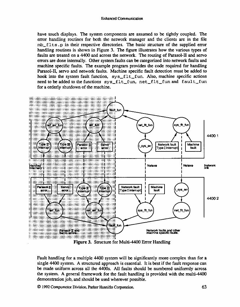
Enhanced Communication
have touch displays. The system components are assumed to be tightly coupled. The error handling routines for both the network manager and the clients are in the file mb_f Its. p in their respective directories. The basic structure of the supplied error handling routines is shown in Figure 3. The figure illustrates how the various types of faults are treated on a 4400 and across the network. The routing of Parasol-II and servo errors are done internally. Other system faults can be categorized into network faults and machine specific faults. The example program provides the code required for handling Parasol-II, servo and network faults. Machine specific fault detection must be added to hook into the system fault function, sys_f I t_fun. Also, machine specific actions need to be added to the functions sys_flt_fun, net_fIt_fun and fault_fun for a orderly shutdown of the machine.
: Net&X8
I
Network faul~.and other machine Specific fauItB.
Figure 3. Structure for Multi-4400 Error Handling
: Net&xe
I
Fault handling for a multiple 4400 system will be significantly more complex than for a single 4400 system. A structured approach is essential. It is best if the fault response can be made uniform across all the 44OOs. All faults should be numbered uniformly across the system. A general framework for the fault handling is provided with the multi-4400 demonstration job, and should be used wherever possible.
© 1992 Compumotor Division, Parker Hannifin Corporation. 63
44001
44002

Enhanced Communication
6.5 Network Management
In most situations, the network provides an extremely robust communication link that requires virtually no attention at runtime. If the software provided with the Enhanced Communication option is used, the amount of development effort required will be minimized. However, it is essential to understand the functioning of the network in order to debug the system when something goes wrong with the network. This section briefly describes the various states of the network, events that trigger a change of state and error conditions that may be generated. Figure 4 illustrates the network states.
Network States
Manager looking at Client Network states for Client
Netdisconnect Powerup Netdisconnect Powerup
Connect Disconnect
Poll timeout
Poll
Figure 4. Network States
All the nodes must be configured first, and the network topology must be described on the network manager. After the nodes have been configured and the topology defined, issuing a Netconnect command enables each of the nodes to connect to the network. The network manager is always in charge of maintaining the network.
To the manager, a client can have only two states, connected or disconnected. The initial state of every client after power up is disconnected. The state changes when the client connects after the Netconnect command is issued. Connecting with a client generates an
64 © 1992 Compumotor Division, Parker Hannifin Corporation

Enhanced Communication
interrupt on both the manager and the client.
To the network manager, the state can change back to disconnected only if the Netdisconnect command is issued on the manager or on the client, or the client is physically removed from the network by either powering it down or by pulling the communications connector. If the Netdisconnect command is issued on the manager, then the state change is known, and no interrupt is generated. If the client disconnects under any other condition, an interrupt is generated on the manager. Error handling on the 4400 runs at a higher priority than the operation of the network so a long running error handling routine (greater than 1 second) can cause network disconnect.
The network client can also have the same two states, connected or disconnected. The initial state after power up is disconnected. When the manager connects to it, the state changes to connected, and an interrupt is generated on the client. When the manager explicitly disconnects the client, the state changes to disconnected, and an interrupt is generated on the client.
In addition to its own state, the client also tracks the state of the network manager. Since the manager is responsible for maintaining the network, the client monitors for sustained network activity. When the client connects to the manager, the state of the manager is set to active. While the manager is active, the state of the manager as seen by the client stays unchanged.
However, if network activity ceases for a long time (approximately 2 seconds), the client changes the manager's state to idle, and an interrupt is generated on the client. This can happen when the network manager is powered down, or the connector is removed. The state of the manager goes back to active only after it resumes network activity.
Normally, once the nodes connect, they will remain connected. If a node disconnects, it should be treated as a severe error condition and the system should be shut down. If the state of the network manager goes to idle, it is potentially a severe error condition. In the software provided with the package, this condition triggers a timer. If the manager does not resume network activity by the time the timer has expired, the system is immediately shut down.
Two other situations are treated as error conditions. Both the manager and the clients have a transmit fail condition. This error should never occur. The other condition is a receive fail condition. This can be induced by severe external disturbances, such as high voltage, high frequency carrying conductors being bundled with the communication cables, or the communication cable having an intermittent connection. The software provided with the package is set up to track these errors, and to shut down the system if these errors happen frequently.
Complete software for handling all the network conditions is provided on the application disk. Hooks are provided so that this software can be integrated into your application easily. These should be adequate for any application requiring networked 44OOs. Minor changes may be made to customize the software for specific applications without going
© 1992 Compumotor Division, Parker Hannifin Corporation. 65

Enhanced Communication
beyond the framework provided.
6.6 Installing the Error Handling and Monitoring the Network State
Parasol-II application software is provided that can be used by your job as a framework for the network management and error handling. The system configuration assumed is a tightly coupled system, with a touch display connected to the manager. The steps described below illustrate how you can use this software.
• Run Panelmaker without communicating with the 4400 (pm -n). Cut and paste the single panel from the job net_err into your job. Exit Panelmaker, saving the job as you go.
• The application software is partitioned into two directories, mgr and client. They contain network management and error handling software for the network manager and the clients respectively.
In the mgr directory, the file net_mgr . p contains the network management routines, the file netm_err. p contains the error handling routines, and the file netc_glb. p contains constant and variable declarations used by both the error handling and network management routines.
In the client directory, the file net_clnt.p contains the network management routines, the file netc_err. p contains the error handling routines, and the file netc_glb.p contains constant and variable declarations used by both the error handling and network management routines.
Copy the files into appropriate directories of your job, and include the file names in your nonvol. def for each 4400. For the clients, set the network address of the 4400 correctly in the file netc_glb .p.
• The network management software must be interfaced to your application software. You need to define the routine net_v_create on the network manager to initialize the list of network variables. Refer to the Section 6.2 which describes shared variables for an example. On the clients, this function does not need to be defined. To install the software, call the function net_ini t from your system initialization code.
The net_ini t routine will call the net v create routine on the network manager, install the network interrupt routines, and start up the network.
• At this point, the network management software has been interfaced to your application software, and the Parasol-II error handling has been installed. What remains to be done is to interface the system fault detection to the system fault handling, and to provide the code required for an orderly shutdown of the system when a fault occurs. First, create a list of all possible system faults. Assign sequential numbers to them starting with 7, and add to the list of system faults in the files netm_glb. p and netc_glb. p.
66 © 1992 Compumotor Division, Parker Hannifin Corporation

Enhanced Communication
• In the file netm_err . p, modify the value assigned to the variable .num_faults to be equal to the last system fault code assigned. Add fault messages to the list of system fault messages stored in the variables --pm_flt#. Initialize the elements of the Apm_faults array with the new fault messages added .
• Add machine specific action to the functions sys_flt_fun, net_fit_fun and fault_fun in both the files netm_err. p and netc_err. p.
• In your application software, whenever a machine fault is detected, set the variable . sys_f 1 t_code to the appropriate fault code from the list defined above, and branch to the system fault handling routine with a &sys_f 1 t_fun Res tart.
The function should take care of sharing the fault information with the other 4400s on the network, displaying the fault on the touch display if necessary and shutting down the machine in an orderly manner.
7. Recommendations
There are several rules of thumb which are useful to keep in mind when programming a multi-4400 system. These include:
1. The network option will be very robust. You should plan to initialize and connect the network on powerup of the system (as described previously) and then forget about it.
2. Although the network is robust, there are some problems that will cause it to go down, for instance when the RS-422 cable is cut. Make sure that your program does something safe when the network goes down. A normal part of your software development process should be to physically disconnect and reconnect the RS-422 cable from a 4400 (or 4400s) on the network to determine your program can handle and recover from network errors.
The error handling routines we supply illustrate reasonable recovery techniques but the routines may need modification to be appropriate for your particular application.
3. When a network variable is defined as being owned by a certain 4400, the value of that variable should not be changed by any other 4400 on the network.
4. It is probably easiest if you use as much of the example code we provide as possible.
5. Whenever possible, pieces of a system which are closely related should be controlled by a single 4400. For example, if your machine has an I/O point to turn on a drill spindle, an I/O point to turn on the lubricant for the drill, and an axis to feed and retract the drill, these should all be controlled from a single 4400.
© 1992 Compumotor Division, Parker Hannifin Corporation. 67

Enhanced Communication
6. Try to send as few commands as possible between 44OOs. A multi-44OO system is easiest to program and debug when the software on each of the 4400s runs relatively independently during normal operation.
8. Example Panel maker Program
Example Panelmaker jobs are included on the distribution disk that should make it easier for you to develop your application.
The \pm directory contains example programs that can be used with Panel maker. The net_err job contains a single screen that allows the error handling routines provided on the distribution disk to be integrated into your application software. The net_err. pm file is in the \pm\ usr directory. The directory \pm\ usr\net_err contains the Panelmaker generated files for the screen and two subdirectories. The \pm\usr\net_err\mgr directory contains the software that goes on the network manager along with the error screen. The \pm\usr\net_err\client directory contains the support software for the clients.
A Panelmaker job called mul t i is also provided on the distribution disk. This is a working application for a three 4400 system that demonstrates a number of the network features and can be used as an example program to show how to program typical application functions such as:
1. Updating position information from a client 4400 on the touch screen.
2. Sending a command to a client 4400 to cycle an axis using a button on the touch screen.
3. Programming variables as shared between 4400s (network variables).
4. Error handling on a multi-44OO system.
The multi job is divided into two subdirectories under the \pm\usr\multi directory. The \pm\usr\multi \mgr directory contains software for the network manager. The file rob. def contains the list of files to be loaded to the manager. The directory \pm\usr\multi \client contains software for the clients. The file rob . de f contains the list of files to be loaded to the clients.
For a two 4400 system, edit the file mb_glob.p in the directory of the manager, and set the variable .bam3_netstat to DISCONNECTED. For a three 4400 system, copy the contents of the client directory to another directory. Edit the rob_glob. p file in the client directory, and change the value of the variable . net_addr to 3.
An installation program is provided on the distribution disk to install the Panelmaker jobs. For example, if your Panelmaker directory is in the c: drive, type
68 © 1992 Compumotor Division, Parker Hannifin Corporation

Enhanced Communication
install c:
at the DOS prompt This program copies the two jobs to the \pm directory on the c: drive.
© 1992 Compumotor Division, Parker Hannifin Corporation. 69

Enhanced Communication
9. Enhanced Communication Programmer's Reference
The following pages describe additional Parasol-II commands that are used with the Enhanced Communication option (4400-EC). The following commands are included:
70
Intdata
Netconfig
Netconnect
Netdata
Netdisconnect
Netexe
Netmap
Netstat
Netvadd
Netvdel
Onnet
Prompt
Stty
Get data associated with a particular interrupt.
Set up the network address, network port, and network type. This command is normally issued once on powerup.
Tell the 4400 to attempt to get on the network. This command is normally issued once on powerup after the network variable list has been constructed.
Get information about the data that is passed between the 4400 Machine Controllers on the network.
Tell the 4400 to drop off the network. This command will not be used in normal circumstances.
Execute an interrupt function on a remote network node.
Describe the topology of the network. This command will normally be issued once on powerup by the network manager.
Get information about the state of the network.
Add variables to the list of network variables. This command is only used on the network manager.
Clear the list of network variables. This command is only used on the network manager.
Specify the interrupt service routines for interrupts generated by the network.
Prepend a string to the Parasol-II prompt
Select the communication protocol options for the 4400 Machine Controller.
© 1992 Compumotor Division, Parker Hannifin Corporation

Enhanced Communication Intdata
NAME:
Intdata
FUNCfION:
Intdata is a command used to get data associated with a particular interrupt. An example usage is:
.data_num Intdata
At the time of an event which causes an interrupt, a snapshot of certain machine data is taken. The Intdata command may be used (only) within an interrupt function to access this machine snapshot.
Currently, there are three data elements per interrupt function. These data elements are different depending on the type of event which generated the interrupt The available data is:
• Industriall/O:
1 - time (milliseconds)
2 - number of the input which generated the interrupt
• Dedicated Input:
1 - time (milliseconds)
2 - position of the axis with which the switch is associated
• Timer:
1 - time (milliseconds)
2 - timer number which generated the interrupt
Be sure to note that the data for the Industrial I/O, the Dedicated Inputs, and the Timers is from the time at which the event occurred, not the (later) time at which the interrupt service function executes.
• Network Error:
1 - type of error
2 - data related to type of error
3 - data related to type of error
See the Command Reference page for Onnet for more information.
• Parasol-II Errors from another network node:
1 - Network number of the node that had the error
© 1992 Compumotor Division, Parker Hannifin Corporation. 71

Intdata
2 - Number of the error
3 - Axis Number (for axis command errors)
See the Command Reference page for Onnet for more information.
• Axis Errors from another network node:
1 - Network number of the node that had the error
2 - Number of the error (negative)
3 - Axis Number for the axis on which the error occurred
See the Command Reference page for Onnet for more information.
• Network Command:
1 - Network number of the 4400 initiating the command
2 - Argument for the command (optional)
3 - Argument for the command (optional)
See the Command Reference page for Netexe for more information.
ARGUMENTS:
Intdata requires one argument; the number of the data element to be returned. This number must be either 1,2, or 3.
RETURNS:
Intdata returns the value of the requested data.
EXAMPLE:
72
Consider a registration sensor which triggers a Dedicated Input. The result of the registration is used to adjust the position of an axis which is moving a product in front of the sensor.
Define id_register
End
Read the position at which the input went true. 2 Intdata @.reg-pos
Determine the difference between the theoretical ; sensor position and the measured sensor position . . theo_reg-pos .reg-pos -
; Adjust the phase of the appropriate axis. Yaxis Phase
© 1992 Compumotor Division, Parker Hannifin Corporation

Intdata
NOTES:
Notice that the Intdata command returns data that is relevant only in the context of an interrupt service function. Issuing this command from the Parasol-II prompt or from the main program will generate an error.
SEE ALSO:
Netexe, Oninput, Onnet, Onswit, Tmrget
© 1992 Compumotor Division, Parker Hannifin Corporation. 73

Netconfig
NAME:
Netconfig
FUNCflON:
Netconfig is the command used to configure the network. A sample usage is:
.port .net_num .type Netconfig
where . port is either 1 or 2, specifying either coml: or com2: on the 4400, . net_num specifies the network number of the 4400, and . type is the type of network. The only type of network currently supported is type 1, specifying the 4400 proprietary protocol using RS-422. The 4400 whose network number is set to 1 is the network master. 4400s with network numbers in the range of 2 - 7 are network clients. All other network numbers are illegal.
ARGUMENTS:
Netconfig requires two arguments; the network port, the network number, and the network type.
RETURNS:
Netconfig has no return values.
EXAMPLE:
Configure a 4400 to be the manager of a network connected on com2:
p2> 2 1 1 Netconfig
NOTES:
Specifying two network clients with the same network numbers or two network managers will result in unpredictable network behavior.
Normally, this command need only be issued once on powerup of the system. We recommend that this and other setup commands be stored in the non-volatile com. c f g file in the 4400 Machine Controller so that the 4400 is automatically set to the desired configuration after powerup of the system.
SEE ALSO:
Netconnect, Netdisconnect, Netmap
74 © 1992 Compumotor Division, Parker Hannifin Corporation

Netconnect
NAME:
Netconnect
FUNCfION:
Netconnect is the command used start the 4400 to 4400 network. A sample usage is:
Netconnect
When used on the network manager, this command starts the entire network. When used on a network client, this command simply makes it possible for the network manager to recognize the client on the network.
ARGUMENTS:
Netconnect requires no arguments.
RETURNS:
Netconnect has no return values.
EXAMPLE:
Start the network:
p2> Netconnect
NOTES:
Normally, this command only need to be used once on powerup of the system.
SEE ALSO:
Netconfig, Netdisconnect, Netmap
© 1992 Compumotor Division, Parker Hannifin Corporation. 75
Netdata
NAME:
Netdata
FUNCTION:
Netdata is the command used to get infonnation about the data that is passed between 4400 Machine Controllers on the network. A sample usage is:
.qualifier .data_type .net_num Netdata
where . qualifier and . data_type specifies the data which is requested and . net_num specifies the network number of the 4400 whose data is requested.
Currently supported values for . data_type include:
1 Axis position. For this data type, .qualifier should be the number specifying the desired axis (0 - 7).
2 Axis velocity. For this data type, .qualifier should be the number specifying the desired axis (0 - 7).
3 Industrial I/O state data. For this data type, . qualifier should be the number specifying the I/O in question (0 - 15).
10 The number of times that the specified 4400 has completed transfer of the network variables that it owns. For this data type, no . qualifier is necessary.
20 The number of slots available in the network interrupt buffer (see Netexe). For this data type, no . qua 1 i fie r is necessary.
21 The total number of slots in the network interrupt buffer (see Netexe). For this data type, no . qua 1 i fie r is necessary.
ARGUMENTS:
Netdata requires three arguments; one or two arguments specify the type of data requested and one argument specifies the network number of the 4400 where the data originates.
RETURNS:
Netdata has a single return value; the value of the requested data.
EXAMPLE:
Check the position of the Yaxis on a 4400 whose network number is 3.
p2> 1 1 3 Netdata
NOTES:
76
The classification for the .data_type parameters listed above is between 1 and 9 when data comes from a remote node, between 10 and 19 when the data comes
© 1992 Compumotor Division, Parker Hannifin Corporation

Netdata
either from a remote node or locally, or between 20 and 29 when the data comes from the local 4400 Machine Controller.
SEE ALSO:
Netexe, Netstat
© 1992 Compumotor Division, Parker Hannifin Corporation. 77

Netdisconnect
NAME:
Netdisconnect
FUNCflON:
Netdisconnect is the command used to stop the 4400 to 4400 network. A sample usage is:
Netdisconnect
When used on the network manager, the Netdisconnect command will kill the entire network. When used on a network client, this command will just take that client off of the network.
ARGUMENTS:
Netdisconnect requires no arguments.
RETURNS:
Netdisconnect has no return values.
EXAMPLE:
Stop the network:
p2> Netdisconnect
NOTES:
Under normal circumstances, this command will never be used.
SEE ALSO:
Netconfig, Netconnect, Netmap
78 © 1992 Compumotor Division, Parker Hannifin Corporation

Netexe
NAME:
Netexe
FUNCI10N:
Netexe is the command used to execute an interrupt function on another 4400. A sample usage is:
.param2 .param3 • function· .net_num Netexe
where . net_num is the network number of the 4400 which is to execute the function, • function· is the name of the function to be executed, and .pararn2 and . pararn3 are the parameters which will be available to the executing functions through the Intdata command.
If . net_nurn is -1, the interrupt function will execute on all 4400s which are connected to the network.
The interrupt function (which executes on the 4400 whose network number is specified by . net_nurn) will have access to the address of the network node which generated the interrupt (using 1 Intdata) and to . pararn2 and . pararn3 (using 2 Intdata and 3 Intdata, respectively).
ARGUMENTS:
Netexe requires four arguments; the network number of the 4400 which is to execute an interrupt function, the name of the function to be executed, and two parameters to be passed to the executing function.
RETURNS:
Netexe has no return values.
EXAMPLE:
Run the function called upda t e_s tat us with the parameters 526 and .3333 on the 4400 whose network number is 3:
p2> 526 .3333 ·update_status· 3 Netexe
NOTES:
The function to be executed must be defined on the target 4400 and must be a user defined function (for example, the Nvformat command may not be executed across the network).
Commands to execute functions on a different network node are buffered internally and sent out over the network when the network becomes available. At anyone time, only five network commands may be pending. Attempts to send more than five commands over the network at the same time will generate Error 138, Too many Netexe commands pending. The number of commands currently in the buffer and
© 1992 Compumotor Division, Parker Hannifin Corporation. 79

Netexe
the number of spaces available in the buffer can be determined using Netstat.
Under normal network conditions, a single network node can send five commands every 250 milliseconds.
SEE ALSO:
Intdata, Netstat
80 © 1992 Compumotor Division, Parker Hannifin Corporation

Netmap
NAME:
Netmap
FUNCTION:
Netmap is a command used only on the network manager to specify the network topology. A sample usage is:
.net_num .... net_2 .net_l .num Netmap
where . num is the total number of network clients which need to be serviced by the network manager and the . net values are the network numbers of the clients to be served.
The total number of nodes on the network (including the network manager) is equal to .num + 1.
The network numbers specified using the Netmap command on the network manager should match the network numbers specified with Netconfig on the client 4400s.
ARGUMENTS:
Netmap requires an argument specifying the number of client nodes on the network and one argument per node specifying the network number of the node.
RETURNS:
Netmap has no return values.
EXAMPLE:
Configure a network with three client nodes with network numbers 2, 3, and 4:
p2> 2 3 4 3 Netmap
Notice that this network will have four nodes in total (including the network manager).
NOTES:
This command may be executed only on a 4400 previously specified as the network manager (using Netconfig).
Normally, this command only need to be used once on powerup. We recommend that this and other setup commands be stored in the non-volatile com. c f 9 file in the 4400 Machine Controller so that the 4400 is automatically set to the desired configuration after powerup of the system.
SEE ALSO:
Netconfig, Netconnect, Netdisconnect
© 1992 Compumotor Division, Parker Hanni fin Corporation. 81

Netstat
NAME:
Netstat
FUNCflON:
Netstat is the command used to determine the state of the network. A sample usage is:
.pararn .net_nurn Netstat
where . pararn specifies the network status value which is desired and . net_nurn is the network number for the desired 4400 Machine Controller. Currently supported values include:
1 returns whether the network is connected (1), disconnected (0), timed out for a client (-1).
ARGUMENTS:
Netstat requires two arguments; the type of network status desired and the network number of the 4400 that is being checked.
RETURNS:
Netstat returns a single value which is dependent on the status being checked.
EXAMPLE:
Write a function to determine whether or not the network is connected:
p2> Define is_net_conn dffn> 1 Netstat If true dffn> "Network connected n Pmsg dffn> Else dffn> "Disconnected" Pmsg dffn> Endif dffn> End p2>
NOTES:
The state of all the clients is available on the network manager. A network client only knows its own state.
SEE ALSO:
Netconfig, Netconnect, Netdisconnect, Netmap, Netvadd
82 © 1992 Compumotor Division, Parker Hanni fin Corporation

Netvadd
NAME:
Netvadd
FUNCfION:
Netvadd is the command used on the network manager to add variables to the pool of network variables. A sample usage is:
&.val .net_num Netvadd
where . net_nurn is the network number of the 4400 which is to transmit the variable, and . val is the variable which is to be transmitted.
One node on the network owns each network variable in that it sends the current value of that variable to all of the other network nodes.
ARGUMENTS:
Netvadd requires two arguments; the network number of the 4400 which is to transmit the network variable, and the address of the network variable.
RETURNS:
Netvadd has no return values.
EXAMPLE:
Add variables called .baml_state and .bam2_state to the pool of network variables.
p2> &.baml_state 1 Netvadd p2> &.bam2_state 2 Netvadd
Note that in the above example, . baml_state will be transmitted by the network manager (whose network number is always 1) and . bam2_state will be transmitted by the client with network number 2.
NOTES:
This command may be executed only on the network manager. The variable to be shared must be initialized before using this command. Netvadd may not be executed when the network is connected.
Each network node may transmit at most 40 network variables. A total of 250 network variables are allowed. The network variables must be initialized before they are added to the network variable list.
SEE ALSO:
Netdata, Netvdel
© 1992 Compumotor Division, Parker Hannifin Corporation. 83
Netvdel
NAME:
Netvdel
FUNCflON:
Netvdel is the command used on the network manager to clear the pool of network variables. A sample usage is:
Netvdel
ARGUMENTS:
Netvdel requires no arguments.
RETURNS:
Netvdel has no return values.
EXAMPLE:
Disconnect the network, delete the pool of network variables, and reconnect the network (with no network variables):
p2> Netdisconnect Netvdel Netconnect
NOTES:
This command may be executed only on the network manager.
This command may not be executed when the network is connected.
SEE ALSO:
Netvadd
84 © 1992 Compumotor Division, Parker Hannifin Corporation

Onnet
NAME:
Onnet
FUNCI10N:
Onnet is the command used to set up the functions which execute when certain conditions are detected by the network. A sample usage is:
&in_func .type Onnet
where in_func is the address of the Parasol-IT interrupt function to execute, and . type specifies the type of condition which is being routed. The following conditions cause interrupts:
1 Nodes on the network get interrupts when the state of the network changes. These interrupts are routed to the function specified by using . type 1.
2 All nodes on the network get an interrupt when a node has a Parasol-II error. These interrupts are be routed to the function specified by using . type 2.
3 All nodes on the network get an interrupt when a node has an axis related error. These interrupts are be routed to the function specified by using . type 3.
Information regarding the condition which generated the interrupt is returned by the Intdata command.
The following conditions will be routed to the type 1 function:
1 Any 4400 gets an interrupt when it fails to transmit data. When called with the argument shown, the Intdata command returns:
1. Ai, specifying that data transmission has failed.
10 The network manager gets an interrupt when a client connects. When called with the argument shown, the Intdata command returns:
1. A 10, specifying that the network manager detected a connection.
2. The network number of the client that connected.
11 The network manager gets an interrupt when a client disconnects. When called with the argument shown, the Intdata command returns:
1. An 11, specifying that the network manager detected a disconnection.
2. The address of the client that connected.
12 The network manager gets an interrupt when any network transmission is garbled. When called with the argument shown, the Intdata command returns:
1. A 12, specifying that a transmission has been garbled.
© 1992 Compumotor Division, Parker Hannifin Corporation. 85

Onnet
20 A client on the network gets an interrupt when it connects to the network manager. When called with the argument shown, the Intdata command returns:
1. A 2 0, specifying that a connection has occurred.
21 A client on the network gets an interrupt when the network manager issues the Netdisconnect command and kills the network. When called with the argument shown, the Intdata command returns:
1. A 21, specifying that a disconnection has occurred.
22 A client on the network gets an interrupt when the network manager fails to maintain the network. When called with the argument shown, the Intdata command returns:
1. A 22, specifying that the network has ceased to be maintained.
This interrupt may be generated under a number of conditions, for instance if power to the network manager is cut or if the error handling function on the network manager runs for an extended period of time.
23 A client on the network gets an interrupt when the network manager resumes maintaining the network. When called with the argument shown, the Intdata command returns:
1. A 2 3, specifying that the network is being maintained.
This interrupt occurs only after interrupt 22 has occurred.
When a node on the network has a Parasol-II error, all other nodes on the network will get an interrupt which executes the function specified using type 2 of Onnet. When called with the argument shown, the Intdata command returns:
1. The address of the node which had a Parasol-II error.
2. The number of the error (this number will be positive).
3. The axis on which the error occurred if this is a servo command error or -1 for a non-axis specific command error.
When a node on the network has an axis error, all other nodes on the network get an interrupt which executes the function specified using type 3 of Onnet. When called with the argument shown, the Intdata command returns:
1. The address of the node which has an axis error.
2. The axis on which the error occurred.
3. The number of the error (this number will be negative).
ARGUMENTS:
Onnet requires two arguments; the address of the interrupt service function and the
86 © 1992 Compumotor Division, Parker Hannifin Corporation
Onnet
type of error to be serviced.
RETURNS:
Onnet has no return values.
EXAMPLE:
Set up functions to run when certain conditions are detected by the networking facilities:
p2> &in_net_err 1 Onnet p2> &in-p2_err 2 Onnet p2> &in_axis_err 3 Onnet
The in_ function name prefix signifies that this is an interrupt function which executes as a result of a network event.
NOTES:
Under nonnal circumstances, this command will be issued once on powerup to route network errors, once on powerup to route network node Parasol-II errors, and once on powerup to route network node axis errors.
SEE ALSO:
Intdata
© 1992 Compumotor Division, Parker Hannifin Corporation. 87
Prompt
NAME:
Prompt
FUNCflON:
Prompt is a command used to prepend a string to the Parasol-II prompt It is useful for distinguishing 4400s during development when a system has multiple 4400 Machine Controllers. A sample usage is:
"string" Prompt
where string is the text string to be prepended to the Parasol-II prompt
ARGUMENTS:
Prompt requires an argument specifying the string to be prepended to the Parasol-II prompt
RETURNS:
Prompt has no return values.
EXAMPLE:
Change the Parasol-II prompt to c2-p2 >.
p2> nc2_ n Prompt c2-p2>
NOTES:
A maximum of 6 characters may be prepended to the Parasol-II prompt
SEE ALSO:
Netconfig, Netmap
88 © 1992 Compumotor Division, Parker Hannifin Corporation

Stty
NAME:
Stty
FUNCfION:
Stty is the command used to select the communication protocol options for the 4400 Machine Controller. If the 4400 controller has the high speed parallel interface installed, then many of the options are not relevant. This command sets a single option at a time on the active communication link. It may have to be executed a number of times for each communication link to completely set the protocol in the desired manner.
A brief summary of the usage and the option for the Stty command is given below:
Host Link Configuration Options
0 Stty
1 Stty
2 Stty
3 Stty
4 Stty
baud 20 Stty
prnt 21 Stty
addr 22 Stty
com 24 Stty
fmt 25 Stty
Reset the Communication Protocol to the Power-up Default Mode
Enable the Parasol-II Prompt Message
Disable the Parasol-II Prompt Message
Turn the input echo on
Turn the input echo off
Choose the baud rate.
Enable (pmt = 1), or disable (pmt = 0) diagnostic error message printing.
Set the parallel interface address (1-7)
Choose the active communication link com = 1, communicate via COMI com = 2, communicate via COM2 com = 3, communicate via the high speed parallel interface
Select the serial data format. fmt = 0, 8 data bits, 1 stop bit, no parity fmt = 1,8 data bits, 1 stop bit, odd parity fmt = 2, 8 data bits, 1 stop bit, even parity
4400 Input Protocol Options (select one):
5 Stty
6 Stty
8 Stty
Verbatim Echo
Echo Off With Acknowledge of Each Line Received
XON/XOFF Input Flow Control
© 1992 Compumotor Division, Parker Hanni fin Corporation. 89

Stty
4400 Output Protocol Options (select one):
10 Stty
11 Stty
12 Stty
DTR Output Control
XON/XOFF Output Control
Transmit on Inquiry
Communication Protocol Characters:
ack 15 Stty Choose the Line Acknowledgement Character
nak 16 Stty Choose the Error Acknowledgement Character
eol 17 Stty Choose the Input End of Line Character
inq 18 Stty Choose the Inquiry Character
Resource Server Option:
1 26 Stty
o 26 Stty
RS-422
o 27 Stty
1 27 Stty
Activate the Resource Server
Deactivate the Resource Server
Switch serial port to RS-232
Switch serial port to RS-422
ARGUMENTS:
The number of arguments needed by Stty depends on the protocol option to be specified. See above.
RETURNS:
Stty has no return values.
EXAMPLE:
Set the active communication link: for Com 1, Parasol-II prompt off, echo on, XON/XOFF input control and XON/XOFF output control.
p2> 1 24 Stty 2 Stty 3 Stty 8 Stty 11 Stty
NOTES:
90
The baud rate, serial data format, input protocol, and output protocol options do not apply to the high speed parallel interface.
The high speed parallel interface uses a hardware handshake protocol.
© 1992 Compumotor Division, Parker Hannifin Corporation

Enhanced Communication
10. Error Messages
The following list describes the error messages that may be generated by the 4400 Machine Controller if one of the Enhanced Communication commands is issued incorrectly or at an inappropriate time.
130 Bad input to a Net command (often bad network number).
131 Net command allowed on network manager only.
132 Invalid network map specified using Netmap.
133 Command not allowed until network is configured.
134 Network command issued at inappropriate time.
135 Failed to add a network variable.
137 Request for unknown data with Netdata.
138 Too many Netexe commands pending.
139 Attempt to execute non-user defined function with Netexe.
© 1992 Compumotor Division, Parker Hannifin Corporation. 91

Resource Server 1M
for the
4400 Machine Controller Version 1.0

CONTENTS
1. Introduction • • • • • • • • 1.1 Features and Capabilities • 1.2 Distribution Disks • • • • .
2. System Configuration and Installation • • • • • • • • • • 2.1 System Configuration • • • • • • • • 2.2 Program Installation • • • • • • • • • • • • • • • • 2.3 Making Backup Copies of the Distribution Disks •
3. Tutorial for the Resource Server 3.1 Development Environment 3.2 Basic Concepts • • • • • • 3.3 Device Handling • • • • • 3.4 Blocking and Non-blocking I/O • 3.5 File Services. • • . • . . 3.6 Additional Features •••. 3.7 Examples. . • • • • . .
4. Resource Server Command Summary
5. Device Driver Software Interface.. ••• ••• 5.1 Setting Up the Development Environment • ••• 5.2 Designing the Device Driver • • • • • • • • • • • • • • 5.3 Compiling and Linking Device Drivers. • • • • • • 5.4 Device Driver Function Calls .••.•••• •••
A. Glossary of Terms
- 1 -
93 93 94
95 95 96 96
99 99
101 102 102 103 106 109
112
136 136 139 140 141
150

LIST OF FIGURES
Figure 1. 4400-RS System Configuration
Figure 2. Development Configuration
Figure 3. Runtime Configuration •
© 1992, Compumotor Division, Pdrker Hannifin CotpOration
96
100
101
Panelmaker is a registered trademark, and Resource Server and Parasol-II are trademarks for proprietary software products. IBM is a registered trademark of International Business Machines COtpOration. 4400-CAMMAN-792
-ii-

Resource SelVer - Introduction
1. Introduction
4400-RS, Resource Server, is an installed option of the 4400 Machine Controller which provides flexible and simple access to disk files and external devices controlled by an mM-AT. Disk files can expand the storage capability of the 4400 controller for part programs, SPC data, exception logging, and other mass storage requirements. Because floppy disks are removable mass storage devices, off-line part programming and archiving are facilitated with 4400-RS. In addition to providing direct disk file access for the 4400, the Resource Server connects the PC bus and the devices on it to the 4400. Bar code readers, vision systems, network interfaces, or any other device that can be installed on the PC bus can be directly accessed with the 4400 Resource Server.
44OO-RS consists of enhanced capabilities installed in the 4400 controller that pennit direct control of files and devices on the PC. Initialization, reading, writing, opening, closing, status and error checking, and direct system calls are included in the Resource Server's functionality. For the 4400 to exercise this control o~PC based devices, the PC must be running either COM (V3.1 or above) or Panelmaker (V1.3 or above). While running either of these two programs, a 4400 controller equipped with 44OO-RS will have direct access to PC based disk files. Because 4400-RS provides the flexibility to control any device on the PC bus, a convenient method is provided to customize COM with device drivers that you write for the specific devices in your system. This customized COM can be used during both system development and machine operation. It is not necessary to customize Panelmaker with these device drivers, since Panelmaker is used only in a development mode and not during actual machine operation.
4400-RS can operate over either of the two serial ports on the 4400 or the optional high speed parallel port, 4400-PI. If you require only file services, interconnect the 4400 and the PC to the appropriate communication ports, run COM or Panelmaker. and begin using the 4400-RS Parasol-II commands. It's as simple as that.
1.1 Features and Capabilities
Resource Server Version 1.0 provides:
• Access to DOS file system on PC • Interface to eight external devices • Access to devices through Parasol-II commands • Access to host PC's operating system shell • Blocking and non-blocking access modes • Program development environment • Run-time support
© 1992 Compumotor Division. Parker Hannifin Corporation 93

Resource Server - Introduction
1.2 Distribution Disks
4400-RS comes with one 5 1/4" double-sided, double-density floppy diskette and this manual. The disk contains an executable version of COM (V3.1) that includes file system support. Libraries, object files and make files for creating an executable customized COM, templates for device drivers, and sources for an example device driver are included to facilitate creating and installing custom device drivers into COM. Refer to the readme. doc file on the distribution disk for a list of files provided.
94 © 1992 Compumotor Division, Parker Hannifin Corporation

Resource Server - System Configuration and Installation
2. System Configuration and Installation
44OO-RS provides advanced communication capabilities that work in conjunction with the COM (V3.1 and above) program running on the PC. This flexible feature allows the 4400 Servo Controller to utilize resources available on the PC. To use 44OO-RS, COM (V3.1 and above) must be running on the PC and a minimum set of resources on the PC need to be available.
2.1 System Configuration
The minimum configuration required to run COM includes the following components:
1. A 4400 Machine Controller with
a. 4400-RS - Resource Server option
2. An IBM-AT or compatible computer equipped with
a. 256KRAM
b. CGA, EGA, VGA or monochrome display adapter
c. DOS operating system
d. Asynchronous communications adapter (COM1 or COM2) or parallel interface (4400-COM-P)
e. Hard disk drive
f. Floppy disk drive
3. Communication cables
a. 4400-CA5-9 4400 to PC-AT serial cable, or
b. 4400-CA 7 -1 4400 PC-AT parallel cable
It is possible to operate the system with an IBM-XT, but the system performance will be slower than the recommended IBM-AT. Adding device drivers to COM will require more memory on the PC than the minimum specified. Also, functions that can be performed from the operating system shell can be limited by the RAM available on the PC. Running Panelmaker will require 640K RAM on the PC.
Using the Resource Server requires a single communication link between the 4400 and the PC. This could be either a serial or a parallel communication link. The parallel communication link will result in significantly higher throughput in the system. The serial link can use a standard PC serial communication card on either COM1: or COM2: on the PC. A typical configuration is shown in Fig. 1.
© 1992 Compumotor Division, Parker Hannifin Corporation 95
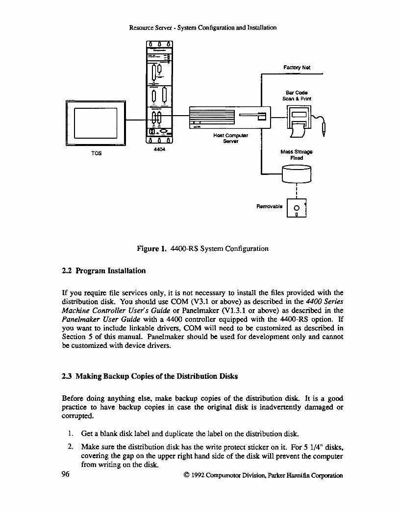
D TCS
Resource Server - System Configuration and Installation
4404
Host Computer Server
a
Figure 1. 4400-RS System Configuration
2.2 Program Installation
Factory Net
Bar Code Scan & Print
Mass Storage Fixed
If you require file services only, it is not necessary to install the files provided with the distribution disk. You should use COM (V3.1 or above) as described in the 4400 Series Machine Controller Users Guide or Panelmaker (V1.3.1 or above) as described in the Panelmaker User Guide with a 4400 controller equipped with the 44OO-RS option. If you want to include linkable drivers, COM will need to be customized as described in Section 5 of this manual. Panelmaker should be used for development only and cannot be customized with device drivers.
2.3 Making Backup Copies of the Distribution Disks
Before doing anything else, make backup copies of the distribution disk. It is a good practice to have backup copies in case the original disk is inadvertently damaged or corrupted.
1. Get a blank disk label and duplicate the label on the distribution disk.
2. Make sure the distribution disk has the write protect sticker on it. For 5 1/4" disks, covering the gap on the upper right hand side of the disk will prevent the computer from writing on the disk.
96 © 1992 Compumotor Division, Parker Hannifin Corporation

Resource Server - System Configuration and Installation
3. If your computer has only a single 5 1/4" floppy disk drive, you can backup the distribution disk by going through the following steps (Note that the messages displayed may be slightly different, depending on the version of the DOS operating system you are using).
At the DOS prompt type the following command. Note that <ENTER> refers to pressing the Enter key (this key is also called Return on some keyboards).
diskcopy a: a: <ENTER>
DOS prints
Insert SOURCE diskette in Drive A:
Press any key when ready ...
Put the distribution disk in the A: drive and type any character. DOS reads the disk and displays
Copying 40 tracks 9 sectors/track, 2 Side(s)
Insert TARGET Diskette in Drive A:
Press any key when ready ...
Put the blank disk in the A: drive and type any character. DOS copies what it had read onto the blank diskette and displays
Formatting while copying
Insert SOURCE Diskette in Drive A:
Press any key when ready ...
Put the distribution disk in Drive A: and press a key so that DOS can finish reading the disk. When it has completed reading it displays
Insert TARGET Diskette in Drive A:
Press any key when ready ...
DOS copies the rest of the distribution disk to the backup copy. When it is done, it asks you if you want to copy another diskette. Remove the disk from the drive and put on its label.
4. If your computer has two 5 1/4" floppy disk drives, it is easier to make backup disks than if you have a single drive only.
Type the following at the DOS prompt:
diskcopy a: a: <ENTER>
© 1992 Compumotor Division, Parker Hannifin Corporation 97
98
Resource Server - System Configuration and Installation
DOS prints
Insert SOURCE Diskette in Drive A:
Insert TARGET Diskette in Drive A:
Press any key when ready ...
Put the distribution disk in drive A: and the blank disk in drive B:. When DOS completes the copying, it asks you whether you want to copy another disk. Remove the both disks from the drives, and put on the label for the backup disk.
© 1992 Compumotor Division, Parker Hannifin Corporation

Resource Server - Tutorial
3. Tutorial for the Resource Server
This tutorial will provide examples of using the Resource Server. This section will explain the basic concepts of 4400-RS and what the 4400 can accomplish with 4400-RS. It will guide you through the various aspects of 4400-RS - from the basic commands to the development of a system using the commands. Sections of the tutorial will provide examples of usage of the Resource Server. The example programs are also available in the rstutor.p file provided with the distribution diskette.
This tutorial assumes some knowledge of the operation of the 4400 Machine Controller and the ffiM-AT or compatible computers, that Resource Server has been installed and necessary hardware is in place. For additional infonnation on the operation of the 4400 Servo Controller, refer to the 4400 Series Servo Controller User's Guide.
3.1 Development Environment
COM provides a complete development environment for Parasol-II programs, including ability to edit files, download files to the 4400, upload data from the 4400, log an interactive session, save gains, and store to the non-volatile memory. The same PC program is also used during runtime. However, it is to be noted that the runtime mode for COM is very different from conventional PC programs.
COM operates on a PC running the DOS operating system. In this architecture, the 4400 has control of the system, and the PC is essentially a disk drive for the 4400. The 4400 issues commands to the PC server, and the server responds to these requests. It is important to note the server is always present to service any requests issued by the 4400, but the server never initiates any data transactions by itself. DOS is a single tasking operating system, which means only one program can be run at a time. With the COM running on the PC, it is the only task that can run.
During development, the system has two distinct modes. With the 4400 at the Parasol-II prompt, there is no file activity going on. In this mode, COM is in control of the system. The user can use the development support features of COM, that is, use the function keys to invoke an editor or download files to the 4400. When the software is being tested, the 4400 is issuing commands to the PC, and the server is servicing these commands. Now the 4400 is controlling the system. At this point, the user should not use the function keys on the PC. A typical configuration during development is shown in Fig. 2.
© 1992 Compumotor Division, Parker Hannifin Corporation 99

Resource Server - Tutorial
Q Q Q -==-- ::1 ~-v
D _--v-
~ ~ ... • •
D ,.,,., Data Unk
D '!'! -,-
lm ... 9. 1'iin"1: "~,:&!Iii!!IFII1 6 8 6
TCS 4400 HOST COMPUTER
Figure 2. Development Configuration
During runtime, the program must be running on the PC at all times since it is servicing requests from the 4400. That implies no other program can be run on the PC. The special keystrokes, i.e, the function keys and Alt key combinations should never be used during runtime. In fact, during actual machine operation, it is best to think of the PC as not having a keyboard or CRT attached. A typical runtime configuration is shown in Fig. 3.
D TCS
100
-,-
4404
Host Computer Server
Figure 3. Runtime Configuration
D
Factory Net
Bar Code Scan & Print
Mass Storage Fixed
I I
RomovaIH. GJ
© 1992 Compumotor Division, Parker Hannifin Corporation

Resource Server - Tutorial
3.2 Basic Concepts
Two of the basic terms used in this manual are files and devices. A file allows data storage. The loadfile .nvrn file is an example of a non-volatile file. A device is a piece of hardware or combination of hardware and software that allows data exchange. Devices can be accessed by special software called device drivers. Examples of devices are the com2: serial communication port on the 4400 and a bar code scanner connected to the PC. The 4400 supports a number of devices: the serial ports, coml: and com2 :, and the parallel port, pi:. All these devices are internal to the 4400, and the drivers for these devices are provided with the 4400.
With the 4400-RS, the 44OO's control capability is expanded to include DOS files and external devices on the PC. By default, the 4400 assumes that the PC is not connected, and that the drivers for the server are not active. The user must explicitly activate the drivers by using the Stty command. With Resource Server activated, the user has access to the DOS file system as well as devices connected to the PC. Drivers for accessing the PC file system are incorporated in COM and Panelmaker. Drivers for any other devices connected to the PC must be developed by the user. In this manual, the term device will be used to refer to devices that are connected to the PC, and can be accessed from the 4400 using the Resource Server. Files and devices are treated very similarly by the Parasol-II program running on the 4400. Most concepts that apply to a file apply to a device as well, and in general the termfile will be used for both. The term device will be used when talking about operations specific to devices only.
There are two basic operations that you can perform on a file; read and write. However, before you can read from or write to a file, the file must be prepared for the operation. This is done by opening the file. A file must be opened before anything else can be done with the file. This step prepares the file for future read or write operations. For DOS files, the file can be opened either for reading or for writing, but not for both at the same time.
Read and write operations perform data exchange with the file or device. The 4400 handles ASCII data only. Data to be written to files is generated on the 4400 as ASCII strings. Files to be read contain ASCII data, with the data separated into lines. Lines are terminated with a newline character. If you create the file with an ASCII editor, such as SEE, hitting the Enter key puts a newline character in the file. A read operation assumes that there is data available from the file or device. Each read operation reads the next line from the file. When there is no more data available, the file pointer is said to be at the end of file.
Keeping a file open takes up system resources on the PC. Every file that is opened must have memory allocated to it for buffering data. So, after reading from or writing to a file is complete, it should be closed. This releases the memory back to the system. Note that data written to a DOS file is not valid until the file is closed.
© 1992 Compumotor Division, Parker Hannifin Corporation 101

Resource Server - Tutorial
3.3 Device Handling
Devices are hardware connected to the PC that can be accessed by custom software. Unlike the DOS files, the operating system on the PC does not know about them. These are completely controlled by the device drivers written by the user. To the Parasol-II software, files and devices look very similar, but usually extra handling is required for devices. The handling depends on the device drivers written by the user. This section does not discuss techniques for writing device drivers. It is covered later in this manual.
Note that device support cannot be added to Panelmaker. The test mode in Panelmaker provides the file service capabilities, but device drivers cannot be linked into Panelmaker. Code that interacts with the devices must be debugged while running your customized COM.
One major difference between DOS files and devices is that most devices require an extra step before the device can be opened for reading or writing - initialization. Most devices need to be initialized after power up. This is done with the Finit command. Note that there is no restriction on when the Finit command can be used. This depends on the device driver. Also, since an initialization string is passed to device driver, a variety of functions can be perfonned by the command.
The Finit command is called with two string arguments. The first argument is the name of the device. The second argument is passed to the device driver. The device driver parses the string and initializes the device. After initializing, the device driver returns a number to indicate the status of the operation. This number is returned to the top of stack by the Finit command.
Example 1 - The distribution disk for 44oo-RS contains a driver for the PC serial communication ports. The port must first be initialized to specify the communication port and to set up the data format. Assume the device driver was linked in with the name serial. Initialize the driver to use the COM2: port on the PC and to set the data fonnat to 9600 baud, no parity, 8 data bits per word and 1 stop bit, and display the return value after initialization.
p2> -serial" "2 9600 0 8 1- Finit 1 Print p2> 0
Unlike DOS files, devices can be opened for reading only, writing only, or for both reading and writing. The device driver must be able to support the selected mode.
3.4 Blocking and Non-blocking 110
For the purpose of reading, files can be broadly classified into two categories: stream files and character devices. For stream files, for example a DOS file, the end of file is a welldefined condition. Once the end of file condition is encountered, no new data can be expected in the future. A read operation on a stream file either returns data from the file, or returns an end of file condition. For a character device, like a communication port, new data can arrive at any instant. Having no data available currently does not imply
102 © 1992 Compumotor Division, Parker Hannifin Corporation
Resource Server - Tutorial
data will not be available for reading in the future. A read operation for a character device can wait until data becomes available, or it can return immediately, with data if it is available, or indicate that no data is available. The first mode, where the read operation waits until data becomes available, is called the blocking mode of operation. The second mode, where the operation does not wait for data to become available, is called the non-blocking mode of operation. Only blocking mode can be used for DOS files. We recommend using non-blocking mode for devices, although blocking mode can be used too.
Like the read operation, a write operation can be blocking or non-blocking. However, the behavior of the blocking and non-blocking write operations are defined differently from the read. The write command on the 4400 and the write operation on the PC server are not synchronous. The data is first buffered in an output buffer on the 4400. A write operation succeeds if there is enough space in this output buffer to contain the entire data. A blocking write operation returns only after the entire string is buffered. If the buffer is full, it will wait until there is room available. A non-blocking write buffers the entire data if space is available. Otherwise, it returns immediately without entering any data in the output queue. The blocking or non-blocking mode can be set at the time of opening the device, and this mode applies to both read and write operations.
Note that while the behavior in non-blocking mode is usually more desirable, it also takes more software to support non-blocking mode I/O.
3.5 File Services
Files are opened with the Fopen command. Two parameters specify the mode of operation at the time of opening the file; the data exchange mode and the file I/O mode. The data exchange mode specifies whether the file should be opened for read only, write only, or read and write. The file I/O mode specifies whether the file accesses are going to be blocking or non-blocking.
When the Fopen command is executed on the 4400, it commands the program on the PC to open the specified file. The system must keep track of all open files. This is done by associating a unique number with each open file. This number is called the file handle for that specific file. This number is returned by the Fopen command. Once a file has been opened, all further references to the file must be made using this file handle. This file handle is valid as long as the file is open. It can be assigned to a different file that is opened after the previous file associated with the file handle is closed.
Example 2 - Copy the file read. t s t from the distribution disk to your hard disk. Open a diskfile wr it e . t s t for write and the file read. t s t for read and print the file handles assigned to these files. Open both files for blocking I/O.
p2> "write.tst" 2 0 Fopen 1 Print 1 p2> "read.tstA 1 0 Fopen 1 Print 2
© 1992 Compumotor Division, Parker Hannifin Corporation 103

Resource Server - Tutorial
The Fread command is used for reading files. It requires one argument, the file handle of the file to read from. Fread issues a read command to the server on the PC. The program on the PC reads the next line from the file and returns the data to the 4400. Normally the file would be read up to the next newline character. However, Parasol-II supports reading strings up to 200 characters long. So, if the line is more than 200 characters long, the first 200 hundred characters are returned. The remaining characters are returned by subsequent read commands. It is strongly recommended that you use data formats such that line lengths are fairly short.
The Fread returns the length of the string read after stripping the newline character from the line. If there is no more data to be read, then it returns -1. If any data is read, it leaves the string on the stack.
Example 3 - Read the first line of the file opened for read in the previous example. Print the number returned by the Fread command. If the number is a positive number, print the string returned to the stack.
p2> 2 Fread 1 Print p2> 26 p2> Pmsg p2> Welcome to Resource Server
For files opened in the blocking mode, issuing an Fread command would stop further processing on the 4400 until the command execution completes. In some situations, this may not be desirable. If the read. t s t file was stored on a floppy diskette, it could take several seconds for the command to complete, depending on the floppy disk access speed. It would be preferable if the execution time for the Fread command could be reduced. The command Flinerdy can be used under these circumstances. This command is very similar to a non-blocking read, but can be used for files that must be read in blocking mode. This command initiates a read on the PC server, but does not wait for the task to complete and returns immediately. It returns 0 to the stack until the read is complete, and the PC server has transferred the data read to the 4400. At this point, it returns 1 to the stack. After Flinerdy returns 1, the Fread command can be used to read the data from the buffer.
104
Example 4 - Define a function to read a line from the input buffer of a file opened in the blocking mode. The file handle is stored in the variable . fh. If a line is already in the buffer, the function reads the line. The length of the string is stored in the variable . 1 en and the string is stored in the variable . s t r. The routine returns a 1 if a line is read, 0 if no data is available.
Define getline
.fh Flinerdy If true
.fh Fread @.len @.str 1
Else o
Endif
© 1992 Compumotor Division, Parker Hannifin Corporation

R~wxeSeNer-Turoriru
End
Data is written to a file using the Fwrite command. The write operation is not synchronous. In the 4400, all communication data is first buffered before being transmitted. Unlike the Fread command, the Fwrite does not need to get any data back from the server on the PC. It simply puts the data in the output buffer, and returns. For this, however, there must be enough space in the output buffer for the string to be written. The data is transmitted to the server a short time later, and the server takes care of writing the data to the file. The actual write operation on the PC happens after the Fwrite command has returned. Once again, it is recommended that the string lengths are kept short.
Example 5 - In Example 2, the file write. tst was opened for writing. Now write a line of Parasol-II commands to the file.
p2> "123 1 Print\n" 1 Fwrite 1 Print o
It is obvious that if an error occurs in the write operation, for example, the disk fills up, Fwrite will not be able to report the error condition. If the disk fills up and the data does not get logged, it is important to get the infonnation across to the user. So at the time of closing the file, checks are made for previous write errors. If a write error was logged, the error is reported at the time of closing the file.
Files are closed with the Fclose command. This command releases the memory allocated to the file on the PC and on the 4400, and frees up the file handle for possible use in the future. If an error occurs at the time of closing the file, this command reports it.
Example 6 - Define a program that would open the file read. t s t for reading, read the lines and print them to the console.
Define printfile
i open the file for reading "read.tst" 1 0 Fopen @.fh ; check if the file open succeeded .fh 0 > If true
1 @.f_loop
Repeat ; read a line from the file .fh Fread 0 >= If true
Else
; print the line read Prnsg
exit loop o @.f_loop
Endif .f_loop
© 1992 Compumotor Division, Parker Hannifin Corporation 105

End
Else
Resource Server - Tutorial
Endrpt i close the file .fh Fclose Drop
RFailed to open file. N Pmsg Endif
3.6 Additional Features
While the Fread and Fwrite commands allow reading from and writing to files, they cannot provide any feedback on the I/O operation status. For example, the Fwrite command returns after buffering the data in the local buffer on the 4400. The actual write operation happens later, after the data has been queued to the appropriate device driver on the server PC. Errors may occur at this stage. For example, the disk may fill up and there may be no more space left to store the data. The server reports previous write errors at the time when closing a file. When logging real-time data over a long period of time, this is not satisfactory. It is necessary to periodically check the status of I/O to minimize the loss of data. The Ferror command lets the user check on the status of the operation, and if an error occurs, determine the cause of the error.
106
Example 7 - Define a program for logging real-time data to a disk file. The data is passed to the routine on the stack. It writes the data to the file in the blocking mode. The file handle is stored in the variable . fh. Periodically, it checks the file write I/O status for errors. The frequency of checks is defined by the variable . chkfreq. If no errors are detected, this routine returns 1. Otherwise, it returns O. This type of periodic check is useful when real-time data is logged over an extended period of time.
Define logdata
i write the string to the file .fh Fwrite @.retcode .retcode 0 == If true
i increment line count .linecount 1 + @.linecount .linecount .chkfreq == If true
reset line counter o @.linecount i check file write I/O status 1 .fh Ferror @.errcode .errcode 0 == If true
1
© 1992 Compumotor Division, Parker Hannifin Corporation
End
Else
Else
o Endif
Resource Server - Tutorial
error occured
return success 1
Endif Else
o Endif
write failed
Files can have different modes of I/O operations. For example, both blocking and nonblocking modes may be supported for some files. It often becomes necessary to set or change the mode. A device can be opened for blocking mode I/O, and later it may become necessary to change it to non-blocking mode. This is done with the Fmode command. It is not limited to switching between blocking and non-blocking modes only. A variety of I/O mode control functions can be performed with this command.
Example 8 - Sometimes a 4400 may be used for loading Parasol-II programs to a second 4400. The program is stored in a disk file. Typical Parasol-II source files contain a substantial amount of comments. Stripping the comments at the time of reading the file reduces the load time significantly. Define a function to open a disk file for reading and to set the read mode to strip comments. The filename is passed to the function on the stack. It returns the file handle if it opens the file successfully, o if it fails.
Define pfopen
i open file for read 1 0 Fopen @.fh .fh 0 > If true
Else
i set mode to strip Parasol-II comments 4 .fh Fmode 0 --If true
Else
i return file handle .fh @.ret_code
; failed to set mode .fh Fclose Drop o @.ret_code
Endif
i failed to open file o @.ret_code
Endif
© 1992 Compumotor Division. Parker Hannifin Corporation 107

End
Resource Server - Tutorial
; leave return code on stack . ret_code
A blocking write operation waits only until it can buffer the data in the local output buffer on the 4400. A blocking read operation must go to the device driver to get the data. Very heavy file activity can slow these operations down significantly, which can hamper time critical activities. An error condition can prevent the operation from completing. It is highly undesirable for the 4400 Machine Controller to hang up due to a failure in the peripherals. The Ftimeout command allows you to set the time limit for these operations for which the 4400 may wait for the command to complete. Note that the timeout values must be set with caution. This is essentially a mechanism for recovery from error conditions. You should not design your system to do a blocking read on a slow device at a time when time critical machine activities may be happening. The timeout feature should not be viewed as a means of getting around bad design.
Example 9 - Set the timeout for file operations that are not file specific to 10 seconds.
p2> 10000 -1 Ftirneout 1 Print o
A source of this problem is the server not being connected to the 4400, and typically happens at the time of starting up the system after a power down. It is a good idea to check if the server is responding at the time of startup using the Fstat command. File services should be attempted only after ensuring the server is connected.
Example 10 - Check if your COM has file system support.
p2> Fstat 1 Print o
It is usually not sufficient to recognize when a major problem occurs, for example, the communication link between the 4400 and the server breaks. A well-designed system should also be able to recover from the condition after the cause of the problem has been taken care of. When a problem like this occurs, the server and the 4400 lose synchronization. The Freset command allows the server and the 4400 to re-establish synchronization under software control without having to power down the system.
108 © 1992 Compumotor Division, Parker Hannifin Corporation

Resource Server - Tutorial
3.7 Examples
1. This is an example program that would allow the 4400 and the PC program to establish synchronization after powering up the system. This program would allow automatic startup after a power down.
i*+*************************************************** **** Example program to start up Resource Server. TYpical usage of this program will be to start up a system after
i power up without operator intervention. This program i must be stored in the non-volatile memory in the 4400.
This routine assumes it will be run at time of starting the system up, and that the system cannot be run without the server.
This routine first checks if the server is responding. If the server does not respond, then the routine tries to reset the server. After the reset succeeds, it makes sure the server is connected before returning .
. *-******************************************************* ,
Define init_rs
End
enable Resource Server mode on 4400 1 26 Stty
check if the server is responding Fstat 0 != If true
Repeat Repeat
i try to re-initialize the server 1 Freset 0 !=
Endrpt ; make sure the server is initialized Fstat 0 !=
Endrpt Endif
2. This example shows a program to load part data stored in the form of a matrix of data points to a matrix defined in the 4400.
;*+******************************************************* ; Example program to load part data from a PC file and
© 1992 Compumotor Division, Parker Hannifin Corporation 109

110
Resource Server - Tutorial
store the data in data table. This program assumes that the server is connected to the 4400, and the link has been tested prior to running this routine. The part data is stored as a matrix with 3 columns per row. The number of rows in the file is not fixed. It is assumed that the data table defined in the 4400 has enough rows to contain the part data.
i The name of the file containing the part data is passed i to the program on the stack. This program stores the
data in the data table and sets the variable R.nrowsR to i indicate the number of rows used by the part data. It
returns 1 if it succeeds, 0 if it fails to read the part . . *-******************************************************* ,
Define load-part
; store the name of the data file @.fnarne ; open the file for read .fname 1 0 Fopen @.fh .fh 0 > If true
reset row counter o @.nrows
set repeat flag 1 @.f_rpt Repeat
; read next line .fh Fread 0 >= If true
; store the string returned @.str ; convert to numbers .str Stof @.ncols .ncols 3 == If true
; increment row pointer .nrows 1 + @.nrows ; store data .nrows .m-part_data Msetrow
Else ; file read error - clear stack Repeat
Drop .ncols 1 - @.ncols .ncols
© 1992 Compumotor Division, Parker Hannifin Corporation

End
Else
Resource Server - Tutorial
Endrpt set error return code
o @.ret_code reset repeat flag
o @.f_rpt Endif
; check for file read errors o .fh Ferror -1 --If true
Else
file read successfully 1 @.ret_code
file read error o @.ret_code
Endif
reset repeat flag o @.f_rpt
Endif
; close data file .fh Fclose Drop
Else failed to open file
o @.ret_code Endif
; put the return code on stack . ret_code
© 1992 Compumotor Division, Parker Hannifin Corporation 111
Resource Server - Command Summary
4. Resource Server Command Summary
The 4400 Resource Server provides a means of accessing disk files and devices on the host computer from the 4400 Servo Controller. The following section describes additional Parasol-II commands that are included in the 4400 Machine Controller when the Resource Server option is specified.
The following commands are described:
Fclose
Fcopy
Ferror
Finit
Fstat
Flinerdy
Fmode
Fopen
Fsys
Fread
Freset
Ftimeout
Fwrite
Close an open 4400 file.
Copy aParasol-II source file.
Check file I/O error status.
Initialize a device on the host system.
Check if the host computer is responding.
Check a file buffer for a complete line.
Change the I/O control mode for an open file.
Open a 4400 file.
Issue a command to the host computer's operating system.
Read a line from an open 4400 file.
Reset the Resource Server to a known state.
Specify the timeout for a blocking operation.
Write a string to an open 4400 file.
The commands, Fclose, Ferror, Flinerdy, Fmode, Fopen, Fread and Fwrite are also available with the standard 4400 Servo Controller. However, with the Resource Server option, these commands are enhanced to include extra functionality.
112 © 1992 Compumotor Division, Parker Hannifin Corporation
Resource Server - Command Summary Fclose
NAME:
Fclose
FUNCfION:
Fclose is the command used to close an open file. For external devices connected to the host computer, Fclose will result in a call to the close routine of the device driver. A typical usage is
fh Fclose
where fh is the file handle for the file to be closed.
ARGUMENTS:
Fclose requires one argument; the file handle for the file to be closed.
RETURNS:
Fclose returns a value to the top of stack. This value is 0 if the file close succeeds. Otherwise, the return value is negative. For files opened for write, Fclose will return an error if a previous write generated an error, and the I/O status was not checked after the error occurred. An error is returned if the file is not open. The Fclose error return codes are:
-1 Reserved. -2 File not open. -4 File write overflow (non-volatile memory files only). -6 File write error (disk and non-volatile memory files only). -10 Command timed out. -11 Error detected. Server must be reset. -12 Server command queue full. Command could not be issued.
Other error codes are returned by the specific device driver.
EXAMPLE:
Define a function to close the file with the handle stored in the variable fh2. If the file closes successfully, return 1. If the file close fails, print a message indicating failure and return O.
Define fcls
.fh2 Fclose @.stat
.stat 0 --If true
Else 1
"Failed to close fileR Prnsg .stat -11 ==
© 1992 Compumotor Division, Parker Hannifin Corporation 113

Fclose Resource Server - Command Summary
If true "Server needs to be reset" Prnsg
Endif o
Endif End
SEE ALSO:
Fopen
114 © 1992 Compumotor Division, Parker Hannifin Corporation

Resource Server - Command Summary Fcopy
NAME:
Fcopy
FUNCfION:
Fcopy is the command used to copy Parasol-II source files. Fcopy will copy a single source file or a set of files to the target file. If the source file has a . de f extension, it is treated as a definition file containing the names of Parasol-II source files. Otherwise it is treated as a single Parasol-II source file. The Fcopy command strips Parasol-II comments, removes redundant white spaces and produces a single source file minimized for size. A typical usage is
source target Fcopy
where source is the name of the source file, and target is the destination file name.
ARGUMENTS:
Fcopy requires two arguments; the name of the source file and the name of the destination file.
RETURNS:
Fcopy does not have any return value.
EXAMPLE:
Copy a set of Parasol-II source files named in the file nonvol. def to the nonvolatile memory file, loadfile. nvm.
p2> "nonvol.def n "loadfile.nvm" Fcopy
NOTES:
Nested definition files are not supported by the Fcopy command.
© 1992 Compumotor Division, Parker Hanni fin Corporation 115

Ferror Resource Server - Command Summary
NAME:
Ferror
FUNCfION:
Ferror is the command used to check file I/O error status. This command is blocking or non-blocking depending on the type of file and whether it is checking for read or write errors. For non-volatile memory files and communication ports I/O status checks and for read status checks of all files, this function is non-blocking. Write error status checks of devices and disk files are blocking. This function returns the last I/O error status for the specified mode and file. The error logs are cleared when they are read. A typical usage is
mode fh Ferror
where mode is the read or write I/O mode, and fh is the file handle for the file whose error status is to be checked.
ARGUMENTS:
Ferror requires two arguments; the I/O mode and the handle for the required file. The I/O mode can be either read or write.
o read error status 1 write error status
RETURNS:
Ferror returns the I/O status code of the last Fread operation for read error checks. For write error checks, it returns the error code for the last write error to have occurred. It returns an error if the file is not open, or if the file is not opened for the specified I/O access mode. The Ferror error return codes are:
-1 End-of-file condition for disk and non-volatile memory files. -2 File not open. -3 File not open for specified I/O mode. -4 File write past partition (non-volatile memory files only). -6 File write error (disk and non-volatile memory files). -10 Command timed out. -11 Error detected. Server must be reset. -12 Server command queue full. Command could not be issued.
EXAMPLE:
116
Define a function to close a disk file opened for reading in the blocking I/O mode when the end of file is received from the host. The handle for the file is stored in the variable fh2.
Define chkfile i-------------
© 1992 Compumotor Division, Parker Hannifin Corporation

End
Resource Server - Command Summary
.fh2 Fread -1 == If true
; read error o .fh2 Ferror -1 == If true
; end-of-file - close file .fh2 Fclose @.fh2
Endif Endif
SEE ALSO:
Freset, Fclose, Fread, Fwrite
© 1992 Compumotor Division, Parker Hannifin Corporation
Ferror
117
Finit Resource Server - Command Summary
NAME:
Finit
FUNCTION:
Finit is the command used to initialize devices connected to the host computer. Finit results in a call to the initialize routine of the device driver on the host. A typical usage is
devname string Finit
where devname is the name of the device to be initialized, and string is the argument string to be passed to the device driver.
ARGUMENTS:
Finit requires two arguments; the name of the device to be initialized and the argument string to be passed to the device driver. The device name must be the same as the name specified at the time of compiling the device driver.
RETURNS:
Finit returns an integer to the top of stack indicating the status of the initialize call. The Parasol-II error return codes are:
-1 Reserved. -2 Device name not found. -10 Command timed out. -11 Error detected. Server must be reset. -12 Server command queue full. Command could not be issued.
Otherwise, the return value is the same as the number returned by the device driver on the host. The general convention is 0 or a positive number to indicate success, a negative number to indicate failure.
EXAMPLE:
118
Define a function to initialize the device named scope. The device driver does not need any other argument. It returns a 0 if it initialized the device successfully, -3 if hardware is not installed, or -4 if the hardware failed. If the device initialization fails, print a message indicating the type of error.
Define scopeinit
·scope" nn Finit @.stat .stat -2 == If true
"Device name not found" Prnsg Else
.stat -3 ==
© 1992 Compumotor Division, Parker Hannifin Corporation

Resource Server - Command Summary Finit
If true "Hardware not installed" Pmsg
Else .stat -4 == If true
nInitialization failure" Pmsg Else
.stat -10 -If true
Fstat 0 == If true
"Initialization timed out" Pmsg Else
End
NOTES:
Else
"Server error detected" Pmsg Endif
"Server error detected n Pmsg Endif
Endif Endif
Endif
The Finit command is normally used to initialize hardware before opening the device file. However the actual operation performed by the command depends on the specific device and driver. The driver would also determine if the command can be issued with the file open or not.
Special initialization is not required for disk files or non-volatile memory files.
SEE ALSO:
Ftimeout, Fstat, Freset, Fopen
© 1992 Compumotor Division, Parker Hannifin Corporation 119
Flinerdy Resource Server - Command Summary
NAME:
Flinerdy
FUNCflON:
Flinerdy is the command used to check a file buffer for a complete line. This command is always non-blocking. A typical usage is
fh Flinerdy
where fh is the file handle for the file whose buffer is to be checked.
ARGUMENTS:
Flinerdy requires one argument; the handle for the file's buffer to check.
RETURNS:
Flinerdy returns a 1 to the top of stack if the file's input buffer contains a complete line. If a complete line is not available, Flinerdy leaves a 0 on the stack. Otherwise, if an error occurs, it leaves a negative number on the stack. The Flinerdy return codes are:
1 file contains a complete line. o file does not contain a complete line. -1 reserved. -2 file not open, -3 file opened for write only.
EXAMPLE:
120
Define a function to check the input buffer of a file opened in the blocking I/O mode for a line. The file handle is stored in the variable fh2. If a line exists, it reads and stores it in the variable s t r. The routine returns 1 if a string was read, 0 if a line is not available. Otherwise, if a read error is detected, it returns -1.
Define get line
.fh2 Flinerdy If true
Else
.fh2 Fread @.len @.str 1
o .fh2 Ferror 0 < If true
-1 Else
o Endif
Endif
© 1992 Compumotor Division, Parker Hannifin Corporation

Resource Server - Command Summary Flinerdy
End
NOTES:
The Flinerdy command is normally used before a blocking read command for buffers that get filled asynchronously. The Ferror command should be used in conjunction with the Flinerdy command to check for read errors to make effective use of the command.
SEE ALSO:
Fread
© 1992 Compumotor Division, Parker Hannifin Corporation 121

Fmode Resource Server - Command Summary
NAME:
Fmode
FUNCI10N:
Fmode is the command used to change I/O control mode for a file that is already open. Fmode will usually result in a call to the I/O control routine of the device driver on the host. A typical usage is
iocommand fh Fmode
where iocommand is the I/O control command to be executed, and fh is the handle for the file whose I/O control mode is to be modified.
ARGUMENTS:
Fmode requires two arguments; the I/O control command and the handle for the file whose I/O mode is to be modified. The I/O control commands 0 to 31 are reserved for the 4400's internal use. The numbers from 32 to 63 are used by specific device drivers for specific I/O control functions. Drivers for external devices connected to the host computer can use these to I/O control specific to these devices. The I/O control commands currently supported by the 4400 are:
o set subsequent I/O mode to blocking 1 set subsequent I/O mode to non-blocking 2 enable interpretation of escape sequences for output 3 disable interpretation of escape sequences for output 4 strip Parasol-II comments while reading (disk file only) 5 disable stripping of Parasol-II comments (disk file only) 6 enable echoing of input (communication ports only) 7 disable echoing of input (communication ports only)
A few additional features for the parallel port are also available. These are:
32 configure port for initiator mode 33 configure port for target mode 34 enable character oriented read 35 enable line oriented read
RETURNS:
122
Fmode returns a value to the top of stack indicating the status of the command. The Fmode return codes are:
o -1 -2 -10 -11 -12
I/O control command successful. Illegal file handle or I/O mode not supported. File not open. Command timed out. Error detected. Server must be reset. Server command queue full. Command could not be issued.
© 1992 Compumotor Division, Parker Hanni fin Corporation

Resource Server - Command Summary Fmode
Other error return codes may be returned by specific device drivers.
EXAMPLE:
Define a function to open a disk file for write and to set the output mode to disable interpretation of escape sequences. It returns the file handle if it succeeded in opening the file and setting the I/O control mode. Otherwise, it returns -1.
Define pfopen i------------
End
NOTES:
; open the output file -ternp.p- 2 0 Fopen @.fh .fh 0 > If true
; disable interpretation of escape sequences 3 .fh Frnode 0 == If true
Else . fh
; close the file .fh Fclose Drop -1
Endif Else
-1 Endif
The Fmode command can be used only after the file has been opened. With the exception of the output escape sequence processing control command, the I/O control commands reserved by the 4400 are interpreted by the 4400 as well as by the device drivers. These commands have to be supported by the specific device drivers in order to utilize them. The other I/O control commands are not interpreted by the 4400.
SEE ALSO:
Finit, Fopen
© 1992 Compumotor Division, Parker Hanni fin Corporation 123

Fopen Resource Server - Command Summary
NAME:
Fopen
FUNCTION:
Fopen is the command used to open a file for reading or writing under the 4400 file system. If a device file on the host is opened, Fopen will result in a call to the open routine of the device driver. A typical usage is
"filename" openmode iomode Fopen
where filename is the name of the file to be opened, openmode is the mode of opening the file, and iomode is the mode of I/O operations on the file. The file can be a non-volatile memory file, a disk file, a device or a 4400 communication port. For device files, the file name has to match the name specified when linking in the device driver. The ports that can be opened are coml:, com2: and pi:. The port names are case sensitive.
A brief summary of the mode options is given below:
File Open Mode Options
The open mode values are interpreted as follows:
1 Read only 2 Write only 4 Read and write (truncate) 10 Append (write only) 12 Append (read and write)
I/O Mode Options
This parameter specifies blocking or non-blocking I/O mode. The I/O mode is defined as blocking if a read or write waits for the operation to complete before returning. A blocking read waits until a line is available or an error occurs. A blocking write waits until the data can be put in the output buffer. A non-blocking read returns a line if one is available. A non-blocking write puts the data in the output buffer if there is enough space to buffer the data. Otherwise, the nonblocking commands return immediately with the appropriate return code. The I/O mode parameter is ignored for non-volatile memory files and disk files. The I/O mode for these files is always set to blocking mode.
o Blocking file I/O. 1 Non-blocking file I/O.
ARGUMENTS:
Fopen requires three arguments; the name of the file to be opened, the open mode and the I/O mode.
124 © 1992 Compumotor Division, Parker Hannifin Corporation
Resource Server - Command Summary Fopen
RETURNS:
Fopen returns a value to the top of the stack. This number is negative if the file open fails. Otherwise, the return value is a positive number (file handle) which is used to identify the opened file. The Fopen error return codes are:
-1 File table full. Maximum number of files are open. -2 File not found (for disk and non-volatile memory files). -3 Invalid access mode. -4 File already open (for devices and non-volatile memory files). -5 Device not installed (for non-volatile memory only). -6 File open error (for non-volatile memory only). -10 Command timed out. -11 Error detected. Server must be reset. -12 Server command queue full. Command could not be issued.
Other error codes may be returned by the device driver. All further references to the file are made using the file handle.
EXAMPLE:
Define a function to open the device file scope for read and write. File I/O is non-blocking. The routine stores the return value in the variable fh2. If the file is opened successfully, it returns 1. If the file open fails, it prints a message indicating failure and returns O.
Define scopeopen
End
NOTES:
"scope" 4 1 Fopen @.fh2 .fh2 0 <
If true "Failed to open file" Pmsg .fh2 -11 == If true
"Server needs to be reset" Pmsg Endif o
Else 1
Endif
For files other than disk files and non-volatile memory files, the Fopen command is normally used after the hardware has been initialized. For disk files and nonvolatile memory files, no hardware initialization is necessary. Certain file I/O modes can be modified while the file is open using the Fmode command if this is supported by the device driver. The file access mode cannot be changed while the
© 1992 Compumotor Division. Parker Hannifin Corporation 125

Fopen Resource Server - Command Summary
file is open. The file has be closed and reopened in the desired mode.
The communication ports require special attention. The port to which the 4400 sends the Parasol-II prompt is called the active communication link. Only the ports that are not the active communication link can be opened. While a port is open, it cannot become the active communication link.
SEE ALSO:
Ftimeout, Fstat, Freset, Finit, Fclose
126 © 1992 Compumotor Division. Parker Hannifin Corporation

Resource Server - Command Summary Fread
NAME:
Fread
FUNCI10N:
Fread is the command used to read from a file that has been opened. The Fread command can be blocking or non-blocking depending on the file I/O mode specified when the file was opened. In the blocking mode, it waits until it gets a line tenninated with a newline ('\n') or until a timeout occurs before it returns. In the non-blocking mode, it returns immediately. The newline character is stripped off the line returned. A typical usage is
fh Fread
where fh is the handle for the file to be read.
ARGUMENTS:
Fread requires one argument; the file handle for the file to be read.
RETURNS:
Fread returns the number of characters in the string that was read followed by the text string. If the read is successful, this number is a non-negative number. Otherwise, it returns a negative number indicating an error. If an error occurs, it does not return a string on the stack. The Fread error return codes are as follows:
-1 End-of-file. No data returned. -2 File not open. -3 File opened for write only.
EXAMPLE:
Define a function to read from a disk file whose file handle is stored in the variable fh2. The routine returns 1 if Fread returns a string, and stores the string in the variable str. If end-of-file is encountered, it closes the file and returns O. If a read error occurs, it returns -1.
Define fileread
.fh2 Fread @.stat
.stat -1 == If true
Else
; end of file .fh2 Fclose @.fh2 o
.stat 0 >= If true
; store the string returned
© 1992 Compumotor Division, Parker Hanni fin Corporation 127
Fread Resource Server - Command Summary
End
Else
@.str 1
"Failed to read file" Pmsg -1
Endif Endif
NOTES:
If the return value is -1, and the file was opened for non-blocking I/O, it means that there is not a complete line available in the file buffer. If the file was opened for blocking I/O and Fread returned -1, then an error occurred which prevented a line being read. The exact error can be checked using the Ferror command.
SEE ALSO:
Fmode, Flinerdy, Ferror
128 © 1992 Compumotor Division, Parker Hannifin Corporation
Resource Server - Command Summary Freset
NAME:
Freset
FUNCflON:
Freset is the command used to recover from a severe communication error. It is used when the server communication protocol faults out. This command is used to clean up the errors and reset the server to a known state. A typical usage is
mode Freset
where mode specifies the action taken by the Freset command. This parameter must have one of the following values:
o Close all open server files, non-volatile memory files and communication ports.
1 Close all open server files only.
ARGUMENTS:
Freset requires one argument; the reset mode.
RETURNS:
Freset returns a number to top of stack to indicate the status of the command.
o if the command succeeds -1 if the server does not respond
EXAMPLE:
Define a function to reset the resource server, and close all open files and communication ports. If the reset succeeds, it returns 1. Otherwise, it returns O.
Define reset_rs j--------------
End
NOTES:
o Freset 0 == If true
1 Else
o Endif
Typical examples of severe error conditions are loss of synchronization due to buffer overflow, or data loss due to an open communication link. In these cases, the server must be reset before attempting any further file activity. A timeout on a call does not necessarily result in an error. For example, timing out on an Fopen command
© 1992 Compumotor Division, Parker Hannifin Corporation 129
Freset Resource Server - Command Summary
will typically leave a file open without any assigned handle. The Freset command must be issued before trying to open the file again. However, timing out on an Fmode call will have no effect on the server. It can be immediately followed by another Fmode command. From a programming standpoint, it would be safe to issue a Fstat command once a command times out. This will help detect if an operation took longer than expected, or the communication link to the server got disconnected. The Freset command should be issued if the Fstat command times out.
SEE ALSO:
Ftimeout, Fstat
130 © 1992 Compumotor Division, Parker Hannifin Corporation

Resource Server - Command Summary Fstat
NAME:
Fstat
FUNCflON:
Fstat is the command used to check if the server is connected to the 4400 Servo Controller.
ARGUMENTS:
Fstat requires no arguments.
RETURNS:
Fstat returns an integer to the top of stack indicating the status of the command. The return codes are:
o received acknowledge from server. -10 server did not respond. -11 server synchronization lost. Server must be reset. -12 server command queue full.
EXAMPLE:
Define a function to check if the server is connected to the 4400. If the server is connected, open a file on the host computer. It returns a positive number if it succeeds in opening the file, -1 if the server fails to respond, or -2 if the file open fails.
Define open_file i---------------
End
NOTES:
; check if the server is hooked up Fstat 0 == If true
Else
j open the disk file npart001.dat n 1 0 Fopen Dup 0 < If true
i clear stack Drop ; return failure code -2
Endif
; server did not respond -1
Endif
© 1992 Compumotor Division, Parker Hannifin Corporation 131

Fstat Resource Server - Command Summary
The Fstat command can be used only after the 4400 has been set up for resource server mode. A failure returned by this command usually indicates a severe problem, such as the communication link is disconnected or the server is not running on the host computer. An Freset command should be issued if the Fstat command fails.
SEE ALSO:
Ftimeout, Freset
132 © 1992 Compumotor Division, Parker Hannifin Corporation
Resource Server - Command Summary Fsys
NAME:
Fsys
FUNCfION:
Fsys is the command used to issue a shell command to the host computer. Fsys will result in a call to the host computer's operating system with the command string passed as the input to the shell. A typical usage is
II command " Fsys
where command is the input to the operating system shell.
ARGUMENTS:
Fsys requires one argument; the command string to be passed as the input to the shell.
RETURNS:
Fsys returns nothing.
EXAMPLE:
1. Edit a file named nonvol. def using the SEE editor.
p2> "see nonvol.defll Fsys
NOTES:
The Fsys command is normally used to enter the operating system shell. Once in the operating system shell, it is up to the user to leave the copy of the communications program in the memory and its resources intact. Otherwise, proper operation of the communications software cannot be guaranteed.
© 1992 Compumotor Division, Parker Hannifin Corporation 133

Ftimeout Resource Server - Command Summary
NAME:
Ftimeout
FUNCTION:
Ftimeout is the command used to set the timeout for blocking file operations. A typical usage is
timeout fh Ftimeout
where t imeou t is specified in milliseconds, and fh is the file handle (returned by Fopen) for the file whose timeouts are to be modified.
Some of the file commands require that a file handle be specified. Some of the other file commands, such as Fopen, Finit and Fstat, do not require a file handle. The timeouts for these commands can be modified as a group by a specifying a file handle of -1 to Ftimeout.
ARGUMENTS:
Ftimeout requires two arguments; the timeout value in milliseconds and a file handle. If the file handle specified is -1, it will affect the time outs used by the Fstat, Freset, Fopen and Finit commands. This timeout will also be the default timeout for files subsequently opened. The timeout used when the 4400 powers up is 5 seconds. If the file handle specified is the handle of an open file, the specified timeout period will only affect this file.
RETURNS:
Ftimeout returns a number to the top of stack to indicate the status of the command. The return codes are as follows:
o success -1 illegal timeout (too large or too small). The timeout should be
between 100 milliseconds and 30 seconds. -2 file not open
EXAMPLE:
Set the default timeout to 2 seconds.
p2> 2000 -1 Ftimeout 1 Print o
SEE ALSO:
Fstat, Freset
134 © 1992 Compumotor Division, Parker Hannifin Corporation
Resource Server - Command Summary Fwrite
NAME:
Fwrite
FUNCrION:
Fwrite is the command used to write to a file that has been opened. The Fwrite command is blocking or non-blocking at the local buffer level only. For a file opened in blocking I/O mode, the function waits until the entire string can be written to the output buffer or until it times out. In the non-blocking mode, it returns immediately. A typical usage is
text fh Fwrite
where t ext is the text item to be passed to the device driver, and fh is the handle for the file to be written.
ARGUMENTS:
Fwrite requires two arguments; the text item to be written and the handle for the file to write to.
RETURNS:
Fwrite returns 0 if the write succeeds, -1 if it fails. The Fwrite command returns a failure only if the output buffer does not have sufficient space to accommodate the text item. An error is generated if the file is not open. The Fwrite return codes are:
o string written to output buffer. -1 insufficient space in output buffer to enter string. -2 file is not open. -3 file opened for read only. -10 timed out.
EXAMPLE:
1. Write to a disk file whose file handle is stored in the variable fh2.
p2> nHello world\nn fh2 Fwrite 1 Print o
NOTES:
The command does not append newline characters to the string passed. The user must explicitly embed a newline ('\n') character at the desired location in the string.
SEE ALSO:
Fmode, Ferror
© 1992 Compumotor Division, Parker Hanni fin Corporation 135
Resource Server - Device Driver Interface
s. Device Driver Software Interface
44OO-RS, Resource Server, provides an interface to external devices that are connected to the host computer through a set of function calls. Typically. devices like a bar code reader or a vision system may be used as part of the system. The user can write drivers for these devices and access these from the 4400 Machine Controller using this software interface. Writing the device drivers requires familiarity with the C programming language. This section describes the interface functions and conventions for writing and integrating the drivers for external devices.
5.1 Setting Up the Development Environment
This section includes instructions for setting up the environment for developing linkable drivers. The files included on the distribution disk must be installed on your IBM-AT or compatible. 4400-RS comes with one double-sided double-density 5 1/4" floppy diskette which contains the COM program, Resource Server libraries, utility files. templates for device drivers and an example source file.
5.1.1 Installing the Resource Server
Resource Server will take up about half Mbyte of hard disk storage space. You must know the disk drive identifier for your hard disk. The identifier for a hard disk is usually c :. This will be used in the example that follows. You must also know the disk drive identifier for the floppy disk drive (e.g. a:) that will be used for installing Resource Server. The following example uses a: for the floppy disk drive.
You must also decide on a name for the Resource Server directory. This directory will be created under the current directory of the hard disk. It will contain files and other subdirectories. The default name is \ 4 4 a 0 rs and is created in the root directory of the hard disk.
To install Resource Server, follow these steps:
1. Turn on your computer.
2. Insert the Resource Server disk in your floppy drive.
3. Switch to the floppy disk drive by typing:
a: <ENTER>
4. Move to the root directory by typing:
cd \ <ENTER>
136 © 1992 Compumotor Division, Parker Hannifin Corporation

Resource Server - Device Driver Interface
5. Start the installation process by typing the command install followed by the name of the disk on which Resource Server will be installed and, optionally, the name you want for Resource Server directory. There are two examples given for starting the installation process. Both examples use c: as the name of the hard disk drive. The first example will use the default name (4400rs) for the directory. The second example will use a user specified name (newname) for the Resource Server directory.
install c: <ENTER>
or
install c: \newname <ENTER>
6. Before anything is done by the installation program, you are asked to confirm your selection:
Install 4400RS in c:\4400rs? TYpe Y to continue or N to abort:
or
Install 4400RS in c:\newname? TYpe Y to continue or N to abort:
7. Messages are displayed as files are copied to your hard disk. The installation program indicates when the installation has been completed with the following message:
4400RS installation complete.
5.1.2 Files and Directory Structure
After installation, the Resource Server directory should contain the following files and directory structure:
\4400rs\com.exe \4400rs\rstutor.p \4400rs\read.tst \4400rs\lib\fsmain.obj \4400rs\lib\com.lib \4400rs\lib\src\server.h \4400rs\lib\src\devldrv.c \4400rs\lib\src\dev2drv.c \4400rs\lib\src\dev3drv.c \4400rs\lib\src\dev4drv.c \4400rs\lib\src\dev5drv.c
© 1992 Compumotor Division, Parker Hannifin Corporation 137

Resource Server - Device Driver Interface
\4400rs\lib\src\dev6drv.c \4400rs\lib\src\dev7drv.c \4400rs\lib\src\dev8drv.c \4400rs\lib\src\devnames.c \4400rs\lib\src\dev.mak \4400rs\lib\src\fs.mak \4400rs\lib\src\make_rs.bat \4400rs\lib\src\devices\server.h \4400rs\lib\src\devices\devldrv.c \4400rs\lib\src\devices\dev2drv.c \4400rs\lib\src\devices\dev3drv.c \4400rs\lib\src\devices\dev4drv.c \4400rs\lib\src\devices\dev5drv.c \4400rs\lib\src\devices\dev6drv.c \4400rs\lib\src\devices\dev7drv.c \4400rs\lib\src\devices\dev8drv.c \4400rs\lib\src\devices\devnames.c \4400rs\lib\src\drivers\comdrv.c
5.1.3 mM PC Development Tools
The contents of the files provided with the distribution disk are briefly explained below:
com.exe
rstutor.p
read.tst
fsmain.obj com. lib
server.h
A program that you can use to develop your application program for the 4400. If you are not planning to add any devices to your system, you can use this file. For complete infonnation refer to the 4400 User's Guide.
This file contains the Parasol-II programs used in this manual.
A text file provided for running some of the programs provided in the manual.
These files are required for creating customized versions of COM. Do not modify either of these files.
This file contains the constant definitions and data structures used by the Resource Server. You should be familiar with the contents of this file before starting development of device drivers.
devldrv. c .. dev8drv. c These files are templates for device drivers.
devnames.c
138
This file contains the device names and the user's version number for the customized COM.
© 1992 Compumotor Division, Parker Hannifin Corporation
Resource Server - Device Driver Interface
comdrv.c
dev.mak
fs.mak
An example device driver for PC serial communication ports.
Makefile for creating the device driver library. You will need to modify this file during development.
Makefile for creating the executable file. This file may have to be modified if special libraries need to be linked in for your device drivers.
Batch file for running the compiling and linking process.
The files in the subdirectories under the \4400rs directory will be required only for developing device drivers. Apart from the files provided with the distribution disk, you will also need the Microsoft C Compiler, V6.0 for developing device drivers. The directory \4400rs\lib\src should be used for developing device drivers. After development is complete, the executable file should be copied over to the \ bin directory.
5.2 Designing the Device Driver
Some general guidelines should be followed while developing device interfaces for the 4400 Resource Server. The device drivers should be fast, short routines with efficient error handling. Particular attention should be paid to error handling. Device errors should never hang up the program, that is, the drivers should be designed to be non-blocking. For instance, if the device is not ready to be serviced, or the timer times out while the device is being serviced, the device driver should immediately return control to the PC server scheduler.
The complexity of the device driver depends on the device and the device handling requirements. Only ASCII data transfer is supported between the 4400 and the slave computer. For simple devices supporting ASCII data transfer, the device driver will be fairly straightforward. If the device requires binary data transfer, it is necessary to translate binary data from the device to ASCII when the device is being read, and translate commands or data from the 4400 from ASCII to binary before writing to the device. For devices which have separate data and command streams, it is necessary to parse the strings sent from the 4400 before writing to the device. For slow devices, or devices which generate data in multiple formats, it is convenient to design a finite state machine describing the device interface. For slow devices, the state machine should be designed such that the drivers immediately return control to the scheduler if an event has not occurred. If the device uses different formats for different types of da~ the state diagram can be used to tell the parser how to interpret the data packet
With careful design, the software function interface can be used to develop very flexible device drivers. Though the exact functionality of each software function call can be defined by the user, a general definition of each call is provided later in this manual.
© 1992 Compumotor Division, Parker Hanni fin Corporation 139

Resource Server - Device Driver Interface
5.3 Compiling and Linking Device Drivers
Up to eight devices can be supported by the Resource Server in addition to the disk drives. The user can develop the software for interfacing the 4400 to these devices, and link the drivers with the server kernel. Templates for these drivers are provided with the distribution disk. The files provided are as follows:
server.h
devldrv.c
dev2drv.c
dev3drv.c
dev4drv.c
dev5drv.c
dev6drv.c
dev7drv.c
dev8drv.c
devnarnes.c
constant definitions and function prototype declarations.
function names for drivers for device 1.
function names for drivers for device 2.
function names for drivers for device 3.
function names for drivers for device 4.
function names for drivers for device 5.
function names for drivers for device 6.
function names for drivers for device 7.
function names for drivers for device 8.
device name definitions.
In addition to the templates, an example device driver, corndrv. c, is also provided. It drives an RS232 serial communication device using the standard serial communications card on the IBM PC. An ASCII editior, such as SEE, should be used to edit the files. The Microsoft C Compiler, Version 6.0, will be required to compile and link the software for the device drivers. A set of batch files and make files have been provided to help the development process.
After the device drivers have been written, the make file for the device driver library, dey . rnak, should be modified to include the proper dependencies. There are two steps in making the device library. First all the C source files are compiled. Next, they are combined into a single library. Depending on the device number selected, modify the line in the makefile. If the device driver consists of multiple files, you need to enter the compile line for each of the files. Make sure to replace the existing compile line for that specific device. Modify the dependencies for the file device .lib accordingly.
The name of a device can be changed by editing the file devnarnes. c. It contains an array with the default device names. Change the string entry for your device number to a name of your choice. Note that there are some reserved names that cannot be used as device names. The name cannot have a file name extension of nvrn or cfg. The names con, cornl:, corn2: and pi: are reserved. Other names might be added to the list of reserved names in the future.
Apart from changing the device names, this file also lets you include a version number for the executable program. You can initialize the version number to a string of your choice. The variable usr_rev contains the pointer to the string. By default the variable is initialized as
140 © 1992 Compumotor Division. Parker Hanni fin Corporation

Resource Server - Device Driver Interface
extern char
Type in the version name between the two double quote characters. For example, you may set is as
extern char *usr_rev = • Rev A "i
Pressing the Alt+ V key with the program running displays the version number on the PC screen.
In order to create a customized version of the PC server program, use the batch file provided, make_rs. ba t. For example, the steps to link in the example device driver, comdrv. c are described below. This example will create an executable com. exe with the serial communication driver linked in. The device name will be set to "serial·.
1. Edit the make file for the device library, dev. mak. Replace the line
devIdrv.obj : devIdrv.c server.h
with
comdrv.obj : comdrv.c server.h
2. Edit the file devnames. c. Change the string "devIl! to "serial". Change the version name to It Rev A ". Save the modified file.
3. At the DOS prompt, type
make_rs
This command will start the compilation process. This command will create a copy of com. exe with the serial communication driver.
5.4 Device Driver Function Calls
The Resource Server treats every device as a file. However, since specific hardware might require special initialization, the Resource Server allows customization to accommodate diverse hardware. While this scheme allows a lot of flexibility in the lowlevel device driver development, care must be taken to follow the general guidelines described here.
The software interface consists of a set function calls which include the following (where ? is an integer that ranges between 1 and 8):
dev?_close ()
dey? _ini t ()
dey? _mode ()
close device file
initialize device hardware
I/O control for file I device
© 1992 Compumotor Division, Parker Hannifin Corporation 141

dev? _open ()
dev? _read ()
dev?_write ()
Resource Server· Device Driver Interface
open device file
read from file
write to file
The fonnat of each of these calls and the functionality expected are described in the pages that follow. The device name prefix has been left out from the function fonnat description. Since the Resource Server supports up to eight external devices, the prefix has to be devl, dev2, ... , dev7 or dev8.
142 © 1992 Compumotor Division. Parker Hannifin Corporation

Resource Server - Device Driver Interface _close()
NAME:
_closeO
SUMMARY:
#include "server.h"
void _close (p_args)i ARGS *p_argsi
DESCRIPTION:
/* required only for function declaration */
/* close a device file */ /* target argument structure */
The _ closeO function call closes the device file that was opened with a previous _ openO call. The function should reset all hardware and restore any operating system resources used. For example, it should restore any interrupts seized and free all memory allocated to the driver. The function sets the status field of the argument structure to indicate the status of the operation.
RETURN VALUE:
The _ closeO function returns the status of the file close operation. The return values reserved by the 4400 Machine Controller are 17, 19, -1, -2, -10, -11, -12. The driver can use any other return values between -64 and 64 to indicate the status of the operation. A negative return value indicates an error in closing the file, a 0 prompts the system to check for previous unreported errors after the file has been closed successfully, and a positive return value suppresses checks for previous errors following a successful file close. The status field should contain the return status on exit from this routine.
© 1992 Compumotor Division, Parker Hanni fin Corporation 143
_init() Resource Server - Device Driver Interface
NAME:
JnitO
SUMMARY:
#include ·server.h"
void _init (p_args)i ARGS *p_argsi
/* required only for function declaration */
/* initialize a device */ /* target argument structure */
DESCRIPTION:
The JnitO function call initializes the hardware with the parameters passed (if any). The argstr field of the argument structure passed contains the initialization string passed to the Finit function. Depending on the complexity of the driver, the device driver may have to parse the argument string. After parsing, it initializes the device hardware, and sets the status field of the argument structure to indicate the status of the operation.
RETURN VALUE:
144
The JnitO function returns the status of the initialization. The return values reserved by the 4400 are 17, 19, -1, -2, -10, -11 and -12. The driver can use any other return value between -64 and 64 to indicate the status of the operation. The status field should contain the return status on exit from this routine.
© 1992 Compumotor Division, Parker Hanni fin Corporation

Resource Server - Device Driver Interface _mode()
NAME:
_modeO
SUMMARY:
#include "server.h"
void _mode (p_args); ARGS *p_args;
DESCRIPTION:
/* required only for function declaration */
/* change device I/O control mode */ /* target argument structure */
The _ modeO function call changes the I/O control mode of the device file that was opened with a previous _openO call. This call can perfonn a variety of functions on special files (devices). The arg field of the argument structure passed contains the I/O control code on entry to the routine. Some of the I/O control function codes are pre-defined by the 4400, and are described in the Fmode command. The rest of the function codes can be defined by the device driver to accommodate specific hardware requirements (numbers between 32 and 64).
When an I/O control request is made, the driver first checks if it can support the request. If not, it should return an error. Otherwise, it should perfonn any hardware and software initialization required and return a status code to indicate success or failure of the I/O control request.
RETURN VALUE:
The _ modeO function returns the status of the I/O mode control operation. The return values reserved by the 4400 are 17, 19, -1, -2, -10, -11 and -12. The return code -1 should always be used if the I/O control request is not supported. The driver can use any other return value between -64 and 64 to indicate the status of the operation. A return value of 0 indicates success in setting the file I/O mode while a non-zero return code indicates failure. The status field should contain the return status on exit from this routine.
© 1992 Compumotor Division, Parker Hanni fin Corporation 145

_open() Resource Server - Device Driver Interface
NAME:
_open 0
SUMMARY:
#include "server.h"
void _open (p_args)i ARGS *p_argsi
/* required only for function declaration */
/* open a device as a file */ /* target argument structure */
DESCRIPTION:
The _ openO function call starts up the device specified by the name as a file and prepares the device file for subsequent reading or writing, as defined by the arg field of the argument string. The argument arg is an integer expression fonned by combining the parameters passed to the Fopen function. The bit fields used in the open flag are defined in the include file, server. h. The fields are combined with the bitwise-OR operator(I). The constants and their meanings are described below:
If this bit is set, then the file pointer should be repositioned to the end of the file before every write operation. If this flag is not set and the file has write pennission, the file is truncated to zero length at the time of opening. This essentially erases the previous contents of the file. This field is used only if the file has write pennission.
If this bit is set, then the I/O mode on the 4400 is non-blocking. The behavior of the device driver may differ depending upon the I/O mode.
Opens the file for reading only; if this flag is given, neither O_RDWR nor O_WRONLY should be set
Opens the file for both reading and writing; if this flag is set, neither O_RDONLY nor O_WRONLY should be set
Opens the file for writing only; if this flag is set, neither O_RDONLY nor O_RDWR should be set
Either O_RDONLY, O_RDWR, or O_WRONLY must be set to specify the access mode. The access mode has no default, and if it is not specified, an error is generated by the 4400.
RETURN VALUE:
The return values 17, 19, -1 through -4, -10, -11 and -12 are reserved by the 4400.
146 © 1992 Compumotor Division, Parker Hannifin Corporation

Resource Server - Device Driver Interface _open()
These error codes should not be returned by the driver. The driver can use any other return value between -64 and 64 to indicate the status of the operation. The status field should contain the return status on exit from this routine. A 0 or a positive return value indicates success, and a negative return value indicates failure.
© 1992 Compumotor Division. Parker Hannifin Corporation 147

_read() Resource Server - Device Driver Interface
NAME:
_read 0
SUMMARY:
#include ·server.h-
void _read (p_args)i ARGS *p_argsi
/* required only for function declaration */
/* read from a device file */ /* target argument structure */
DESCRIPTION:
The _readO function tries to read from the device file into a local buffer. The read operation begins at the current file position associated with the file. After the read operation the file pointer moves to the next unread character.
A major consideration in the _readO driver is the time it takes to execute. Since the system runs in a cooperative multi-tasking mode, it is important that the read operation does not take up more time than what is allocated to it. If the read operation is not going to be performed when other processes are competing for system resources, then the timing consideration is not critical, though it still is important for general system performance. However, if the _readO function is performed when other time critical processes are active, then it is critical for the _readO to terminate within an expected time window. This window is about 100 milliseconds. On entry to the routine, the routine must set the variable tdevice to DEVICE_TIMESLICE (defined in server. h). The function must terminate and return as soon as the timer runs out.
RETURN VALUE:
148
The _readO function should return the status of the read operation. The return values 17, 19, -1, -2, -3, -10, -11 and -12 are reserved by the 4400. The driver can use any other return value between -64 and 64 to indicate the status of the operation. A negative return value indicates an error in reading the file, a 0 or a positive return code indicates success.
The s ta t us field in the argument structure contains the function return code on exit from the function. If the file read succeeds, then the argstr field in the argument structure should point to the start of the string to be returned to the 4400. The string must be an ASCII character string and should always be terminated with the null character (ASCII 0). The ' \n' character (ASCII 10) is used as the data item separator by the 4400. Each Fread command on the 4400 returns a single data item. The string to be returned by the _readO function must be generated to satisfy these requirements.
© 1992 Compumotor Division, Parker Hannifin Corporation

Resource Server - Device Driver Interface _write()
NAME:
_writeO
SUMMARY:
#include ·server.h"
void _write (p_args)i ARGS *p_argsi
DESCRIPTION:
/* required only for function declaration */
/* write to a device file */ /* target argument structure */
The _ writeO function tries to write to the device file from the buffer whose pointer is passed in the argstr field of the argument string. The string passed is guaranteed to be null (ASCII 0) tenninated. The write operation begins at the current file position associated with the file. If the file is open for appending, the operation begins at the current end of file. After the write operation, the file pointer is increased by the number of character actually written.
A major consideration in the _ writeO driver is the time it takes to execute. Since the system runs in a cooperative multi-tasking mode, it is important that the write operation does not take up more time than what is allocated to it. If the write operation is not going to be performed when other processes are competing for system resources, then the timing consideration is not critical. However, if the write function is performed when other time critical processes are active, then it is critical for the _ writeO to tenninate within an expected time window. This window is about 100 milliseconds. On entry to the routine, the routine must set the variable tdevice to DEVICE_TIMESLICE (defined in server. h). The function must tenninate and return as soon as the timer runs out.
RETURN VALUE:
The _ writeO function should return the status of the write operation. The return values 17, 19, -I, -2, -3, -10, -11 and -12 are reserved by the 4400. The driver can use any other return value between -64 and 64 to indicate the status of the operation. A return value of 0 indicates success, while a non-zero value indicates an error in writing to the file. The status field in the argument structure contains the function return code on exit from the function.
© 1992 Compumotor Division, Parker Hannifin Corporation 149

Appendix A - Glossary of Tenns
A. Glossary of Terms
append When an existing disk file is opened for write in the append mode, the write operation begins at the current end of file. If the file does not exist, a new file is created. For external devices, it is up to the driver to interpret the meaning of the append flag.
asynchronous communications Refers to one method of performing serial communication. Characters are sent as packets of information with an arbitrary length of time between the transmission of characters.
blocking One of the possible I/O access modes for a file (or device). If the I/O access mode is blocking, it blocks further processing until the requested I/O task has completed. For a blocking read, the call would wait until a line becomes available. For a blocking write, the function does not return until the line can be put in the output queue.
close An operation that must be performed on a file after it is opened, and either reading from or writing to the file has been completed.
device Refers to any external hardware connected to the host computer and to be accessed by the 4400. For example, a typical device can be a bar code reader, a vision system or a serial communications port. Each device requires a software driver specific to it.
device server A program provided with the 4400-RS option capable of interfacing the 4400 to devices connected to the host computer.
driver The drivers are the software routines required to interface a program to specific devices. For the 4400 Resource Server, it refers to the set of six software function calls, _ini t ( ), _open ( ) , _close (), _read (), _write () and _mode ( ), through which the server interfaces to the devices.
end-of-file The end-of-file (EOF) is a condition signalled by the device drivers to the 4400. For stream files, the end-of-file marks the end of data to be received
150 © 1992 Compumotor Division, Parker Hannifin Corporation

escape sequence
file extension
file handle
local buffer
newline
non-blocking
non-volatile memory
Appendix A - Glossary of Tenns
from the file. Once the file returns an EOF, all subsequent reads from the file should return an EOF. For character devices, the end-of-file means no data is currently available. The condition can change if data becomes available from the file.
When a string is being output by the 44()(), the string may contain special character combinations called escape sequences. The escape sequences typically start with a backslash (' \ ') character, followed by an octal number or a special character.
A typical file name has the format name. ext, where name is the file name, and ext is the extension. The extension is used to identify the type of file.
Refers to the integer number by which a specific 4400 file is referred to. This is the number returned by the Fopen command.
All characters sent out by the 44()() through the communication ports are buffered inside the 4400 before actually being output to the port. This buffer is referred to as the local buffer on the 4400.
The read functions in the 4400 are line oriented. The newline ('\n') character is used mark the end of each line. A file read would return all the characters until the next newline character.
One of the possible I/O access modes for a file (or device). If the I/O access mode is non-blocking, then any file I/O command returns immediately without necessarily waiting for the I/O operation to complete. For a non-blocking read, the call would return a line if a line is already available. Otherwise, it returns without any data. For a nonblocking write, the function puts the entire line in the local buffer if it contains enough space. Otherwise, it does not put any characters in the buffer.
Refers to the 4400-NV non-volatile memory option. This system permits program storage and data retention after power has been removed from the system.
© 1992 Compumotor Division, Parker Hannifin Corporation 151

open
shell
truncation
152
Appendix A - Glossary of Tenns
An operation that must be performed on a file before any read or write operations on the file.
Refers to the ability to send commands to the host operating system from within the selVer.
When an existing disk file is opened for write in the truncate mode, the current contents of the file are destroyed, and the file is made zero length. If the file does not exist, then a new file is created. For external devices, it is up to the driver to interpret the meaning of the truncate flag.
© 1992 Compumotor Division, Parker Hannifin Corporation