i0003 modular rst rxt instructions
TRANSCRIPT
RST/RXT Modular Clutch Installation Instructions
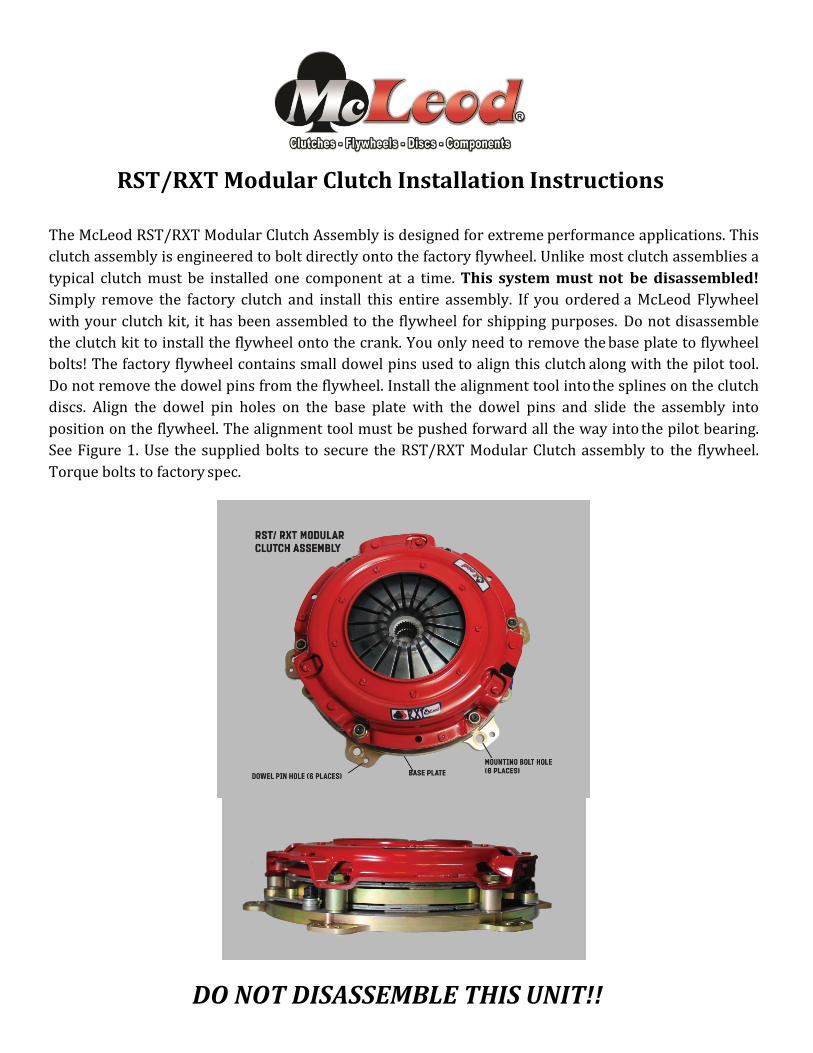
The McLeod RST/RXT Modular Clutch Assembly is designed for extreme performance applications. This clutch assembly is engineered to bolt directly onto the factory flywheel. Unlike most clutch assemblies a typical clutch must be installed one component at a time. This system must not be disassembled! Simply remove the factory clutch and install this entire assembly. If you ordered a McLeod Flywheel with your clutch kit, it has been assembled to the flywheel for shipping purposes. Do not disassemble the clutch kit to install the flywheel onto the crank. You only need to remove the base plate to flywheel bolts! The factory flywheel contains small dowel pins used to align this clutch along with the pilot tool. Do not remove the dowel pins from the flywheel. Install the alignment tool into the splines on the clutch discs. Align the dowel pin holes on the base plate with the dowel pins and slide the assembly into position on the flywheel. The alignment tool must be pushed forward all the way into the pilot bearing. See Figure 1. Use the supplied bolts to secure the RST/RXT Modular Clutch assembly to the flywheel. Torque bolts to factory spec.
DO NOT DISASSEMBLE THIS UNIT!!
Important Clutch Installation Hints
The following check list is a reminder of the necessary inspection points and precautions required to insure a trouble-‐free clutch installation.
Installation / Do’s
1) Determine cause of original clutch failure. Cause of first clutch failure (if not wear) MUST be found and corrected. If oil is present on clutch plate, cause of leak MUST be corrected before installation of new clutch unit.
2) Check splines on transmission input shaft for signs of abnormal wear or twisting. Slide new disc on spline by hand gently to check fit. Disc should move FREELY on splines.
3) Remove ALL oil or grease from friction surfaces on flywheel and cover assembly. Surfaces MUST be clean and dry. Also clean input shaft spline with a wire brush. Lubricate with dry graphite spray if needed.
4) To insure proper operation, friction surface of flywheel MUST be resurfaced. Check dowel pins, they must be smooth and straight.
5) If throw-‐out bearing is worn, replace it, better now than later. 6) Closely inspect pilot bearing or bushing for excessive wear to avoid transmission shaft misalignment.
Replace it if any doubts. 7) Use clutch alignment tool to insure disc and cover are properly aligned with pilot bearing. 8) If using an aftermarket scatter shield/bell housing, checking center hole run-‐out is highly recommended. 9) Be sure all special type bolts, if any, are replaced in their proper locations. 10) Torque all clutch cover bolts evenly, to factory recommended spec, using a progressive “criss-‐cross”
tightening pattern. 11) Before completing installation, inspect all clutch linkage parts (fork, clevis, pins, etc.) for signs of wear and
replace ALL worn pieces. Grease all pivot points in linkage system. 12) Adjust clutch pedal “free play” to correct specifications. Throw-‐out bearing should not be tight against
clutch fingers. 1/8” – ¼” is recommended, except cable linkage.
Installation / Don’ts Torque Specs 1) Don’t let any grease or oil contact ANY friction Surface. 5/16-‐18 Grade 8 25 Ft/Lbs 2) Don’t use an impact (air gun) to tighten cover bolts. 3/8-‐16 Grade 8 35 Ft/Lbs 3) Don’t let transmission weight rest on input shaft during 7/16-‐20 Grade 8 65 Ft/Lbs
installation. ½-‐20 Grade 8 75 Ft/Lbs
Limited Warranty McLeod Racing LLC, Products are warranted to be free from defects in material and workmanship for the period of ninety (90) days, from the date of purchase. McLeod does not warrant or make any representations concerning its products when not installed and used strictly in accordance with the manufacturer’s instructions for such; installation and operation, and in accordance with good installation and maintenance practices of the automotive industry. McLeod will not be held liable for the labor charges and other intangible or consequent losses that might be claimed as a result of the failure of any part, nor shall it be liable for damages or injury to persons or property resulting from the misuse or improper installation of any part subject to this warranty.
No merchandise may be returned for any reason unless prior return merchandise authorization number (RMA) has been obtained from McLeod.
McLeod reserves the right to examine all parts returned for warranty claim to determine whether or not any such part has failed because of a defect in material or workmanship. McLeod obligation under this warranty shall be limited to repairing, replacing or crediting, at its option, any part found to be defective. All products returned to McLeod for warranty inspection must be prepaid by the customer under this warranty. There are no other warranties, either expressed or implied, which extend beyond those set forth in the preceding paragraphs. I0003 www.mcleodracing.com (714) 630-‐2764