ibc 2006 - bentley communities · pdf filethe ibc 2006 static equivalent method for seismic...
TRANSCRIPT

IBC 2006 This document illustrates the method of Seismic Load (Static Equivalent method) as per IBC 2006

THE IBC 2006 STATIC EQUIVALENT METHOD FOR SEISMIC
ANALYSIS
OBJECTIVE
In this session, we will briefly go over the theoretical basis for equivalent static
force procedures such as IBC. We will also learn how to define seismic
parameters and weights, combine gravity loads with lateral loads, view the
generated lateral loads, handle cases like tension-only bracing members, etc.
GENERAL OVERVIEW When a building is subjected to an earthquake, it undergoes vibrations. The
weights of the structure, when accelerated along the direction of the earthquake,
induce forces in the building. Normally, an elaborate dynamic analysis called
time history analysis is required to solve for displacements, forces and reactions
resulting from the seismic activity. However, codes like IBC provide a static
method of solving for those values. The generalized procedure used in those
methods consists of 3 steps
Step 1: Calculate Base Shear = Factor Cs * Weight W where "Cs" (seismic
coefficient) is calculated from terms which take into consideration the
Importance factor of the building, Site Class and soil characteristics, etc. W is
the total vertical weight derived from dead weight of the building and other
imposed weights.
Step 2: The base shear is then distributed over the height of the building as a
series of point loads.
Step 3: The model is then analyzed for the horizontal loads generated in step 2.
The input required in STAAD consists of 2 parts.
Part 1, which appears under a heading called DEFINE IBC LOAD contains the
terms used to compute "f" and "W" described in step 1. Part 2, which appears
within a load case, contains the actual instruction to generate the forces
described in step 2 and analyze the structure for those forces.
On a broad basis, the rules described in section 1613 of the ICC IBC-2006 code
(except 1613.5.5) have been implemented. This section directs the engineer to
Section 12.8 of the ASCE 7-2005 code. The specific section numbers of ASCE
7- those which are implemented, and those which are not implemented, are
shown in the table below.

The associated pages of the ASCE 7-2005 code are 115 thru 129.
Methodology
The design base shear is computed in accordance with the equations shown
below
The seismic response coefficient, Cs, is determined in accordance with the
following equation:
For IBC 2006, Cs need not exceed the following limits defined in ASCE 7-05:-
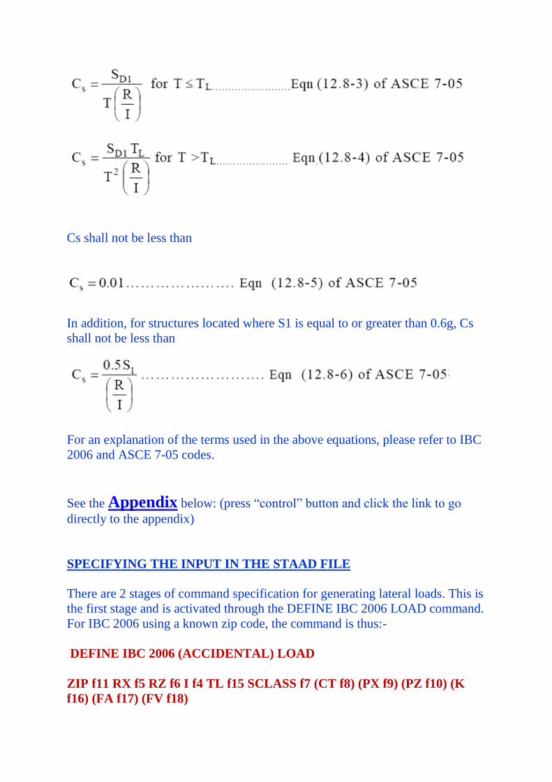
Cs shall not be less than
In addition, for structures located where S1 is equal to or greater than 0.6g, Cs
shall not be less than
For an explanation of the terms used in the above equations, please refer to IBC
2006 and ASCE 7-05 codes.
See the Appendix below: (press “control” button and click the link to go
directly to the appendix)
SPECIFYING THE INPUT IN THE STAAD FILE
There are 2 stages of command specification for generating lateral loads. This is
the first stage and is activated through the DEFINE IBC 2006 LOAD command.
For IBC 2006 using a known zip code, the command is thus:-
DEFINE IBC 2006 (ACCIDENTAL) LOAD
ZIP f11 RX f5 RZ f6 I f4 TL f15 SCLASS f7 (CT f8) (PX f9) (PZ f10) (K
f16) (FA f17) (FV f18)
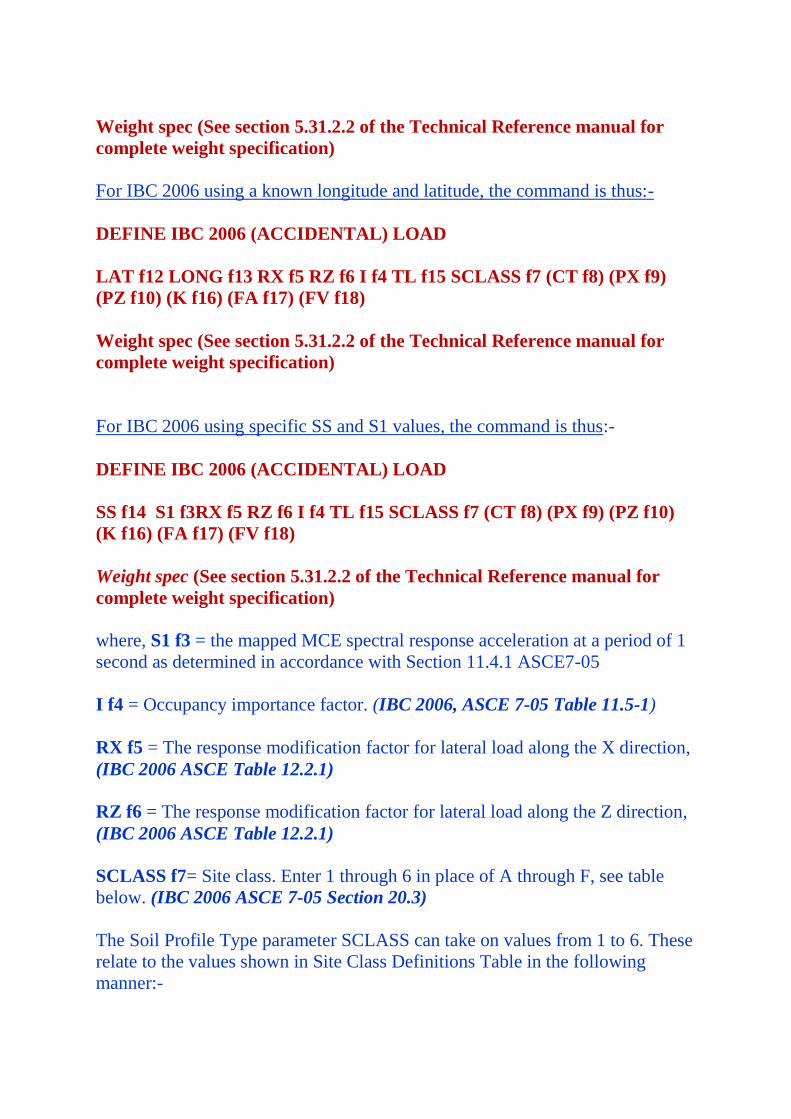
Weight spec (See section 5.31.2.2 of the Technical Reference manual for
complete weight specification)
For IBC 2006 using a known longitude and latitude, the command is thus:-
DEFINE IBC 2006 (ACCIDENTAL) LOAD
LAT f12 LONG f13 RX f5 RZ f6 I f4 TL f15 SCLASS f7 (CT f8) (PX f9)
(PZ f10) (K f16) (FA f17) (FV f18)
Weight spec (See section 5.31.2.2 of the Technical Reference manual for
complete weight specification)
For IBC 2006 using specific SS and S1 values, the command is thus:-
DEFINE IBC 2006 (ACCIDENTAL) LOAD
SS f14 S1 f3RX f5 RZ f6 I f4 TL f15 SCLASS f7 (CT f8) (PX f9) (PZ f10)
(K f16) (FA f17) (FV f18)
Weight spec (See section 5.31.2.2 of the Technical Reference manual for
complete weight specification)
where, S1 f3 = the mapped MCE spectral response acceleration at a period of 1
second as determined in accordance with Section 11.4.1 ASCE7-05
I f4 = Occupancy importance factor. (IBC 2006, ASCE 7-05 Table 11.5-1)
RX f5 = The response modification factor for lateral load along the X direction,
(IBC 2006 ASCE Table 12.2.1)
RZ f6 = The response modification factor for lateral load along the Z direction,
(IBC 2006 ASCE Table 12.2.1)
SCLASS f7= Site class. Enter 1 through 6 in place of A through F, see table
below. (IBC 2006 ASCE 7-05 Section 20.3)
The Soil Profile Type parameter SCLASS can take on values from 1 to 6. These
relate to the values shown in Site Class Definitions Table in the following
manner:-
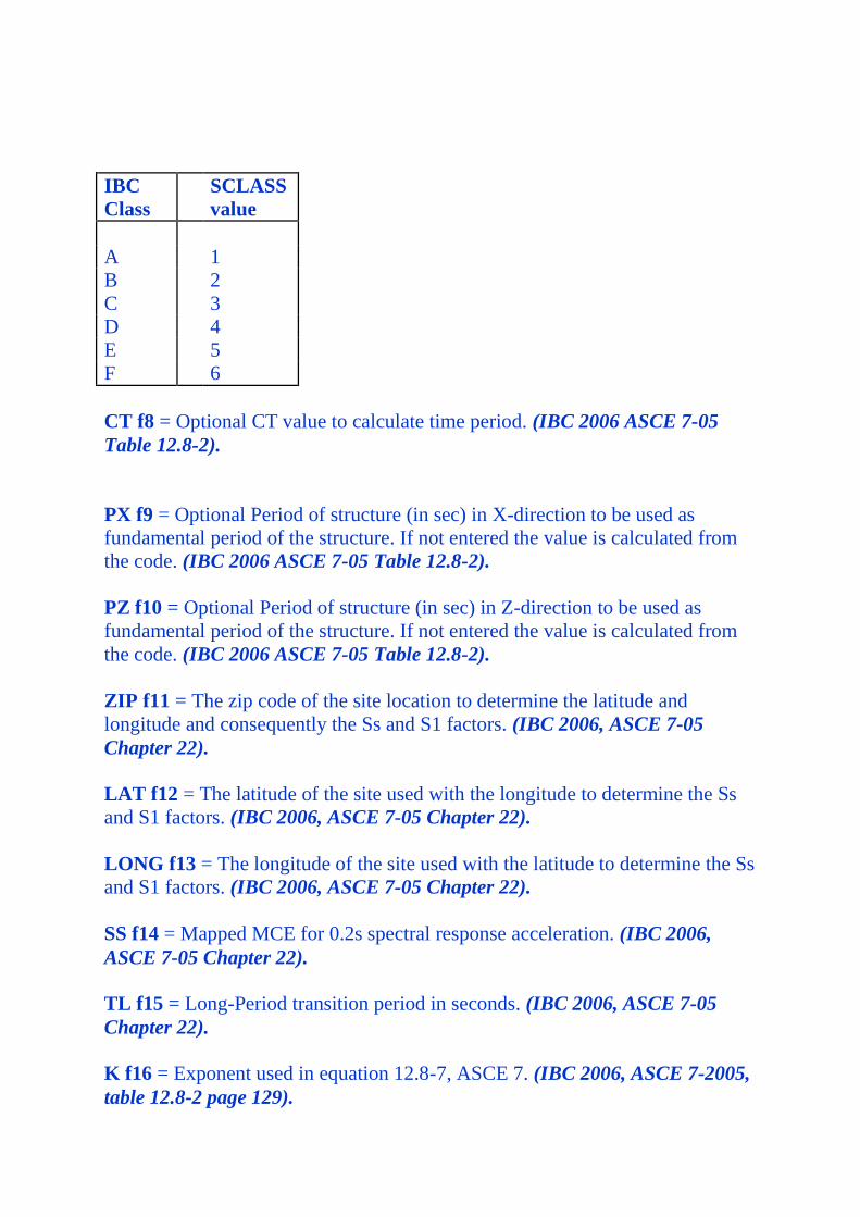
IBC
Class
SCLASS
value
A 1
B 2
C 3
D 4
E 5
F 6
CT f8 = Optional CT value to calculate time period. (IBC 2006 ASCE 7-05
Table 12.8-2).
PX f9 = Optional Period of structure (in sec) in X-direction to be used as
fundamental period of the structure. If not entered the value is calculated from
the code. (IBC 2006 ASCE 7-05 Table 12.8-2).
PZ f10 = Optional Period of structure (in sec) in Z-direction to be used as
fundamental period of the structure. If not entered the value is calculated from
the code. (IBC 2006 ASCE 7-05 Table 12.8-2).
ZIP f11 = The zip code of the site location to determine the latitude and
longitude and consequently the Ss and S1 factors. (IBC 2006, ASCE 7-05
Chapter 22).
LAT f12 = The latitude of the site used with the longitude to determine the Ss
and S1 factors. (IBC 2006, ASCE 7-05 Chapter 22).
LONG f13 = The longitude of the site used with the latitude to determine the Ss
and S1 factors. (IBC 2006, ASCE 7-05 Chapter 22).
SS f14 = Mapped MCE for 0.2s spectral response acceleration. (IBC 2006,
ASCE 7-05 Chapter 22).
TL f15 = Long-Period transition period in seconds. (IBC 2006, ASCE 7-05
Chapter 22).
K f16 = Exponent used in equation 12.8-7, ASCE 7. (IBC 2006, ASCE 7-2005,
table 12.8-2 page 129).

FA f17 = Optional Short-Period site coefficient at 0.2s. Value must be provided
if SCLASS set to F (i.e. 6). (IBC 2006, ASCE 7-05 Section 11.4.3).
FV f18 = Optional Long-Period site coefficient at 1.0s. Value must be provided
if SCLASS set to F (i.e. 6). (IBC 2006, ASCE 7-05 Section 11.4.3).
Example
There are 3 methods to define IBC 2006. The 3 methods are defined below.
Method 1:- Input Zip code
DEFINE IBC 2006
ZIP 92887 I 1.25 RX 2.5 RZ 2.5 SCLASS 4 TL 12 FA 1 FV 1.5
SELFWEIGHT
JOINT WEIGHT
51 56 93 100 WEIGHT 650
MEMBER WEIGHT
151 TO 156 158 159 222 TO 225 324 TO 331 UNI 45
Method 2:- Input Latitude and Longitude
DEFINE IBC 2006
LAT 33.8845 LONG -117.9274 I 1.25 RX 2.5 RZ 2.5 SCLASS 4 TL 12 FA 1
FV 1.5
SELFWEIGHT
JOINT WEIGHT
51 56 93 100 WEIGHT 650
MEMBER WEIGHT
151 TO 156 158 159 222 TO 225 324 TO 331 UNI 45
Method 3:- Input Ss and S1 values
DEFINE IBC 2006 ACCIDENTAL
SS 2.15822 S1 0.80585 I 1 RX 3 RZ 4 SCLASS 4 TL 12
SELFWEIGHT
JOINT WEIGHT
51 56 93 100 WEIGHT 650
MEMBER WEIGHT
151 TO 156 158 159 222 TO 225 324 TO 331 UNI 45

Steps used to calculate and distribute the base shear are as follows:
1. The Time Period of the structure is calculated based on section 12.8.1 of
ASCE 7-05 (IBC 2006). This is reported in the output as Ta.
2. The period is also calculated in accordance with the Rayleigh method. This is
reported in the output as T.
3. The user may override the Rayleigh based period by specifying a value for
PX or PZ (Items f7 and f8) depending on the direction of the IBC load.
4. The governing Time Period of the structure is then chosen between the above
two periods, and the additional guidance provided in section 12.8.2.1 of ASCE
7-05 (IBC 2006). The resulting value is reported as "Time Period used" in the
output file.
5. The Design Base Shear is calculated based on equation 12.8-1 of ASCE 7-05
(IBC 2006). It is then distributed at each floor using the rules of clause 12.83,
equations 12.8-11, 12.8-12 and 12.8-13 of ASCE 7-05.
6. If the ACCIDENTAL option is specified, the program calculates the
additional torsional moment. The lever arm for calculating the torsional moment
is obtained as 5% of the building dimension at each floor level perpendicular to
the direction of the IBC load (section 12.8.4.2 of ASCE 7-05 for IBC 2006). At
each joint where a weight is located, the lateral seismic force acting at that joint
is multiplied by this lever arm to obtain the torsional moment at that joint.
The following example shows the commands required to enable the program to
generate the lateral loads. Users may refer to Section 5.32.12 of the Technical
Reference Manual for this information.
Example
LOAD 1 (SEISMIC LOAD IN X DIRECTION)
IBC LOAD X 0.75
LOAD 2 (SEISMIC LOAD IN Z DIRECTION)
IBC LOAD Z 0.75
TO SPECIFY IBC 2006 FROM THE GUI
The static equivalent method for performing dynamic analysis per the IBC 2006
code has been implemented in STAAD.Pro 2007 Build 02. This option can be
accessed from the General | Load page as explained below.
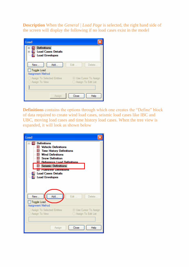
Description When the General | Load Page is selected, the right hand side of
the screen will display the following if no load cases exist in the model
Definitions contains the options through which one creates the “Define” block
of data required to create wind load cases, seismic load cases like IBC and
UBC, moving load cases and time history load cases. When the tree view is
expanded, it will look as shown below

Select Seismic Definitions and click on Add. In the dialog box that comes up,
select IBC 2006 from the drop-down list.
In this dialog box, we can specify the various parameters as described below
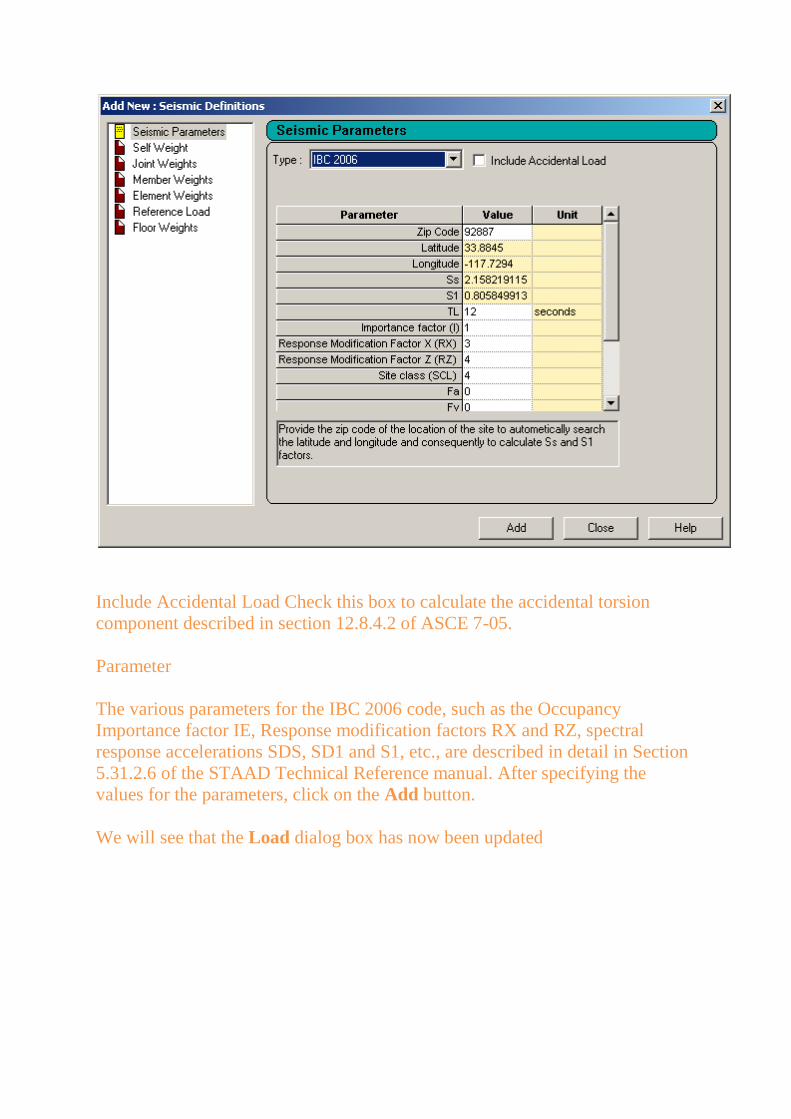
Include Accidental Load Check this box to calculate the accidental torsion
component described in section 12.8.4.2 of ASCE 7-05.
Parameter
The various parameters for the IBC 2006 code, such as the Occupancy
Importance factor IE, Response modification factors RX and RZ, spectral
response accelerations SDS, SD1 and S1, etc., are described in detail in Section
5.31.2.6 of the STAAD Technical Reference manual. After specifying the
values for the parameters, click on the Add button.
We will see that the Load dialog box has now been updated
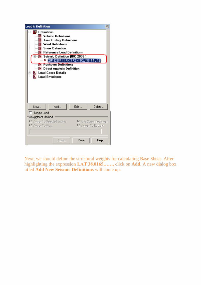
Next, we should define the structural weights for calculating Base Shear. After
highlighting the expression LAT 38.0165……, click on Add. A new dialog box
titled Add New Seismic Definitions will come up.
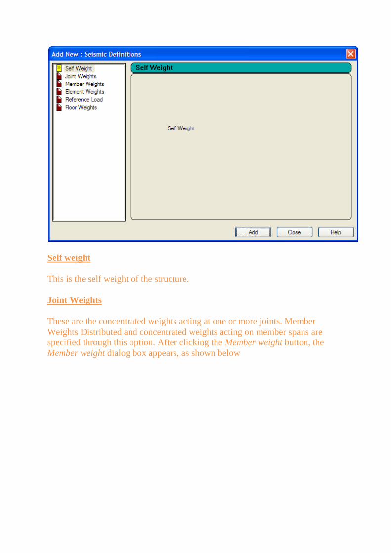
Self weight
This is the self weight of the structure.
Joint Weights
These are the concentrated weights acting at one or more joints. Member
Weights Distributed and concentrated weights acting on member spans are
specified through this option. After clicking the Member weight button, the
Member weight dialog box appears, as shown below
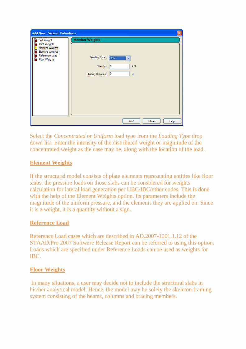
Select the Concentrated or Uniform load type from the Loading Type drop
down list. Enter the intensity of the distributed weight or magnitude of the
concentrated weight as the case may be, along with the location of the load.
Element Weights
If the structural model consists of plate elements representing entities like floor
slabs, the pressure loads on those slabs can be considered for weights
calculation for lateral load generation per UBC/IBC/other codes. This is done
with the help of the Element Weights option. Its parameters include the
magnitude of the uniform pressure, and the elements they are applied on. Since
it is a weight, it is a quantity without a sign.
Reference Load
Reference Load cases which are described in AD.2007-1001.1.12 of the
STAAD.Pro 2007 Software Release Report can be referred to using this option.
Loads which are specified under Reference Loads can be used as weights for
IBC.
Floor Weights
In many situations, a user may decide not to include the structural slabs in
his/her analytical model. Hence, the model may be solely the skeleton framing
system consisting of the beams, columns and bracing members.

Under these circumstances, the loads which act on the slab can no longer be
applied on the structure using the ELEMENT PRESSURE options. This is
because there are no elements to represent the slab. So, an alternative is to apply
the load using the FLOOR LOAD option. It is described in detail in section
5.32.4 of the Technical Reference manual.
Within a UBC/IBC/other codes definition, the FLOOR WEIGHT is the
counterpart for the FLOOR LOAD just as MEMBER WEIGHT is the
counterpart for a MEMBER LOAD, and an ELEMENT WEIGHT is the
counterpart for an ELEMENT LOAD.
Its parameters are hence very similar to what are found in a normal FLOOR
LOAD definition. XRANGE, YRANGE and ZRANGE options allow the user
to narrow in on panels at specific regions of the building. The pressure value is
provided as a quantity without sign because it is contributing to the overall
weight - a numerically positive term.
Once we finish specifying the seismic definitions, we can start adding load
cases.
To do that, select Load Cases Details and click on Add.
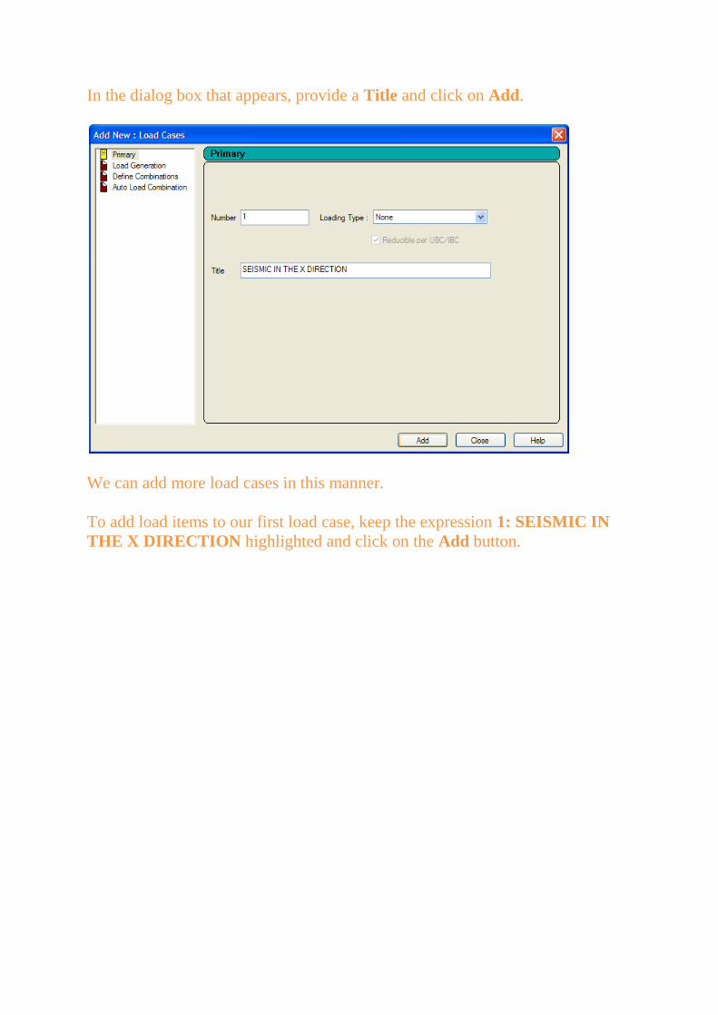
In the dialog box that appears, provide a Title and click on Add.
We can add more load cases in this manner.
To add load items to our first load case, keep the expression 1: SEISMIC IN
THE X DIRECTION highlighted and click on the Add button.
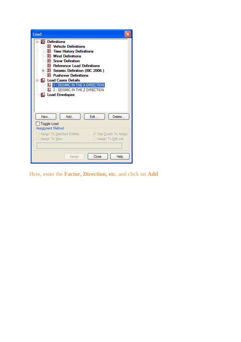
Here, enter the Factor, Direction, etc. and click on Add

The Load dialog box will show the new load item
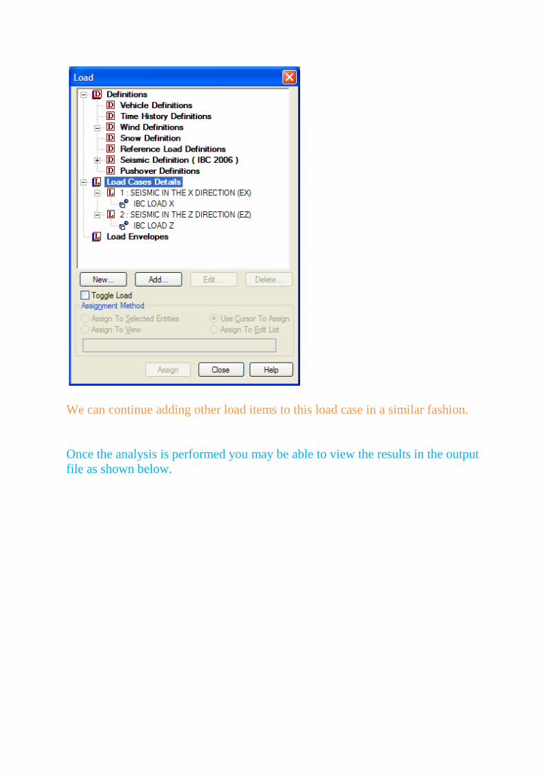
We can continue adding other load items to this load case in a similar fashion.
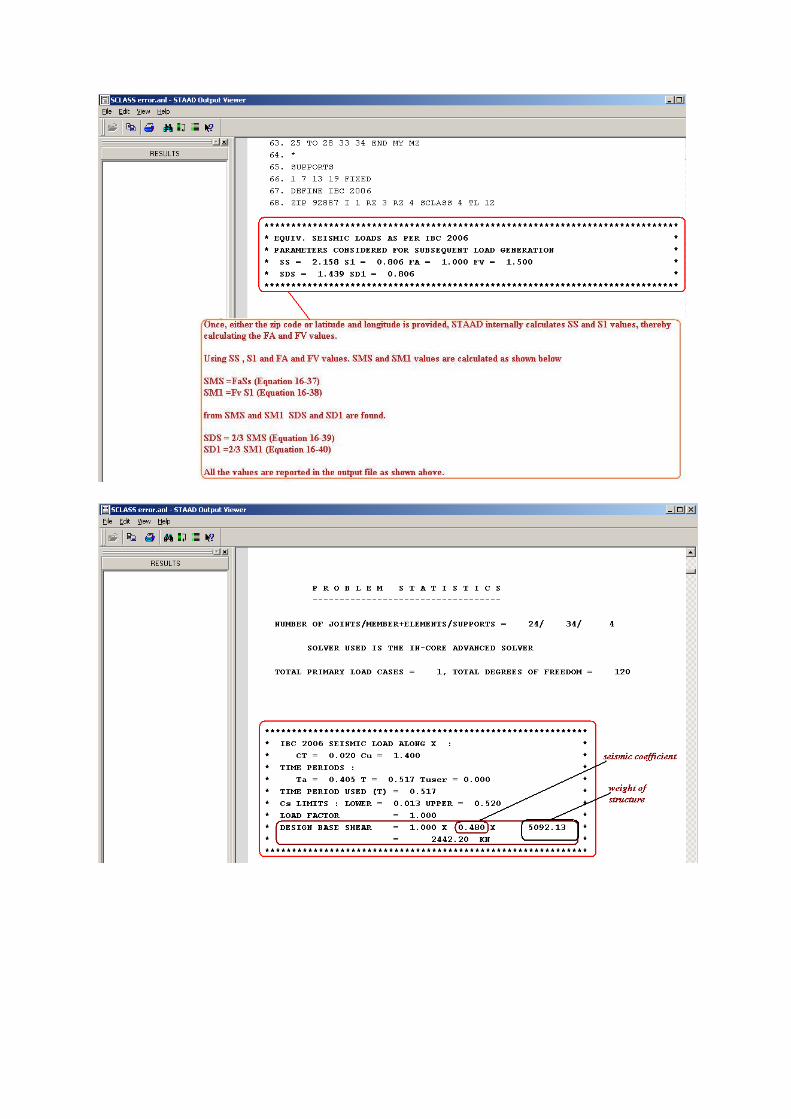
Once the analysis is performed you may be able to view the results in the output
file as shown below.


Appendix :1
Regards
*******************
Nihesh.N
STAAD Technical Support
Bentley Systems
TEL: 714-974-2500 ex 5484
*******************