ibm 200/400gb lto-2 tape drive: user.s...
TRANSCRIPT
IBM 200/400GB LTO-2 Tape Drive
User’s Guide
Note:Please carefully review the maintenance procedures in Chapter 4, “Operating the tapedrive”, on page 31 as periodic maintenance (cleaning, firmware upgrades, etc.) are notcovered by the IBM Warranty. Repairs or exchanges resulting from improper maintenancewill result in billable service charges.
���


IBM 200/400GB LTO-2 Tape Drive
User’s Guide
���

NoteBefore using this guide and the product it supports, read the information in “Safety: Read first” on page iii and Appendix E,“Notices”, on page 89
First Edition (April 2003)
© Copyright International Business Machines Corporation 2003. All rights reserved.US Government Users Restricted Rights – Use, duplication or disclosure restricted by GSA ADP Schedule Contractwith IBM Corp.
Safety: Read first
Before installing this product, read the Safety Information.
Antes de instalar este produto, leia as Informações de Segurança.
Pred instalací tohoto produktu si prectete prírucku bezpecnostních instrukcí.
Læs sikkerhedsforskrifterne, før du installerer dette produkt.
Ennen kuin asennat tämän tuotteen, lue turvaohjeet kohdasta Safety Information.
Avant d’installer ce produit, lisez les consignes de sécurité.
Vor der Installation dieses Produkts die Sicherheitshinweise lesen.
Prima di installare questo prodotto, leggere le Informazioni sulla Sicurezza.
Lees voordat u dit product installeert eerst de veiligheidsvoorschriften.
Les sikkerhetsinformasjonen (Safety Information) før du installerer dette produktet.
Antes de instalar este produto, leia as Informações sobre Segurança.
Pred inštaláciou tohto zariadenia si pečítaje Bezpečnostné predpisy.
Antes de instalar este producto lea la información de seguridad.
© Copyright IBM Corp. 2003 iii

Läs säkerhetsinformationen innan du installerar den här produkten.
iv IBM 200/400GB LTO-2 Tape Drive: User’s Guide

Contents
Safety: Read first . . . . . . . . . . iii
Preface . . . . . . . . . . . . . . viiAbout this book . . . . . . . . . . . . . viiRelated publications . . . . . . . . . . . vii
Chapter 1. Introduction . . . . . . . . 1Cartridge compatibility . . . . . . . . . . . 2Speed matching and channel calibration . . . . . 2Sleep mode . . . . . . . . . . . . . . . 2Software description . . . . . . . . . . . . 3
Chapter 2. Installing the tape drive . . . 5Package contents . . . . . . . . . . . . . 5Installation requirements . . . . . . . . . . 5Installing the drive in IBM servers . . . . . . . 5Rear view of the SCSI drive . . . . . . . . . 7Step 1. Remove power from the host . . . . . . 7Step 2. Set the SCSI ID . . . . . . . . . . . 8
Setting the SCSI ID with jumpers . . . . . . 8Setting the SCSI ID with a SCSI ID switch . . . 8Supplying TERMPOWER . . . . . . . . . 9
Step 3. Mount the tape drive into the server . . . 10Step 4. Connect and test power to the tape drive . . 11Step 5. Connect the internal SCSI cable . . . . . 11Step 6. Run drive diagnostics . . . . . . . . 11Step 7. Install the device drivers . . . . . . . 11Step 8. Updating the configuration . . . . . . 12Step 9. Installing the backup and restore software 12
Chapter 3. Using the media . . . . . . 13Data cartridge . . . . . . . . . . . . . 13Cleaning cartridges . . . . . . . . . . . . 15Setting the write-protect switch . . . . . . . . 16Handling the cartridges . . . . . . . . . . 16
Ensure proper packaging . . . . . . . . . 16Provide proper acclimation and environmentalconditions . . . . . . . . . . . . . . 18Perform a thorough inspection . . . . . . . 18Handle the cartridge carefully . . . . . . . 18Examples of cartridge problems . . . . . . 19
Repositioning or reattaching a leader pin . . . . 20Repositioning a leader pin . . . . . . . . 20Reattaching a leader pin . . . . . . . . . 22
Environmental and shipping specifications for tapecartridges . . . . . . . . . . . . . . . 27Disposing of tape cartridges . . . . . . . . . 28Ordering media supplies . . . . . . . . . . 28
Ordering custom bar code labels . . . . . . 29
Chapter 4. Operating the tape drive . . 31Status light . . . . . . . . . . . . . . 32Unload button . . . . . . . . . . . . . 33Single-character display . . . . . . . . . . 33
Single red dot . . . . . . . . . . . . 33Inserting a tape cartridge . . . . . . . . . . 34Removing a tape cartridge . . . . . . . . . 35Cleaning the drive head . . . . . . . . . . 35Selecting a diagnostic or maintenance function . . 36Exiting maintenance mode . . . . . . . . . 45Updating the firmware . . . . . . . . . . 45
Chapter 5. Resolving problems . . . . 47Methods of receiving errors and messages . . . . 47
Descriptions and corrective actions for errors andmessages . . . . . . . . . . . . . . 49
Resolving problems reported by the server . . . . 53Fixing SCSI bus errors . . . . . . . . . . 53
Resolving media-related problems . . . . . . . 55
Chapter 6. Servicing the tape drive . . 57Removing a SCSI tape drive from an enclosure . . 57Manually removing a tape cartridge . . . . . . 58
Removing the Cartridge . . . . . . . . . 58Fixing an internal jam . . . . . . . . . . 61
Appendix A. Tools and supplies . . . . 69
Appendix B. TapeAlert flags . . . . . 71TapeAlert Flags supported by the drive . . . . . 71
Appendix C. Specifications . . . . . . 75
Appendix D. Product warranty andsupport information . . . . . . . . . 77Warranty period . . . . . . . . . . . . . 77
Problem determination . . . . . . . . . 77Warranty service and support . . . . . . . 78International warranty service . . . . . . . 78Purchasing additional services . . . . . . . 79
IBM Statement of Limited Warranty Z125-4753-068/2000 . . . . . . . . . . . . . . . . 80
Part 1 - General Terms. . . . . . . . . . 80Part 2 - Country-unique Terms . . . . . . . 82
Appendix E. Notices . . . . . . . . . 89Federal Communications Commission (FCC)Statement . . . . . . . . . . . . . . . 90
© Copyright IBM Corp. 2003 v

vi IBM 200/400GB LTO-2 Tape Drive: User’s Guide
Preface
About this bookThis manual contains information on the IBM 200/400 GB LTO-2 Internal TapeDrive. It is divided into the following parts:
Part 1: Installation, use, and maintenance guide
This section contains the product description, installation and operatinginstructions, and maintenance information in the following languages:v Englishv Germanv Frenchv Spanishv Italianv Simplified Chinesev Traditional Chinesev Koreanv Japanese
Part 2: Appendixes
This section contains problem-solving, service, warranty, and notice information.
Be sure to retain your proof of purchase. It might be required for warranty service.
Note: The illustrations in this manual might be slightly different from yourhardware.
Related publicationsRefer to the following publication for additional information:v IBM Total Storage LTO Ultrium Tape Drive SCSI Reference, GA32-0450, provides the
supported SCSI commands and protocol that govern the behavior of the SCSIinterface for all models of the IBM Ultrium Tape Drive.
© Copyright IBM Corp. 2003 vii

viii IBM 200/400GB LTO-2 Tape Drive: User’s Guide
Chapter 1. Introduction
The IBM 200/400 GB LTO-2 Internal Tape Drive is a fast/wide SCSI-3 tape drivefor backing up and archiving files. These files can include multimedia, imaging,transaction processing, large databases, and other storage-intensive applications.
The IBM LTO- 2 Tape Drive is a high-performance, high-capacity data-storagedevice that is designed to backup and restore Open Systems applications. Thedrive can be integrated into an IBM external enclosure, such as a 3503B1X, ordirectly into some xSeries servers. The LTO-2 is the second-generation tape drive inthe Ultrium series of products.
The LTO-2 offers the following features:v Native storage capacity of up to 200 GB per cartridge (400 GB assuming 2:1 LTO
Data Compression)v Native sustained data transfer rate of up to 35 MB per second (up to 70 MB
assuming 2:1 LTO Data Compression)
© Copyright IBM Corp. 2003 1

Cartridge compatibilityThe LTO-2 uses the IBM LTO Ultrium 200 GB Data Cartridge and is compatiblewith the cartridges of its predecessor, the IBM Ultrium Internal Tape Drive (calledGeneration 1). The LTO-2 performs the following functions:v Reads and writes Generation 2 cartridges to Generation 2 formatv Reads and writes Generation 1 cartridges to Generation 1 formatv Does not write Generation 2 cartridges to Generation 1 formatv Does not write Generation 1 cartridges to Generation 2 format
The LTO-2 reads tapes that have been written by other licensed Ultrium 2 drives. Italso writes to tapes that can be read by other licensed Ultrium 2 drives.
In addition to using the IBM LTO-2 Ultrium Data Cartridge with up to 200 GBcapacity, the LTO-2 also offers read/write capability for certified LTO Ultrium tapecartridges.
Speed matching and channel calibrationTo improve system performance, the LTO-2 uses a technique called speed matchingto dynamically adjust its native (uncompressed) data rate to the slower data rate ofa server. With speed matching, the drive operates at one of five speeds whenreading or writing the Generation 2 cartridge format to achieve a native data rateof 17.5, 21.9, 26.25, 30.63, or 35 MB per second (MB/s). If the server’s net(compressed) data rate is between two of the preceding native data rates, the drivecalculates which of the two data rates at which to operate. (For example, if theserver transfers data at 60 MB/s on the host bus, at 2:1 compression its net datarate is 30 MB/s. The drive will then dynamically choose to operate at a native datarate of 26.25 or 30.63 MB/s, whichever enables it to successfully receive thegreatest amount of compressed data over the network.) Speed matchingdramatically reduces backhitch, the condition that occurs when a tape stops,reverses, and restarts motion. A backhitch is usually the result of a mismatchbetween the data rates of the server and the drive.
System performance is further optimized by a feature called channel calibration, inwhich the drive automatically customizes each read/write data channel tocompensate for variations in such things as the recording channel’s transferfunction, the media, and characteristics of the drive head.
Sleep modeTo conserve energy when circuit functions are not needed for drive operation, theLTO-2 features a power-management function that causes the drive’s electronics toenter a low-power mode known as sleep mode. To enter sleep mode, the drive mustbe inactive for a minimum of 15 minutes; to exit, the drive must receive acommand across the SCSI interface or a load or unload request. When in sleepmode, the drive’s response time to commands that do not require media motionincreases by up to 10 microseconds. Commands that require media motion may bedelayed an additional 100 milliseconds because the tape must be retensioned.
2 IBM 200/400GB LTO-2 Tape Drive: User’s Guide

Software descriptionThe IBM 200/400 GB LTO-2 Internal Tape Drive includes trial-version backupapplication CDs. These CDs contain popular backup and restore applications forMicrosoft® Windows NT®, Novell NetWare, and other operating systems. You caninstall the application you choose for your computer system by following theinstallation instructions that come with the CD you select. However, these trialversions of the software expire after 30 to 90 days, depending on the applicationyou use.
You can use the trial period to determine the best application for your specificcomputer configuration. For information on purchasing a permanent installationcopy of the desired tape drive backup application, go to the IBM Web site atwww.pc.ibm.com/ww/eserver/xseries/tape.html or follow the instructions on theCD.
The CD also contains backup applications that are used with other products butare not applicable to the 200/400 GB LTO-2 Internal Tape Drive. Please go towww.pc.ibm.com/us/compat, click on Tape Backup Units, then search for 59P6744to see the current support list.
Chapter 1. Introduction 3

4 IBM 200/400GB LTO-2 Tape Drive: User’s Guide

Chapter 2. Installing the tape drive
This section contains information on installing the tape drive in IBM servers andother computers.
Package contentsIn addition to this book, this package contains:v IBM 200/400 GB LTO-2 Internal Tape Drivev Mounting screwsv Jumpersv Backup application CDs (trial versions)v Safety Information manualv Cleaning cartridgev Device drivers in the Device Driver folder on the User’s Guide CD.v Internal SCSI cable
Contact your place of purchase if an item is missing or damaged. Be sure to retainyour proof of purchase and packing material. They might be required to receivewarranty service.
Installation requirementsTo install this drive, you must have the following:v Low-voltage (Ultra2)1 or a SCSI-3 host adapterv Documentation for your computer, SCSI bus adapter or external closurev A SCSI-3 active terminator if you are installing the tape drive at the end of a
SCSI-3 device chain2 or an LVD active terminator if you are installing the tapedrive at the end of an LVD SCSI device chain2
v Phillips and flat blade screwdrivers for the mounting screws and for openingyour computer
v Flat-nose pliers (optional) to install and remove jumpersv An available 5.25-inch full high drive bay
Installing the drive in IBM serversThe tape drive is compatible with many IBM xSeries servers. Please go toww.pc.ibm.com/us/compat, click on Tape Backup Units, then search for 59P6744for a complete and current list of supported IBM hardware and software.
1. This tape drive can be installed on an Ultra2 LVD SCSI device chain, but doing so will limit the performance of the drive.
2. SCSI termination might be provided with your computer or SCSI adapter. Refer to the documentation that comes with yourcomputer or SCSI adapter for more information.
© Copyright IBM Corp. 2003 5
Attention:To avoid static electricity damage when you handle the IBM 200/400GBLTO-2 Tape Drive, use the following precautions:v Limit your movement. Movement can cause static electricity to build
around you.v Always handle the LTO-2 carefully. Never touch exposed circuitry.v Prevent others from touching the LTO-2.v Before you unpack and install the LTO-2 into an enclosure, touch its
static-protective packaging to an unpainted metal surface on the enclosurefor at least 2 seconds. This reduces static electricity in the packaging andyour body.
v When possible, remove the LTO-2 from its static-protective packaging andinstall it directly into an enclosure without setting it down. When this isnot possible, place the tape drive’s packaging on a smooth, level surfaceand place the tape drive on the packaging.
v Do not place the LTO-2 on the cover of the enclosure or on any other metalsurface.
The steps that follow describe how to install the LTO-2 into a server.
Note: Depending on the type of xSeries server, installation procedures may vary.Before starting this installation, read these instructions and compare them tothe drive installation instructions for your server.
6 IBM 200/400GB LTO-2 Tape Drive: User’s Guide

Rear view of the SCSI drive�1� Feature switches
�2� SCSI connector
�3� SCSI ID connector
�4� Power connector
�5� Library/Drive Interface (LDI or RS-422 interface) connector
Step 1. Remove power from the host__ 1. Power-off the server (or the unit that provides power to the drive)__ 2. Disconnect the power cord from the electrical outlet.
Figure 1. Rear view of the IBM 200/400GB LTO-2 Tape Drive
Chapter 2. Installing the tape drive 7
Step 2. Set the SCSI IDYou can set the SCSI ID in one of two ways:v By placing jumpers on the SCSI ID connectorv By using a remote SCSI ID switch that is connected to the SCSI ID connector
The sections that follow describe each method of setting the SCSI ID.
Setting the SCSI ID with jumpersYou can set the SCSI ID on the LTO-2 by installing 2-mm jumpers on the drive’sSCSI ID connector (see �3� in Figure 1 on page 7). Your tape drive may come set toa default SCSI configuration, with jumpers already installed. You can change theSCSI ID by rearranging, adding, or removing jumpers.
To set the SCSI ID:__ 1. Locate the SCSI ID connector (see �3� in Figure 1 on page 7).__ 2. Before attaching the SCSI bus cable to the server, decide the SCSI ID number
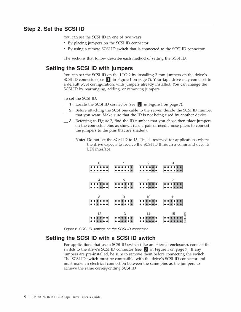
that you want. Make sure that the ID is not being used by another device.__ 3. Referring to Figure 2, find the ID number that you chose then place jumpers
on the connector pins as shown (use a pair of needle-nose pliers to connectthe jumpers to the pins that are shaded).
Note: Do not set the SCSI ID to 15. This is reserved for applications wherethe drive expects to receive the SCSI ID through a command over itsLDI interface.
Setting the SCSI ID with a SCSI ID switchFor applications that use a SCSI ID switch (like an external enclosure), connect theswitch to the drive’s SCSI ID connector (see �3� in Figure 1 on page 7). If anyjumpers are pre-installed, be sure to remove them before connecting the switch.The SCSI ID switch must be compatible with the drive’s SCSI ID connector andmust make an electrical connection between the same pins as the jumpers toachieve the same corresponding SCSI ID.
Figure 2. SCSI ID settings on the SCSI ID connector
8 IBM 200/400GB LTO-2 Tape Drive: User’s Guide

Supplying TERMPOWERTo supply TERMPOWER to the bus, locate one of the five jumpers shipped withthe LTO-2 and place it on the SCSI ID connector as shown in the following figure.Place the jumper on the pins that are shaded.
A67E
0049
Chapter 2. Installing the tape drive 9

Step 3. Mount the tape drive into the serverTo mount the LTO-2 into a server:__ 1. Remove the cover of your server (refer to the instructions in the server’s
documentation).__ 2. Place the drive into the server so that its tape load compartment faces the
front of the server.__ 3. Use the supplied mounting screws to mount drive into server. Some server
installations require use of mounting rails. For these applications, use themounting screws to attach rails to the side of the LTO-2 drive and then slidethe drive into the server.
Attention: When inserted into the LTO-2, the length of the mounting screws mustnot exceed 3.5 mm (0.14 in.) inside the chassis. If the length exceeds thismeasurement, the tape drive may become damaged.
Figure 3. Mounting holes on Ultrium 2 Tape Drive. The holes are located on both sides of thedrive.
10 IBM 200/400GB LTO-2 Tape Drive: User’s Guide

Step 4. Connect and test power to the tape driveThe LTO-2 does not contain its own power source; it must be powered externally.
To connect and test power to the LTO-2:__ 1. Ensure that the server (or unit that supplies power to the drive) is powered
off.__ 2. Ensure that the power cord is disconnected from both the server and the
power outlet.__ 3. Connect the server’s internal power cable to the power connector on the
drive (see �4� in Figure 1 on page 7). Ensure that the connector is properlyconnected.
__ 4. Connect the power cord to the server and to the electrical outlet.__ 5. Review the location of the single-character display and the status light on
page 31 (if your drive does not have a bezel, note that the bulb of the statuslight is recessed and the light is not visible until lit). To ensure that the driveis receiving power, watch for the following while turning on the power tothe server:v The single-character display presents a series of random characters, then
becomes blank (not lit).
Note: If the single-character display does not come on, the drive maynot be getting power.
v The status light briefly becomes solid amber, then becomes solid green.__ 6. Power-off the server.__ 7. Disconnect the power cord from both the server and the electrical outlet.
Step 5. Connect the internal SCSI cableConnect one end of the SCSI cable that came with the tape drive to the SCSIconnector on the drive (see �2� in Figure 1 on page 7). Connect the other end to theSCSI connector within your server.
Step 6. Run drive diagnostics__ 1. Replace the cover on the server.__ 2. Connect the power cord to both the server and the electrical outlet, then
power-on the server.__ 3. Run one or more of the following tape drive diagnostics. If an error code
appears on the single-character display, go to Table 8 on page 49.v Function Code 1 - Run Tape Drive Diagnostics (see page 36).v Function Code 6 - Run Wrap Test (see page 39).
__ 4. Power-off the server, then disconnect the power cord from both the serverand the electrical outlet.
Step 7. Install the device driversFor information about installing device drivers, refer to the Readme file in theDevice Driver folder of the User’s Guide CD.
Chapter 2. Installing the tape drive 11

Step 8. Updating the configurationFor most computers, the configuration-setup utility program automaticallyrecognizes the new tape drive. However, you might have to provide informationabout your system changes after you restart your computer.
Ensure that the appropriate advanced SCSI programming interface (ASPI) devicedrivers are installed to support the tape drive. Device drivers are usually providedwith the SCSI adapter.
If your computer does not recognize the tape driver after startup or if you receivestartup errors, run the configuration-setup utility program as described in thedocumentation that comes with your computer.
If all the indicators on either side of the tape drive blink in unison, there is aproblem with the tape drive. Press the Unload button on the right side of the drivefront panel to eject any tape that might be inserted and to reset the drive. If theproblem persists, turn off the computer and turn it back on. If the problemcontinues, see Chapter 5, “Resolving problems”, on page 47 for further steps.
Step 9. Installing the backup and restore softwareTo use the drive, you must install an appropriate backup and restore applicationfor your computer operating system. If you are using software not included in thispackage, follow the directions that came with your software. If you are using thetrial software that came with this package, insert a trial CD into the CD-ROMdrive and follow the on-screen installation and operating instructions.
12 IBM 200/400GB LTO-2 Tape Drive: User’s Guide
Chapter 3. Using the media
The IBM LTO-2 Tape Drive uses the following cartridge types:v IBM LTO-2 Ultrium 200 GB Data Cartridge (Generation 2)(08L9870)v IBM LTO Ultrium Universal Cleaning Cartridge (35L2086)
The LTO-2 is compatible with the cartridges of its predecessor, the IBM UltriumInternal Tape Drive (Generation 1). Cartridge compatibility for the Ultrium 2 TapeDrive is as follows:v Reads and writes Generation 2 cartridges to Generation 2 formatv Reads and writes Generation 1 cartridges to Generation 1 formatv Does not write Generation 2 cartridges to Generation 1 formatv Does not write Generation 1 cartridges to Generation 2 format
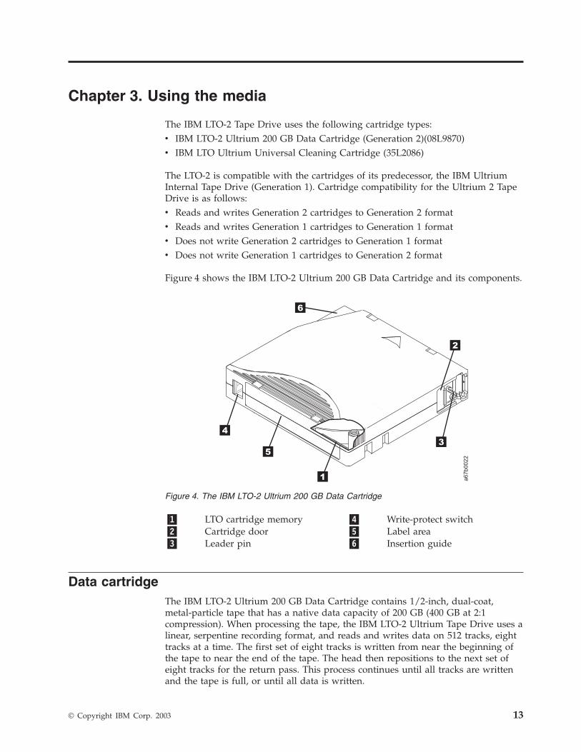
Figure 4 shows the IBM LTO-2 Ultrium 200 GB Data Cartridge and its components.
�1� LTO cartridge memory �4� Write-protect switch�2� Cartridge door �5� Label area�3� Leader pin �6� Insertion guide
Data cartridgeThe IBM LTO-2 Ultrium 200 GB Data Cartridge contains 1/2-inch, dual-coat,metal-particle tape that has a native data capacity of 200 GB (400 GB at 2:1compression). When processing the tape, the IBM LTO-2 Ultrium Tape Drive uses alinear, serpentine recording format, and reads and writes data on 512 tracks, eighttracks at a time. The first set of eight tracks is written from near the beginning ofthe tape to near the end of the tape. The head then repositions to the next set ofeight tracks for the return pass. This process continues until all tracks are writtenand the tape is full, or until all data is written.
Figure 4. The IBM LTO-2 Ultrium 200 GB Data Cartridge
© Copyright IBM Corp. 2003 13
The IBM LTO-2 Ultrium 200 GB Data Cartridge includes a Linear Tape-OpenCartridge Memory (LTO-CM) chip (�1� in Figure 4 on page 13), that containsinformation about the cartridge and the tape (such as the name of themanufacturer that created the tape), as well as statistical information about thecartridge’s use. Whenever you unload a tape cartridge, the tape drive writes anypertinent information to the cartridge memory. The storage capacity of theLTO-CM is 4096 bytes.
The cartridge door �2� protects the tape from contamination when the cartridge isout of the drive. Behind the door, the tape is attached to a leader pin �3�. Whenyou insert the cartridge into the drive, a threading mechanism pulls the pin (andtape) out of the cartridge, across the drive head, and onto a non-removable takeupreel. The head can then read or write data from or to the tape.
The write-protect switch �4� prevents data from being written to the tapecartridge. The label area �5� provides a location for you to place a label. Affix onlya bar code label. When affixing a label, place it only in the recessed label area. Alabel that extends outside of the recessed area can cause loading problems in thedrive. The insertion guide �6� is a large, notched area that prevents you frominserting the cartridge incorrectly.
The IBM LTO-2 Ultrium 200 GB Data Cartridge has a nominal cartridge life of 5000load and unload cycles. The Generation 2 cartridge is purple; the Generation 1cartridge is black.
14 IBM 200/400GB LTO-2 Tape Drive: User’s Guide

Cleaning cartridgesThe LTO-2 is compatible with the IBM LTO Ultrium Cleaning Cartridge (partnumber 08L9124) and the IBM Cleaning Cartridge (Ultrium LTO 2) (part number35L2086). Use of unsupported cleaning cartridges may void your warranty orresult in billable service charges. You can view the most current support list atwww.pc.ibm.com/support and search for ″cleaning cartridges.″
The IBM Cleaning Cartridge functions with Ultrium-format tape drives that areproduced by compliance-verified manufacturers. The cartridge lets you buy anduse a single cleaning cartridge for all of your tape drives, rather than spend timeand money to support several different cleaning cartridges.
The IBM Cleaning Cartridge (Ultrium LTO 2) is downward-compatible with theUltrium Internal Tape Drive (Generation 1). To enable your Generation 1 drive touse the cartridge, simply download and install the latest drive firmware (forinstructions, see “Updating the firmware” on page 45).
The drive itself determines when a head needs to be cleaned. It alerts you bydisplaying C on the single-character display and causing the status light to becomeflashing amber. To clean the head, insert the cleaning cartridge into the tape loadcompartment (see Figure 17 on page 34). The tape drive performs the cleaningautomatically. When the cleaning is finished, the drive ejects the cartridge.
To remove a cleaning cartridge, see “Unload button” on page 33. The IBM CleaningCartridge (Ultrium LTO 2) and the IBM LTO Ultrium Cleaning Cartridge are validfor 50 uses (the cartridge’s LTO-CM chip tracks the number of times that thecartridge is used).
Chapter 3. Using the media 15

Setting the write-protect switchThe position of the write-protect switch on the tape cartridge (see �1� in Figure 5)determines whether you can write to the tape:v If the switch is set to (solid red), data cannot be written to the tape.v If the switch is set to unlocked (black void), data can be written to the tape.
To set the switch, slide it left or right to the desired position.
Handling the cartridges
Attention: Do not insert a damaged tape cartridge into yourLTO-2. A damaged cartridge can interfere with the reliability ofthe drive and may void the warranties of the drive and thecartridge. Before inserting a tape cartridge, inspect the cartridgecase, cartridge door, and write-protect switch for breaks. If youneed to recover data from a damaged cartridge, contact yourOEM Product Application Engineer (PAE).
Incorrect handling or an incorrect environment can damage the LTO Ultrium TapeCartridge or its magnetic tape. To avoid damage to your tape cartridges and toensure the continued high reliability of your LTO-2, use the following guidelines.
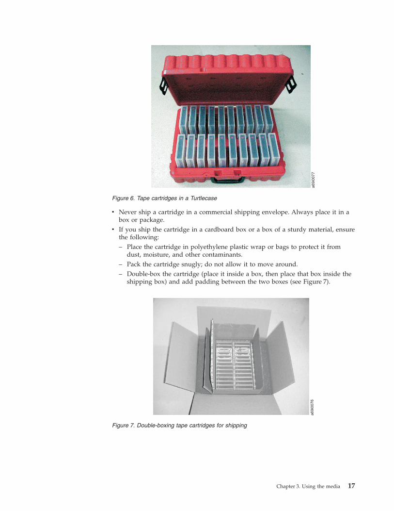
Ensure proper packagingv When you ship a cartridge, ship it in its original or better packaging.v Always ship or store a cartridge in a jewel case.v Use only a recommended shipping container that securely holds the cartridge in
its jewel case during transportation. Ultrium Turtlecases (by Perm-A-Store) havebeen tested and found to be satisfactory (see Figure 6 on page 17). They areavailable at www.turtlecase.com .
A67E
0026
1
Figure 5. Setting the write-protect switch
16 IBM 200/400GB LTO-2 Tape Drive: User’s Guide
v Never ship a cartridge in a commercial shipping envelope. Always place it in abox or package.
v If you ship the cartridge in a cardboard box or a box of a sturdy material, ensurethe following:– Place the cartridge in polyethylene plastic wrap or bags to protect it from
dust, moisture, and other contaminants.– Pack the cartridge snugly; do not allow it to move around.– Double-box the cartridge (place it inside a box, then place that box inside the
shipping box) and add padding between the two boxes (see Figure 7).
Figure 6. Tape cartridges in a Turtlecase
Figure 7. Double-boxing tape cartridges for shipping
Chapter 3. Using the media 17

Provide proper acclimation and environmental conditionsv Before you use a cartridge, let it acclimate to the normal operating environment
for 1 hour. If you see condensation on the cartridge, wait an additional hour.v Ensure that all surfaces of a cartridge are dry before inserting it.v Do not expose the cartridge to moisture or direct sunlight.v Do not expose recorded or blank cartridges to stray magnetic fields of greater
than 100 oersteds (for example, terminals, motors, video equipment, X-rayequipment, or fields that exist near high-current cables or power supplies). Suchexposure can cause the loss of recorded data or make the blank cartridgeunusable.
v Maintain the conditions that are described in “Environmental and shippingspecifications for tape cartridges” on page 27.
Perform a thorough inspectionAfter purchasing a cartridge and before using it, perform the following steps:v Inspect the cartridge’s packaging to determine potential rough handling.v When inspecting a cartridge, open only the cartridge door. Do not open any
other part of the cartridge case. The upper and lower parts of the case are heldtogether with screws; separating them destroys the usefulness of the cartridge.
v Inspect the cartridge for damage before using or storing it.v Inspect the rear of the cartridge (the part that you load first into the tape load
compartment) and ensure that there are no gaps in the seam of the cartridgecase (see �4� in Figure 9 on page 21). If there are gaps in the seam, the leader pinmay be dislodged. Go to “Repositioning or reattaching a leader pin” on page 20.
v Check that the leader pin is properly seated.v If you suspect that the cartridge has been mishandled but it appears useable,
copy any data onto a good cartridge immediately for possible data recovery.Discard the mishandled cartridge.
v If you must recover data from a damaged cartridge, contact your servicerepresentative.
v Review handling and shipping procedures.
Handle the cartridge carefullyv Do not drop the cartridge. If the cartridge drops, slide the cartridge door back
and ensure that the leader pin is properly seated in the pin-retaining spring clips(see �2� in Figure 8 on page 20). If the leader pin has become dislodged, go to“Repositioning or reattaching a leader pin” on page 20.
v Do not handle tape that is outside the cartridge. Handling the tape can damagethe tape’s surface or edges, which may interfere with read or write reliability.Pulling on tape that is outside the cartridge can damage the tape and the brakemechanism in the cartridge.
v Do not stack more than six cartridges.v Do not degauss a cartridge that you intend to reuse. Degaussing makes the tape
unusable.
18 IBM 200/400GB LTO-2 Tape Drive: User’s Guide

Examples of cartridge problemsExample: Improper placement of leader pin
The leader pin is misaligned. Perform the following steps:1. Look for cartridge damage.2. Use the IBM Leader Pin Reattachment Kit (part number 08L9129) to correctly
seat the pin (see “Repositioning a leader pin” on page 20). Then, immediatelyuse data recovery procedures to minimize chances of data loss.
Example: split cartridge case
The cartridge’s case is damaged. There is a high possibility of media damage andpotential loss. Perform the following steps:1. Look for cartridge mishandling.2. Use the IBM Leader Pin Reattachment Kit (part number 08L9129) to correctly
seat the pin (see “Repositioning a leader pin” on page 20). Then, immediatelyuse data recovery procedures to minimize chances of data loss.
3. Review media-handling procedures.
Chapter 3. Using the media 19
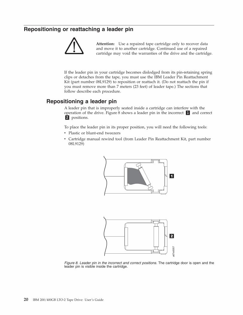
Repositioning or reattaching a leader pin
Attention: Use a repaired tape cartridge only to recover dataand move it to another cartridge. Continued use of a repairedcartridge may void the warranties of the drive and the cartridge.
If the leader pin in your cartridge becomes dislodged from its pin-retaining springclips or detaches from the tape, you must use the IBM Leader Pin ReattachmentKit (part number 08L9129) to reposition or reattach it. (Do not reattach the pin ifyou must remove more than 7 meters (23 feet) of leader tape.) The sections thatfollow describe each procedure.
Repositioning a leader pinA leader pin that is improperly seated inside a cartridge can interfere with theoperation of the drive. Figure 8 shows a leader pin in the incorrect �1� and correct�2� positions.
To place the leader pin in its proper position, you will need the following tools:v Plastic or blunt-end tweezersv Cartridge manual rewind tool (from Leader Pin Reattachment Kit, part number
08L9129)
Figure 8. Leader pin in the incorrect and correct positions. The cartridge door is open and theleader pin is visible inside the cartridge.
20 IBM 200/400GB LTO-2 Tape Drive: User’s Guide
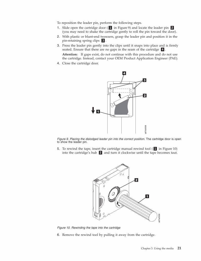
To reposition the leader pin, perform the following steps.1. Slide open the cartridge door (�1� in Figure 9) and locate the leader pin �2�
(you may need to shake the cartridge gently to roll the pin toward the door).2. With plastic or blunt-end tweezers, grasp the leader pin and position it in the
pin-retaining spring clips �3�.3. Press the leader pin gently into the clips until it snaps into place and is firmly
seated. Ensure that there are no gaps in the seam of the cartridge �4�.Attention: If gaps exist, do not continue with this procedure and do not usethe cartridge. Instead, contact your OEM Product Application Engineer (PAE).
4. Close the cartridge door.
5. To rewind the tape, insert the cartridge manual rewind tool (�1� in Figure 10)into the cartridge’s hub �2� and turn it clockwise until the tape becomes taut.
6. Remove the rewind tool by pulling it away from the cartridge.
Figure 9. Placing the dislodged leader pin into the correct position. The cartridge door is opento show the leader pin.
Figure 10. Rewinding the tape into the cartridge
Chapter 3. Using the media 21

Reattaching a leader pinThe first meter of tape in a cartridge is leader tape. Once the leader tape has beenremoved there is a possibility of tape breakage. After reattaching the leader pin,transfer data from the defective tape cartridge. Do not reuse the defective tapecartridge.
The Leader Pin Reattachment Kit contains three parts:v Leader pin attach tool (see �1� in Figure 11). A plastic brace that holds the
cartridge door open.v Cartridge manual rewind tool (see �2� in Figure 11). A device that fits into the
cartridge’s hub and lets you wind the tape into and out of the cartridge.v Pin supplies (see �3� in Figure 11). Leader pins and C-clips.
Attention:
v Use only the IBM Leader Pin Reattachment Kit to reattach the leader pin to thetape. Other methods of reattaching the pin will damage the tape, the drive, orboth.
v Use this procedure on your tape cartridge only when the leader pin detachesfrom the magnetic tape and you must copy the cartridge’s data onto anothercartridge. Destroy the damaged cartridge after you copy the data. Thisprocedure may affect the performance of the leader pin during threading andunloading operations.
v Touch only the end of the tape. Touching the tape in an area other than the endcan damage the tape’s surface or edges, which may interfere with read or writereliability.
A67E
0042
1
2
3
Figure 11. Leader Pin Reattachment Kit
22 IBM 200/400GB LTO-2 Tape Drive: User’s Guide

The following procedure describes how to reattach a leader pin.
To reattach a leader pin by using the IBM Leader Pin Reattachment Kit:1. Attach the leader pin attach tool (�1� in Figure 12) to the cartridge �2� so that
the tool’s hook �3� latches into the cartridge’s door �4�. Pull the tool back tohold the door open, then slide the tool onto the cartridge. Open the tool’spivot arm �5�.
Figure 12. Attaching the leader pin attach tool to the cartridge. To hold the cartridge dooropen, hook the tool into the door and pull the tool back.
Chapter 3. Using the media 23
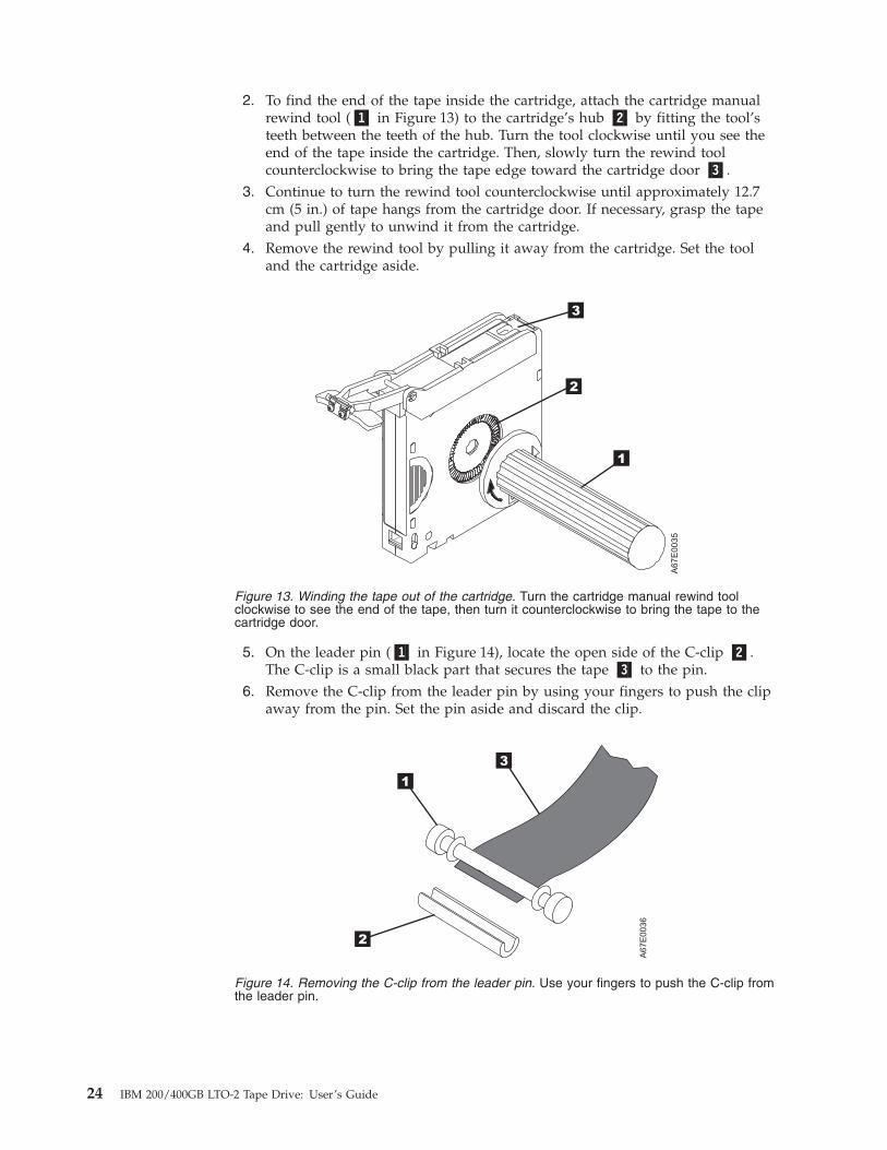
2. To find the end of the tape inside the cartridge, attach the cartridge manualrewind tool (�1� in Figure 13) to the cartridge’s hub �2� by fitting the tool’steeth between the teeth of the hub. Turn the tool clockwise until you see theend of the tape inside the cartridge. Then, slowly turn the rewind toolcounterclockwise to bring the tape edge toward the cartridge door �3�.
3. Continue to turn the rewind tool counterclockwise until approximately 12.7cm (5 in.) of tape hangs from the cartridge door. If necessary, grasp the tapeand pull gently to unwind it from the cartridge.
4. Remove the rewind tool by pulling it away from the cartridge. Set the tooland the cartridge aside.
5. On the leader pin (�1� in Figure 14), locate the open side of the C-clip �2�.The C-clip is a small black part that secures the tape �3� to the pin.
6. Remove the C-clip from the leader pin by using your fingers to push the clipaway from the pin. Set the pin aside and discard the clip.
Figure 13. Winding the tape out of the cartridge. Turn the cartridge manual rewind toolclockwise to see the end of the tape, then turn it counterclockwise to bring the tape to thecartridge door.
A67E
0036
1
2
3
Figure 14. Removing the C-clip from the leader pin. Use your fingers to push the C-clip fromthe leader pin.
24 IBM 200/400GB LTO-2 Tape Drive: User’s Guide

7. Position the tape in the alignment groove of the leader pin attach tool (see �1�in Figure 15).
8. Place a new C-clip into the retention groove �2� (Figure 15) on the leader pinattachment tool and make sure that the clip’s open side faces up.
9. Place the leader pin (from step 6 on page 24) into the cavity �3� (Figure 15) ofthe leader pin attach tool.
Attention: To prevent the leader pin from rolling into the cartridge, in thefollowing step use care when folding the tape over the pin.10. Fold the tape over the leader pin and hold it with your fingers (see Figure 15).
Note: Use care to ensure that the tape is centered over the leader pin. Failureto properly center the tape on the pin will cause the repaired cartridgeto fail. When the tape is properly centered, a 0.25-mm (0.01-in.) gapexists on both sides of the pin.
11. Close the pivot arm �4� of the leader pin attach tool by swinging it over theleader pin so that the C-clip snaps onto the pin and the tape.
12. Swing the pivot arm open and trim the excess tape �5� so that it is flush withthe reattached leader pin �6�.
A67E
0037
1
6
2
3
4
5
Figure 15. Attaching the leader pin to the tape
Chapter 3. Using the media 25
13. Use your fingers to remove the leader pin from the cavity �3� in the leaderpin attach tool.
14. Use the cartridge manual rewind tool to wind the tape back into the cartridge(wind the tape clockwise). Ensure that the leader pin is latched by thepin-retaining spring clips on each end of the leader pin.
15. Remove the rewind tool.16. Remove the leader pin attach tool by lifting its end up and away from the
cartridge.
Attention: Use a repaired tape cartridge only to recover dataand move it to another cartridge. Continued use of a repairedcartridge may void the warranties of the drive and the cartridge.
26 IBM 200/400GB LTO-2 Tape Drive: User’s Guide

Environmental and shipping specifications for tape cartridgesBefore you use a tape cartridge, acclimate it to the operating environment for 24hours or the time necessary to prevent condensation in the drive (the time willvary, depending on the environmental extremes to which the drive was exposed).
The best storage container for the cartridges (until they are opened) is the originalshipping container. The plastic wrapping prevents dirt from accumulating on thecartridges and partially protects them from humidity changes.
When you ship a cartridge, place it in its jewel case or in a sealed, moisture-proofbag to protect it from moisture, contaminants, and physical damage. Ship thecartridge in a shipping container that has enough packing material to cushion thecartridge and prevent it from moving within the container.
Table 1 gives the environment for operating, storing, and shipping LTO UltriumTape Cartridges.
Table 1. Environment for operating, storing, and shipping the LTO Ultrium Tape Cartridge
Environmental Specifications
Environmental Factor Operating Operational Storage1 Archival Storage2 Shipping
Temperature10 to 45°C
(50 to 113°F)
16 to 32°C
(61 to 90°F)
16 to 25°C
(61 to 77°F)
−23 to 49°C
(−9 to 120°F)
Relative humidity(noncondensing)
10 to 80% 20 to 80% 20 to 50% 5 to 80%
Wet bulb temperature26°C
(79°F)
26°C
(79°F)
26°C
(79°F)
26°C
(79°F)
Notes:
1. Operational storage equals less than 1 year.
2. Archival storage equals 1 to 10 years.
Chapter 3. Using the media 27

Disposing of tape cartridgesUnder the current rules of the U.S. Environmental Protection Agency (EPA),regulation 40CFR261, the LTO Ultrium Tape Cartridge is classified asnon-hazardous waste. As such, it may be disposed of in the same way as normaloffice trash. These regulations are amended from time to time, and you shouldreview them at the time of disposal.
If your local, state, country (non-U.S.A.), or regional regulations are morerestrictive than EPA 40CFR261, you must review them before you dispose of acartridge. Contact your account representative for information about the materialsthat are in the cartridge.
If a tape cartridge must be disposed of in a secure manner, you can erase the dataon the cartridge by using a high-energy AC degausser (use a minimum of 1200oersted peak field over the entire space that the cartridge occupies). Degaussingmakes the cartridge unusable.
If you burn the cartridge and tape, ensure that the incineration complies with allapplicable regulations.
Ordering media suppliesTable 2 lists the cartridges and media supplies that you can order for the IBMLTO-2 Ultrium 2 Tape Drive. To order media supplies, visit the web atwww.ibm.com/storage/lto.
Table 2. Media supplies for the IBM LTO-2 Ultrium 2 Tape Drive
IBM Part Number Product Description
08L9870IBM LTO-2 Ultrium 200 GB Data Cartridge (includes onlyhuman-writable labels)
19P5897IBM LTO-2 Ultrium 200 GB Data Cartridge Bar Code Labels, sheet of20, black and white
08L9124IBM LTO Ultrium Cleaning Cartridge (includes only human-writablelabels)
35L2086 IBM Cleaning Cartridge (Ultrium LTO 2)
08L9267IBM LTO Ultrium Cleaning Cartridge Bar Code Labels, sheet of 20,black and white
28 IBM 200/400GB LTO-2 Tape Drive: User’s Guide

Ordering custom bar code labelsIf custom bar code labels are required for your data or cleaning cartridges, orderthem directly from the authorized label suppliers in Table 3.
Table 3. Authorized suppliers of custom bar code labels
In America In Europe and Asia
EDP/Colorflex697 South Pierce StreetLouisville, CO 80027U. S. A.Telephone: 800-522-3528www.colorflex.com/Ai/Home.asp
EDP Europe, Ltd.43 Redhills RoadSouth Woodham FerrersChelmsford, Essex CM3 5ULU. K.Telephone: 44 (0) 1245-322380www.edpeurope.com/media_labelling.htm
Dataware (LTO 2 only)7570 RenwickHouston, TX 77081U. S. A.Telephone: 800-426-4844www.datawarelabels.com/
Dataware Labels EuropeHeubergstrasse 9D-83052 Bruckmuhl-GottingGermanyTelephone: 49 806-29455www.datawarelabels.com/
NetCP. O. Box 320784Fairfield, CT 06432U. S. A.Telephone: 203-372-6382www.netcllc.com/
NetC Europe LtdTown Farm BungalowNorth CurryTauntonSomerset U. K. TA3 6LXTelephone: 44 (0) 1823 491439www.netclabels.co.uk
NetC Asia Pacific Pty LtdLocked Bag 14KenthurstNSW Australia 2156Telephone: 61 (0) 2 9654 8272www.netclabels.com.au
Chapter 3. Using the media 29

30 IBM 200/400GB LTO-2 Tape Drive: User’s Guide

Chapter 4. Operating the tape drive
When operating the LTO-2, refer to Figure 16 which shows the front of the unit.
�1� Status light
�2� Unload button
�3� Single-character display
�4� Single red dot
Figure 16. Front view of the IBM LTO-2 Tape Drive
© Copyright IBM Corp. 2003 31
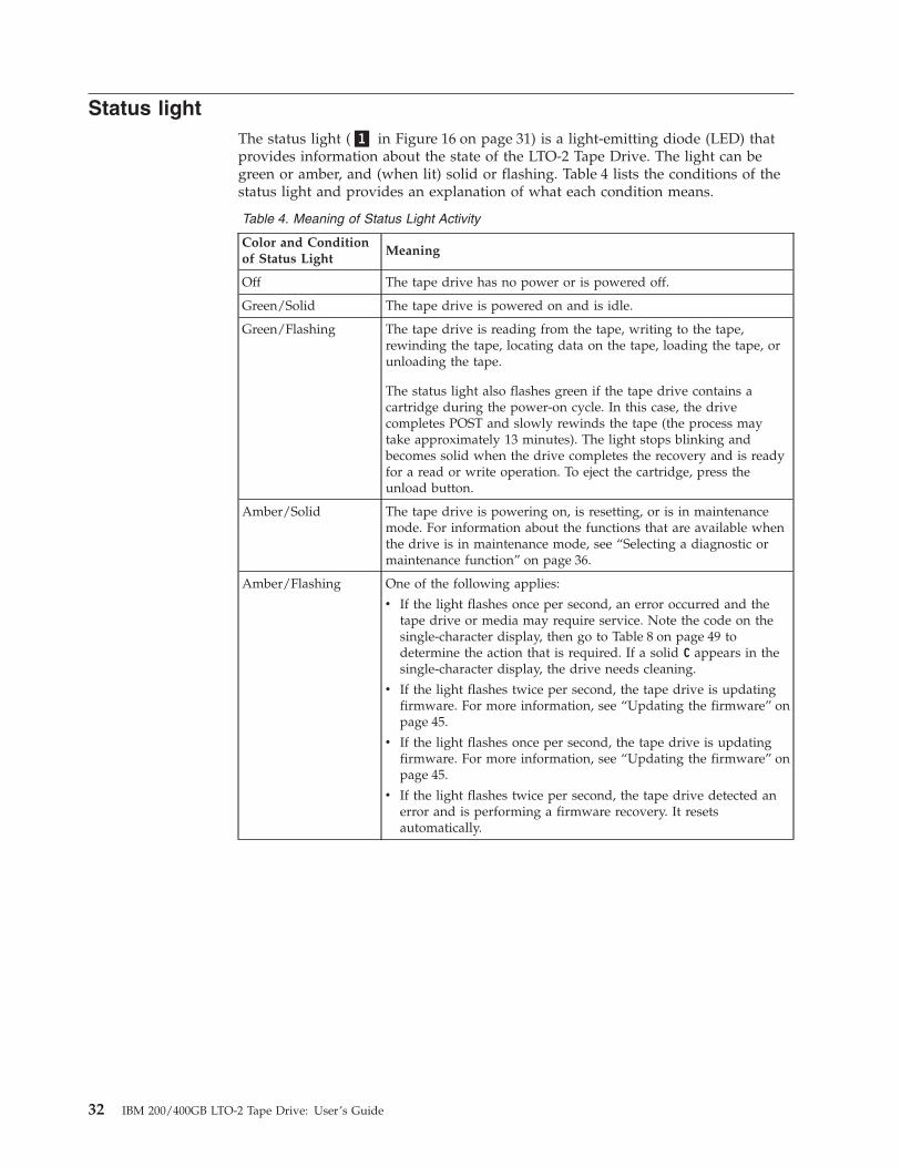
Status lightThe status light (�1� in Figure 16 on page 31) is a light-emitting diode (LED) thatprovides information about the state of the LTO-2 Tape Drive. The light can begreen or amber, and (when lit) solid or flashing. Table 4 lists the conditions of thestatus light and provides an explanation of what each condition means.
Table 4. Meaning of Status Light Activity
Color and Conditionof Status Light
Meaning
Off The tape drive has no power or is powered off.
Green/Solid The tape drive is powered on and is idle.
Green/Flashing The tape drive is reading from the tape, writing to the tape,rewinding the tape, locating data on the tape, loading the tape, orunloading the tape.
The status light also flashes green if the tape drive contains acartridge during the power-on cycle. In this case, the drivecompletes POST and slowly rewinds the tape (the process maytake approximately 13 minutes). The light stops blinking andbecomes solid when the drive completes the recovery and is readyfor a read or write operation. To eject the cartridge, press theunload button.
Amber/Solid The tape drive is powering on, is resetting, or is in maintenancemode. For information about the functions that are available whenthe drive is in maintenance mode, see “Selecting a diagnostic ormaintenance function” on page 36.
Amber/Flashing One of the following applies:
v If the light flashes once per second, an error occurred and thetape drive or media may require service. Note the code on thesingle-character display, then go to Table 8 on page 49 todetermine the action that is required. If a solid C appears in thesingle-character display, the drive needs cleaning.
v If the light flashes twice per second, the tape drive is updatingfirmware. For more information, see “Updating the firmware” onpage 45.
v If the light flashes once per second, the tape drive is updatingfirmware. For more information, see “Updating the firmware” onpage 45.
v If the light flashes twice per second, the tape drive detected anerror and is performing a firmware recovery. It resetsautomatically.
32 IBM 200/400GB LTO-2 Tape Drive: User’s Guide

Unload buttonThe unload button (�2� in Figure 16 on page 31) enables you to perform thefollowing functions:v Rewind the tape into the cartridge and eject the cartridge from the tape drive.
For more information, see “Removing a tape cartridge” on page 35.v Enter or exit maintenance mode, or perform diagnostic or maintenance
functions. For more information, see “Selecting a diagnostic or maintenancefunction” on page 36.
v Perform a panic reset of the drive. Attention: If the tape drive detected apermanent error and displayed an error code, it automatically forces a drivedump (also known as a save of the firmware trace). If you perform a panic resetof the drive, the existing dump will be overwritten and lost. To perform a panicreset, press and hold the unload button on the drive for 10 seconds. The driveforces a dump and overwrites the existing dump. The drive then reboots toallow communication.
Single-character displayThe LTO-2 features an LED (�3� in Figure 16 on page 31) that presents asingle-character code for:v Diagnostic or maintenance functionsv Error conditions and informational messages
Table 5 on page 36 lists each single-character code that is used for diagnostic ormaintenance functions. Table 8 on page 49 lists the codes for error conditions andinformational messages. If multiple errors occur, the code with the highest priority(represented by the lowest number) displays first. When the error is corrected, thecode with the next highest priority displays, and so on until no errors remain.
Single red dotThe single-character display is blank during normal operation. However, if a drivedump is present while the drive is in maintenance mode, a single red dotilluminates on the display. To copy the dump to tape, see Function Code 5 inTable 5 on page 36.
The red dot turns off when you obtain the dump (by using an FMR tape or a SCSIcommand). If no dump is present while the drive is in maintenance mode, thesingle red dot does not illuminate.
Chapter 4. Operating the tape drive 33

Inserting a tape cartridgeTo insert a tape cartridge:1. Ensure that the LTO-2 is powered-on.2. Ensure that the write-protect switch is properly set (see “Setting the
write-protect switch” on page 16).3. Grasp the cartridge so that the write-protect switch faces you (see �1� in
Figure 17).4. Slide the cartridge into the tape load compartment.
Notes:
a. If the cartridge is already in an ejected position and you want to reinsert it,remove the cartridge then insert it again.
b. If the cartridge is already loaded and you cycle the power (turn it off, thenon), the tape will reload.
Figure 17. Inserting a cartridge into the LTO-2
34 IBM 200/400GB LTO-2 Tape Drive: User’s Guide

Removing a tape cartridgeTo remove a tape cartridge:1. Ensure that the LTO-2 is powered-on.2. Press the unload button. The drive rewinds the tape and partially ejects the
cartridge. The status light flashes green while the tape rewinds, then goes outbefore the cartridge partially ejects.
3. After the cartridge partially ejects, grasp the cartridge and remove it.
If you are unable to remove the cartridge, see “Manually removing a tapecartridge” on page 58. Whenever you unload a tape cartridge, the tape drive writesany pertinent information to the cartridge memory.
Cleaning the drive headAttention: To clean the drive head, use the IBM 35L2086 LTO Ultrium CleaningCartridge.
Note: You must use only IBM supported cleaning cartridges. Use of unsupportedcleaning cartridges may void your warranty or result in billable servicecharges. You can view the most current support list atwww.pc.ibm.com/support and search for ″cleaning cartridges.″
Clean the drive head whenever C displays on the single-character display and thestatus light is flashing amber. To clean the head, insert the cleaning cartridge intothe tape load compartment (see Figure 17 on page 34). The drive performs thecleaning automatically. When the cleaning is finished, the drive ejects the cartridge.Most universal cleaning cartridges are generally valid for 50 cleanings.
Chapter 4. Operating the tape drive 35

Selecting a diagnostic or maintenance functionThe LTO-2 can run diagnostics, test write and read functions, test a suspect tapecartridge, update its own firmware, and perform other diagnostic and maintenancefunctions. The drive must be in maintenance mode to perform these functions. Toplace the drive in maintenance mode and select a diagnostic or maintenancefunction, see Table 5.
Attention: Maintenance functions cannot be performed concurrently with read orwrite operations. While in maintenance mode, the tape drive does not accept SCSIcommands from the server.
Note: For best results, Function Codes 2-7 should be performed by IBM qualifiedservice persons. Otherwise, perform these codes only when instructed to doso by IBM service or support.
Table 5. Diagnostic and maintenance functions
Function Code 1 - Run SCSI Drive Diagnostics
Causes the tape drive to run self tests.
Attention: Insert only a scratch data cartridge for this test. Data on the cartridge will be overwritten.
1. Make sure that no cartridge is in the drive.
2. Within a 1.5-second interval, press the unload button three times. The status light becomes solid amber, whichmeans that the drive is in maintenance mode.
3. Press the unload button once per 1.5 seconds until 1 appears in the single-character display. If you cycle past 1,continue to press the unload button until it redisplays.
4. To select the function, press and hold the unload button for 3 seconds. After you select the function, 1 flashes,the drive runs diagnostics for approximately 90 seconds, then C flashes. When C flashes, the drive is waiting fora cartridge.
5. Within 60 seconds, insert a scratch data cartridge (or the tape drive exits maintenance mode). After you insertthe cartridge, 1 flashes:
v If the diagnostic completes successfully, it begins again and runs for a maximum of 10 times. Each loop takesapproximately 20 minutes to run. After the tenth loop, the diagnostic stops and automatically exitsmaintenance mode. To halt the diagnostic, press the unload button within the first 20 minutes of the test (orthe diagnostic will run another 20 minutes). The drive acknowledges the request by slowing the length of timethat the currently displayed character flashes on the single-character display (from twice per second to onceper second). The diagnostic continues to the end of its loop and then stops. The tape drive then displays 0,rewinds and unloads the cartridge, and exits maintenance mode.
v If the diagnostics fail, the status light flashes amber and an error code displays. The tape drive unloads thetape cartridge and exits maintenance mode. To resolve the error, locate the code in Table 8 on page 49.
36 IBM 200/400GB LTO-2 Tape Drive: User’s Guide
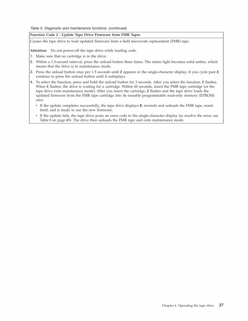
Table 5. Diagnostic and maintenance functions (continued)
Function Code 2 - Update Tape Drive Firmware from FMR Tapes
Causes the tape drive to load updated firmware from a field microcode replacement (FMR) tape.
Attention: Do not power-off the tape drive while loading code.
1. Make sure that no cartridge is in the drive.
2. Within a 1.5-second interval, press the unload button three times. The status light becomes solid amber, whichmeans that the drive is in maintenance mode.
3. Press the unload button once per 1.5 seconds until 2 appears in the single-character display. If you cycle past 2,continue to press the unload button until it redisplays.
4. To select the function, press and hold the unload button for 3 seconds. After you select the function, C flashes.When C flashes, the drive is waiting for a cartridge. Within 60 seconds, insert the FMR tape cartridge (or thetape drive exits maintenance mode). After you insert the cartridge, 2 flashes and the tape drive loads theupdated firmware from the FMR tape cartridge into its erasable programmable read-only memory (EPROM)area:
v If the update completes successfully, the tape drive displays 0, rewinds and unloads the FMR tape, resetsitself, and is ready to use the new firmware.
v If the update fails, the tape drive posts an error code to the single-character display (to resolve the error, seeTable 8 on page 49). The drive then unloads the FMR tape and exits maintenance mode.
Chapter 4. Operating the tape drive 37
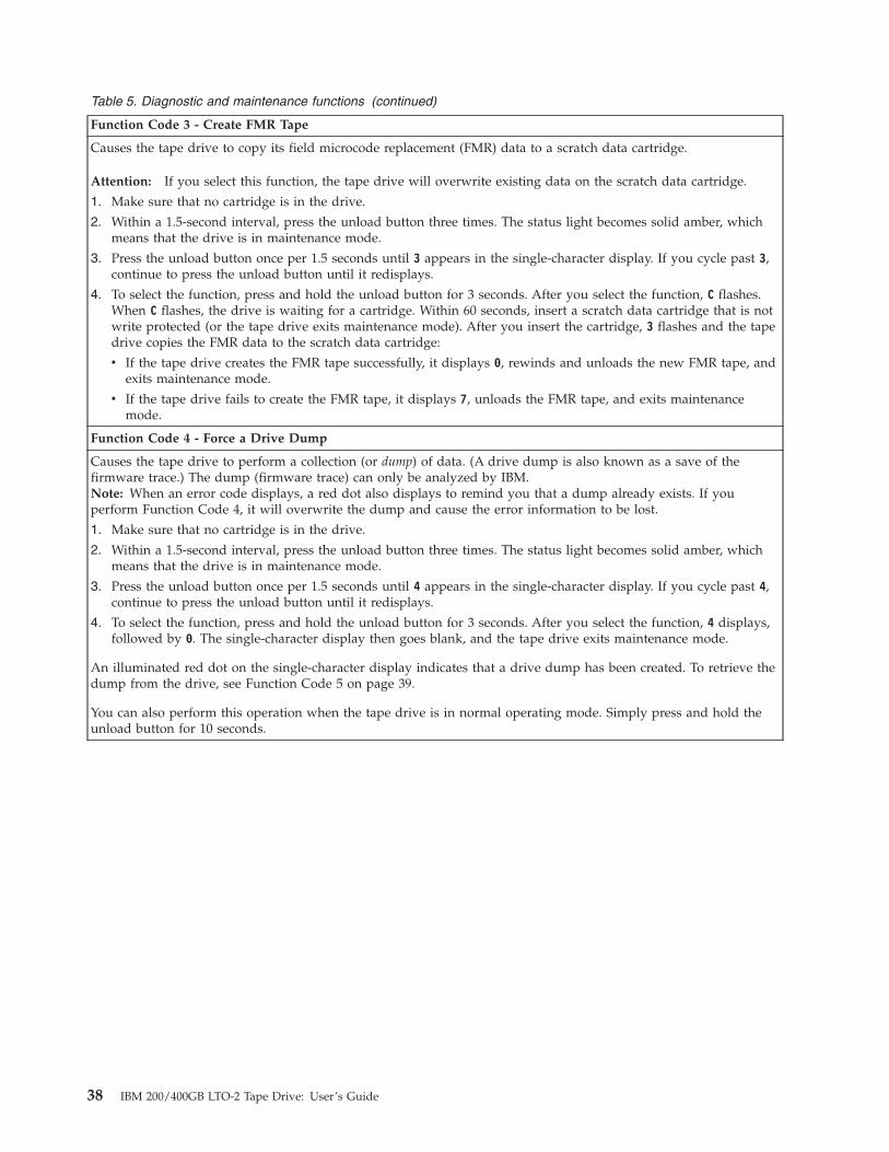
Table 5. Diagnostic and maintenance functions (continued)
Function Code 3 - Create FMR Tape
Causes the tape drive to copy its field microcode replacement (FMR) data to a scratch data cartridge.
Attention: If you select this function, the tape drive will overwrite existing data on the scratch data cartridge.
1. Make sure that no cartridge is in the drive.
2. Within a 1.5-second interval, press the unload button three times. The status light becomes solid amber, whichmeans that the drive is in maintenance mode.
3. Press the unload button once per 1.5 seconds until 3 appears in the single-character display. If you cycle past 3,continue to press the unload button until it redisplays.
4. To select the function, press and hold the unload button for 3 seconds. After you select the function, C flashes.When C flashes, the drive is waiting for a cartridge. Within 60 seconds, insert a scratch data cartridge that is notwrite protected (or the tape drive exits maintenance mode). After you insert the cartridge, 3 flashes and the tapedrive copies the FMR data to the scratch data cartridge:
v If the tape drive creates the FMR tape successfully, it displays 0, rewinds and unloads the new FMR tape, andexits maintenance mode.
v If the tape drive fails to create the FMR tape, it displays 7, unloads the FMR tape, and exits maintenancemode.
Function Code 4 - Force a Drive Dump
Causes the tape drive to perform a collection (or dump) of data. (A drive dump is also known as a save of thefirmware trace.) The dump (firmware trace) can only be analyzed by IBM.Note: When an error code displays, a red dot also displays to remind you that a dump already exists. If youperform Function Code 4, it will overwrite the dump and cause the error information to be lost.
1. Make sure that no cartridge is in the drive.
2. Within a 1.5-second interval, press the unload button three times. The status light becomes solid amber, whichmeans that the drive is in maintenance mode.
3. Press the unload button once per 1.5 seconds until 4 appears in the single-character display. If you cycle past 4,continue to press the unload button until it redisplays.
4. To select the function, press and hold the unload button for 3 seconds. After you select the function, 4 displays,followed by 0. The single-character display then goes blank, and the tape drive exits maintenance mode.
An illuminated red dot on the single-character display indicates that a drive dump has been created. To retrieve thedump from the drive, see Function Code 5 on page 39.
You can also perform this operation when the tape drive is in normal operating mode. Simply press and hold theunload button for 10 seconds.
38 IBM 200/400GB LTO-2 Tape Drive: User’s Guide

Table 5. Diagnostic and maintenance functions (continued)
Function Code 5 - Copy the Drive Dump to Tape (at Beginning of Tape)
Causes the tape drive to copy data from a drive dump (captured with Function Code 4) to the beginning of ascratch data cartridge. An illuminated red dot on the single-character display indicates that a drive dump has beencreated.
1. Make sure that no cartridge is in the drive.
2. Within a 1.5-second interval, press the unload button three times. The status light becomes solid amber, whichmeans that the drive is in maintenance mode.
3. Press the unload button once per 1.5 seconds until 5 appears in the single-character display. If you cycle past 5,continue to press the unload button until it redisplays.
4. To select the function, press and hold the unload button for 3 seconds. After you select the function, C flashes.When C flashes, the drive is waiting for a cartridge. Within 60 seconds, insert a scratch data cartridge that is notwrite-protected (or the tape drive exits maintenance mode). After you insert the cartridge, 5 flashes and the tapedrive writes the dump data to the tape (at the beginning of the tape). When the function is complete, 0 displays,the drive rewinds and unloads the tape, and exits maintenance mode.
From the server, issue the SCSI READ command to read the dump from the tape to a file or electronic image.For information about where to send the electronic image, contact your OEM Product Application Engineer(PAE).
Function Code 6 - Run SCSI Wrap Test
Causes the drive to perform a check of the SCSI circuitry from and to the SCSI connector.
To run the test, perform the following procedure.
Running a SCSI Wrap Test
This test evaluates the SCSI circuitry. A SCSI LVD wrap plug, a SCSI LVD terminator, and a Y-cable are required forthis procedure.Note: You can terminate the Generation 1 drive internally while running the SCSI wrap test. Internal termination isnot built into the Generation 2 drive, therefore you must run the SCSI wrap test by using a Y-cable and externaltermination.
Before you select this function, you must configure the drive to supply term power, terminate the SCSI bus, andattach the SCSI wrap plug. Configure the drive to supply term power by placing a jumper on pin 6 of the drive’sSCSI ID connector (as shown by the shaded area in the figure below).
A67E
0049
Connect a Y-cable to the drive’s SCSI connector. Place a terminator on one end of the Y-cable and the wrap plug onthe other end.
1. Ensure that the drive does not contain a cartridge.
2. Within a 1.5-second interval, press the unload button three times. The status light becomes solid amber, whichmeans that the drive is in maintenance mode.
3. Press the unload button once per 1.5 seconds until 6 appears in the single-character display. If you cycle past 6,continue to press the unload button until it redisplays.
4. To select the function, press and hold the unload button for 3 seconds. After you select the function, the tapedrive automatically starts the test:
v If the test is successful, it loops and begins again. To halt the test, press the unload button. The driveacknowledges the request by slowing the length of time that the currently displayed character flashes on thesingle-character display (from twice per second to once per second). The test continues to the end of its loop,then stops. 0 displays and the drive exits maintenance mode. To continue to isolate the problem, go to “FixingSCSI bus errors” on page 53 and locate the steps to take after you run the SCSI wrap test.
v If the test fails, 8 displays, the test stops, and the tape drive exits maintenance mode. To resolve the error,replace the tape drive (see “Removing a SCSI tape drive from an enclosure” on page 57).
Chapter 4. Operating the tape drive 39
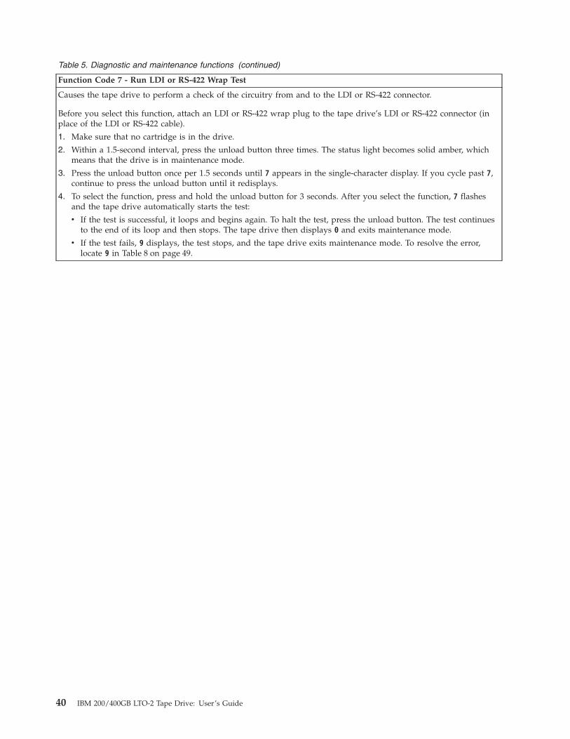
Table 5. Diagnostic and maintenance functions (continued)
Function Code 7 - Run LDI or RS-422 Wrap Test
Causes the tape drive to perform a check of the circuitry from and to the LDI or RS-422 connector.
Before you select this function, attach an LDI or RS-422 wrap plug to the tape drive’s LDI or RS-422 connector (inplace of the LDI or RS-422 cable).
1. Make sure that no cartridge is in the drive.
2. Within a 1.5-second interval, press the unload button three times. The status light becomes solid amber, whichmeans that the drive is in maintenance mode.
3. Press the unload button once per 1.5 seconds until 7 appears in the single-character display. If you cycle past 7,continue to press the unload button until it redisplays.
4. To select the function, press and hold the unload button for 3 seconds. After you select the function, 7 flashesand the tape drive automatically starts the test:
v If the test is successful, it loops and begins again. To halt the test, press the unload button. The test continuesto the end of its loop and then stops. The tape drive then displays 0 and exits maintenance mode.
v If the test fails, 9 displays, the test stops, and the tape drive exits maintenance mode. To resolve the error,locate 9 in Table 8 on page 49.
40 IBM 200/400GB LTO-2 Tape Drive: User’s Guide

Table 5. Diagnostic and maintenance functions (continued)
Function Code 8 - Convert FMR Tape to Scratch Tape
Causes the tape drive to erase the field microcode replacement (FMR) data on a scratch data cartridge and rewritethe cartridge memory on the tape. This turns the cartridge into a valid scratch data cartridge.
1. Make sure that no cartridge is in the drive.
2. Within a 1.5-second interval, press the unload button three times. The status light becomes solid amber, whichmeans that the drive is in maintenance mode.
3. Press the unload button once per 1.5 seconds until 8 appears in the single-character display. If you cycle past 8,continue to press the unload button until it redisplays.
4. To select the function, press and hold the unload button for 3 seconds. After you select the function, C flashes.When C flashes, the drive is waiting for a cartridge. Within 60 seconds, insert the FMR cartridge (or the tapedrive exits maintenance mode). After you insert the cartridge, 8 flashes, the tape drive erases the firmware onthe tape, then rewrites the header in the cartridge memory to change the cartridge to a valid scratch datacartridge:
v If the operation is successful, the tape drive displays 0, rewinds and ejects the newly converted scratch datacartridge, and exits maintenance mode.
v If the operation is not successful, an error code displays. To resolve the error, locate the code in Table 8 onpage 49.
Function Code 9 - Display Error Code Log
Causes the tape drive to display the last 10 error codes, one at a time (the codes are ordered; the most recent ispresented first and the oldest (tenth) is presented last).
1. Make sure that no cartridge is in the drive.
2. Within a 1.5-second interval, press the unload button three times. The status light becomes solid amber, whichmeans that the drive is in maintenance mode.
3. Press the unload button once per 1.5 seconds until 9 appears in the single-character display. If you cycle past 9,continue to press the unload button until it redisplays.
4. To select the function, press and hold the unload button for 3 seconds. After you select the function, press theunload button to view the most recent error code. Press the unload button again to view successive error codes.If you press the unload button for 3 seconds after the tenth error code displays, 0 displays (if there are no errorsin the log) and the drive exits maintenance mode.
Chapter 4. Operating the tape drive 41
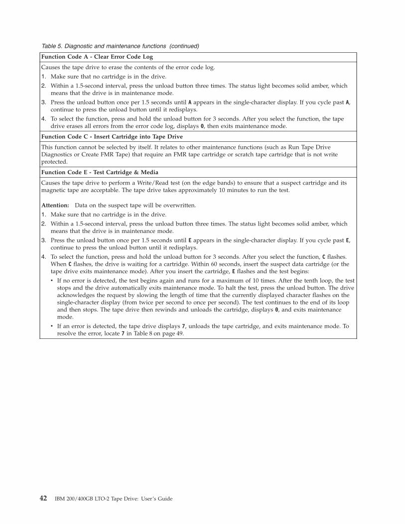
Table 5. Diagnostic and maintenance functions (continued)
Function Code A - Clear Error Code Log
Causes the tape drive to erase the contents of the error code log.
1. Make sure that no cartridge is in the drive.
2. Within a 1.5-second interval, press the unload button three times. The status light becomes solid amber, whichmeans that the drive is in maintenance mode.
3. Press the unload button once per 1.5 seconds until A appears in the single-character display. If you cycle past A,continue to press the unload button until it redisplays.
4. To select the function, press and hold the unload button for 3 seconds. After you select the function, the tapedrive erases all errors from the error code log, displays 0, then exits maintenance mode.
Function Code C - Insert Cartridge into Tape Drive
This function cannot be selected by itself. It relates to other maintenance functions (such as Run Tape DriveDiagnostics or Create FMR Tape) that require an FMR tape cartridge or scratch tape cartridge that is not writeprotected.
Function Code E - Test Cartridge & Media
Causes the tape drive to perform a Write/Read test (on the edge bands) to ensure that a suspect cartridge and itsmagnetic tape are acceptable. The tape drive takes approximately 10 minutes to run the test.
Attention: Data on the suspect tape will be overwritten.
1. Make sure that no cartridge is in the drive.
2. Within a 1.5-second interval, press the unload button three times. The status light becomes solid amber, whichmeans that the drive is in maintenance mode.
3. Press the unload button once per 1.5 seconds until E appears in the single-character display. If you cycle past E,continue to press the unload button until it redisplays.
4. To select the function, press and hold the unload button for 3 seconds. After you select the function, C flashes.When C flashes, the drive is waiting for a cartridge. Within 60 seconds, insert the suspect data cartridge (or thetape drive exits maintenance mode). After you insert the cartridge, E flashes and the test begins:
v If no error is detected, the test begins again and runs for a maximum of 10 times. After the tenth loop, the teststops and the drive automatically exits maintenance mode. To halt the test, press the unload button. The driveacknowledges the request by slowing the length of time that the currently displayed character flashes on thesingle-character display (from twice per second to once per second). The test continues to the end of its loopand then stops. The tape drive then rewinds and unloads the cartridge, displays 0, and exits maintenancemode.
v If an error is detected, the tape drive displays 7, unloads the tape cartridge, and exits maintenance mode. Toresolve the error, locate 7 in Table 8 on page 49.
42 IBM 200/400GB LTO-2 Tape Drive: User’s Guide
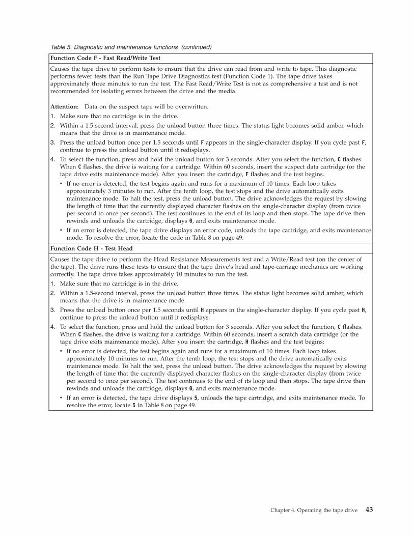
Table 5. Diagnostic and maintenance functions (continued)
Function Code F - Fast Read/Write Test
Causes the tape drive to perform tests to ensure that the drive can read from and write to tape. This diagnosticperforms fewer tests than the Run Tape Drive Diagnostics test (Function Code 1). The tape drive takesapproximately three minutes to run the test. The Fast Read/Write Test is not as comprehensive a test and is notrecommended for isolating errors between the drive and the media.
Attention: Data on the suspect tape will be overwritten.
1. Make sure that no cartridge is in the drive.
2. Within a 1.5-second interval, press the unload button three times. The status light becomes solid amber, whichmeans that the drive is in maintenance mode.
3. Press the unload button once per 1.5 seconds until F appears in the single-character display. If you cycle past F,continue to press the unload button until it redisplays.
4. To select the function, press and hold the unload button for 3 seconds. After you select the function, C flashes.When C flashes, the drive is waiting for a cartridge. Within 60 seconds, insert the suspect data cartridge (or thetape drive exits maintenance mode). After you insert the cartridge, F flashes and the test begins.
v If no error is detected, the test begins again and runs for a maximum of 10 times. Each loop takesapproximately 3 minutes to run. After the tenth loop, the test stops and the drive automatically exitsmaintenance mode. To halt the test, press the unload button. The drive acknowledges the request by slowingthe length of time that the currently displayed character flashes on the single-character display (from twiceper second to once per second). The test continues to the end of its loop and then stops. The tape drive thenrewinds and unloads the cartridge, displays 0, and exits maintenance mode.
v If an error is detected, the tape drive displays an error code, unloads the tape cartridge, and exits maintenancemode. To resolve the error, locate the code in Table 8 on page 49.
Function Code H - Test Head
Causes the tape drive to perform the Head Resistance Measurements test and a Write/Read test (on the center ofthe tape). The drive runs these tests to ensure that the tape drive’s head and tape-carriage mechanics are workingcorrectly. The tape drive takes approximately 10 minutes to run the test.
1. Make sure that no cartridge is in the drive.
2. Within a 1.5-second interval, press the unload button three times. The status light becomes solid amber, whichmeans that the drive is in maintenance mode.
3. Press the unload button once per 1.5 seconds until H appears in the single-character display. If you cycle past H,continue to press the unload button until it redisplays.
4. To select the function, press and hold the unload button for 3 seconds. After you select the function, C flashes.When C flashes, the drive is waiting for a cartridge. Within 60 seconds, insert a scratch data cartridge (or thetape drive exits maintenance mode). After you insert the cartridge, H flashes and the test begins:
v If no error is detected, the test begins again and runs for a maximum of 10 times. Each loop takesapproximately 10 minutes to run. After the tenth loop, the test stops and the drive automatically exitsmaintenance mode. To halt the test, press the unload button. The drive acknowledges the request by slowingthe length of time that the currently displayed character flashes on the single-character display (from twiceper second to once per second). The test continues to the end of its loop and then stops. The tape drive thenrewinds and unloads the cartridge, displays 0, and exits maintenance mode.
v If an error is detected, the tape drive displays 5, unloads the tape cartridge, and exits maintenance mode. Toresolve the error, locate 5 in Table 8 on page 49.
Chapter 4. Operating the tape drive 43

Table 5. Diagnostic and maintenance functions (continued)
Function Code L - Reserved for Future Use
Reserved for future use.
Function Code P or U - Enable or Disable Post Error Reporting
Used by support personnel during error detection, this function is an alternate method of setting or preventing thepost error (PER) bit in the SCSI Read-Write Error Recovery Page. For more information, refer to the MODE SENSEcommand in the IBM LTO-2 Ultrium Tape Drive SCSI Reference.
1. Make sure that no cartridge is in the drive.
2. Within a 1.5-second interval, press the unload button three times. The status light becomes solid amber, whichmeans that the drive is in maintenance mode.
3. Perform one of the following:
v To enable post error reporting, press the unload button once per 1.5 seconds until U appears in thesingle-character display. If you cycle past U, continue to press the unload button until it redisplays.
v To disable post error reporting, press the unload button once per 1.5 seconds until P appears in thesingle-character display. If you cycle past P, continue to press the unload button until it redisplays.
4. To select the function, press and hold the unload button for 3 seconds. After you select the function, the drivedisplays one of the following:
v P to indicate that post error reporting is enabled.
v U to indicate that post error reporting is disabled.
44 IBM 200/400GB LTO-2 Tape Drive: User’s Guide

Exiting maintenance modeTo manually exit maintenance mode, press the unload button once per second until0 appears on the single-character display. Press and hold the unload button for 3seconds. The drive exits maintenance mode (the solid amber status light becomessolid green, then turns off).
You can also exit maintenance mode by pressing the unload button during anymaintenance or diagnostic function.
Updating the firmwareAttention: When updating firmware, do not power-off the tape drive until theupdate is complete, or the firmware may be lost.
Periodically check for updated levels of drive firmware by visiting the web atwww.pc.ibm.com/support and search for 59P6744. You can update your drive’sfirmware by:v Obtaining the new firmware image and downloading it to the drive through the
SCSI interfacev Downloading the Firmware Update CD from IBM at www.pc.ibm.com/support.
For instructions about how to obtain a new firmware image or FMR tape, visit thepreceding Web site. The preceding Web site includes instructions for downloadingfirmware or obtaining a Firmware Update CD.
Chapter 4. Operating the tape drive 45

46 IBM 200/400GB LTO-2 Tape Drive: User’s Guide

Chapter 5. Resolving problems
If you encounter problems when running the LTO-2 Tape Drive, refer to Table 6. Ifthe problem is not identified in Table 6, refer to “Methods of receiving errors andmessages”. The color and condition of the status light may also indicate a problem.For more information, see “Status light” on page 32.
Table 6. Troubleshooting tips for the IBM 200/400GB LTO-2 Tape Drive
If the problem is this.... Do this....
A code displays on thesingle-character display and thestatus light flashes amber.
The tape drive detected an error or is directing you to an informationalmessage. See Table 8 on page 49.
The status light or single-characterdisplay never turns on.
The tape drive has no power. Check the power at the power source. Connectpower to the tape drive (see “Step 4. Connect and test power to the tapedrive” on page 11). If the problem persists, replace the tape drive.
The tape drive will not load a tapecartridge.
One of the following has occurred:
v A tape cartridge is already inserted. To remove the cartridge, press theunload button. If the cartridge does not eject, turn off the power to thetape drive, then turn it back on. After the status light becomes solid green,press the unload button to eject the cartridge.
v The tape cartridge was inserted incorrectly. To properly insert a cartridge,see “Inserting a tape cartridge” on page 34.
v The tape cartridge may be defective. Insert another tape cartridge. If theproblem exists for multiple cartridges, the tape drive is defective. Replacethe tape drive (see “Removing a SCSI tape drive from an enclosure” onpage 57 ).
v The tape drive has no power. Connect power to the tape drive (see “Step4. Connect and test power to the tape drive” on page 11).
The tape drive will not unload thetape cartridge.
The tape cartridge is stuck or is broken. Press the unload button. If thecartridge does not eject, turn off the power to the tape drive, then turn itback on (note that the mid-tape recovery could take up to 5 minutes tocomplete). If the cartridge still does not eject, manually remove it (see“Manually removing a tape cartridge” on page 58).
The server received TapeAlert flags. See Appendix B, “TapeAlert flags”, on page 71.
The server reported SCSI problems(such as selection or commandtime-outs, or parity errors).
See “Fixing SCSI bus errors” on page 53.
Codes display on the single-characterdisplay, but the status light does notturn on.
The tape drive is defective. Replace the tape drive (see “Removing a SCSItape drive from an enclosure” on page 57).
The tape drive does not respond toserver commands.
Press and hold the unload button on the drive for 10 seconds to force adrive dump. The drive will save the dump and then reboot to allowcommunication to the drive to occur. Do not cycle power, as this will erasethe contents of the dump.
Methods of receiving errors and messagesUse Table 7 on page 48 as a guide for identifying error codes and message codesreported by the LTO-2, its enclosure (if applicable), or the server.
© Copyright IBM Corp. 2003 47
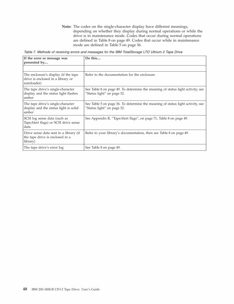
Note: The codes on the single-character display have different meanings,depending on whether they display during normal operations or while thedrive is in maintenance mode. Codes that occur during normal operationsare defined in Table 8 on page 49. Codes that occur while in maintenancemode are defined in Table 5 on page 36.
Table 7. Methods of receiving errors and messages for the IBM TotalStorage LTO Ultrium 2 Tape Drive
If the error or message waspresented by....
Do this....
The enclosure’s display (if the tapedrive is enclosed in a library orautoloader)
Refer to the documentation for the enclosure.
The tape drive’s single-characterdisplay and the status light flashesamber
See Table 8 on page 49. To determine the meaning of status light activity, see“Status light” on page 32.
The tape drive’s single-characterdisplay and the status light is solidamber
See Table 5 on page 36. To determine the meaning of status light activity, see“Status light” on page 32.
SCSI log sense data (such asTapeAlert flags) or SCSI drive sensedata
See Appendix B, “TapeAlert flags”, on page 71, Table 8 on page 49.
Drive sense data sent to a library (ifthe tape drive is enclosed in alibrary)
Refer to your library’s documentation, then see Table 8 on page 49.
The tape drive’s error log See Table 8 on page 49.
48 IBM 200/400GB LTO-2 Tape Drive: User’s Guide

Descriptions and corrective actions for errors and messagesTable 8 gives descriptions of the errors and messages that pertain to the LTO-2, andtells what to do when you receive them.
Attention: If the tape drive detects a permanent error and displays an error codeother than 0, it automatically performs a drive dump. If you force a drive dump,the existing dump will be overwritten and data will be lost. After you force a drivedump, do not turn off the power to the tape drive or you may lose the dump data.
Table 8. Codes for error conditions and informational messages for the IBM 200/400GB LTO-2 Tape Drive. Thesingle-character display clears if you power-off the drive.
Code Cause and Action
0 No error occurred and no action is required. This code displays:
v When power is cycled (turned off, then on) to the tape drive.
v When diagnostics have finished running and no error occurred.
Note: The single-character display is blank during normal operation of the tape drive.
1 Cooling problem. The tape drive detected that the recommended operating temperature wasexceeded. Perform the following action:
1. If a fan is present in the enclosure, ensure that it is rotating and is quiet. If not, replace the fan(for instructions about replacing the fan, see your enclosure’s documentation).
2. Remove any blockage that prevents air from flowing freely through the tape drive.
3. Ensure that the operating temperature and airflow is within the specified range (seeAppendix C, “Specifications”, on page 75).
4. If the operating temperature is within the specified range and the problem persists, replace thetape drive.
The error code clears when you power-off the tape drive or place it in maintenance mode.
2 Power problem. The tape drive detected that the externally supplied power is either approachingthe specified voltage limits (the drive is still operating) or is outside the specified voltage limits(the drive is not operating). Perform the following action:
1. Ensure that the power connector is properly seated.
2. Ensure that the proper dc voltages are being applied within the tolerances allowed (seeAppendix C, “Specifications”, on page 75).
3. If the proper voltages are being applied but the problem persists, replace the tape drive.
The error code clears when you power-off the tape drive or place it in maintenance mode.
3 Firmware problem. The tape drive determined that a firmware error occurred. Perform thefollowing action:
1. Collect a drive dump from one of the following:Note: Do not force a new dump; the tape drive has already created one.
v Server’s SCSI interface by using a device driver utility or system tool. To obtain a dump,determine whether your server is installed with a utility that can read files from the server’smemory. If it is, use that utility to obtain the dump. You will be instructed where to send thedump information by the IBM service or support person who asked you to obtain the dump.
v Enclosure (refer to the procedures for reading a drive dump in your enclosure’sdocumentation)
v Ultrium 2 Tape Drive (to read a drive dump, use Function Code 5 in Table 5 on page 36)
2. Power the tape drive off and on, then retry the operation that produced the error.
3. If the problem persists, download new firmware and retry the operation.
The error code clears when you power-off the tape drive or place it in maintenance mode.
4 Please contact IBM Support by following the instructions in Appendix D, “Product warranty andsupport information”, on page 77.
Chapter 5. Resolving problems 49

Table 8. Codes for error conditions and informational messages for the IBM 200/400GB LTO-2 TapeDrive (continued). The single-character display clears if you power-off the drive.
Code Cause and Action
5 Tape drive hardware problem. The drive determined that a tape path or read/write erroroccurred. To prevent damage to the drive or tape, the drive will not allow you to insert a cartridgeif the current cartridge was successfully ejected. The error code may clear when you cycle powerto the tape drive or place it in maintenance mode. If the problem persists, replace the tape drive.
50 IBM 200/400GB LTO-2 Tape Drive: User’s Guide
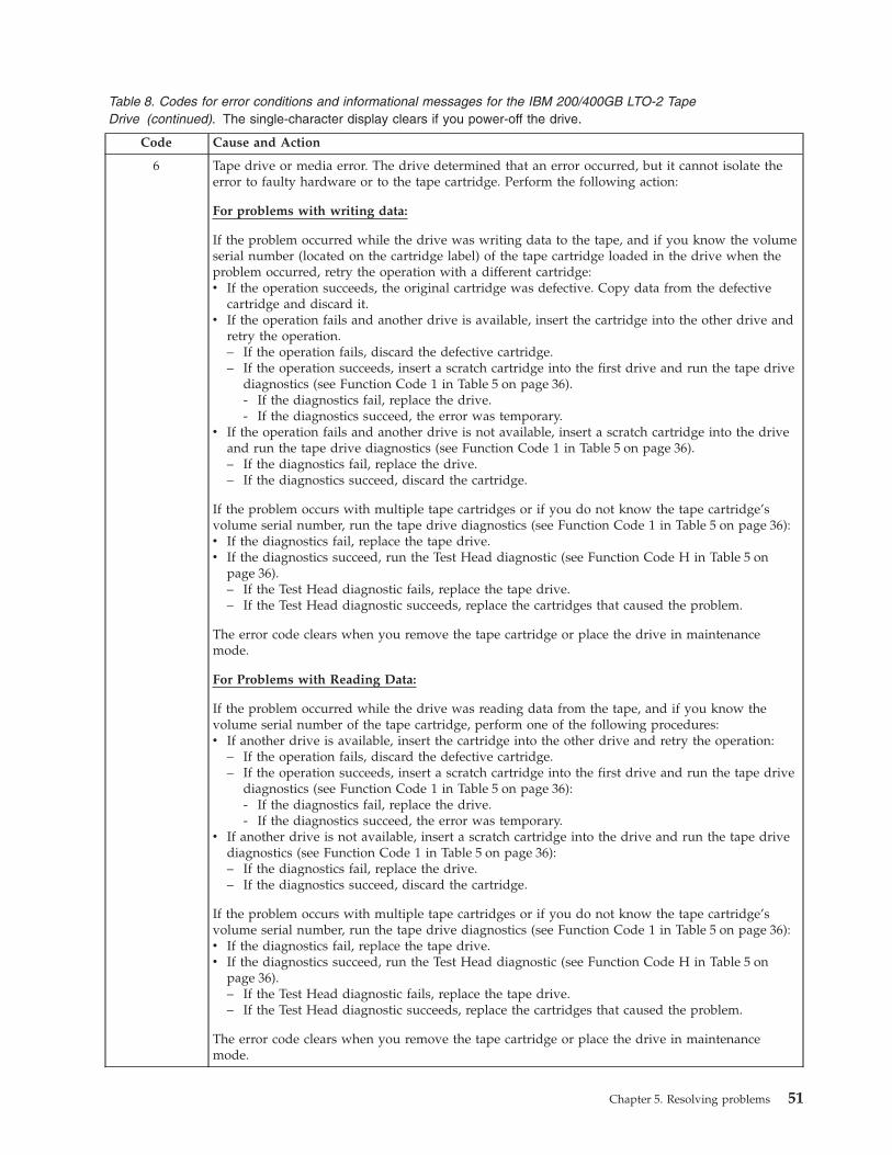
Table 8. Codes for error conditions and informational messages for the IBM 200/400GB LTO-2 TapeDrive (continued). The single-character display clears if you power-off the drive.
Code Cause and Action
6 Tape drive or media error. The drive determined that an error occurred, but it cannot isolate theerror to faulty hardware or to the tape cartridge. Perform the following action:
For problems with writing data:
If the problem occurred while the drive was writing data to the tape, and if you know the volumeserial number (located on the cartridge label) of the tape cartridge loaded in the drive when theproblem occurred, retry the operation with a different cartridge:v If the operation succeeds, the original cartridge was defective. Copy data from the defective
cartridge and discard it.v If the operation fails and another drive is available, insert the cartridge into the other drive and
retry the operation.– If the operation fails, discard the defective cartridge.– If the operation succeeds, insert a scratch cartridge into the first drive and run the tape drive
diagnostics (see Function Code 1 in Table 5 on page 36).- If the diagnostics fail, replace the drive.- If the diagnostics succeed, the error was temporary.
v If the operation fails and another drive is not available, insert a scratch cartridge into the driveand run the tape drive diagnostics (see Function Code 1 in Table 5 on page 36).– If the diagnostics fail, replace the drive.– If the diagnostics succeed, discard the cartridge.
If the problem occurs with multiple tape cartridges or if you do not know the tape cartridge’svolume serial number, run the tape drive diagnostics (see Function Code 1 in Table 5 on page 36):v If the diagnostics fail, replace the tape drive.v If the diagnostics succeed, run the Test Head diagnostic (see Function Code H in Table 5 on
page 36).– If the Test Head diagnostic fails, replace the tape drive.– If the Test Head diagnostic succeeds, replace the cartridges that caused the problem.
The error code clears when you remove the tape cartridge or place the drive in maintenancemode.
For Problems with Reading Data:
If the problem occurred while the drive was reading data from the tape, and if you know thevolume serial number of the tape cartridge, perform one of the following procedures:v If another drive is available, insert the cartridge into the other drive and retry the operation:
– If the operation fails, discard the defective cartridge.– If the operation succeeds, insert a scratch cartridge into the first drive and run the tape drive
diagnostics (see Function Code 1 in Table 5 on page 36):- If the diagnostics fail, replace the drive.- If the diagnostics succeed, the error was temporary.
v If another drive is not available, insert a scratch cartridge into the drive and run the tape drivediagnostics (see Function Code 1 in Table 5 on page 36):– If the diagnostics fail, replace the drive.– If the diagnostics succeed, discard the cartridge.
If the problem occurs with multiple tape cartridges or if you do not know the tape cartridge’svolume serial number, run the tape drive diagnostics (see Function Code 1 in Table 5 on page 36):v If the diagnostics fail, replace the tape drive.v If the diagnostics succeed, run the Test Head diagnostic (see Function Code H in Table 5 on
page 36).– If the Test Head diagnostic fails, replace the tape drive.– If the Test Head diagnostic succeeds, replace the cartridges that caused the problem.
The error code clears when you remove the tape cartridge or place the drive in maintenancemode.
Chapter 5. Resolving problems 51

Table 8. Codes for error conditions and informational messages for the IBM 200/400GB LTO-2 TapeDrive (continued). The single-character display clears if you power-off the drive.
Code Cause and Action
7 A high probability of media error. The tape drive determined that an error occurred because of afaulty tape cartridge. Try another tape cartridge. If the problem occurs with multiple tapecartridges, see “Resolving media-related problems” on page 55.
The error code clears when you remove the tape cartridge or place the drive in maintenancemode.
8 For SCSI drive:
Tape drive or SCSI bus failure. The tape drive determined that a failure occurred in the tapedrive’s hardware or in the SCSI bus. See “Fixing SCSI bus errors” on page 53. The error codeclears 10 seconds after the drive detected the error or when you place the drive in maintenancemode.
9 Tape drive or LDI (RS-422) error. The tape drive determined that a failure occurred in the tapedrive hardware or in the LDI (RS-422) connection. Run the LDI or RS-422 wrap test (see FunctionCode 7 in Table 5 on page 36):
v If the diagnostic fails, replace the tape drive.
v If the diagnostic runs successfully, the problem is with the enclosure or the cable to theenclosure. Refer to your enclosure’s documentation.
The error code clears when you place the drive in maintenance mode.
o, c, b, or h No error or message assigned. There may be a problem with the single-character display. Turn thepower off, then on and determine whether all segments on the single-character display are lit. Ifso, you may have a down-level version of both your enclosure’s firmware and documentation (thedocumentation may not describe all of the available error codes). Refer to the latest version of thefirmware or documentation.
A Tape drive hardware problem. The tape drive determined that a problem occurred whichdegraded the operation of the tape drive, but it did not restrict continued use. If the problempersists, replace the tape drive. The drive is usable, though the single-character display continuesto indicate an error and the status light flashes amber.
The error code may clear when you cycle power to the tape drive or place it in maintenancemode.
B No error or message is assigned. See error code 8 in this table.
C The tape drive needs to be cleaned. Clean the tape drive. See “Cleaning the drive head” onpage 35.
The error code clears when you clean the tape drive or place it in maintenance mode.
D No error or message assigned. See error code 0 in this table.
52 IBM 200/400GB LTO-2 Tape Drive: User’s Guide

Resolving problems reported by the serverThe procedure for fixing SCSI bus errors varies, depending on whether the error isconsistent or intermittent, and whether your configuration contains single ormultiple LTO-2s. The sections that follow describe how to fix each type of error.
Fixing SCSI bus errors
Fixing a consistent error with a single drive on a SCSI bus1. Ensure that the power is on to the LTO-2.2. Ensure that the tape drive’s SCSI address is the same as the SCSI address
assigned by the server.3. Run the SCSI wrap test (see Function Code 6 in Table 5 on page 36).
v If the test runs successfully, replace the SCSI terminator first, then the SCSIcable and the interposer (if installed). Repeat the operation that caused theerror. If you replaced the SCSI terminator or SCSI cable and the problempersists, the fault is with the server’s hardware or software. To isolate thecause of the failure, refer to the server’s service documentation.
v If the test fails, replace the tape drive (see “Removing a SCSI tape drive froman enclosure” on page 57).
Fixing a consistent error with multiple drives on a SCSI busWhen a consistent error occurs in a configuration that has multiple tape drives onthe SCSI bus, you must determine if the problem exists with more than one tapedrive. If the problem is with all of the devices on the SCSI bus, the bus is stuck ina SCSI phase and cannot change to another phase or the SCSI cable from theserver to the first device is defective.1. Ensure that the SCSI cable from the server to the first device is connected.2. Disconnect all but the first tape drive on the SCSI bus. Move the terminator to
the first SCSI device.3. Run a device driver utility (such as IBM’s ntutil or tapeutil) to determine
whether the error will occur.v If the error occurs, run the SCSI wrap test on the first tape drive (see
Function Code 6 in Table 5 on page 36).– If the test runs successfully, replace the SCSI terminator first, then the
SCSI cable and the interposer (if installed) to the first tape drive. Repeatthe operation that caused the error. If you replaced the SCSI terminator orSCSI cable and the problem persists, the fault is with the server’shardware or software. To isolate the cause of the failure, refer to theserver’s service documentation.
– If the test fails, replace the tape drive (see “Removing a SCSI tape drivefrom an enclosure” on page 57).
v If the error does not occur, connect one tape drive at a time back to the busand repeat step 3 for each tape drive until you can identify which drive isdefective.
Note: Ensure that the SCSI terminator is always on the last tape drive on theSCSI bus.
4. Determine if the problem is with only one tape drive or with two or more tapedrives.v If the problem is with only one tape drive, run the SCSI wrap test on that
tape drive (see Function Code 6 in Table 5 on page 36).
Chapter 5. Resolving problems 53
– If the test runs successfully, replace the SCSI terminator first, then theSCSI cable to that tape drive and interposer (if installed).
– If the test fails, replace the tape drive (see “Removing a SCSI tape drivefrom an enclosure” on page 57).
v If the problem is with two or more tape drives, locate the first tape drive thathas the error and replace the SCSI cable that connects the tape drive and theinterposer (if installed).
Fixing an intermittent error with a single drive on a SCSI bus1. Replace the SCSI terminator on the tape drive.2. Run the operation that caused the error. If the problem persists, the problem
may be with the cable.3. Isolate which cable is causing the problem by replacing one cable at a time and
running the operation that caused the error after each replacement. If theproblem persists after all cables have been replaced, the problem may be withthe Ultrium 2 Tape Drive.
4. Replace the tape drive (see “Removing a SCSI tape drive from an enclosure” onpage 57). If the problem persists, the problem is with your server. Consult yourserver’s documentation.
Fixing an intermittent error with multiple drives on a SCSI busRefer to the server’s error logs to determine which tape drive is the source of theproblem:v If only one tape drive is reporting a SCSI failure, replace that tape drive (see
“Removing a SCSI tape drive from an enclosure” on page 57).v If multiple tape drives are reporting SCSI failures, the problem may be with the
terminator or the SCSI cables:– Replace the terminator and run the operation that caused the error. If the
problem persists, the problem may be with the cables.– Isolate which cable is causing the problem by replacing one cable at a time
and run the operation that caused the error after each replacement.
54 IBM 200/400GB LTO-2 Tape Drive: User’s Guide
Resolving media-related problemsTo resolve problems that are related to media, the LTO-2’s firmware includes:v Test Cartridge & Media diagnostic that verifies whether a suspect cartridge and
its magnetic tape are acceptable for use.v Statistical Analysis and Reporting System (SARS) to assist in isolating failures
between media and hardware. To determine the cause of failure, SARS uses thecartridge performance history that is saved in the cartridge memory (CM) andthe drive performance history that is kept in the drive’s flash erasableprogrammable read-only memory (EPROM). Any failures that SARS detects arereported as TapeAlert flags on the server (see Appendix B, “TapeAlert flags”, onpage 71).Attention: If you insert the IBM LTO Ultrium Data Cartridge into anothermanufacturer’s tape drive, the SARS data in the cartridge memory may becomelost or invalid.
If you encounter a media-related problem, use the following procedure:
Attention: When you run the Test Cartridge & Media diagnostic, data on thesuspect tape is overwritten. Use only a scratch data cartridge to run the test.1. If possible, run the tape cartridge in a different tape drive. If the operation in
the other tape drive fails and 6 or 7 displays, replace the media. If theoperation succeeds, run the Test Cartridge & Media diagnostic (see FunctionCode E in Table 5 on page 36).
2. If the Test Cartridge & Media diagnostic fails, replace the media. If it runssuccessfully, clean the tape drive and run the tape drive diagnostics (see“Cleaning the drive head” on page 35 and Function Code 1 in Table 5 onpage 36).
3. If the tape drive diagnostics fail, replace the tape drive. If the tape drivediagnostics run successfully, perform the operation that produced the initialmedia error.
Chapter 5. Resolving problems 55

56 IBM 200/400GB LTO-2 Tape Drive: User’s Guide

Chapter 6. Servicing the tape drive
Removing a SCSI tape drive from an enclosureTo remove an IBM 200/400GB LTO-2 Tape Drive from an enclosure, perform thefollowing steps:1. Ensure that the tape drive does not contain a tape cartridge.2. Deconfigure the drive from the server (for instructions, see your server’s
documentation).3. Turn off the power to the enclosure. Disconnect the power cable from the
enclosure and the electrical outlet.4. Remove the cover of the enclosure.5. Disconnect the internal power cable from the power connector (see �4� in
Figure 18).6. If connected, disconnect the internal LDI (RS-422) cable from the LDI (RS-422)
connector �5�.7. Disconnect the internal SCSI cable from the SCSI connector �2�.8. Perform one of the following procedures on the SCSI ID connector �3�:
v If your enclosure uses an internal SCSI ID switch, disconnect it from theSCSI ID connector.
v If your enclosure uses jumpers to set the SCSI ID, do not remove them fromthe connector.
9. Remove the mounting screws from the side brackets of the chassis (see �2� inFigure 3 on page 10).
10. Remove the tape drive from the enclosure.11. To reassemble, reverse these steps.
Figure 18. Rear view of the IBM 200/400GB LTO-2 Tape Drive
© Copyright IBM Corp. 2003 57

Manually removing a tape cartridgeIf problem-determination procedures identify the LTO-2 as the source of a problem,you can optionally perform one of the following:v Replace the entire unit. For more information, contact your OEM Product
Application Engineer (PAE).v Manually remove the cartridge (see “Removing the Cartridge”).v If you are unable to manually remove the cartridge, contact trained service
personnel for assistance. Refer the service personnel to the instructions in“Fixing an internal jam” on page 61.
Attention:If you are not a trained service person, do not attempt to open the drive forrepairs. Attempting a repair other than the manual removal of a tapecartridge will void your warranty.
Removing the CartridgeIf a tape cartridge fails to eject from the LTO-2, you can manually remove thecartridge. The following tools are required for the procedure:v 2.5-mm allen wrenchv Small-blade screwdriver or potentiometer-setting toolv 2-mm hex wrenchv #3 Phillips screwdriverv Needle-nose pliersv Flashlight (optional)
Attention: Before performing this procedure, note the following:
v Ensure that you have attempted all normal methods of removing the tapecartridge from the drive. Refer to “Removing a tape cartridge” on page 35 andthe troubleshooting tips in Table 6 on page 47.
v This procedure may damage the stuck tape cartridge. If you use this procedure,copy the data from the stuck cartridge to another cartridge. If you choose toreuse the stuck cartridge, refer to the instructions in “Repositioning orreattaching a leader pin” on page 20. If you believe the cartridge has beendamaged, replace it.
v Do not use a power screwdriver to perform this procedure because it candestroy the tape.
v Never touch the head or electronic components within the drive. Touching maycause contamination or damage by electrostatic discharge.
58 IBM 200/400GB LTO-2 Tape Drive: User’s Guide

To manually remove a tape cartridge, perform the following steps:1. Place the drive so that the front faces you, then tilt it on its left side (see
Figure 19).2. Locate the access hole at the bottom of the unit (see �1� in Figure 19).3. Insert a 2.5-mm allen wrench into the access hole and position the wrench so
that it is seated in the screw of the supply reel motor.4. Push open the door of the tape load compartment and locate the flag �2� on
the drive’s takeup reel.
Attention: In the following step, rotate the allen wrench clockwise, notcounterclockwise. A counterclockwise motion may damage the tape.5. To determine whether the tape is broken, watch the flag �2� on the drive’s
takeup reel while you rotate the allen wrench �1� clockwise (do not let thewrench move counterclockwise):v If you feel resistance to the allen wrench while attempting to turn the
supply reel motor screw clockwise, go to step 7 on page 60.v If the takeup reel turns when you rotate the supply reel motor screw
clockwise with the allen wrench, the tape is not broken. Go to step 6 onpage 60.
v If the takeup reel does not turn when you rotate the supply reel motorscrew clockwise with the allen wrench and if supply reel motor screwrotates freely, the tape is broken. You must determine the location of theleader block. To do so, insert a small-blade screwdriver orpotentiometer-setting tool into the access hole for the loader motor gear �3�.Rotate the screwdriver counterclockwise. You may have to rotate for alengthy period:– If the cartridge moves up, the tape is completely in the cartridge and the
leader block is in the home position. Continue rotating the screwdriveruntil the cartridge ejects. Remove the cartridge.
– If you feel resistance and the cartridge does not move up, the leaderblock is not in the home position. Go to “Fixing an internal jam” onpage 61.
Figure 19. Determining whether the tape is broken
Chapter 6. Servicing the tape drive 59
6. Continue to rotate the allen wrench until you feel resistance. The tape hasbeen rewound as far as it can go without unthreading.
Note: The number of required rotations depends on where the beginning ofthe tape is on the cartridge’s takeup reel. You may have to rotate theallen wrench for a lengthy period.
7. With the allen wrench still inserted into the bottom access hole, insert asmall-blade screwdriver or potentiometer-setting tool into the access hole forthe loader motor gear �3�.
8. While keeping torque on the supply reel motor screw and rotating the allenwrench �1� clockwise, rotate the loader motor gear with the small-bladescrewdriver �3� counterclockwise (see arrow). As you rotate the screwdriver,the allen wrench moves slightly.
9. With the small-blade screwdriver, continue to rotate the loader motor gear inthe unload direction (counterclockwise):v If you feel no resistance to the allen wrench and the cartridge slowly moves
up and out of the tape load compartment to the fully ejected position, theprocedure was successful. Remove the small-blade screwdriver and go tostep 10.
v If you feel resistance to the allen wrench and the cartridge does not move,the loader mechanism is jammed or the leader block is not at the homeposition. Remove the small-blade screwdriver and go to “Fixing an internaljam” on page 61.
10. Remove the tape cartridge.11. To ensure that the drive operates properly, refer to page 36 and select Function
Code 1 - Run Tape Drive Diagnostics.
After you remove the stuck tape cartridge, copy the data on the tape to anothertape. Then, if appropriate, return the stuck tape cartridge in its original packagingor in the packaging from its replacement to your reseller. If the leader pin detachedfrom the tape in the cartridge, go to “Repositioning or reattaching a leader pin” onpage 20.
60 IBM 200/400GB LTO-2 Tape Drive: User’s Guide
Fixing an internal jam
Attention:This procedure must be performed only by trained service personnel.
If problem-determination procedures identify the LTO-2 Tape Drive as thesource of a problem, replace the entire unit. If you are not a trained serviceperson, do not attempt to open the drive for repairs. Attempting a repairother than the manual removal of a tape cartridge will void your warranty.
Before performing this procedure, ensure that you have completed the stepsthat begin on page 59. Do not attempt this procedure until you havecompleted these steps.
If you have reached this point, the tape is broken or the leader pin dropped (orlooked like it dropped) from the leader block. To fix these conditions, perform thefollowing procedure.1. If the drive is mounted in an enclosure, perform the procedure to remove it
(see “Removing a SCSI tape drive from an enclosure” on page 57).2. Place the drive on a nonslip surface.3. Remove the cover of the drive by performing the following steps:
a. Use an appropriate tool to remove the three screws and washers (see �1�in Figure 20 on page 62) that secure the bezel �2�. Remove the bezel.
b. Use a screwdriver to remove the four cover-mounting screws and washers�3�.
c. Remove the cover by lifting it up. Set the cover aside.
Chapter 6. Servicing the tape drive 61
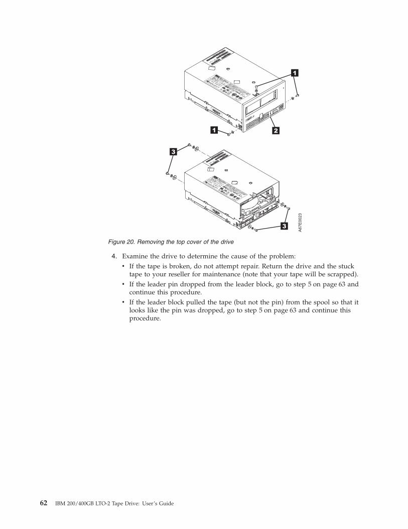
4. Examine the drive to determine the cause of the problem:v If the tape is broken, do not attempt repair. Return the drive and the stuck
tape to your reseller for maintenance (note that your tape will be scrapped).v If the leader pin dropped from the leader block, go to step 5 on page 63 and
continue this procedure.v If the leader block pulled the tape (but not the pin) from the spool so that it
looks like the pin was dropped, go to step 5 on page 63 and continue thisprocedure.
Figure 20. Removing the top cover of the drive
62 IBM 200/400GB LTO-2 Tape Drive: User’s Guide

5. Place the tape drive so that the front faces you, then tilt it on its left side (seeFigure 21).
6. At the bottom of the drive, locate the access hole (�1� in Figure 21).
Attention: In the following steps, do not allow drive components to touch thehead �2�. Damage may result to the head.
7. Insert a 2.5-mm allen wrench into the access hole and position the wrench sothat it is seated in the screw of the supply reel motor.
8. With clean needle-nose pliers, grasp the end of the leader pin and pull it outof the cartridge so that you can grip it with your fingers (see �3� in Figure 21).
Note: If the leader pin is not connected to the tape, set the pin aside. Afteryou remove the cartridge, reattach the pin (see “Repositioning orreattaching a leader pin” on page 20).
Figure 21. Rewinding the leader pin into the tape cartridge
Chapter 6. Servicing the tape drive 63
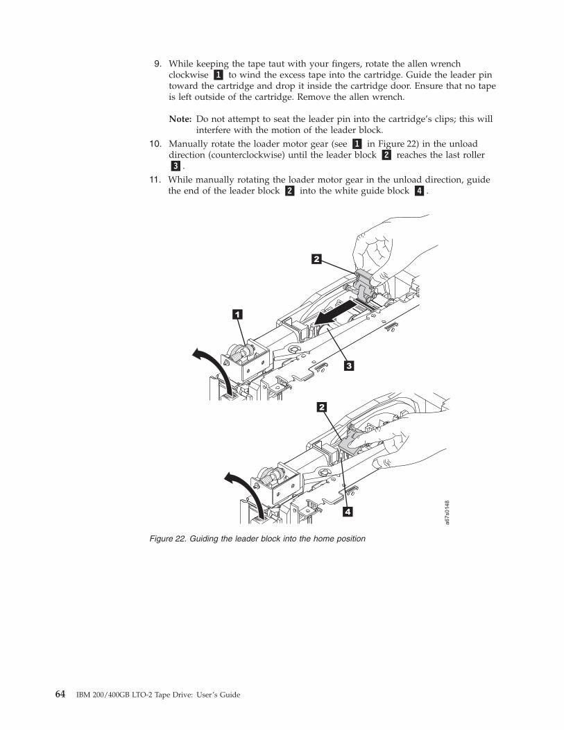
9. While keeping the tape taut with your fingers, rotate the allen wrenchclockwise �1� to wind the excess tape into the cartridge. Guide the leader pintoward the cartridge and drop it inside the cartridge door. Ensure that no tapeis left outside of the cartridge. Remove the allen wrench.
Note: Do not attempt to seat the leader pin into the cartridge’s clips; this willinterfere with the motion of the leader block.
10. Manually rotate the loader motor gear (see �1� in Figure 22) in the unloaddirection (counterclockwise) until the leader block �2� reaches the last roller�3�.
11. While manually rotating the loader motor gear in the unload direction, guidethe end of the leader block �2� into the white guide block �4�.
Figure 22. Guiding the leader block into the home position
64 IBM 200/400GB LTO-2 Tape Drive: User’s Guide

12. Rotate the loader motor gear in the unload direction until the leader block isfully inside the drive.
Chapter 6. Servicing the tape drive 65

13. Continue to rotate the loader motor gear counterclockwise. The leader blockretracts and occupies the opening to the drive (see �1� in Figure 23).
Figure 23. Rotating the loader motor gear so that the leader block retracts. The drive isshown on its side. The head is on the right and the arm of the head brush at the bottom ofthe figure.
66 IBM 200/400GB LTO-2 Tape Drive: User’s Guide

14. Rotate the loader motor gear counterclockwise until you feel resistance andthe cartridge rises and ejects (see Figure 24).
15. Remove the tape cartridge. If the leader pin is not seated correctly in thecartridge, see “Repositioning or reattaching a leader pin” on page 20.
16. Copy the data on the stuck tape cartridge to another cartridge. If appropriate,return the stuck tape cartridge for analysis in its original packaging or in thepackaging from its replacement.
17. Reassemble the tape drive by reversing the preceding steps.18. To ensure that the drive operates properly, refer to page 36 and select
Function Code 1 - Run Tape Drive Diagnostics.
Figure 24. Rotating the loader motor gear until the cartridge ejects
Chapter 6. Servicing the tape drive 67

68 IBM 200/400GB LTO-2 Tape Drive: User’s Guide

Appendix A. Tools and supplies
Table 9 lists the tools and supplies that you can use with the IBM TotalStorage LTOUltrium 2 Tape Drive. To order tools and supplies, visit the web atwww.ibm.com/storage/lto.
Table 9. Tools and supplies for the IBM 200/400GB LTO-2 Tape Drive
IBM Part Number Product Description
08L9129 Leader pin reattachment kit
- - 2.5-mm allen wrench (procure locally)
- - Plastic or blunt-end tweezers (procure locally)
08L9870 IBM LTO-2 Ultrium 200 GB Data Cartridge
08L9124 IBM LTO Ultrium Cleaning Cartridge
35L2086 IBM Cleaning Cartridge (Ultrium LTO 2)
19P5897 IBM LTO Ultrium Data Cartridge bar code labels
08L9267 IBM LTO Ultrium Cleaning Cartridge bar code labels
© Copyright IBM Corp. 2003 69

70 IBM 200/400GB LTO-2 Tape Drive: User’s Guide

Appendix B. TapeAlert flags
TapeAlert is a patented technology and standard of the American NationalStandards Institute (ANSI) that defines conditions and problems that areexperienced by tape drives. The technology enables a server to read TapeAlertflags from a tape drive through the SCSI or Library/Drive Interface (LDI or RS-422interface). The server reads the flags from Log Sense Page 0x2E. This appendix liststhe TapeAlert flags that are supported by the IBM 200/400GB LTO-2 Tape Drive.
TapeAlert Flags supported by the drive
TapeAlert Flags Supported by the IBM 200/400GB LTO-2 Tape Drive
FlagNumber
FlagParameter
(in hex)Flag Description Action Required
3 03h Hard error Set for any unrecoverable read,write, or positioning error. (Thisflag is set in conjunction withflags 4, 5, or 6.)
See the Action Required columnfor Flag 4, 5, or 6 in this table.
4 04h Media Set for any unrecoverable read,write, or positioning error that isdue to a faulty tape cartridge.
Replace the tape cartridge.
5 05h Read failure Set for any unrecoverable readerror where isolation is uncertainand failure could be due to afaulty tape cartridge or to faultydrive hardware.
If Flag 4 is also set, the cartridgeis defective. Replace the tapecartridge. If Flag 4 is not set, seeerror code 6 in Table 8 onpage 49.
6 06h Write failure Set for any unrecoverable writeor positioning error whereisolation is uncertain and failurecould be due to a faulty tapecartridge or to faulty drivehardware.
If Flag 9 is also set, make surethat the write-protect switch isset so that data can be written tothe tape (see “Setting thewrite-protect switch” onpage 16). If Flag 4 is also set, thecartridge is defective. Replacethe tape cartridge. If Flag 4 isnot set, see error code 6 inTable 8 on page 49.
8 08h Not data grade Set when severe servo errorsoccur while loading a tapecartridge.
Replace the tape cartridge. If thiserror occurs with multiple tapes,see error code 6 in Table 8 onpage 49.
9 09h Write protect Set when the tape drive detectsthat the tape cartridge iswrite-protected.
Make sure that the cartridge’swrite-protect switch is set so thatthe tape drive can write data tothe tape (see “Setting thewrite-protect switch” onpage 16).
10 0Ah No removal Set when the tape drive receivesan UNLOAD command after theserver prevented the tapecartridge from being removed.
Refer to the documentation foryour server’s operating system.
© Copyright IBM Corp. 2003 71

TapeAlert Flags Supported by the IBM 200/400GB LTO-2 Tape Drive
FlagNumber
FlagParameter
(in hex)Flag Description Action Required
11 0Bh Cleaning media Set when you load a cleaningcartridge into the drive.
No action required.
12 0Ch Unsupported format Set when you load anunsupported cartridge type intothe drive or when the cartridgeformat has been corrupted.
Use a supported tape cartridge.
15 0Fh Cartridge memorychip failure
Set when a cartridge memory(CM) failure is detected on theloaded tape cartridge.
Replace the cartridge. If thiserror occurs on multiple tapes,see error code 6 in Table 8 onpage 49.
16 10h Forced eject Set when you manually unloadthe tape cartridge while thedrive was reading or writing.
No action required.
18 12h Tape directorycorrupted in thecartridge memory
Set when the drive detects thatthe tape directory in thecartridge memory has beencorrupted.
Re-read all data from the tape torebuild the tape directory.
20 14h Clean now Set when the tape drive detectsthat it needs cleaning.
Clean the tape drive. See“Cleaning the drive head” onpage 35.
21 15h Clean periodic Set when the drive detects that itneeds routine cleaning.
Clean the tape drive as soon aspossible. The drive can continueto operate, but you should cleanthe drive soon. See “Cleaningthe drive head” on page 35.
22 16h Expired clean Set when the tape drive detects acleaning cartridge that hasexpired.
Replace the cleaning cartridge.
23 17h Invalid cleaning tape Set when the drive expects acleaning cartridge and theloaded cartridge is not acleaning cartridge.
Use a valid cleaning cartridge.
30 1Eh Hardware A Set when a hardware failureoccurs which requires that youreset the tape drive to recover.
If resetting the drive does notrecover the error, use the errorcode from the single-characterdisplay, library user interface, orSCSI drive sense data. SeeTable 8 on page 49.
31 1Fh Hardware B Set when the tape drive fails itsinternal self tests.
Use the error code on thesingle-character display, libraryuser interface, or SCSI drivesense data. See Table 8 onpage 49.
32 20h Interface Set when the tape drive detects aproblem with the SCSI or LDI(RS-422) interface.
Locate error code 8 or 9 inTable 8 on page 49.
33 21h Eject media Set when a failure occurs thatrequires you to unload thecartridge from the drive.
Unload and reload the tapecartridge.
72 IBM 200/400GB LTO-2 Tape Drive: User’s Guide
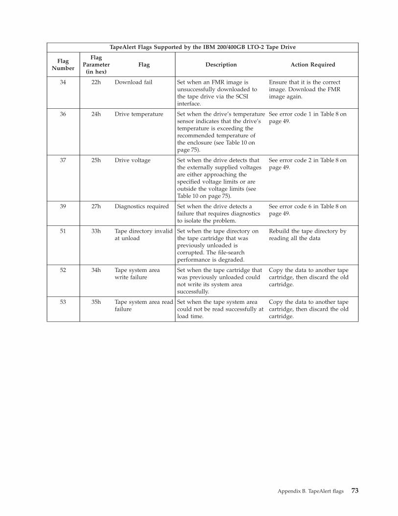
TapeAlert Flags Supported by the IBM 200/400GB LTO-2 Tape Drive
FlagNumber
FlagParameter
(in hex)Flag Description Action Required
34 22h Download fail Set when an FMR image isunsuccessfully downloaded tothe tape drive via the SCSIinterface.
Ensure that it is the correctimage. Download the FMRimage again.
36 24h Drive temperature Set when the drive’s temperaturesensor indicates that the drive’stemperature is exceeding therecommended temperature ofthe enclosure (see Table 10 onpage 75).
See error code 1 in Table 8 onpage 49.
37 25h Drive voltage Set when the drive detects thatthe externally supplied voltagesare either approaching thespecified voltage limits or areoutside the voltage limits (seeTable 10 on page 75).
See error code 2 in Table 8 onpage 49.
39 27h Diagnostics required Set when the drive detects afailure that requires diagnosticsto isolate the problem.
See error code 6 in Table 8 onpage 49.
51 33h Tape directory invalidat unload
Set when the tape directory onthe tape cartridge that waspreviously unloaded iscorrupted. The file-searchperformance is degraded.
Rebuild the tape directory byreading all the data
52 34h Tape system areawrite failure
Set when the tape cartridge thatwas previously unloaded couldnot write its system areasuccessfully.
Copy the data to another tapecartridge, then discard the oldcartridge.
53 35h Tape system area readfailure
Set when the tape system areacould not be read successfully atload time.
Copy the data to another tapecartridge, then discard the oldcartridge.
Appendix B. TapeAlert flags 73

74 IBM 200/400GB LTO-2 Tape Drive: User’s Guide

Appendix C. Specifications
Table 10 gives the physical, power, and environmental specifications for the IBM200/400GB LTO-2 Tape Drive. Specifications for tape cartridges are given in“Environmental and shipping specifications for tape cartridges” on page 27.
Table 10. Specifications for the IBM 200/400GB LTO-2 Tape Drive
Specification Measurement
Physical Specifications
Width 146.0 mm (5.75 in.) without bezel
148.3 mm (5.84 in.) with bezel
Length 205.5 mm (8.09 in.) without bezel
210.5 mm (8.29 in.) with bezel
Height 82.5 mm (3.25 in.) without bezel
84.8 mm (3.34 in.) with bezel
Weight (without acartridge)
3 kg (6 lb 10 oz)
Power Specifications
Tolerance (see Note 1) + 5 Vdc and + 12 Vdc (±10%)
Power supply current for 5Vdc (see Note 2)
1.3 A minimum
3.1 A maximum
Power supply current for12 Vdc (see Note 2)
0.2 A minimum
1.1 A maximum
Power supply peak for 5Vdc (the instantaneouspower by the powersupply)
3.3 A for 100 ms 15.5 W
Power supply peak for 12Vdc (the instantaneouspower by the powersupply)
4.1 A for 2 ms 49.2 W
Power usage for typicalidle mode with no cartridge
10.9 W 13.9 W
Power usage for typicalidle mode with a cartridgeloaded
12.7 W 15.7 W
Power usage for readingand writing at 6.22 m/s
29 W 32 W
Power usage for sleepmode with no cartridge
9.0 W 12.0 W
Power usage for sleepmode with a cartridgeloaded
10.8 W 13.8 W
Other Specifications (for both interface types)
© Copyright IBM Corp. 2003 75

Table 10. Specifications for the IBM 200/400GB LTO-2 Tape Drive (continued)
Maximum altitude 3048 m (10,000 ft) for operating and storage
12192 m (40,000 ft) for shipping
Extraction force 250 to 750 gms-force
Environmental Specifications (for both interface types)
Environmental Factor Operating (see Note 3) Storage Shipping
Drive temperature 10 to 40°C (50 to 104°F) 1 to 60°C (33.8 to 140°F) −40 to 60°C (−40 to 140°F)
Relative humidity(noncondensing)
20 to 80% 10 to 90% 10 to 90%
Wet bulb temperature 26°C (78.8°F) 26°C (78.8°F) 26°C (78.8°F)
Notes:
1. Measured at the drive’s power connector.
2. The + 5 Vdc and + 12 Vdc maximum currents do not occur simultaneously. The Ultrium 2 Tape Drive monitorsvoltage and reports problems to the server.
3. Measured in front of the bezel, near the air intake area.
76 IBM 200/400GB LTO-2 Tape Drive: User’s Guide

Appendix D. Product warranty and support information
Warranty periodThe warranty period varies by machine type and country or region. Contact yourplace of purchase for warranty service information. Some IBM machines areeligible for on-site warranty service, depending on the country or region whereservice is performed.
Prior to on-site warranty service, you are required to go through problemdetermination with an IBM service specialist call center technician.
A warranty period of 3 years on parts and 0 years on labor means that IBM willprovide warranty service without charge for:v parts only; on an exchange basis, in the first, second, and third years of the
warranty period. IBM will charge you for any labor it provides in performanceof the repair or replacement.
v The IBM Machine Warranties Web site atwww.ibm.com/servers/support/machine_warranties/ contains a worldwideoverview of the IBM Statement of Limited Warranty for IBM Machines, aglossary of terms used in the Statement of Limited Warranty, Frequently AskedQuestions (FAQ), and links to Product Support Web pages. The IBM Statementof Limited Warranty is available from this Web site in 29 languages in PortableDocument Format (PDF).
Machine - IBM 200/400GB LTO-2 Tape Drive
Warranty period Service delivery method
Parts - 3 years, labor - 0 years Customer carry-in or mail-in
Problem determinationPrior to on-site warranty service, you are required to go through problemdetermination with an IBM service specialist call center technician. The servicespecialist will run diagnostic tests on the hardware and check the software.
Running diagnosticsThe IBM service specialist will help you determine whether your equipment isfunctioning as specified. It might be necessary to isolate the failing system, IBMcomponent, or both from any active production environment to run diagnosticsand perform defect-isolation programs. You are responsible for making the system,IBM component, or both available for running diagnostics and defect-isolationprograms.
Checking softwareThe IBM service specialist will help you ensure that the correct BIOS code,firmware, device drivers, and other supporting IBM software are installed andcorrectly configured. It might be necessary to manually gather information aboutthe relevant software levels or run IBM-approved utility programs to gather thisinformation. It might be necessary to isolate the failing from any active productionenvironment to gather this information. Youare responsible, with assistance fromthe support specialist, for gathering this information. The IBM Statement ofLimited Warranty does not include on-site assistance with this activity.
© Copyright IBM Corp. 2003 77
Warranty service and supportWith the original purchase of an IBM xSeries system, you have access to extensiveservice and support. During the IBM Machine warranty period, you may call IBMor your reseller for problem-determination assistance under the terms of the IBMStatement of Limited Warranty.
The following services are available during the warranty period:v Problem determination - Trained personnel are available to assist you with
determining if you have a hardware problem and deciding what action isnecessary to fix the problem.
v IBM hardware repair - If the problem is determined to be cause by IBMhardware under warranty, trained service personnel are available to provide theapplicable level of service, either on-site or at an IBM service center asdetermined by IBM.
v Engineering Change management - Occassionally, there might be changes thatare required after a product has been shipped from IBM. In those instances, IBMwill make Engineering Changes (ECs) available that apply to your hardware.
v Customer replaceable units (CRUs) - Some parts of IBM xSeries systems aredesignated as customer replaceable units. IBM ships CRUs to you forreplacement by you. CRUs include keyboards, monitors, memory, diskettedrives, hard disk drives, and mice (this list is not inclusive of all CRUs).
The following items are not covered under warranty service:v Replacement or use of non-IBM parts. All IBM parts contain a 7-character
identification in the format IBM FRU XXXXXXX.v Identification of software problem sources.v Installation of customer replaceable units (CRUs).v Installation and configuration of BIOS code, firmware, or device drivers that are
designated as customer installable.
See the IBM Statement of Limited Warranty for a full explanation of IBM warrantyterms. Be sure to retain your proof of purchase to obtain warranty service.
Please have the following information ready when you call:v The machine type and model of your IBM hardware product (if available)v Serial numbers of your IBM hardware productsv A description of the problemv The exact wording of any error messagesv Hardware and software configuration information
International warranty serviceIf your travel with your xSeries system or relocate it to a country or region whereyour system is sold and serviced by IBM or IBM resellers authorized to performwarranty service, International Warranty Service (IWS) is available during thewarranty period. Eligible IBM systems are identified by their four-digit machinetypes.
You can obtain IWS through the service delivery method (such as depot, carry-in,or on-site) provided in the servicing country or region. Service methods andprocedures vary by country or region, and some services or parts might not beavailable in all countries or regions. Service centers in certain countries or regions
78 IBM 200/400GB LTO-2 Tape Drive: User’s Guide

might not be able to service all models of a particular machine type. In addition,some countries or regions might have fees and restrictions that apply at the time ofservice.
To determine whether you system is eligible for IWS, go towww.ibm.com/pc/support/ and click Warranty lookup.
Purchasing additional servicesDuring and after the warranty period, you can purchase additional services, suchas support for IBM and non-IBM hardware, operating systems, and applicationprograms; network setup and configuration; upgraded or extended hardwarerepair services; and custom installations. Service availability and service namemight vary by country or region.
For more information about these service, contact your IBM marketingrepresentative.
Appendix D. Product warranty and support information 79

IBM Statement of Limited Warranty Z125-4753-06 8/2000This warranty statement consists of two parts: Part 1 and Part 2. Be sure to readPart 1 and the country-unique terms in Part 2 that apply to your country or region.
Part 1 - General TermsThis Statement of Limited Warranty includes Part 1 - General Terms and Part 2 -Country-unique Terms. The terms of Part 2 replace or modify those of Part 1. Thewarranties provided by IBM in this Statement of Limited Warranty apply only toMachines you purchase for your use, and not for resale, from IBM or your reseller.The term “Machine” means an IBM machine, its features, conversions, upgrades,elements, or accessories, or any combination of them. The term “Machine” doesnot include any software programs, whether pre-loaded with the Machine,installed subsequently or otherwise. Unless IBM specifies otherwise, the followingwarranties apply only in the country where you acquire the Machine. Nothing inthis Statement of Limited Warranty affects any statutory rights of consumers thatcannot be waived or limited by contract. If you have any questions, contact IBM oryour reseller.
The IBM Warranty for Machines
IBM warrants that each Machine 1) is free from defects in materials andworkmanship and 2) conforms to IBM’s Official Published Specifications(“Specifications”). The warranty period for a Machine is a specified, fixed periodcommencing on its Date of Installation. The date on your sales receipt is the Dateof Installation unless IBM or your reseller informs you otherwise. If a Machinedoes not function as warranted during the warranty period, and IBM or yourreseller are unable to either 1) make it do so or 2) replace it with one that is atleast functionally equivalent, you may return it to your place of purchase and yourmoney will be refunded.
Extent of Warranty
The warranty does not cover the repair or exchange of a Machine resulting frommisuse, accident, modification, unsuitable physical or operating environment,improper maintenance by you, or failure caused by a product for which IBM is notresponsible. The warranty is voided by removal or alteration of Machine or partsidentification labels.
THESE WARRANTIES ARE YOUR EXCLUSIVE WARRANTIES AND REPLACEALL OTHER WARRANTIES OR CONDITIONS, EXPRESS OR IMPLIED,INCLUDING, BUT NOT LIMITED TO, THE IMPLIED WARRANTIES ORCONDITIONS OF MERCHANTABILITY AND FITNESS FOR A PARTICULARPURPOSE. THESE WARRANTIES GIVE YOU SPECIFIC LEGAL RIGHTS ANDYOU MAY ALSO HAVE OTHER RIGHTS WHICH VARY FROM JURISDICTIONTO JURISDICTION. SOME JURISDICTIONS DO NOT ALLOW THE EXCLUSIONOR LIMITATION OF EXPRESS OR IMPLIED WARRANTIES, SO THE ABOVEEXCLUSION OR LIMITATION MAY NOT APPLY TO YOU. IN THAT EVENT,SUCH WARRANTIES ARE LIMITED IN DURATION TO THE WARRANTYPERIOD. NO WARRANTIES APPLY AFTER THAT PERIOD.
Items Not Covered by Warranty
IBM does not warrant uninterrupted or error-free operation of a Machine.
80 IBM 200/400GB LTO-2 Tape Drive: User’s Guide
Any technical or other support provided for a Machine under warranty, such asassistance via telephone with “how-to” questions and those regarding Machineset-up and installation, will be provided WITHOUT WARRANTIES OF ANYKIND.
Warranty Service
To obtain warranty service for a Machine, contact IBM or your reseller. If you donot register your Machine with IBM, you may be required to present proof ofpurchase.
During the warranty period, IBM or your reseller, if approved by IBM to providewarranty service, provides without charge certain types of repair and exchangeservice to keep Machines in, or restore them to, conformance with theirSpecifications. IBM or your reseller will inform you of the available types ofservice for a Machine based on its country of installation. At its discretion, IBM oryour reseller will 1) either repair or exchange the failing Machine and 2) providethe service either at your location or a service center. IBM or your reseller will alsomanage and install selected engineering changes that apply to the Machine.
Some parts of IBM Machines are designated as Customer Replaceable Units (called“CRUs”), e.g., keyboards, memory, or hard disk drives. IBM ships CRUs to you forreplacement by you. You must return all defective CRUs to IBM within 30 days ofyour receipt of the replacement CRU. You are responsible for downloadingdesignated Machine Code and Licensed Internal Code updates from an IBMInternet Web site or from other electronic media, and following the instructionsthat IBM provides.
When warranty service involves the exchange of a Machine or part, the item IBMor your reseller replaces becomes its property and the replacement becomes yours.You represent that all removed items are genuine and unaltered. The replacementmay not be new, but will be in good working order and at least functionallyequivalent to the item replaced. The replacement assumes the warranty servicestatus of the replaced item. Many features, conversions, or upgrades involve theremoval of parts and their return to IBM. A part that replaces a removed part willassume the warranty service status of the removed part.
Before IBM or your reseller exchanges a Machine or part, you agree to remove allfeatures, parts, options, alterations, and attachments not under warranty service.
You also agree to1. ensure that the Machine is free of any legal obligations or restrictions that
prevent its exchange;2. obtain authorization from the owner to have IBM or your reseller service a
Machine that you do not own; and3. where applicable, before service is provided:
a. follow the problem determination, problem analysis, and service requestprocedures that IBM or your reseller provides;
b. secure all programs, data, and funds contained in a Machine;c. provide IBM or your reseller with sufficient, free, and safe access to your
facilities to permit them to fulfill their obligations; andd. inform IBM or your reseller of changes in a Machine’s location.
Appendix D. Product warranty and support information 81
IBM is responsible for loss of, or damage to, your Machine while it is 1) in IBM’spossession or 2) in transit in those cases where IBM is responsible for thetransportation charges.
Neither IBM nor your reseller is responsible for any of your confidential,proprietary or personal information contained in a Machine which you return toIBM or your reseller for any reason. You should remove all such information fromthe Machine prior to its return.
Limitation of Liability
Circumstances may arise where, because of a default on IBM’s part or otherliability, you are entitled to recover damages from IBM. In each such instance,regardless of the basis on which you are entitled to claim damages from IBM(including fundamental breach, negligence, misrepresentation, or other contract ortort claim), except for any liability that cannot be waived or limited by applicablelaws, IBM is liable for no more than1. damages for bodily injury (including death) and damage to real property and
tangible personal property; and2. the amount of any other actual direct damages, up to the charges (if recurring,
12 months’ charges apply) for the Machine that is subject of the claim. Forpurposes of this item, the term “Machine” includes Machine Code andLicensed Internal Code.
This limit also applies to IBM’s suppliers and your reseller. It is the maximum forwhich IBM, its suppliers, and your reseller are collectively responsible.
UNDER NO CIRCUMSTANCES IS IBM LIABLE FOR ANY OF THE FOLLOWING:1) THIRD-PARTY CLAIMS AGAINST YOU FOR DAMAGES (OTHER THANTHOSE UNDER THE FIRST ITEM LISTED ABOVE); 2) LOSS OF, OR DAMAGETO, YOUR RECORDS OR DATA; OR 3) SPECIAL, INCIDENTAL, OR INDIRECTDAMAGES OR FOR ANY ECONOMIC CONSEQUENTIAL DAMAGES, LOSTPROFITS OR LOST SAVINGS, EVEN IF IBM, ITS SUPPLIERS OR YOURRESELLER IS INFORMED OF THEIR POSSIBILITY. SOME JURISDICTIONS DONOT ALLOW THE EXCLUSION OR LIMITATION OF INCIDENTAL ORCONSEQUENTIAL DAMAGES, SO THE ABOVE LIMITATION OR EXCLUSIONMAY NOT APPLY TO YOU.
Governing Law
Both you and IBM consent to the application of the laws of the country in whichyou acquired the Machine to govern, interpret, and enforce all of your and IBM’srights, duties, and obligations arising from, or relating in any manner to, thesubject matter of this Agreement, without regard to conflict of law principles.
Part 2 - Country-unique TermsAMERICAS
BRAZIL
Governing Law: The following is added after the first sentence:Any litigationarising from this Agreement will be settled exclusively by the court of Rio deJaneiro.
NORTH AMERICA
82 IBM 200/400GB LTO-2 Tape Drive: User’s Guide

Warranty Service: The following is added to this Section:To obtain warranty servicefrom IBM in Canada or the United States, call 1-800-IBM-SERV (426-7378).
CANADA
Governing Law: The following replaces “laws of the country in which you acquired theMachine” in the first sentence: laws in the Province of Ontario.
UNITED STATES
Governing Law: The following replaces “laws of the country in which you acquired theMachine” in the first sentence: laws of the State of New York.
ASIA PACIFIC
AUSTRALIA
The IBM Warranty for Machines: The following paragraph is added to this Section: Thewarranties specified in this Section are in addition to any rights you may haveunder the Trade Practices Act 1974 or other similar legislation and are only limitedto the extent permitted by the applicable legislation.
Limitation of Liability: The following is added to this Section: Where IBM is in breachof a condition or warranty implied by the Trade Practices Act 1974 or other similarlegislation, IBM’s liability is limited to the repair or replacement of the goods orthe supply of equivalent goods. Where that condition or warranty relates to rightto sell, quiet possession or clear title, or the goods are of a kind ordinarily acquiredfor personal, domestic or household use or consumption, then none of thelimitations in this paragraph apply.
Governing Law: The following replaces “laws of the country in which you acquired theMachine” in the first sentence: laws of the State or Territory.
CAMBODIA, LAOS, AND VIETNAM
Governing Law: The following replaces “laws of the country in which you acquired theMachine” in the first sentence:laws of the State of New York.
The following is added to this Section: Disputes and differences arising out of or inconnection with this Agreement shall be finally settled by arbitration which shallbe held in Singapore in accordance with the rules of the International Chamber ofCommerce (ICC). The arbitrator or arbitrators designated in conformity with thoserules shall have the power to rule on their own competence and on the validity ofthe Agreement to submit to arbitration. The arbitration award shall be final andbinding for the parties without appeal and the arbitral award shall be in writingand set forth the findings of fact and the conclusions of law.
All proceedings shall be conducted, including all documents presented in suchproceedings, in the English language. The number of arbitrators shall be three,with each side to the dispute being entitled to appoint one arbitrator.
The two arbitrators appointed by the parties shall appoint a third arbitrator beforeproceeding upon the reference. The third arbitrator shall act as chairman of theproceedings. Vacancies in the post of chairman shall be filled by the president ofthe ICC. Other vacancies shall be filled by the respective nominating party.Proceedings shall continue from the stage they were at when the vacancy occurred.
Appendix D. Product warranty and support information 83
If one of the parties refuses or otherwise fails to appoint an arbitrator within 30days of the date the other party appoints its, the first appointed arbitrator shall bethe sole arbitrator, provided that the arbitrator was validly and properlyappointed.
The English language version of this Agreement prevails over any other languageversion.
HONG KONG AND MACAU
Governing Law: The following replaces “laws of the country in which you acquired theMachine” in the first sentence: laws of Hong Kong Special Administrative Region.
INDIA
Limitation of Liability: The following replaces items 1 and 2 of this Section:
1. liability for bodily injury (including death) or damage to real property andtangible personal property will be limited to that caused by IBM’s negligence;
2. as to any other actual damage arising in any situation involvingnonperformance by IBM pursuant to, or in any way related to the subject ofthis Statement of Limited Warranty, IBM’s liability will be limited to the chargepaid by you for the individual Machine that is the subject of the claim.
JAPAN
Governing Law: The following sentence is added to this Section: Any doubtsconcerning this Agreement will be initially resolved between us in good faith andin accordance with the principle of mutual trust.
NEW ZEALAND
The IBM Warranty for Machines: The following paragraph is added to this Section: Thewarranties specified in this Section are in addition to any rights you may haveunder the Consumer Guarantees Act 1993 or other legislation which cannot beexcluded or limited. The Consumer Guarantees Act 1993 will not apply in respectof any goods which IBM provides, if you require the goods for the purposes of abusiness as defined in that Act.
Limitation of Liability: The following is added to this Section: Where Machines are notacquired for the purposes of a business as defined in the Consumer GuaranteesAct 1993, the limitations in this Section are subject to the limitations in that Act.
PEOPLE’S REPUBLIC OF CHINA (PRC)
Governing Law: The following replaces this Section: Both you and IBM consent to theapplication of the laws of the State of New York (except when local law requiresotherwise) to govern, interpret, and enforce all your and IBM’s rights, duties, andobligations arising from, or relating in any manner to, the subject matter of thisAgreement, without regard to conflict of law principles.
Any disputes arising from or in connection with this Agreement will first beresolved by friendly negotiations, failing which either of us has the right to submitthe dispute to the China International Economic and Trade Arbitration Commissionin Beijing, the PRC, for arbitration in accordance with its arbitration rules in forceat the time. The arbitration tribunal will consist of three arbitrators. The language
84 IBM 200/400GB LTO-2 Tape Drive: User’s Guide
to be used therein will be English and Chinese. An arbitral award will be final andbinding on all the parties, and will be enforceable under the Convention on theRecognition and Enforcement of Foreign Arbitral Awards (1958).
The arbitration fee will be borne by the losing party unless otherwise determinedby the arbitral award.
During the course of arbitration, this Agreement will continue to be performedexcept for the part which the parties are disputing and which is undergoingarbitration.
EUROPE, MIDDLE EAST, AFRICA (EMEA)
THE FOLLOWING TERMS APPLY TO ALL EMEA COUNTRIES: The terms of thisStatement of Limited Warranty apply to Machines purchased from IBM or an IBMreseller.
Warranty Service:
If you purchase an IBM Machine in Austria, Belgium, Denmark, Estonia, Finland,France, Germany, Greece, Iceland, Ireland, Italy, Latvia, Lithuania, Luxembourg,Netherlands, Norway, Portugal, Spain, Sweden, Switzerland or United Kingdom,you may obtain warranty service for that Machine in any of those countries fromeither (1) an IBM reseller approved to perform warranty service or (2) from IBM. Ifyou purchase an IBM Personal Computer Machine in Albania, Armenia, Belarus,Bosnia and Herzegovina, Bulgaria, Croatia, Czech Republic, Georgia, Hungary,Kazakhstan, Kirghizia, Federal Republic of Yugoslavia, Former Yugoslav Republicof Macedonia (FYROM), Moldova, Poland, Romania, Russia, Slovak Republic,Slovenia, or Ukraine, you may obtain warranty service for that Machine in any ofthose countries from either (1) an IBM reseller approved to perform warrantyservice or (2) from IBM.
If you purchase an IBM Machine in a Middle Eastern or African country, you mayobtain warranty service for that Machine from the IBM entity within the country ofpurchase, if that IBM entity provides warranty service in that country, or from anIBM reseller, approved by IBM to perform warranty service on that Machine inthat country. Warranty service in Africa is available within 50 kilometers of an IBMauthorized service provider. You are responsible for transportation costs forMachines located outside 50 kilometers of an IBM authorized service provider.
Governing Law:
The applicable laws that govern, interpret and enforce rights, duties, andobligations of each of us arising from, or relating in any manner to, the subjectmatter of this Statement, without regard to conflict of laws principles, as well asCountry-unique terms and competent court for this Statement are those of thecountry in which the warranty service is being provided, except that in 1) Albania,Bosnia-Herzegovina, Bulgaria, Croatia, Hungary, Former Yugoslav Republic ofMacedonia, Romania, Slovakia, Slovenia, Armenia, Azerbaijan, Belarus, Georgia,Kazakhstan, Kyrgyzstan, Moldova, Russia, Tajikistan, Turkmenistan, Ukraine, andUzbekistan, the laws of Austria apply; 2) Estonia, Latvia, and Lithuania, the lawsof Finland apply; 3) Algeria, Benin, Burkina Faso, Cameroon, Cape Verde, CentralAfrican Republic, Chad, Congo, Djibouti, Democratic Republic of Congo,Equatorial Guinea, France, Gabon, Gambia, Guinea, Guinea-Bissau, Ivory Coast,Lebanon, Mali, Mauritania, Morocco, Niger, Senegal, Togo, and Tunisia, thisAgreement will be construed and the legal relations between the parties will be
Appendix D. Product warranty and support information 85

determined in accordance with the French laws and all disputes arising out of thisAgreement or related to its violation or execution, including summary proceedings,will be settled exclusively by the Commercial Court of Paris; 4) Angola, Bahrain,Botswana, Burundi, Egypt, Eritrea, Ethiopia, Ghana, Jordan, Kenya, Kuwait,Liberia, Malawi, Malta, Mozambique, Nigeria, Oman, Pakistan, Qatar, Rwanda, SaoTome, Saudi Arabia, Sierra Leone, Somalia, Tanzania, Uganda, United ArabEmirates, United Kingdom, West Bank/Gaza, Yemen, Zambia, and Zimbabwe, thisAgreement will be governed by English Law and disputes relating to it will besubmitted to the exclusive jurisdiction of the English courts; and 5) in Greece,Israel, Italy, Portugal, and Spain any legal claim arising out of this Statement willbe brought before, and finally settled by, the competent court of Athens, Tel Aviv,Milan, Lisbon, and Madrid, respectively.
THE FOLLOWING TERMS APPLY TO THE COUNTRY SPECIFIED:
AUSTRIA AND GERMANY
The IBM Warranty for Machines: The following replaces the first sentence of the firstparagraph of this Section: The warranty for an IBM Machine covers the functionalityof the Machine for its normal use and the Machine’s conformity to itsSpecifications.
The following paragraphs are added to this Section:The minimum warranty period forMachines is six months. In case IBM or your reseller is unable to repair an IBMMachine, you can alternatively ask for a partial refund as far as justified by thereduced value of the unrepaired Machine or ask for a cancellation of the respectiveagreement for such Machine and get your money refunded.
Extent of Warranty: The second paragraph does not apply.
Warranty Service: The following is added to this Section: During the warranty period,transportation for delivery of the failing Machine to IBM will be at IBM’s expense.
Limitation of Liability: The following paragraph is added to this Section: The limitationsand exclusions specified in the Statement of Limited Warranty will not apply todamages caused by IBM with fraud or gross negligence and for express warranty.
The following sentence is added to the end of item 2: IBM’s liability under this item islimited to the violation of essential contractual terms in cases of ordinarynegligence.
EGYPT
Limitation of Liability: The following replaces item 2 in this Section: as to any otheractual direct damages, IBM’s liability will be limited to the total amount you paidfor the Machine that is the subject of the claim. For purposes of this item, the term“Machine” includes Machine Code and Licensed Internal Code.
Applicability of suppliers and resellers (unchanged).
FRANCE
Limitation of Liability: The following replaces the second sentence of the first paragraphof this Section: In such instances, regardless of the basis on which you are entitledto claim damages from IBM, IBM is liable for no more than: (items 1 and 2unchanged).
86 IBM 200/400GB LTO-2 Tape Drive: User’s Guide

IRELAND
Extent of Warranty: The following is added to this Section:Except as expresslyprovided in these terms and conditions, all statutory conditions, including allwarranties implied, but without prejudice to the generality of the foregoing allwarranties implied by the Sale of Goods Act 1893 or the Sale of Goods and Supplyof Services Act 1980 are hereby excluded.
Limitation of Liability: The following replaces items one and two of the first paragraph ofthis Section: 1. death or personal injury or physical damage to your real propertysolely caused by IBM’s negligence; and 2. the amount of any other actual directdamages, up to 125 percent of the charges (if recurring, the 12 months’ chargesapply) for the Machine that is the subject of the claim or which otherwise givesrise to the claim.
Applicability of suppliers and resellers (unchanged).
The following paragraph is added at the end of this Section: IBM’s entire liability andyour sole remedy, whether in contract or in tort, in respect of any default shall belimited to damages.
ITALY
Limitation of Liability: The following replaces the second sentence in the first paragraph:In each such instance unless otherwise provided by mandatory law, IBM is liablefor no more than: 1. (unchanged) 2. as to any other actual damage arising in allsituations involving nonperformance by IBM pursuant to, or in any way related tothe subject matter of this Statement of Warranty, IBM’s liability, will be limited tothe total amount you paid for the Machine that is the subject of theclaim.Applicability of suppliers and resellers (unchanged).
The following replaces the third paragraph of this Section: Unless otherwise provided bymandatory law, IBM and your reseller are not liable for any of the following:(items 1 and 2 unchanged) 3) indirect damages, even if IBM or your reseller isinformed of their possibility.
SOUTH AFRICA, NAMIBIA, BOTSWANA, LESOTHO AND SWAZILAND
Limitation of Liability: The following is added to this Section: IBM’s entire liability toyou for actual damages arising in all situations involving nonperformance by IBMin respect of the subject matter of this Statement of Warranty will be limited to thecharge paid by you for the individual Machine that is the subject of your claimfrom IBM.
UNITED KINGDOM
Limitation of Liability: The following replaces items 1 and 2 of the first paragraph of thisSection:
1. death or personal injury or physical damage to your real property solelycaused by IBM’s negligence;
2. the amount of any other actual direct damages or loss, up to 125 percent of thecharges (if recurring, the 12 months’ charges apply) for the Machine that is thesubject of the claim or which otherwise gives rise to the claim;
Appendix D. Product warranty and support information 87

The following item is added to this paragraph: 3. breach of IBM’s obligations impliedby Section 12 of the Sale of Goods Act 1979 or Section 2 of the Supply of Goodsand Services Act 1982.
Applicability of suppliers and resellers (unchanged).
The following is added to the end of this Section: IBM’s entire liability and your soleremedy, whether in contract or in tort, in respect of any default shall be limited todamages.
88 IBM 200/400GB LTO-2 Tape Drive: User’s Guide
Appendix E. Notices
IBM may not offer the products, services, or features discussed in thisdocument inall countries. Consult your local IBM representative for information on theproducts and services currently available in your area. Any reference to an IBMproduct, program, or service is not intended to state or imply that only that IBMproduct, program, or service may be used. Any functionally equivalent product,program, or service that does not infringe any IBM intellectual property right maybe used instead. However, it is the userfs responsibility to evaluate and verify theoperation of any non-IBM product, program, or service.
IBM may have patents or pending patent applications covering subject matterdescribed in this document. The furnishing of this document does not give youany license to these patents. You can send license inquiries, in writing, to:
IBM Director of Licensing
IBM Corporation
North Castle Drive
Armonk, NY 10504-1785
U.S.A.
INTERNATIONAL BUSINESS MACHINES CORPORATION PROVIDES THISPUBLICATION ’AS IS’ WITHOUT WARRANTY OF ANY KIND, EITHEREXPRESS OR IMPLIED, INCLUDING, BUT NOT LIMITED TO, THE IMPLIEDWARRANTIES OF NON-INFRINGEMENT, MERCHANTABILITY OR FITNESSFOR A PARTICULAR PURPOSE. Some jurisdictions do not allow disclaimer ofexpress or implied warranties in certain transactions, therefore, this statement maynot apply to you.
This information could include technical inaccuracies or typographical errors.Changes are periodically made to the information herein; these changes will beincorporated in new editions of the publication. IBM may make improvementsand/or changes in the product(s) and/or the program(s) described in thispublication at any time without notice.
The products described in this document are not intended for use in implantationor other life support applications where malfunction may result in injury or deathto persons. The information contained in this document does not affect or changeIBM product specifications or warranties. Nothing in this document shall operateas an express or implied license or indemnity under the intellectual property rightsof IBM or third parties. All information contained in this document was obtainedin specific environments and is presented as an illustration. The result obtained inother operating environments may vary.
IBM may use or distribute any of the information you supply in any way itbelieves appropriate without incurring any obligation to you. Any references inthis publication to non-IBM Web sites are provided for convenience only and do
© Copyright IBM Corp. 2003 89
not in any manner serve as an endorsement of those Web sites. The materials atthose Web sites are not part of the materials for this IBM product, and use of thoseWeb sites is at your own risk.
Any performance data contained herein was determined in a controlledenvironment. Therefore, the result obtained in other operating environments mayvary significantly. Some measurements may have been made on development-levelsystems and there is no guarantee that these measurements will be the same ongenerally available systems. Furthermore, some measurements may have beenestimated through extrapolation. Actual results may vary. Users of this documentshould verify the applicable data for their specific environment.
Trademarks
The following terms are trademarks of International Business MachinesCorporation in the United States, other countries, or both:
IBM
IBM logo
HelpCenter
Other company, product, or service names may be trademarks or service marks ofothers.
Federal Communications Commission (FCC) StatementIBM 200/400GB LTO-2 Tape Drive
Note: This equipment has been tested and found to comply with the limits for aClass A digital device, pursuant to Part 15 of the FCC Rules. These limits aredesigned to provide reasonable protection against harmful interference when theequipment is operated in a commercial environment. This equipment generates,uses, and can radiate radio frequency energy and, if not installed and used inaccordance with the instruction manual, may cause harmful interference to radiocommunications. Operation of this equipment in a residential area is likely to causeharmful interference, in which case the user will be required to correct theinterference at his own expense.
Properly shielded and grounded cables and connectors must be used in order tomeet FCC emission limits. IBM is not responsible for any radio or televisioninterference caused by using other than recommended cables and connectors or byunauthorized changes or modifications to this equipment. Unauthorized changesor modifications could void the user’s authority to operate the equipment.
This device complies with Part 15 of the FCC Rules. Operation is subject to thefollowing two conditions: (1) this device may not cause harmful interference, and(2) this device must accept any interference received, including interference thatmay cause undesired operation.
Responsible party:
International Business Machines Corporation
New Orchard Road
90 IBM 200/400GB LTO-2 Tape Drive: User’s Guide

Armonk, NY 10504
Telephone: 1-919-543-2193
Tested To ComplyWith FCC Standards
FOR HOME OR OFFICE USE
Industry Canada Class B emission compliance statement
This Class B digital apparatus complies with Canadian ICES-003.
Avis de conformite a la reglementation d’Industrie Canada
Cet appareil numérique de la classe B est conform à la norme NMB-003 duCanada.
Deutsche EMV-Direktive (electromagnetische Verträglichkeit)
Dieses Gerät ist berechtigt in Übereinstimmung mit dem deutschen EMVG vom9.Nov.92 das EG-Konformitätszeichen zu führen.
Der Aussteller der Konformitätserklärung ist die IBM UK, Greenock.
Dieses Gerät erfüllt die Bedingungen der EN 55022 Klasse B.
Europen Union - emission directive
This product is in conformity with the protection requirements of EU CouncilDirective 89/336/ECC on the approximation of the laws of the Member Statesrelating to electromagnetic compatibility.
IBM cannot accept responsibility for any failure to satisfy the protectionrequirements resulting from a non-recommended modification of the product,including the fitting of non-IBM option cards.
This product has been tested and found to comply with the limits for Class BInformation Technology Equipment according to CISPR 22/European Standard EN55022. The limits for Class B equipment were derived for commercial andindustrial environments to provide reasonable protection against interference withlicensed communication equipment.
Union Européenne - Directive Conformité électromagnétique
Ce produit est conforme aux exigences de protection de la Directive 89/336/EECdu Conseil de l’UE sur le rapprochement des lois des États membres en matière decompatibilité électromagnétique.
IBM ne peut accepter aucune responsabilité pour le manquement aux exigences deprotection résultant d’une modification non recommandée du produit, y comprisl’installation de cartes autres que les cartes IBM.
Ce produit a été testé et il satisfait les conditions de l’équipement informatique deClasse B en vertu de CISPR22/Standard européen EN 55022. Les conditions pourl’équipement de Classe A ont été définies en fonction d’un contexte d’utilisation
Appendix E. Notices 91
commercial et industriel afin de fournir une protection raisonnable contrel’interférence d’appareils de communication autorisés.
Union Europea - Normativa EMC
IBM non accetta responsabilità alcuna per la mancata conformità alle normative diprotezione dovuta a modifiche non consigliate al prodotto, compresa l’installazionedi schede e componenti di marca diversa da IBM.
Questo prodotto è conforme alle normative di protezione ai sensi della Direttivadel Consiglio dell’Unione Europea 89/336/CEE sull’armonizzazione legislativadegli stati membri in materia di compatibilità elettromagnetica.
Le prove effettuate sul presente prodotto hanno accertato che esso rientra nei limitistabiliti per le le apparecchiature di informatica Classe B ai sensi del CISPR22/Norma Europea EN 55022. I limiti delle apparecchiature della Classe B sonostati stabiliti al fine di fornire ragionevole protezione da interferenze mediantedispositivi di comunicazione in concessione in ambienti commerciali ed industriali.
Unione Europea - Directiva EMC (Conformidad électromagnética)
Este producto satisface los requisitos de protección del Consejo de la UE, Directiva89/336/CEE en lo que a la legislatura de los Estados Miembros sobrecompatibilidad electromagnética se refiere.
IBM no puede aceptar responsabilidad alguna si este producto deja de satisfacerdichos requisitos de protección como resultado de una modificación norecomendada del producto, incluyendo el ajuste de tarjetas de opción que no seanIBM.
Este producto ha sido probado y satisface los límites para Equipos InformáticosClase B de conformidad con el Estándar CISPR22 y el Estándar Europeo EN 55022.Los límites para los equipos de Clase B se han establecido para entornoscomerciales e industriales a fin de proporcionar una protección razonable contra lasinterferencias con dispositivos de comunicación licenciados.
92 IBM 200/400GB LTO-2 Tape Drive: User’s Guide


����
Part Number: 71P9205
Printed in U.S.A.
(1P) P/N: 71P9205