ibridge 440 product specification rev 1.1(1)
DESCRIPTION
iBridge 440TRANSCRIPT

iBridge 440
Wireless Backhaul Specification
SYN-‐PSD-‐0032 Revision 1.1
CONFIDENTIAL AND PROPRIETARY DATA
This document is the property of Airspan Networks Inc. Any duplication, reproduction, or transmission of this document or any of its contents to unauthorized parties without the prior written permission of Airspan
Networks Inc. is prohibited

iBridge 440 Product Specification
SYN-‐PSD-‐0032 Revision 1.1 Confidential Page 2 of 35
Written by: Nick Pritchard
Role: Product Manager Wireless Backhaul Solutions
Status: Provisional
TABLE 1: APPROVALS
Name Role Approval date
VP Solutions AH VP 26-‐Sep-‐14
Engineering ML Chief Scientist 26-‐Sep-‐14
Customer rep. JF Product Applications 26-‐Sep-‐14
TABLE 2: REVISION HISTORY
Rev Issue Date Descriptions Created by
0.1 26-‐Sep-‐14 First draft NPP
0.2 26-‐Oct-‐14 Updated after internal review NPP
0.3 05-‐Nov-‐14 Additional internal review NPP
0.4 07-‐Nov-‐14 Performance figure update NPP
1.0 17-‐Nov-‐14 Released NPP
1.1 24-‐Nov-‐14 Minor Update NPP

iBridge 440 Product Specification
SYN-‐PSD-‐0032 Revision 1.1 Confidential Page 3 of 35
TABLE OF CONTENTS
1 INTRODUCTION ........................................................................................................................... 5 2 ACRONYM, ABBREVIATIONS & DEFINITIONS .............................................................................. 5 3 PRODUCT OVERVIEW ................................................................................................................. 6 3.1 SUPPORTED USE CASE ................................................................................................................................. 7 4 PHYSICAL INTERFACES ............................................................................................................ 10 4.1 COPPER ETHERNET PORT ....................................................................................................................... 11 4.2 POWER INTERFACES & PSU ................................................................................................................... 11 4.3 OUTDOOR POWER SUPPLY UNITS .......................................................................................................... 11 4.4 INDOOR POWER SUPPLY UNIT ............................................................................................................... 12 5 RADIO PERFORMANCE ............................................................................................................. 13 5.1 FREQUENCY BAND SUPPORT .................................................................................................................. 13 5.2 RF CHANNEL BANDWIDTHS ................................................................................................................... 13 5.3 SUPPORTED CHANNELS ........................................................................................................................... 13 5.4 CHANNEL STEP ......................................................................................................................................... 13 5.5 TRANSMIT POWER ................................................................................................................................... 13 5.6 RX SENSITIVITY ........................................................................................................................................ 14 6 ANTENNA SYSTEM ................................................................................................................... 15 6.1 PANEL ANTENNA -‐22DB ........................................................................................................................ 15 6.2 PARABOLIC ANTENNAS -‐ 28DBI ........................................................................................................... 15 7 RF INTERFACE FEATURES ....................................................................................................... 16 7.1 DEPLOYMENT ARCHITECTURE ............................................................................................................... 16 7.2 CHANNEL PROFILES ................................................................................................................................. 17 7.3 OFDM PERMUTATIONS .......................................................................................................................... 17 7.4 MODULATION & CODING SCHEMES (MCS) ......................................................................................... 18 7.5 DYNAMIC MCS SELECTION ..................................................................................................................... 18 7.6 CHANNEL CODING .................................................................................................................................... 18 8 QUALITY OF SERVICE ............................................................................................................... 19 8.1 SIMPLE QUEUES ........................................................................................................................................ 19 9 NETWORKING .......................................................................................................................... 20 9.1 MAC BASED ACCESS FOR INITIAL CONFIGURATION ............................................................................. 20 9.2 TRAFFIC TYPES ......................................................................................................................................... 20 9.3 802.1Q VLANS ........................................................................................................................................ 20 9.4 TRAFFIC MANAGEMENT .......................................................................................................................... 20 10 SECURITY ................................................................................................................................. 22
iBridge 440 Product Specification
SYN-‐PSD-‐0032 Revision 1.1 Confidential Page 4 of 35
10.1 AUTHENTICATION AND ENCRYPTION .................................................................................................... 22 10.2 PASSWORD MANAGEMENT ..................................................................................................................... 22 11 OPERATIONS, ADMINISTRATION & MANAGEMENT (OAM) .................................................. 23 11.1 MANAGEMENT ARCHITECTURE .............................................................................................................. 23 11.2 MANAGEMENT PROTOCOL ...................................................................................................................... 23 11.3 EMS DISCOVERY ...................................................................................................................................... 23 11.4 INSTALLATION AND COMMISSIONING .................................................................................................... 23 11.5 CONFIGURATION MANAGEMENT ............................................................................................................ 24 11.6 INVENTORY MANAGEMENT ..................................................................................................................... 24 11.7 FAULT MANAGEMENT .............................................................................................................................. 24 11.8 PERFORMANCE MANAGEMENT ............................................................................................................... 24 11.9 SOFTWARE MANAGEMENT ...................................................................................................................... 24 12 PERFORMANCE ........................................................................................................................ 26 12.1 SYSTEM THROUGHPUT ............................................................................................................................. 26 12.2 LATENCY .................................................................................................................................................... 28 12.3 MAXIMUM TRANSMISSION UNIT (MTU) ............................................................................................. 28 13 PHYSICAL CHARACTERISTICS AND POWER ............................................................................. 29 13.1 HARDWARE CONFIGURATIONS ............................................................................................................... 29 13.2 INTEGRATING WITH ACCESS NETWORK ................................................................................................ 31 13.3 MECHANICAL SPECIFICATION ................................................................................................................. 32 13.4 DIMENSIONS .............................................................................................................................................. 32 13.5 OUTDOOR POWER SUPPLY ...................................................................................................................... 32 13.6 INDOOR POWER SUPPLY .......................................................................................................................... 32 13.7 WEIGHTS ................................................................................................................................................... 32 13.8 MOUNTING BRACKETS ............................................................................................................................. 33 13.9 POWER CONSUMPTION ............................................................................................................................ 33 14 STANDARDS COMPLIANCE ....................................................................................................... 34 14.1 ENVIRONMENTAL ..................................................................................................................................... 34 14.2 EMC ........................................................................................................................................................... 34 14.3 LIGHTNING / SURGE PROTECTION ......................................................................................................... 34 14.4 ELECTROSTATIC DISCHARGE .................................................................................................................. 34 14.5 SAFETY ....................................................................................................................................................... 35 14.6 ROHS & WEE COMPLIANCE ................................................................................................................. 35 14.7 RELIABILITY .............................................................................................................................................. 35
iBridge 440 Product Specification
SYN-‐PSD-‐0032 Revision 1.1 Confidential Page 5 of 35
1 INTRODUCTION This Hardware Product Specification describes Airspan’s iBridge 440 Wireless backhaul solution, its Hardware capabilities, dimensions and Standard Compliance. This document is intended for readers with wireless backhaul working knowledge. All information in this document is for general information only, and is subject for change without notice. For the latest roadmap and features, please contact your nearest Airspan sales representative.
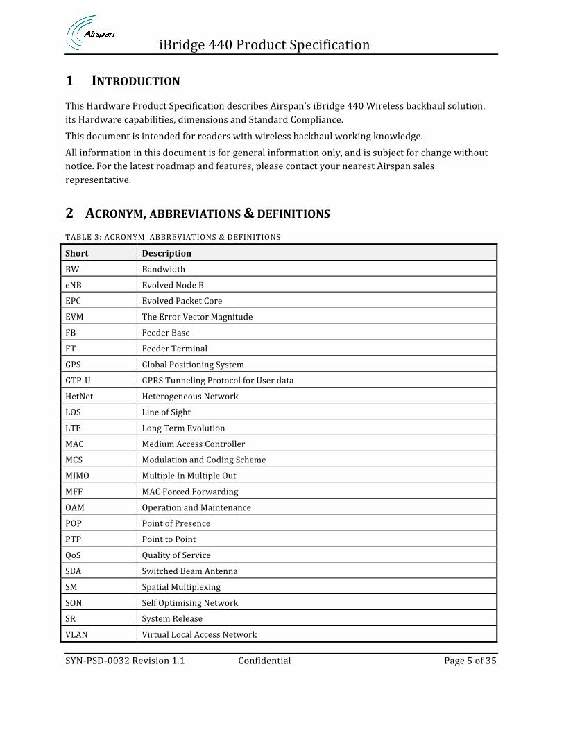
2 ACRONYM, ABBREVIATIONS & DEFINITIONS TABLE 3: ACRONYM, ABBREVIATIONS & DEFINITIONS
Short Description
BW Bandwidth
eNB Evolved Node B
EPC Evolved Packet Core
EVM The Error Vector Magnitude
FB Feeder Base
FT Feeder Terminal
GPS Global Positioning System
GTP-‐U GPRS Tunneling Protocol for User data
HetNet Heterogeneous Network
LOS Line of Sight
LTE Long Term Evolution
MAC Medium Access Controller
MCS Modulation and Coding Scheme
MIMO Multiple In Multiple Out
MFF MAC Forced Forwarding
OAM Operation and Maintenance
POP Point of Presence
PTP Point to Point
QoS Quality of Service
SBA Switched Beam Antenna
SM Spatial Multiplexing
SON Self Optimising Network
SR System Release
VLAN Virtual Local Access Network
iBridge 440 Product Specification
SYN-‐PSD-‐0032 Revision 1.1 Confidential Page 6 of 35
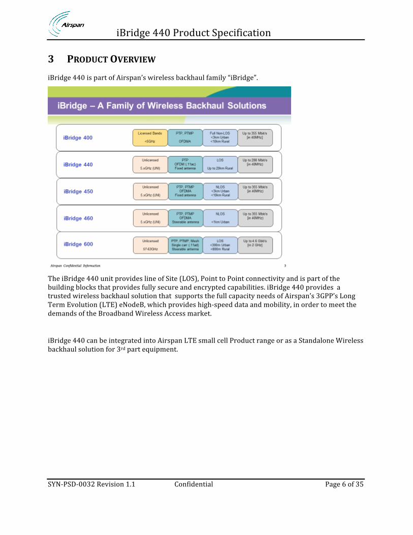
3 PRODUCT OVERVIEW iBridge 440 is part of Airspan’s wireless backhaul family “iBridge”.
The iBridge 440 unit provides line of Site (LOS), Point to Point connectivity and is part of the building blocks that provides fully secure and encrypted capabilities. iBridge 440 provides a trusted wireless backhaul solution that supports the full capacity needs of Airspan’s 3GPP’s Long Term Evolution (LTE) eNodeB, which provides high-‐speed data and mobility, in order to meet the demands of the Broadband Wireless Access market.
iBridge 440 can be integrated into Airspan LTE small cell Product range or as a Standalone Wireless backhaul solution for 3rd part equipment.

iBridge 440 Product Specification
SYN-‐PSD-‐0032 Revision 1.1 Confidential Page 7 of 35
3.1 SUPPORTED USE CASE iBridge 440 has been developed to supply a low cost LOS backhaul solution for small cell LTE ENBs that can be deployed and maintained using a low OPEX model. iBridge 440 is based on the IEEE 802.11ac specification and uses the 5GHz band to supply a unlicensed backhaul solution. 2 Examples of the backhaul solution can be seen in the diagrams below:
• Point to Point Link with a single sector ENB • Point to Point Link with a triple sector ENB
Point to Point Link with a single sector ENB Solution (panel or parabolic antenna)
IB440-‐221-‐P-‐0 / IB440-‐281-‐P-‐0
iBridge 440 Product Specification
SYN-‐PSD-‐0032 Revision 1.1 Confidential Page 8 of 35
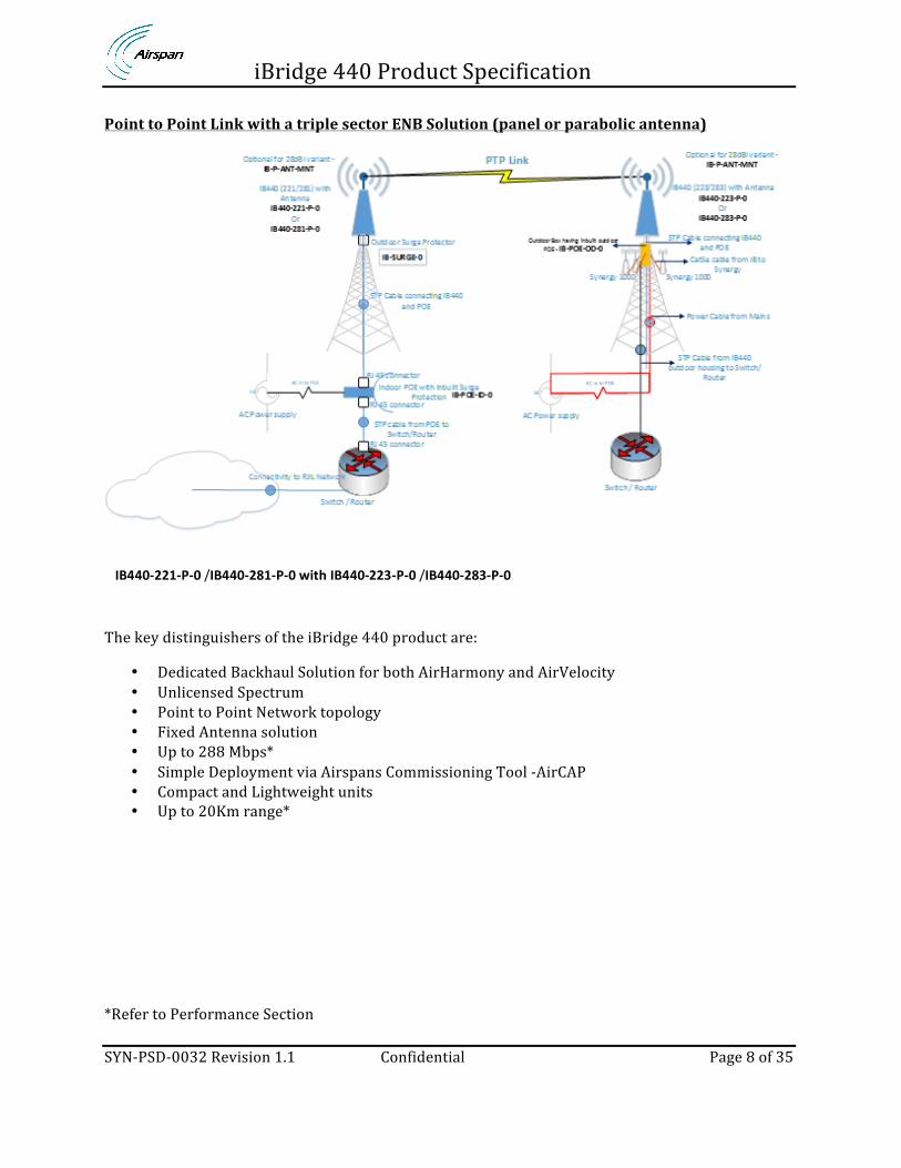
Point to Point Link with a triple sector ENB Solution (panel or parabolic antenna)
The key distinguishers of the iBridge 440 product are:
• Dedicated Backhaul Solution for both AirHarmony and AirVelocity • Unlicensed Spectrum • Point to Point Network topology • Fixed Antenna solution • Up to 288 Mbps* • Simple Deployment via Airspans Commissioning Tool -‐AirCAP • Compact and Lightweight units • Up to 20Km range*
*Refer to Performance Section
IB440-‐221-‐P-‐0 /IB440-‐281-‐P-‐0 with IB440-‐223-‐P-‐0 /IB440-‐283-‐P-‐0
iBridge 440 Product Specification
SYN-‐PSD-‐0032 Revision 1.1 Confidential Page 9 of 35
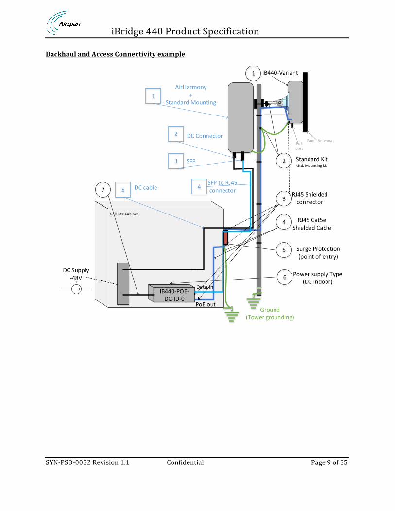
Backhaul and Access Connectivity example
Cell Site Cabinet
Panel AntennaPoEport
Standard Kit-‐Std. Mounting kit
Ground(Tower grounding)
IB440-‐Variant
RJ45 Cat5e Shielded Cable
Power supply Type(DC indoor)
Surge Protection(point of entry)
1
2
6
5
4
iB440-‐POE-‐DC-‐ID-‐0
RJ45 Shielded connector3
DC Supply-‐48V
AirHarmony+
Standard Mounting
DC Connector
SFP
SFP to RJ45connector
Data In
PoE out
DC
DC cable
1
2
3
457
iBridge 440 Product Specification
SYN-‐PSD-‐0032 Revision 1.1 Confidential Page 10 of 35
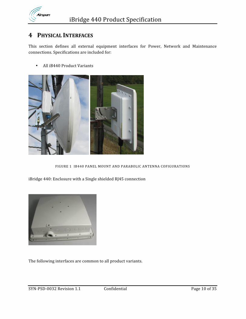
4 PHYSICAL INTERFACES This section defines all external equipment interfaces for Power, Network and Maintenance connections. Specifications are included for:
• All iB440 Product Variants
FIGURE 1 IB440 PANEL MOUNT AND PARABOLIC ANTENNA COFIGURATIONS
iBridge 440: Enclosure with a Single shielded RJ45 connection
The following interfaces are common to all product variants.
iBridge 440 Product Specification
SYN-‐PSD-‐0032 Revision 1.1 Confidential Page 11 of 35
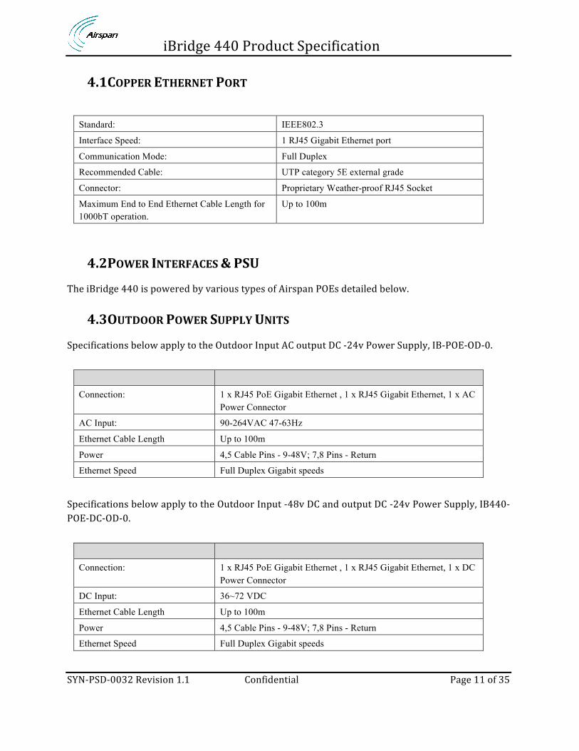
4.1 COPPER ETHERNET PORT
Standard: IEEE802.3
Interface Speed: 1 RJ45 Gigabit Ethernet port
Communication Mode: Full Duplex
Recommended Cable: UTP category 5E external grade
Connector: Proprietary Weather-proof RJ45 Socket
Maximum End to End Ethernet Cable Length for 1000bT operation.
Up to 100m
4.2 POWER INTERFACES & PSU The iBridge 440 is powered by various types of Airspan POEs detailed below.
4.3 OUTDOOR POWER SUPPLY UNITS Specifications below apply to the Outdoor Input AC output DC -‐24v Power Supply, IB-‐POE-‐OD-‐0.
Connection: 1 x RJ45 PoE Gigabit Ethernet , 1 x RJ45 Gigabit Ethernet, 1 x AC Power Connector
AC Input: 90-264VAC 47-63Hz
Ethernet Cable Length Up to 100m
Power 4,5 Cable Pins - 9-48V; 7,8 Pins - Return
Ethernet Speed Full Duplex Gigabit speeds
Specifications below apply to the Outdoor Input -‐48v DC and output DC -‐24v Power Supply, IB440-‐POE-‐DC-‐OD-‐0.
Connection: 1 x RJ45 PoE Gigabit Ethernet , 1 x RJ45 Gigabit Ethernet, 1 x DC Power Connector
DC Input: 36~72 VDC
Ethernet Cable Length Up to 100m
Power 4,5 Cable Pins - 9-48V; 7,8 Pins - Return
Ethernet Speed Full Duplex Gigabit speeds

iBridge 440 Product Specification
SYN-‐PSD-‐0032 Revision 1.1 Confidential Page 12 of 35
4.4 INDOOR POWER SUPPLY UNIT Specifications below apply to the Indoor Input AC output DC -‐24v Power Supply, IB-‐POE-‐ID-‐0.
Connection: 1 x RJ45 PoE Gigabit Ethernet , 1 x RJ45 Gigabit Ethernet, 1 x AC Power Connector
AC Input: 90-264VAC 47-63Hz
Ethernet Cable Length Up to 100m
Power 4,5 Cable Pins - 9-48V; 7,8 Pins - Return
Ethernet Speed Full Duplex Gigabit speeds
Specifications below apply to the Indoor Input -‐48v DC and output DC -‐24v Power Supply, IB440-‐POE-‐DC-‐ID-‐0
Connection: 1 x RJ45 PoE Gigabit Ethernet , 1 x RJ45 Gigabit Ethernet, 1 x DC Power Connector
DC Input: 36~72 VDC
Ethernet Cable Length Up to 100m
Power 4,5 Cable Pins - 9-48V; 7,8 Pins - Return
Ethernet Speed Full Duplex Gigabit speeds

iBridge 440 Product Specification
SYN-‐PSD-‐0032 Revision 1.1 Confidential Page 13 of 35
5 RADIO PERFORMANCE iBridge 440 supports a 2x2 RF Transceiver designed to operate MIMO and Diversity RF enhancement techniques for each RF interface. Each RF Transceiver is driven from a base-‐band Radio processor. This section specifies the RF performance:
5.1 FREQUENCY BAND SUPPORT
Airspan ID Uplink Range Downlink Range
A50c 5.825 to 5.875 GHz 5.825 to 5.875 GHz
5.2 RF CHANNEL BANDWIDTHS RF Channel bandwidths 20 & 40MHz are supported
5.3 SUPPORTED CHANNELS 6 channels to be supported in the available 50 Mhz
Channel ID Mode Centre Frequency Channel frequency range
1 Ce 5835 5825 MHz to 5865 MHz
2 Ce 5840 5830 MHz to 5870 MHz
3 Ce 5845 5835 MHz to 5875 MHz
4 eC 5855 5825 MHz to 5865 MHz
5 eC 5860 5830 MHz to 5870 MHz
6 eC 5865 5835 MHz to 5875 MHz
5.4 CHANNEL STEP 5 MHz Channel Steps are supported
5.5 TRANSMIT POWER The following maximum configurable transmit powers apply:
Frequency IB440-221-P-0 / IB440-281-P-0 IB440-223-P-0 / IB440-283-P-0
A50c 5.825 – 5.875Ghz Operating Frequency
Max power with 22dBi antenna option 14dBm
Max Power 28dBi antenna option 8dBm.
EIRP 36dBi 36dBi
iBridge 440 Product Specification
SYN-‐PSD-‐0032 Revision 1.1 Confidential Page 14 of 35
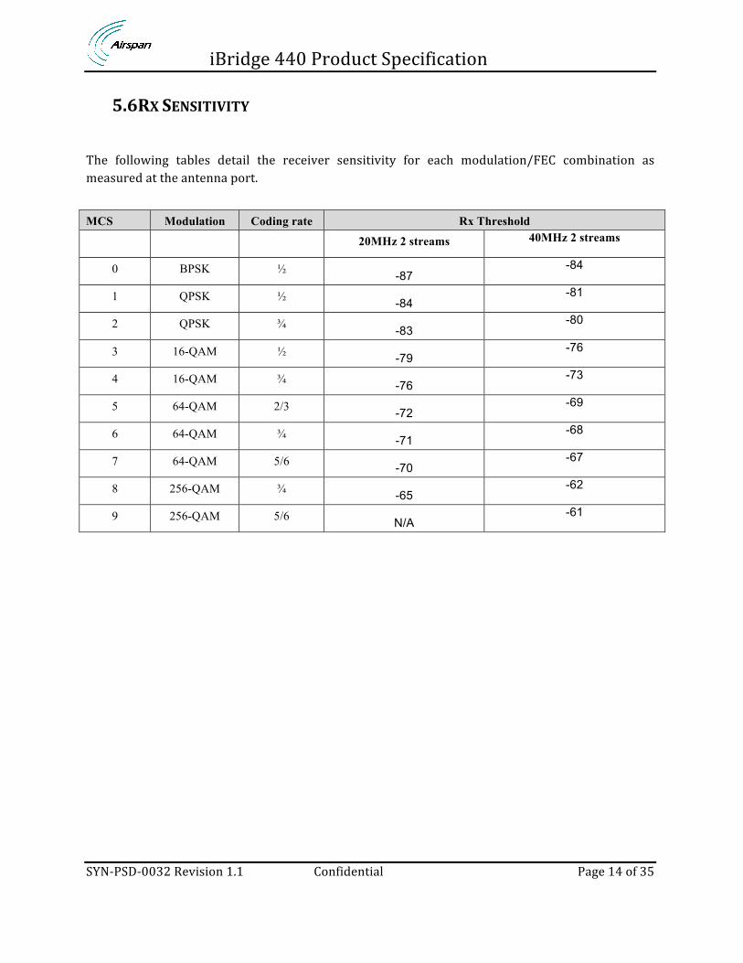
5.6 RX SENSITIVITY The following tables detail the receiver sensitivity for each modulation/FEC combination as measured at the antenna port. MCS Modulation Coding rate Rx Threshold
20MHz 2 streams 40MHz 2 streams
0 BPSK ½ -87 -84
1 QPSK ½ -84 -81
2 QPSK ¾ -83 -80
3 16-QAM ½ -79 -76
4 16-QAM ¾ -76 -73
5 64-QAM 2/3 -72 -69
6 64-QAM ¾ -71 -68
7 64-QAM 5/6 -70 -67
8 256-QAM ¾ -65 -62
9 256-QAM 5/6 N/A -61
iBridge 440 Product Specification
SYN-‐PSD-‐0032 Revision 1.1 Confidential Page 15 of 35
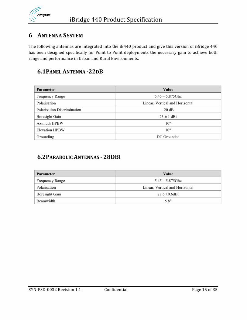
6 ANTENNA SYSTEM The following antennas are integrated into the iB440 product and give this version of iBridge 440 has been designed specifically for Point to Point deployments the necessary gain to achieve both range and performance in Urban and Rural Environments.
6.1 PANEL ANTENNA -‐22DB
Parameter Value
Frequency Range 5.45 – 5.875Ghz
Polarisation Linear, Vertical and Horizontal
Polarisation Discrimination -20 dB
Boresight Gain 23 ± 1 dBi
Azimuth HPBW 10°
Elevation HPBW 10°
Grounding DC Grounded
6.2 PARABOLIC ANTENNAS -‐ 28DBI
Parameter Value
Frequency Range 5.45 – 5.875Ghz
Polarisation Linear, Vertical and Horizontal
Boresight Gain 28.6 ±0.6dBi
Beamwidth 5.8°
iBridge 440 Product Specification
SYN-‐PSD-‐0032 Revision 1.1 Confidential Page 16 of 35
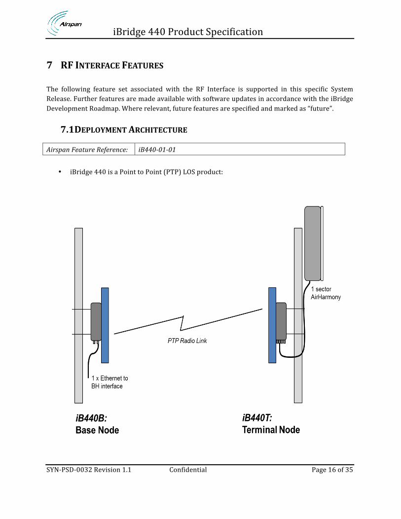
7 RF INTERFACE FEATURES The following feature set associated with the RF Interface is supported in this specific System Release. Further features are made available with software updates in accordance with the iBridge Development Roadmap. Where relevant, future features are specified and marked as “future”.
7.1 DEPLOYMENT ARCHITECTURE
Airspan Feature Reference: iB440-‐01-‐01
• iBridge 440 is a Point to Point (PTP) LOS product:

iBridge 440 Product Specification
SYN-‐PSD-‐0032 Revision 1.1 Confidential Page 17 of 35
7.2 CHANNEL PROFILES
Airspan Feature Reference: iB440-‐03-‐01
iBridge 440 supports the following channel bandwidth options, which are configurable from Netspan:
Channel ID Mode Centre Frequency Channel frequency range
1 Ce 5835 5825 MHz to 5865 MHz
2 Ce 5840 5830 MHz to 5870 MHz
3 Ce 5845 5835 MHz to 5875 MHz
4 eC 5855 5825 MHz to 5865 MHz
5 eC 5860 5830 MHz to 5870 MHz
6 eC 5865 5835 MHz to 5875 MHz
7.3 OFDM PERMUTATIONS
Airspan Feature Reference: iB440-‐04-‐01
iBridge 440 supports the following OFDM permutations as defined in the IEEE 802.11ac LOS standard: 802.11ac divides the channel into OFDM subcarriers, each of which has a bandwidth of 312.5 kHz. Each of the subcarriers is used as an independent transmission, and OFDM distributes the incoming data bits among the subcarriers. A few subcarriers are reserved and are called pilot carriers; they do not carry user data and instead are used to measure the channel.
iBridge 440 Product Specification
SYN-‐PSD-‐0032 Revision 1.1 Confidential Page 18 of 35
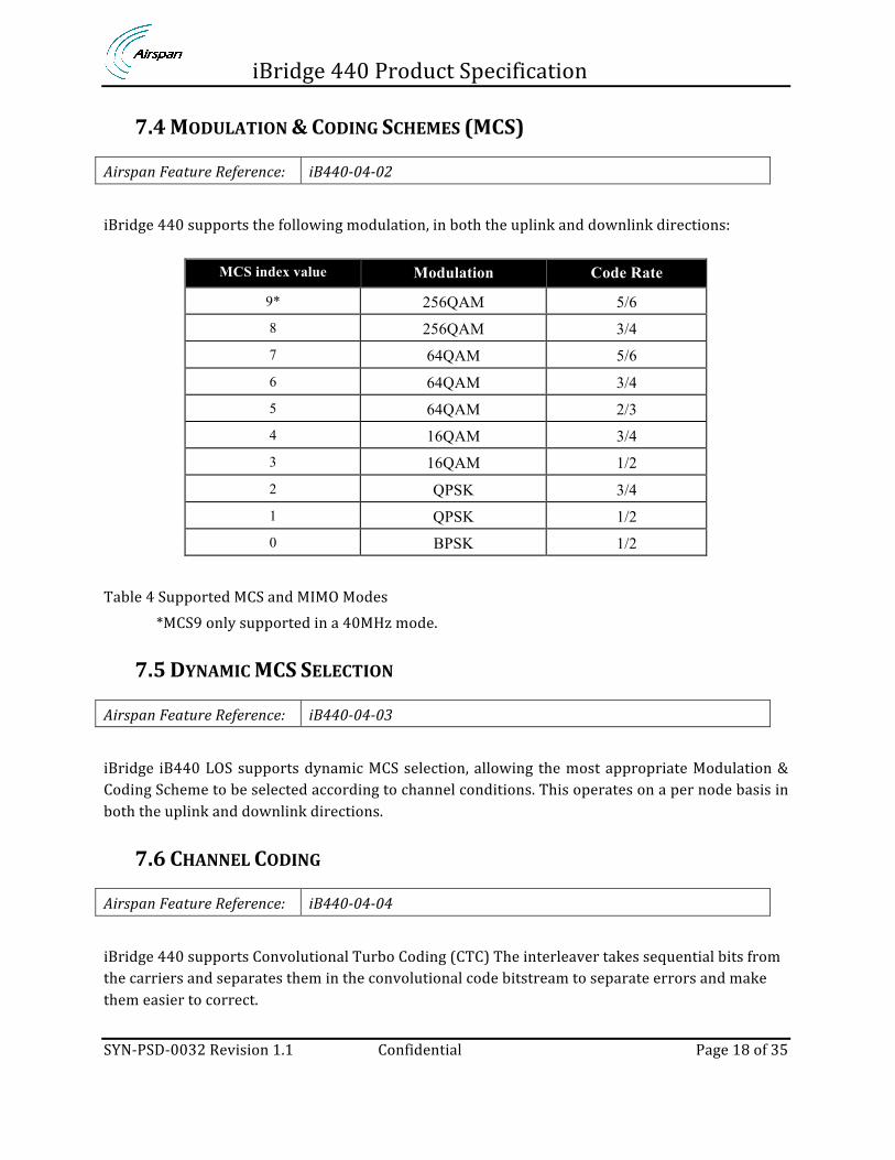
7.4 MODULATION & CODING SCHEMES (MCS)
Airspan Feature Reference: iB440-‐04-‐02
iBridge 440 supports the following modulation, in both the uplink and downlink directions:
MCS index value Modulation Code Rate
9* 256QAM 5/6 8 256QAM 3/4 7 64QAM 5/6 6 64QAM 3/4 5 64QAM 2/3 4 16QAM 3/4 3 16QAM 1/2 2 QPSK 3/4 1 QPSK 1/2 0 BPSK 1/2
Table 4 Supported MCS and MIMO Modes
*MCS9 only supported in a 40MHz mode.
7.5 DYNAMIC MCS SELECTION
Airspan Feature Reference: iB440-‐04-‐03
iBridge iB440 LOS supports dynamic MCS selection, allowing the most appropriate Modulation & Coding Scheme to be selected according to channel conditions. This operates on a per node basis in both the uplink and downlink directions.
7.6 CHANNEL CODING
Airspan Feature Reference: iB440-‐04-‐04
iBridge 440 supports Convolutional Turbo Coding (CTC) The interleaver takes sequential bits from the carriers and separates them in the convolutional code bitstream to separate errors and make them easier to correct.

iBridge 440 Product Specification
SYN-‐PSD-‐0032 Revision 1.1 Confidential Page 19 of 35
8 QUALITY OF SERVICE The following feature set associated with the QoS is supported in this specific System Release. Further features are made available with software updates in accordance with the iBridge Development Roadmap. Where relevant, future features are specified and marked as “future”.
8.1 SIMPLE QUEUES Ibridge 440 uses simple queues to build advanced QoS applications. iBridge 440 uses multiple packet marks from /ip firewall mangle to create a QOS to interact with the ENB. The process marks packets for future processing with special marks. They identify a packet based on its mark and process it accordingly. The mangle marks exist only within the router, they are not transmitted across the network. iBridge 440 uses fields in the IP header, like TOS (DSCP) and TTL fields.
iBridge 440 Product Specification
SYN-‐PSD-‐0032 Revision 1.1 Confidential Page 20 of 35
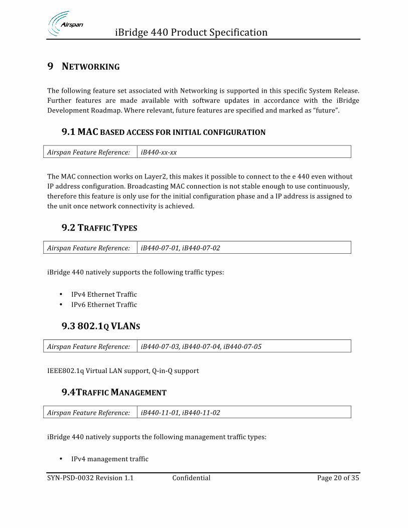
9 NETWORKING The following feature set associated with Networking is supported in this specific System Release. Further features are made available with software updates in accordance with the iBridge Development Roadmap. Where relevant, future features are specified and marked as “future”.
9.1 MAC BASED ACCESS FOR INITIAL CONFIGURATION
Airspan Feature Reference: iB440-‐xx-‐xx
The MAC connection works on Layer2, this makes it possible to connect to the e 440 even without IP address configuration. Broadcasting MAC connection is not stable enough to use continuously, therefore this feature is only use for the initial configuration phase and a IP address is assigned to the unit once network connectivity is achieved.
9.2 TRAFFIC TYPES
Airspan Feature Reference: iB440-‐07-‐01, iB440-‐07-‐02
iBridge 440 natively supports the following traffic types:
• IPv4 Ethernet Traffic • IPv6 Ethernet Traffic
9.3 802.1Q VLANS
Airspan Feature Reference: iB440-‐07-‐03, iB440-‐07-‐04, iB440-‐07-‐05
IEEE802.1q Virtual LAN support, Q-‐in-‐Q support
9.4 TRAFFIC MANAGEMENT
Airspan Feature Reference: iB440-‐11-‐01, iB440-‐11-‐02
iBridge 440 natively supports the following management traffic types:
• IPv4 management traffic

iBridge 440 Product Specification
SYN-‐PSD-‐0032 Revision 1.1 Confidential Page 21 of 35
• IPv6 management Traffic

iBridge 440 Product Specification
SYN-‐PSD-‐0032 Revision 1.1 Confidential Page 22 of 35
10 SECURITY The following feature set associated with Security is supported in this specific System Release. Further features are made available with software updates in accordance with the iBridge 440 Development Roadmap. Where relevant, future features are specified and marked as “future”.
10.1 AUTHENTICATION AND ENCRYPTION
Airspan Feature Reference: iB440-‐08-‐03
iB440-‐security provides authentication and data encryption capabilities to the wireless links. iB440 implements Authentication of peer nodes (iB440 Base and iB440 Terminals) using preshared key and data encryption using AES-‐CCM with 128 bit keys which are derived from the preshared key. Default configuration enables iB440-‐secure mode which will block any non-‐secured communication. A preshared key is burned into iB440 units in secured factory environment and can be altered or modified by authorised Airspan personnel.
10.2 PASSWORD MANAGEMENT
Airspan Feature Reference: iB440-‐08-‐06
iBridge 440 supports password controlled access, with encrypted storage of a hash of the password for additional security.

iBridge 440 Product Specification
SYN-‐PSD-‐0032 Revision 1.1 Confidential Page 23 of 35
11 OPERATIONS, ADMINISTRATION & MANAGEMENT (OAM) The following feature set associated with O&M is supported in this specific System Release. Further features are made available with software updates in accordance with the iBridge 440 Development Roadmap. Where relevant, future features are specified and marked as “future”.
11.1 MANAGEMENT ARCHITECTURE
iBridge 440 supports both indirect and direct management connections. Direct management connections are achieved with an SNMP client operating on each iBridge node, allowing independent control of each node. Indirect management connections are supported on Termination nodes, with an SNMP client operating on the Base node. Management connectivity is effectively hosted by the Base nodes for all connected nodes, minimizing the number of SNMP clients across the network, and reducing management traffic.
11.2 MANAGEMENT PROTOCOL
Airspan Feature Reference: iB440-‐11-‐01
iBridge 440 supports management connectivity of the iBridge interface using SNMP over IPv4. Management to the Feeder Base is via the network port. Management to the Feeder Terminal is over the air via its associated Feeder Base. iBridge 440 management traffic can be tagged with a VLAN tag to differentiate from other traffic.
11.3 EMS DISCOVERY
Airspan Feature Reference: iB440-‐11-‐08
iBridge 440 supports manual configuration of the EMS, or automated detection of the EMS system.
11.4 INSTALLATION AND COMMISSIONING
iBridge 440 supports Airspan’s Field Commissioning Application “AirCAP”. AirCAP is used to commission and align Point to Point iBridge links, the application is primarily used by commission teams to align panel antenna and optimized the backhaul link.

iBridge 440 Product Specification
SYN-‐PSD-‐0032 Revision 1.1 Confidential Page 24 of 35
11.5 CONFIGURATION MANAGEMENT
iBridge 440 supports configuration from Netspan using SNMP, including the following:
• Configurable frequency • Ability to disable transmitter • Configure QOS
11.6 INVENTORY MANAGEMENT
iBridge 440 provides inventory information to Netspan.
11.7 FAULT MANAGEMENT
iBridge 440 supports fault management from Netspan, providing SNMP trap notifications to include different alarms and events. iBridge 440 allows multiple SNMP destinations to be defined, allowing faults to be tracked by different management systems.
11.8 PERFORMANCE MANAGEMENT
iBridge 440 supports performance management from Netspan*Roadmap item
11.9 SOFTWARE MANAGEMENT
iBridge 440 supports remote software management and status reporting using Netspan. The following protocols are supported when downloading software from the network:
• TFTP • SFTP
Generic software package is used for both FB and FT operation, operating mode is selected during commissioning mode or via configuration.

iBridge 440 Product Specification
SYN-‐PSD-‐0032 Revision 1.1 Confidential Page 25 of 35
iBridge 440 Product Specification
SYN-‐PSD-‐0032 Revision 1.1 Confidential Page 26 of 35
12 PERFORMANCE
12.1 SYSTEM THROUGHPUT
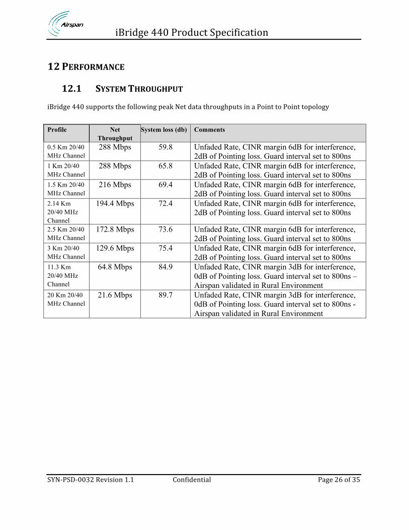
iBridge 440 supports the following peak Net data throughputs in a Point to Point topology Profile Net
Throughput System loss (db) Comments
0.5 Km 20/40 MHz Channel
288 Mbps 59.8 Unfaded Rate, CINR margin 6dB for interference, 2dB of Pointing loss. Guard interval set to 800ns
1 Km 20/40 MHz Channel
288 Mbps 65.8 Unfaded Rate, CINR margin 6dB for interference, 2dB of Pointing loss. Guard interval set to 800ns
1.5 Km 20/40 MHz Channel
216 Mbps 69.4 Unfaded Rate, CINR margin 6dB for interference, 2dB of Pointing loss. Guard interval set to 800ns
2.14 Km 20/40 MHz Channel
194.4 Mbps 72.4 Unfaded Rate, CINR margin 6dB for interference, 2dB of Pointing loss. Guard interval set to 800ns
2.5 Km 20/40 MHz Channel
172.8 Mbps 73.6 Unfaded Rate, CINR margin 6dB for interference, 2dB of Pointing loss. Guard interval set to 800ns
3 Km 20/40 MHz Channel
129.6 Mbps 75.4 Unfaded Rate, CINR margin 6dB for interference, 2dB of Pointing loss. Guard interval set to 800ns
11.3 Km 20/40 MHz Channel
64.8 Mbps 84.9 Unfaded Rate, CINR margin 3dB for interference, 0dB of Pointing loss. Guard interval set to 800ns – Airspan validated in Rural Environment
20 Km 20/40 MHz Channel
21.6 Mbps 89.7 Unfaded Rate, CINR margin 3dB for interference, 0dB of Pointing loss. Guard interval set to 800ns - Airspan validated in Rural Environment

iBridge 440 Product Specification
SYN-‐PSD-‐0032 Revision 1.1 Confidential Page 27 of 35
Unfaded Rate, CINR margin 6dB for interference, 2dB of pointing loss. Guard interval set to 800ns
Unfaded Rate, CINR margin 3dB for interference, 0dB of pointing loss. Guard interval set to 800ns
0
50
100
150
200
250
300
350
0 5000 10000 15000 20000 25000
Rate -‐ Mb/s
Distance -‐ m
iB440 Aggregate Link Rate Unfaded Rate Faded Rate, 99 % availability Faded Rate, 99.9 % availability Faded Rate, 99.99 % availability
0
50
100
150
200
250
300
350
0 5000 10000 15000 20000 25000
Rate -‐ Mb/s
Distance -‐ m
iB440 Aggregate Link Rate
Unfaded Rate Faded Rate, 99 % availability Faded Rate, 99.9 % availability Faded Rate, 99.99 % availability
iBridge 440 Product Specification
SYN-‐PSD-‐0032 Revision 1.1 Confidential Page 28 of 35
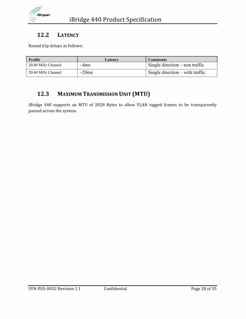
12.2 LATENCY
Round trip delays as follows: Profile Latency Comments 20/40 MHz Channel ~4ms Single direction – non traffic 20/40 MHz Channel ~20ms Single direction – with traffic
12.3 MAXIMUM TRANSMISSION UNIT (MTU)
iBridge 440 supports an MTU of 2028 Bytes to allow VLAN tagged frames to be transparently passed across the system.

iBridge 440 Product Specification
SYN-‐PSD-‐0032 Revision 1.1 Confidential Page 29 of 35
13 PHYSICAL CHARACTERISTICS AND POWER
13.1 HARDWARE CONFIGURATIONS
This specification details the system when running iBridge 11ac software. iBridge 440 is available in 2 form factors using the same core internal components the variants are as follows:
• 22dBi ANTENNA / 11˚ / 305MM PANEL • 28dBi ANTENNA / 5.8˚ / 650MM PARABOLIC
Common configurations are outlined in the following section. Other configurations using a mixture of antenna configuration may be supported and Airspan Product Management should be consulted for more details.
FIG 4 IB440 PANEL MOUNT ANTENNA UNIT
This configuration is targeted for LOS deployments where the Feeder Base is located on pole mounts normally on towers or building location. RF Transceiver Configuration: 2Tx 2Rx
Number of RF Channels Supported: 1
Frequency Band 5.825 to 5.875 GHz Operating Frequency
iBridge 440 Product Specification
SYN-‐PSD-‐0032 Revision 1.1 Confidential Page 30 of 35
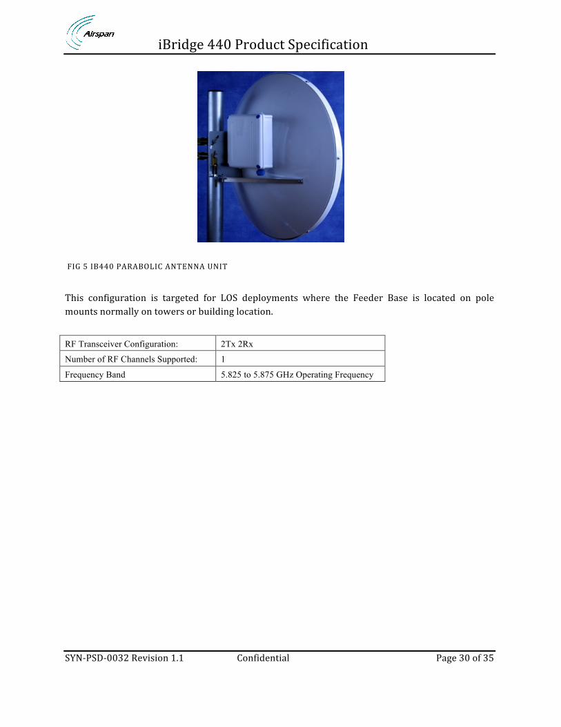
FIG 5 IB440 PARABOLIC ANTENNA UNIT
This configuration is targeted for LOS deployments where the Feeder Base is located on pole mounts normally on towers or building location. RF Transceiver Configuration: 2Tx 2Rx
Number of RF Channels Supported: 1
Frequency Band 5.825 to 5.875 GHz Operating Frequency

iBridge 440 Product Specification
SYN-‐PSD-‐0032 Revision 1.1 Confidential Page 31 of 35
13.2 INTEGRATING WITH ACCESS NETWORK
iBridge 440 Feeder Terminals support a single physical integration with the access network:
1. Loose Integration: An iBridge 440 Node can be physically mounted near an AirHarmony LTE eNB using standard mounting brackets(example configuration below)
FIG 6IB440 TERMINAL NODE LOOSE INTEGRATION

iBridge 440 Product Specification
SYN-‐PSD-‐0032 Revision 1.1 Confidential Page 32 of 35
13.3 MECHANICAL SPECIFICATION
The following physical specifications apply to units using the standard Universal pole mounting bracket.
13.4 DIMENSIONS
Description Dimensions
IB440-221-P-0 305 x 305 x 75mm
IB440-223-P-0 305 x 305 x 75mm
IB440-281-P-0 650 x 650 x 180mm
IB440-283-P-0 650 x 650 x 180mm
13.5 OUTDOOR POWER SUPPLY
Description Dimensions
AC Outdoor power supply unit (IB-POE-OD-0). 250 x 200 x 100mm
DC Outdoor power supply unit (IB440-POE-OD-0).
255 x 200 x 74mm
13.6 INDOOR POWER SUPPLY
Description Dimensions
AC Indoor power supply unit (IB-POE-ID-0). 125 x 75 x 38mm
DC Indoor power supply unit (IB440-POE-ID-0). 180 x 117 x 36mm
13.7 WEIGHTS
13.7.1 IBRIDGE 440 WEIGHTS
Description Unpackaged Packaged
IB440-221-P-0 3kg 5kg
IB440-223-P-0 3kg 5kg
IB440-281-P-0 8.5Kg TBD
IB440-283-P-0 8.5Kg TBD

iBridge 440 Product Specification
SYN-‐PSD-‐0032 Revision 1.1 Confidential Page 33 of 35
13.7.2 ACCESSORY WEIGHTS
Description Unpackaged Packaged
IB-SURGE-0 (Outdoor Ethernet surge protector) 220g TBD
AC Indoor power supply unit (IB-POE-ID-0). 300g TBD
DC Indoor power supply unit (IB440-POE-ID-0). 2kg TBD
AC Outdoor power supply unit (IB-POE-OD-0). 3kg TBD
DC Outdoor power supply unit (IB440-POE-OD-0). 2.5kg TBD
13.8 MOUNTING BRACKETS
iBridge is 440 to mount on poles. There are two bracket options as follows: Description Unpackaged Packaged
Universal Pole Mounting Bracket 0.820kg
Precision Mounting Bracket 3.5kg
13.9 POWER CONSUMPTION
Max Power Consumption (with 24V Input):
Description
IB440-221-P-0 / IB440-281-P-0 13W max power consumption
IB440-223-P-0 / IB440-283-P-0 20W max power consumption

iBridge 440 Product Specification
SYN-‐PSD-‐0032 Revision 1.1 Confidential Page 34 of 35
14 STANDARDS COMPLIANCE
14.1 ENVIRONMENTAL
This section details the environmental performance that iB440 complies to:
IP Rating: IP67
Operating Ambient Temperature: -40 to +55degC
Operating Humidity: ETS 300 019-1-4,EN 302 085 (Annex A.1.1)
Salt Mist: According to IEC 68-2-11
Wind Loading 200 Km/h (Survival)
14.2 EMC
iBridge 440 is compliant with the following EMC standards ETSI EN 301 489-‐1 V1.9.2 (2011-‐09) Class A, as well as EN 301 489-‐4 V1.4.1 (2009-‐05).
14.3 LIGHTNING / SURGE PROTECTION
iBridge 440 is compliant with the following Surge protection standards:
Surge Handling 8/20uS (5kA)
Antenna Ports DC Grounded
14.4 ELECTROSTATIC DISCHARGE
All ports meet the ESD requirements of EN61000 4-‐2. The test condition is level 3 for air discharge and level 2 for contact discharge.

iBridge 440 Product Specification
SYN-‐PSD-‐0032 Revision 1.1 Confidential Page 35 of 35
14.5 SAFETY
iBridge 440 conforms to IEC 60950, UL 60950, EN 60950-‐1:2006 and EN 60950-‐22:2006. In addition to this specification, the following specifications covering human exposure to radio frequency electromagnetic fields are also met:
• EN 50385:2002 Product standard to demonstrate the compliances of radio base stations and fixed terminal stations for wireless telecommunication systems with the basic restrictions or the reference levels related to human exposure to radio frequency electromagnetic fields (110 -‐ 40 GHz). General public
• EN 50401:2006 Product standard to demonstrate the compliance of fixed equipment for radio transmission (110 -‐ 40 GHz) intended for use in wireless telecommunication networks with the basic restrictions or the reference levels related to general public exposure to radio frequency electromagnetic fields, when put into service
14.6 ROHS & WEE COMPLIANCE
• The chemical content of the equipment and its packaging meets the EU ROHS directive -‐ 2002/95/EC (ROHS) – compliant with ROHS6 (up to 2009)
• The WEEE symbol is present on the product label as per the requirements of European directive 2002/96/EC
14.7 RELIABILITY
The following reliability data assumes worst case requirements. Overall reliability is improved when considering the dual transceivers as a redundancy factor (this consideration is not included in the quoted figures. Average Mean Time Between Failures (MTBF) = 25 years