ic-f3102d/f3103d/f4102d/f4103d series instruction · pdf filethis instruction manual includes...
TRANSCRIPT

INSTRUCTION MANUAL
iF3103D
VHF dPMR HANDHELD TRANSCEIVER
iF3102D
The photo shows the VHF transceiver.
iF4103D
UHF dPMR HANDHELD TRANSCEIVER
iF4102D
i
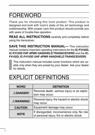
FOREWORDThank you for choosing this Icom product. This product is designed and built with Icom’s state of the art technology and craftsmanship. With proper care this product should provide you with years of trouble-free operation.
READ ALL INSTRUCTIONS carefully and completely before using the transceiver.
SAVE THIS INSTRUCTION MANUAL— This instruction manual contains important operating instructions for the IC-F3102D, IC-F3103D VHF dPMR HANDHELD TRANSCEIVERS and the IC-F4102D, IC-F4103D UHF dPMR HANDHELD TRANSCEIVERS.
This instruction manual includes some functions which are us-able only when they are preset by your dealer. Ask your dealer for details.
EXPLICIT DEFINITIONS
WORD DEFINITION
RDANGER!Personal death, serious injury or an explo-sion may occur.
RWARNING!Personal injury, fire hazard or electric shock may occur.
CAUTION Equipment damage may occur.
NOTEIf disregarded, inconvenience only. No risk of personal injury, fire or electric shock.

ii
Icom, Icom Inc. and Icom logo are registered trademarks of Icom Incorporated (Japan) in Japan, the United States, the United Kingdom, Germany, France, Spain, Russia, Australia, New Zealand, and/or other countries.IDAS is trademark of Icom Incorporated (Japan).dPMR and the dPMR logo are trademarks of the dPMR MoU Association.All other products or brands are registered trademarks or trademarks of their re-spective holders.
VOICE CODING TECHNOLOGYThe AMBE+2™ voice coding Technology embodied in this product is protected by intellectual property rights including patent rights, copyrights and trade secrets of Digital Voice Systems, Inc. This voice coding Technology is licensed solely for use within this Com-munications Equipment. The user of this Technology is explicitly prohibited from attempting to extract, remove, decompile, reverse engineer, or disassemble the Object Code, or in any other way convert the Object Code into a human-readable form. U.S. Patent Nos.#5,870,405, #5,826,222, #5,754,974, #5,701,390, #5,715,365,#5,649,050, #5,630,011, #5,581,656, #5,517,511, #5,491,772,#5,247,579, #5,226,084 and #5,195,166.
Icom is not responsible for the destruction or damage to the Icom transceiver, if the malfunction is because of:• Force majeure, including, but not limited to, fires, earthquakes,
storms, floods, lightnings, or other natural disasters, disturbanc-es, riots, war, or radioactive contamination.
• The use of Icom transceiver with any equipment that is not man-ufactured or approved by Icom.

iii
PRECAUTIONSR DANGER! NEVER short terminals of the battery pack. Also, current may flow into nearby metal objects such as a necklace, so be careful when placing battery packs (or the transceiver) in hand-bags, etc. Simply carrying with or placing near metal objects such as a necklace, etc. may cause shorting. This may damage not only the battery pack, but also the transceiver.
R DANGER! Use and charge only specified Icom battery packs with Icom transceivers or Icom chargers. Only Icom battery packs are tested and approved for use with Icom transceivers or charged with Icom chargers. Using third-party or counterfeit battery packs or chargers may cause smoke, fire, or cause the battery to burst.
R WARNING! NEVER hold the transceiver so that the antenna is very close to, or touching exposed parts of the body, especially the face or eyes, while transmitting. The transceiver will perform best if the microphone is 5 to 10 cm away from the lips and the transceiver is vertical.
R WARNING! NEVER operate the transceiver with a headset or other audio accessories at high volume levels. The continuous high volume operation may cause a ringing in your ears. If you ex-perience the ringing, reduce the volume level or discontinue use.
R WARNING! NEVER operate the transceiver while driving a vehicle. Safe driving requires your full attention—anything less may result in an accident.
CAUTION: MAKE SURE the flexible antenna, battery pack, and jack cover are securely attached to the transceiver, and that the antenna and battery pack are dry before attachment. Exposing the inside of the transceiver to dust or water will result in serious damage to the transceiver.

iv
PRECAUTIONSDO NOT operate the transceiver near unshielded electrical blast-ing caps or in an explosive atmosphere.
DO NOT push [PTT] when you do not actually intend to transmit.
DO NOT operate or place the transceiver in direct sunlight or in areas with temperatures below –25°C or above +55°C.
DO NOT modify the transceiver. The specifications may change and then not comply with the requirements of a corresponded regulation. The transceiver warranty does not cover any problems caused by unauthorized modification.
DO NOT use harsh solvents such as benzine or alcohol when cleaning, as they will damage the transceiver surfaces.
BE CAREFUL! The transceiver will become hot when operating it continuously for long periods of time.
KEEP the transceiver away from heavy rain, and never immerse it in the water. The transceiver meets IP54* requirements for dust-protection and splash resistance. However, once the transceiver has been dropped, dust-protection and splash resistance cannot be guaranteed because of possible damage to the transceiver’s case or the waterproof seal.* Only when the battery pack/case and jack cover are attached.
MAKE SURE to turn OFF the transceiver before connecting or disconnecting the supplied or optional accessory.
v
TABLE OF CONTENTSFOREWORD ........................................................................................ iEXPLICIT DEFINITIONS ...................................................................... iVOICE CODING TECHNOLOGY ........................................................ iiPRECAUTIONS .............................................................................. iii, iv
1 ACCESSORIES ......................................................................... 1–4 ■ Supplied accessories .................................................................. 1 ■ Accessory attachments .............................................................. 1
2 PANEL DESCRIPTION ............................................................ 5–13 ■ Front, top and side panels .......................................................... 5 ■ LED indicator .............................................................................. 7 ■ Programmable function keys .................................................... 10
3 BASIC OPERATION .............................................................. 14–26 ■ Turning ON the power ............................................................... 14 ■ Channel selection ..................................................................... 15 ■ Call procedure .......................................................................... 16 ■ Receiving and transmitting ....................................................... 17 ■ Setting the microphone gain ..................................................... 20 ■ Setting the squelch level ........................................................... 21 ■ Setting the Beep level ............................................................... 22 ■ Setting the Ringer level ............................................................. 23 ■ Output power level selection ..................................................... 24 ■ Priority A channel selection ...................................................... 24 ■ Lone Worker Emergency Call ................................................... 25 ■ Emergency Call ........................................................................ 26

vi
1
2
3
4
5
6
7
8
9
10
11
12
13
14
15
16
17
18
19
20
4 dPMR OPERATION ............................................................... 27–32 ■ dPMR operation ........................................................................ 27 ■ Receiving a call......................................................................... 28 ■ Transmitting a call ..................................................................... 30 ■ Position data transmission ........................................................ 32 ■ Status message transmission ................................................... 32 ■ Scrambler function .................................................................... 32
5 BATTERY CHARGING .......................................................... 33–43 ■ Caution (for the BP-264 ni-mh battery).................................... 33 ■ Caution (for the BP-265 Li-ion battery) ................................... 35 ■ Battery chargers ....................................................................... 38
6 BATTERY CASE .......................................................................... 44 ■ Optional battery case (BP-263) ................................................ 44
7 OPTIONS ............................................................................... 45–50 ■ VOX function ............................................................................. 48
8 INFORMATION ............................................................................ 51 ■ Country code list ....................................................................... 51 ■ Disposal .................................................................................... 52
TABLE OF CONTENTS

■ Accessory attachmentsD Flexible antennaConnect the flexible antenna to the an-tenna connector.
CAUTION:• NEVER carry the transceiver by
holding the antenna.• DO NOT connect the antenna
other than listed above.• Transmitting without an antenna will
damage the transceiver.
■ Supplied accessoriesThe following accessories are supplied with the transceiver.
1
1 ACCESSORIES
Battery pack*
Belt clip* Jack cover(with screws)
Battery charger* Power adapter*
* Not supplied, or the shape is different, depending on the version.
Flexible antenna(This illustration is for the VHF type.)
2
1ACCESSORIES
1
2
3
4
5
6
7
8
9
10
11
12
13
14
15
16
17
18
19
20
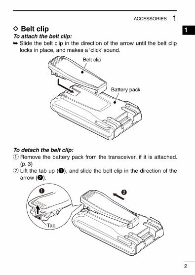
D Belt clipTo attach the belt clip:➥ Slide the belt clip in the direction of the arrow until the belt clip
locks in place, and makes a ‘click’ sound.
Battery pack
Belt clip
To detach the belt clip:q Remove the battery pack from the transceiver, if it is attached.
(p. 3)w Lift the tab up (q), and slide the belt clip in the direction of the
arrow (w).
wq
Tab
3
1 ACCESSORIES
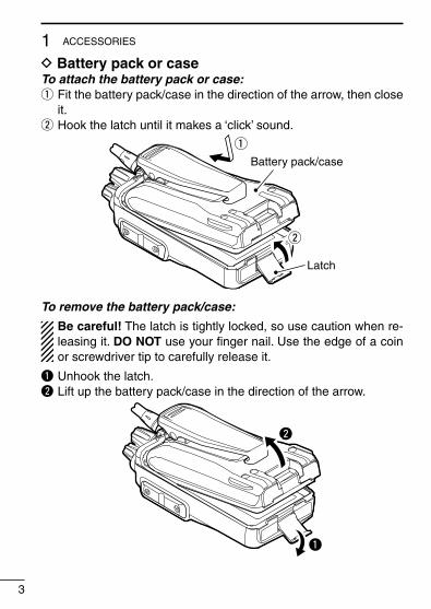
D Battery pack or caseTo attach the battery pack or case:q Fit the battery pack/case in the direction of the arrow, then close
it.w Hook the latch until it makes a ‘click’ sound.
q
Latch
w
Battery pack/case
To remove the battery pack/case:
Be careful! The latch is tightly locked, so use caution when re-leasing it. DO NOT use your finger nail. Use the edge of a coin or screwdriver tip to carefully release it.
q Unhook the latch.w Lift up the battery pack/case in the direction of the arrow.
q
w
4
1ACCESSORIES
1
2
3
4
5
6
7
8
9
10
11
12
13
14
15
16
17
18
19
20
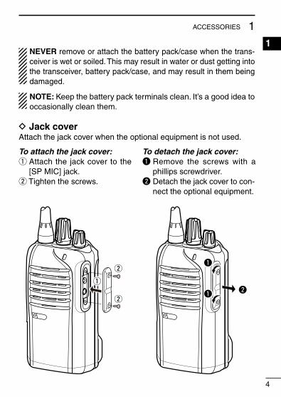
NEVER remove or attach the battery pack/case when the trans-ceiver is wet or soiled. This may result in water or dust getting into the transceiver, battery pack/case, and may result in them being damaged.
NOTE: Keep the battery pack terminals clean. It’s a good idea to occasionally clean them.
D Jack coverAttach the jack cover when the optional equipment is not used.
To attach the jack cover:q Attach the jack cover to the
[SP MIC] jack.w Tighten the screws.
To detach the jack cover:q Remove the screws with a
phillips screwdriver.w Detach the jack cover to con-
nect the optional equipment.
w
w
w
q
q
q

5
2 PANEL DESCRIPTION■ Front, top and side panels
Microphone
Speaker
r
w
e
q
y
u
i
tLOWER KEY
UPPER KEY
PTT SWITCH
ANTENNACONNECTOR
ROTARYSELECTOR
LED INDICATOR
VOLUMECONTROL
SPEAKER-MICROPHONEJACK
q ROTARY SELECTOR Rotate to select the pre-programmed memory channels or scan
lists, depending on the pre-programming.
w VOLUME CONTROL [VOL] Rotate to turn the power ON or OFF, and adjust the audio level.

6
2PANEL DESCRIPTION
e LED INDICATOR (pp. 7–9) ➥ Lights red* while transmitting. * When the optional battery case is attached, the LED indicator
lights orange. ➥ Lights green while receiving a signal, or when the squelch is
open. ➥ Lights/blinks orange when the matched 2/5-tone code is re-
ceived, depending on the presetting. See pages 7–9 for details.
r SPEAKER-MICROPHONE JACK [SP MIC] Connect the optional speaker-microphone or VOX adapter
cable.
t LOWER KEY [Lower]y UPPER KEY [Upper] The desired function can be assigned by your dealer. (p. 10)
u PTT SWITCH [PTT] Hold down to transmit; release to receive.
i ANTENNA CONNECTOR Connect the antenna.
1
2
3
4
5
6
7
8
9
10
11
12
13
14
15
16
17
18
19
20
Jack cover
NOTE: Attach the jack cover when the optional equipment is not used. (p. 4)
7
2 PANEL DESCRIPTION
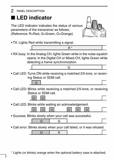
■ LED indicatorThe LED indicator indicates the status of various parameters of the transceiver as follows;(Reference: R=Red, G=Green, O=Orange)
* Lights (or blinks) orange when the optional battery case is attached.
• TX: Lights Red while transmitting a signal.
R *
• RX busy: In the Analog CH, lights Green while in the noise squelch opens. In the Digital CH or Mixed CH, lights Green while detecting a frame synchronization.
G
• Call LED: Turns ON while receiving a matched 2/5-tone, or receiv-ing Status or SDM call.
O
• Call LED: Blinks while receiving a matched 2/5-tone, or receiving Status or SDM call.
O O
• Call LED: Blinks while waiting an acknowledgement.
O O O O O O
• Success: Blinks slowly when your call was successful.
O G
• Call error: Blinks slowly when your call failed, or it was refused.
O R
8
2PANEL DESCRIPTION
1
2
3
4
5
6
7
8
9
10
11
12
13
14
15
16
17
18
19
20
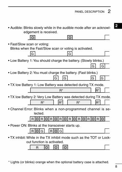
* Lights (or blinks) orange when the optional battery case is attached.
• Audible: Blinks slowly while in the audible mode after an acknowl-edgement is received.
O O
• Fast/Slow scan or voting: Blinks when the Fast/Slow scan or voting is activated.
G G
• Low Battery 1: You should charge the battery. (Slowly blinks.)
G G
• Low Battery 2: You must charge the battery. (Fast blinks.)
G G G G
• TX low Battery 1: Low Battery was detected during TX mode.
R* R*
• TX low Battery 2: Very Low Battery was detected during TX mode.
R* R* R* R*
• Channel Error: Blinks when a non-programmed channel is se-lected.
R O R O R O R O R O R O R O R O
• Power ON: Blinks at the transceiver starts up.
R O G R O G
• TX inhibit: While in the TX inhibit mode such as the TOT or Lock-out function is activated.
R O O O
9
2 PANEL DESCRIPTION
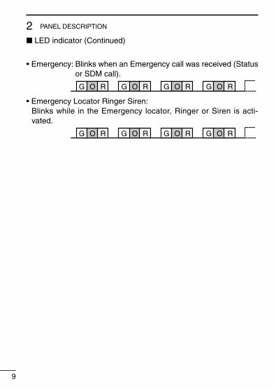
• Emergency: Blinks when an Emergency call was received (Status or SDM call).
G O R G O R G O R G O R
• Emergency Locator Ringer Siren: Blinks while in the Emergency locator, Ringer or Siren is acti-vated.
G O R G O R G O R G O R
■ LED indicator (Continued)
10
2PANEL DESCRIPTION
1
2
3
4
5
6
7
8
9
10
11
12
13
14
15
16
17
18
19
20
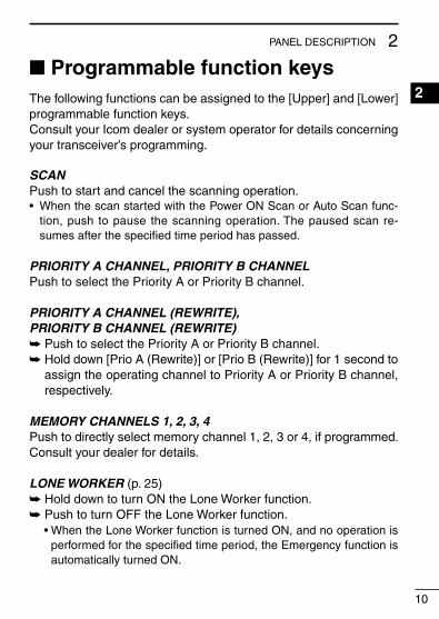
■ Programmable function keysThe following functions can be assigned to the [Upper] and [Lower] programmable function keys.Consult your Icom dealer or system operator for details concerning your transceiver’s programming.
SCANPush to start and cancel the scanning operation.• When the scan started with the Power ON Scan or Auto Scan func-
tion, push to pause the scanning operation. The paused scan re-sumes after the specified time period has passed.
PRIORITY A CHANNEL, PRIORITY B CHANNELPush to select the Priority A or Priority B channel.
PRIORITY A CHANNEL (REWRITE),PRIORITY B CHANNEL (REWRITE)➥ Push to select the Priority A or Priority B channel.➥ Hold down [Prio A (Rewrite)] or [Prio B (Rewrite)] for 1 second to
assign the operating channel to Priority A or Priority B channel, respectively.
MEMORY CHANNELS 1, 2, 3, 4Push to directly select memory channel 1, 2, 3 or 4, if programmed. Consult your dealer for details.
LONE WORKER (p. 25)➥ Hold down to turn ON the Lone Worker function.➥ Push to turn OFF the Lone Worker function. • When the Lone Worker function is turned ON, and no operation is
performed for the specified time period, the Emergency function is automatically turned ON.

11
2 PANEL DESCRIPTION
MONITOR, MONITOR (AUDIBLE)➥ Push to turn the CTCSS (DTCS) or 2/5-tone squelch Mute ON
or OFF. • Only during LMR operation, push to open any squelch func-
tions, or deactivate any mute functions. • Only during PMR operation, push to activate one or two of the
following functions* on each channel. - Hold down to un-mute the channel (Audible mode). - Push to mute the channel (Inaudible mode). - Push to send a ‘reset code’ after the communication is finished. *Ask your dealer for details. NOTE: The un-mute condition may automatically return to
the mute condition, after a specified time period.➥ Depending on the presetting, holding down this key for 1 sec-
ond cancels a scan.
LOCKHold down to electronically lock all programmable keys except [Moni(Audi)], [Call] (including Call A and Call B), [Emergency], Surveillance] and [Lone Worker].
HIGH/LOW (p. 24)Select the transmit output power level temporarily or permanently, depending on the presetting.• Ask your dealer for the output power level for each selection.
TALK AROUND➥ Hold down to turn ON the Talk Around function.➥ Push to turn OFF the Talk Around function. • The Talk Around function equalizes the transmit frequency to the
receive frequency for transceiver-to-transceiver communication.
■ Programmed function keys (Continued)
12
2PANEL DESCRIPTION
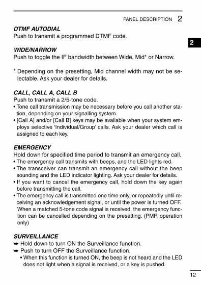
DTMF AUTODIALPush to transmit a programmed DTMF code.
WIDE/NARROWPush to toggle the IF bandwidth between Wide, Mid* or Narrow.
* Depending on the presetting, Mid channel width may not be se-lectable. Ask your dealer for details.
CALL, CALL A, CALL BPush to transmit a 2/5-tone code.• Tone call transmission may be necessary before you call another sta-
tion, depending on your signalling system.• [Call A] and/or [Call B] keys may be available when your system em-
ploys selective ‘Individual/Group’ calls. Ask your dealer which call is assigned to each key.
EMERGENCYHold down for specified time period to transmit an emergency call.• The emergency call transmits with beeps, and the LED lights red.• The transceiver can transmit an emergency call without the beep
sounding and the LED indicator lighting. Ask your dealer for details.• If you want to cancel the emergency call, hold down the key again
before transmitting the call.• The emergency call is transmitted one time only, or repeatedly until re-
ceiving an acknowledgement signal, or until the power is turned OFF. When a matched 5-tone code signal is received, the emergency func-
tion can be cancelled depending on the presetting. (PMR operation only)
SURVEILLANCE➥ Hold down to turn ON the Surveillance function.➥ Push to turn OFF the Surveillance function. • When this function is turned ON, the beep is not heard and the LED
does not light when a signal is received, or a key is pushed.
1
2
3
4
5
6
7
8
9
10
11
12
13
14
15
16
17
18
19
20
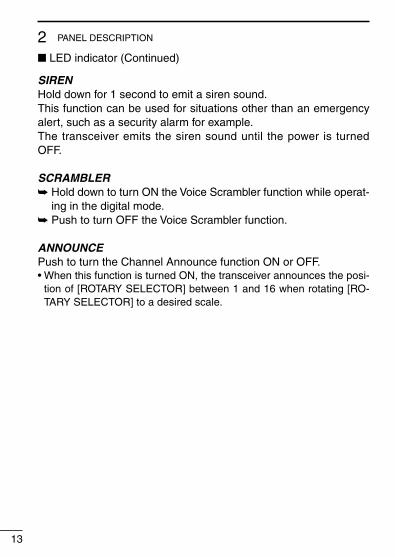
SIRENHold down for 1 second to emit a siren sound.This function can be used for situations other than an emergency alert, such as a security alarm for example.The transceiver emits the siren sound until the power is turned OFF.
SCRAMBLER➥ Hold down to turn ON the Voice Scrambler function while operat-
ing in the digital mode.➥ Push to turn OFF the Voice Scrambler function.
ANNOUNCEPush to turn the Channel Announce function ON or OFF.• When this function is turned ON, the transceiver announces the posi-
tion of [ROTARY SELECTOR] between 1 and 16 when rotating [RO-TARY SELECTOR] to a desired scale.
13
2 PANEL DESCRIPTION
■ LED indicator (Continued)
14
3BASIC OPERATION1
2
3
4
5
6
7
8
9
10
11
12
13
14
15
16
17
18
19
20
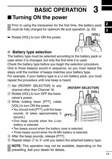
■ Turning ON the powerPrior to using the transceiver for the first time, the battery pack must be fully charged for optimum life and operation. (p. 33)
➥Rotate [VOL] to turn ON the power.
D Battery type selectionThe battery type must be selected according to the battery pack or case when it is changed, but only the first time it is used.Check the battery type before you begin the selection procedure.One to three beep(s) sound in sequence, so you must repeat the steps until the number of beeps matches your battery type.For example, if your battery type is a Li-ion battery pack, you must repeat the procedure until one beep is heard.
q Set [ROTARY SELECTOR] to any channel other than Channel 16.
w Rotate [VOL] to turn OFF the trans-ceiver’s power.
e While holding down [PTT], rotate [VOL] to turn ON the power.
• You should hold [PTT] until the beep sounds. (It takes approximately 5 second.)
• One beep sounds when the Li-ion battery is selected.
• Two beeps sound when the battery case is selected. • Three beeps sound when the Ni-MH battery is selected.r After the beep sounds, release [PTT].t Repeat steps w to r until you select the attached battery type.
NOTE: This operation may not be available, depending on the presetting. Ask your dealer for details.
[VOL]
[VOL]
[PTT]
[ROTARY SELECTOR]

■ Channel selectionSeveral types of channel selections are available. Methods may dif-fer, depending on the presetting.
To select a desired operating channel, do one of the following.• Rotate [ROTARY SELECTOR].• Push one of memory channel keys, [MR-CH 1] to [MR-CH 4].• Push one of these keys, [Prio A], [Prio B], [Prio A (Rewrite)] and
[Prio B (Rewrite)].
AUTOMATIC SCAN TYPE:Selecting a channel is not necessary for this type. When turning ON the power, the transceiver automatically starts scanning. Scanning stops when a signal is detected.
NOTE: If the Move to Priority A channel at Power ON function (p. 24) is turned ON, the transceiver does not start scanning at power ON.
D Voting OperationThe transceiver automatically starts scanning when a zone, speci-fied for the voting operation, is selected.The voting scan detects the signal of the repeater and automati-cally selects the strongest station.
15
3 BASIC OPERATION

16
3BASIC OPERATION
1
2
3
4
5
6
7
8
9
10
11
12
13
14
15
16
17
18
19
20
■ Call procedureWhen your system employs tone signalling (excluding CTCSS and DTCS), the tone call procedure may be necessary prior to voice transmission. The tone signalling that is employed in the transceiver may be a selective calling system, which allows you to call only specific station(s), and prevent unwanted stations from contacting you.
q Select a desired TX code channel or 2/5-tone code, according to your System Operator’s instructions.
• This may not be necessary, depending on programming.w Push [Call] (assigned to one of the dealer programmable keys.)
(p. 12)e After transmitting a 2/5-tone code, the remainder of your com-
munication can be carried out normally.
Selective calling Non-selective calling

17
3 BASIC OPERATION
■ Receiving and transmittingCAUTION: Transmitting without an antenna will damage the transceiver. See page 1 for antenna attachment.
Receiving:q Rotate [VOL] to turn ON the power.w Rotate [ROTARY SELECTOR], or push one of the memory chan-
nel keys, [MR-CH 1] to [MR-CH 4], to select a channel.e When receiving a call, adjust the audio output to a comfortable
listening level.
NOTE: When a matched RX code signal is received, audio from the microphone is automatically transmitted for a specified time period.** Depending on the presetting. Ask your dealer for details.
Transmitting:Wait for the channel to become clear to avoid interference.q While holding down [PTT], speak into the microphone at a nor-
mal voice level.w Release [PTT] to return to receive.
IMPORTANT: To maximize the readability of your signal;1. Pause briefly after pushing [PTT].2. Hold the microphone 5 to 10 cm (2 to 4 inches) from your mouth,
then speak into the microphone at a normal voice level.

18
3BASIC OPERATION
1
2
3
4
5
6
7
8
9
10
11
12
13
14
15
16
17
18
19
20
D Transmitting notes• Transmit inhibit functionThe transceiver has several inhibit functions, which restrict trans-mission under the following conditions:
- The channel is muted. (PMR operation only)- The channel is busy.- A signal with the un-matched (or matched) CTCSS (or DTCS) tone
is received.- The selected channel is a ‘receive only’ channel.
• Time-out timerAfter continuously transmitting longer than the pre-programmed time period, the time-out timer activates, and stops further transmitting.
• Penalty timerOnce the time-out timer activates, transmitting is further inhibited for a time period determined by the penalty timer.
• PTTID callThe transceiver automatically sends the ID code (5-tone, DTMF, BIIS or dPMR operations) when [PTT] is pushed (beginning of the transmission) and/or released (end of transmission), depending on the presetting.

D DTMF transmissionIf the transceiver has [DTMF Autodial] assigned to it, the automatic DTMF transmission function is usable.
➥ Push [DTMF Autodial] to transmit the DTMF code.
D Receiving a Stun, Kill and Revive commandThe dispatcher can send a signal that will stun, kill or revive your transceiver.When the Stun command is received, a beep sounds*, and the transceiver becomes unusable. Receiving a Revive command is necessary to operate the transceiver again in this case.When the Kill command is received, a beep sounds*, and the trans-ceiver becomes unusable (the transceiver switches to the cloning required condition). Cloning the transceiver is necessary to operate the transceiver again in this case.* Depending on the presetting. Ask your dealer for details.
19
3 BASIC OPERATION

■ Setting the microphone gainAdjusts the microphone gain.
q Rotate [VOL] to turn the trans-ceiver power OFF.
w Set [ROTARY SELECTOR] to Channel 16.
e While holding down [Upper], ro-tate [VOL] to turn ON the power and enter the microphone gain adjustment mode.
r Push [Upper] to increase, or push [Lower] to decrease the microphone gain.
• The adjustable range is 1 (mini-mum) to 4 (maximum).
• A beep sounds after pushing [Upper] or [Lower].
An error beep sounds if you try to decrease more than 1 or try to increase more than 4.
Therefore, you can determine the current level setting by the type of beep that sounds.
t Rotate [VOL] to turn the power OFF, then ON again to exit the microphone gain adjustment mode.
NOTE:• This operation may not be available, depending on the preset-
ting. Ask your dealer for details.• When using the VOX function, we recommend setting the mi-
crophone gain to 3. However, you can adjust it to suit your op-erating environment (including your headset performance).
20
3BASIC OPERATION
1
2
3
4
5
6
7
8
9
10
11
12
13
14
15
16
17
18
19
20
[Upper]
[VOL]
[ROTARY SELECTOR]

■ Setting the squelch levelThe squelch circuit mutes the received audio signal, depending on the signal strength.
q Rotate [VOL] to turn the trans-ceiver power OFF.
w Set [ROTARY SELECTOR] to any channel other than Chan-nel 16.
e While holding down [Upper], ro-tate [VOL] to turn ON the power and enter the squelch level ad-justment mode.
r Push [Upper] to increase the squelch level (tight squelch), or push [Lower] to decrease the squelch level (loose squelch).
• The adjustable range is 0 (loose squelch) to 9 (tight squelch).
• A beep sounds after pushing [Upper] or [Lower].
An error beep sounds if you try to decrease more than 0 or try to increase more than 9.
Therefore, you can determine the current level setting by the type of beep that sounds.
t Rotate [VOL] to turn the power OFF, then ON again to exit the squelch level adjustment mode.
NOTE: This operation may not be available, depending on the presetting. Ask your dealer for details.
21
3 BASIC OPERATION
[VOL]
[Upper]
[ROTARY SELECTOR]

■ Setting the Beep levelThe beep function can be turned ON or OFF, and its level can be adjusted between 1 and 5, or 1 (linked) and 5 (linked). When a Linked option is selected, the beep level is adjustable with [VOL].
q Rotate [VOL] to turn the trans-ceiver power OFF.
w Set [ROTARY SELECTOR] to any channel other than Chan-nel 16.
e While holding down [Lower], ro-tate [VOL] to turn ON the power and enter the beep level adjust-ment mode.
r Push [Upper] to change the beep level, or push [Lower] to turn the beep function ON or OFF.
• The adjustable range is 1 to 5 or 1 (Linked) to 5 (Linked).
• If the level is set on 1 to 4 or 1 (Linked) to 4 (Linked), pushing [Upper] increases the level.
If the level is 5 or 5 (Linked), 1 (Linked) or 1 is selected after push-ing [Upper], respectively.
• A beep sounds after pushing [Upper]. Therefore, you can deter-mine the current level setting by the type of beep that sounds.
• One beep sounds when the beep function is turned ON after push-ing [Lower].
t Rotate [VOL] to turn the power OFF, then ON again to exit the beep level adjustment mode.
NOTE: This operation may not be available, depending on the presetting. Ask your dealer for details.
22
3BASIC OPERATION
1
2
3
4
5
6
7
8
9
10
11
12
13
14
15
16
17
18
19
20
[VOL]
[Lower]
[ROTARY SELECTOR]

23
3 BASIC OPERATION
■ Setting the Ringer levelThe Ringer level can be adjusted between 1 and 5, or 1 (Linked) and 5 (Linked). When a Linked option is selected, the Ringer level is adjustable with [VOL].
q Rotate [VOL] to turn the trans-ceiver power OFF.
w Set [ROTARY SELECTOR] to Channel 16.
e While holding down [Lower], ro-tate [VOL] to turn ON the power and enter the Ringer level ad-justment mode.
r Push [Upper] to increase, or push [Lower] to decrease the Ringer level.
• The adjustable range is 1 to 5 or 1 (Linked) to 5 (Linked).
• If the level is set on 5 or 5 (Linked), pushing [Upper] selects 1 (Linked) or 1, respectively. If the level is 1 or 1 (Linked), pushing [Lower] selects 5 (Linked) or 5, respectively.
• A beep sounds after pushing [Upper] or [Lower]. Therefore, you can determine the current level setting by the type of beep that sounds.
t Rotate [VOL] to turn the power OFF, then ON again to exit the beep level adjustment mode.
NOTE: This operation may not be available, depending on the presetting. Ask your dealer for details.
[VOL]
[Lower]
[ROTARY SELECTOR]
24
3BASIC OPERATION
1
2
3
4
5
6
7
8
9
10
11
12
13
14
15
16
17
18
19
20
■ Output power level selectionIf the transceiver has [High/Low] assigned to it, the transmit output power level can be selected, depending on the presetting.When the battery case is selected as the battery type, or the bat-tery voltage drops to a low power level and the LED indicator sta-tus is “Low Battery 2,” the output power automatically switches to “Low 1.” (pp. 8, 14)
➥ Push [High/Low] to select the transmit output power level. • One beep sounds when “Low 1” is selected. • Two beeps sound when “Low 2” is selected. • Three beeps sound when “High” is selected.
■ Priority A channel selectionWhen one of the following operations is performed, the transceiver automatically selects the Priority A channel.
• Turning the power ON The Priority A channel is selected each time the transceiver pow-er is turned ON.
• Auto resetThe Priority A channel is selected when the Auto Reset timer ends.

25
3 BASIC OPERATION
■ Lone Worker Emergency CallWhen the Lone Worker function is turned ON, and no operation is performed for the specified time period*, the transceiver enters the emergency mode, and then the countdown for the emergency call transmission starts.After the specified time period* has passed, an emergency call is automatically transmitted once, or repeatedly*.If someone operates the transceiver before the call is transmitted, the transceiver exits the emergency mode, and the emergency call is can-celled.* Depending on the presetting. Ask your dealer for details.
q Hold down [Lone Worker] to turn ON the Lone Worker function.w Push [Lone Worker] to turn OFF the Lone Worker function.

26
3BASIC OPERATION
1
2
3
4
5
6
7
8
9
10
11
12
13
14
15
16
17
18
19
20
■ Emergency CallWhen [Emergency] is held down for the specified time period*, the emergency signal is transmitted once, or repeatedly, on the speci-fied emergency channel.
A repeat emergency signal is automatically transmitted until you turn the power OFF. Depending on the pre-programmed settings, receiving a matching 5-tone code cancels the transmission. When no emergency channel is specified, the signal is transmitted on the previously selected channel.
If you want to cancel the emergency call, hold down [Emergency] again before transmitting the call.
If your transceiver is programmed for Silent operation, you can transmit an Emergency call without the beep sounding and the LED indicator lighting.
IMPORTANT: It is recommended to set an emergency channel individually to provide the certain emergency call operation.
D NOTESDepending on the presetting, the following functions are automati-cally activated. Ask your dealer for details.
• Auto TX functionAfter the emergency call transmission, audio from the microphone is automatically transmitted for a specified time period.*
• Auto RX functionAfter the emergency call transmission, the transceiver stands by in the audible mode for the specified time period.*
* Depending on the presetting. Ask your dealer for details.

27
4 dPMR OPERATION■ dPMR operationThe transceiver provides digital Private Mobile Radio (dPMR) op-eration that meets the 6.25 kHz bandwidth requirements for narrow band operation. This increases the efficiency of channel allocation and use of the spectrum.
NOTE: During dPMR operation, BIIS 1200 operation is dis-abled.
■ Receiving a callD Receiving an Individual callq When an Individual call is received: • The transceiver will automatically transmit the acknowledge-
ment. • The LED indicator blinks orange. • Beeps sound and the mute is released.w Hold down [PTT], then speak into the microphone.e Release [PTT] to receive a response.r After the communication is finished, push [Clear] to send a ‘Dis-
connect’ signal to terminate the connection.
NOTE: The LED indicator or Beeps may differ, depending on the presetting. Ask your dealer for details.
28
4dPMR OPERATION
1
2
3
4
5
6
7
8
9
10
11
12
13
14
15
16
17
18
19
20
D Receiving a Group callq When a Group call is received: • The LED indicator blinks orange. • Beeps sound and the mute is released.w Hold down [PTT], then speak into the microphone. NOTE: Only one station is allowed to speak at the same
time.e Release [PTT] to receive a response.r After the communication is finished, push [Clear] to send a ‘Dis-
connect’ signal to terminate the connection.
NOTE: The LED indicator or Beeps may differ, depending on the presetting. Ask your dealer for details.
D Receiving a Stun, Kill or ReviveIf an individual call with Stun or Kill command is received, the trans-ceiver will automatically transmit the acknowledgement, and then you cannot receive* or transmit.* Depending on the received Stun command setting.
➥ When a Stun command is received; • The transceiver cannot be operated until the individual call with
Revive command is received or until the data cloning is per-formed.
• Even if [ROTARY SELECTOR] is changed, the transceiver will keep the same channel as the Stun command is received.
➥ When a Kill command is received; • The LED indicator alternately blinks red and green. • The transceiver cannot be operated until the data cloning is
performed. Ask your dealer for details.
NOTE: Depending on the presetting, the transceiver ignores the Stun, Revive and Kill commands, which are from a non-specified station.

29
4 dPMR OPERATION
■ Receiving a call (Continued)
D Receiving a Status Polling callIf a Status Polling call is received, the transceiver will automatically transmit its current status.
D Receiving an Ambience Listening callIf an Individual call with an Ambience Listening command is re-ceived from a specified station, the transceiver will automatically transmit its microphone audio.
NOTE: If the transceiver receives an Ambience Listening com-mand from a station other than the specified one, the call will be ignored, and the transceiver will not transmit its microphone audio.
D Receiving an Emergency call q When an Emergency call is received:
• The transceiver will automatically transmit the acknowledge-ment.
• The LED indicator blinks orange. • Beeps sound and the mute is released.
w Push [Clear] to return to the stand-by mode.
D Talk back functionThe Talk Back function allows you to select the same call mode (Analog or Digital) as the received call.
NOTE: When this function is not activated, the transceiver al-ways transmits analog signals on “Mixed-Analog” channels, and digital signals on “Mixed-Digital” channels. • On these channels, the transceiver can receive both analog
and digital signals, regardless of the Talk Back function.

30
4dPMR OPERATION
1
2
3
4
5
6
7
8
9
10
11
12
13
14
15
16
17
18
19
20
■ Transmitting a calldPMR operation allows you to make a call to a specific station (In-dividual call) or to a particular group (Talkgroup call). Other digital mode transceivers on the channel will not receive a call that does not match their individual or talkgroup ID and/or CC.
D Transmitting a Voice callq Rotate [ROTARY SELECTOR], or push one of the memory chan-
nel keys, [MR-CH 1] to [MR-CH 4], to select a desired channel, Individual ID or Talkgroup ID, depending on the presetting.
w Push [PTT] or [Call] to make a Voice call. • The LED indicator lights red while transmitting. • The LED indicator fast blinks orange. • After an acknowledgement is received, the LED indicator slowly
blinks orange in the audible mode. Or it goes OFF when no acknowledgement is received.
e Hold down [PTT], then speak into the microphone. • The LED indicator lights red while transmitting.r Release [PTT] to receive a response.t After the communication is finished, push [Clear] to send a ‘Dis-
connect’ signal to terminate the connection.

31
4 dPMR OPERATION
■ Transmitting a call (Continued)
D Transmitting an Emergency callWhen [Emergency] is held down for the specified time period, the emergency signal (digital command) is transmitted once or repeat-edly* on the specified emergency channel. When no emergency channel is specified, the signal is transmitted on the operating channel.* When the Repeat Cancel function is ON, the transceiver cancels
repeating after receiving an acknowledgement.When the Repeat Cancel function is OFF, the transceiver repeats calling according to the number of repeat cycles, even after re-ceiving an acknowledgement.
Individual or Talkgroup call types of emergency calls can be pre-fixed. If the call type is not pre-fixed, the default or selected call type is used.
If you want to cancel the emergency call, hold down [Emergency] again before transmitting the call.
If your transceiver is programmed for Silent operation, you can transmit an Emergency call without the beep sounding and the LED indicator lighting.
The transceiver can also be programmed to keep the microphone open during an emergency call, allowing monitoring of the situa-tion.
Ask your dealer for details.
IMPORTANT: It is recommended to set an emergency channel individually to provide the certain emergency call operation.
NOTE: The Digital Request Ack function is activated, the trans-ceiver transmits the emergency call with the request to send back an acknowledgment.
32
4dPMR OPERATION
1
2
3
4
5
6
7
8
9
10
11
12
13
14
15
16
17
18
19
20
■ Position data transmissionWhen an optional HM-171GP or any other GPS receiver is con-nected to the transceiver, the position (longitude and latitude) data can automatically be transmitted when: • When [PTT] is released. - Set the ‘Send with Logoff’ item as ‘Enable.’ • After sending a Status Call. - Set the ‘Send with Status Call’ item as ‘Enable.’ • After sending an SDM. - Set the ‘Send with SDM Call’ item as ‘Enable.’ • After sending an Emergency Call. - Set the ‘Send with Emergency’ item as ‘Enable.’
Ask your dealer or system operator for connection details.
■ Status message transmissionThe status message can automatically be transmitted.The status message is transmitted when the transceiver is turned ON or OFF. - Select a status message to be transmitted in ‘Power ON Status’
or ‘Power OFF Status’ item, respectively. - Select a target station ID in ‘Power Status ID’.
■ Scrambler functionThe voice scrambler function provides private communication be-tween stations while operating in the digital mode.
Hold down [Scrambler] to turn ON the Scrambler function.• Push [Scrambler] to turn OFF the Scrambler function.

33
5 BATTERY CHARGING■ Caution (for the BP-264 ni-mh battery)
R DANGER! KEEP battery packs away from fire. Fire or heat may cause them to rupture or explode. Dispose of an used battery pack in accordance with local regulations.R DANGER! NEVER immerse the battery pack in water. If the bat-tery pack becomes wet, be sure to wipe it dry BEFORE attaching it to the transceiver.R WARNING! NEVER charge the transceiver during a lightning storm. It may result in an electric shock, cause a fire or damage the transceiver. Always disconnect the power adapter before a storm.CAUTION: Always use the battery within the specified temperature range, –5˚C to +55˚C. Using the battery out of its specified temper-ature range will reduce the battery’s performance and battery life.CAUTION: Shorter battery life could occur if the battery is left com-pletely discharged, or in an excessive temperature environment (above +60˚C) for an extended period of time. If the battery must be left unused for a long time, it must be detached from the transceiver after charging. Keep it safely in a cool dry place at the following temperature range: –20˚C to +45˚C (up to a month) –20˚C to +35˚C (up to six months) –20˚C to +25˚C (up to a year*)
* We recommend charging the battery pack every 6 months.Clean the battery terminals to avoid rust or misscontact.Keep the battery terminals clean. It’s a good idea to clean the bat-tery terminals once a week.

34
5BATTERY CHARGING
1
2
3
4
5
6
7
8
9
10
11
12
13
14
15
16
17
18
19
20
If your Ni-MH battery pack seems to have no capacity, even after being charged, completely discharge it by leaving the power ON overnight. Then, fully charge the battery pack again. If the battery pack still does not retain a charge (or only very little charge), a new battery pack must be purchased. (p. 45)Prior to using the transceiver for the first time, the battery pack must be fully charged for optimum life and operation.• Recommended temperature range for charging:
between +10°C and +40°C (rapid charge: with BC-191) or between 0°C and +45°C (regular charge: with BC-192)
• Use the supplied charger or optional charger (BC-191 for rapid charging, BC-192 for regular charging) only. NEVER use other manufacturers’ chargers.
The battery pack contains a rechargable battery.Charge the battery pack before first operating the transceiver, or when the battery pack becomes exhausted.If you want to prolong the battery life, the following points should be observed:• Avoid over charging. The charging time period by the BC-192
should be less than 48 hours.• Use the battery pack until it becomes almost completely ex-
hausted, under normal conditions. We recommend battery charg-ing after transmitting becomes impossible.

■ Caution (for the BP-265 Li-ion battery)
Misuse of Li-ion batteries may result in the following hazards: smoke, fire, or the battery may rupture. Misuse can also cause damage to the battery or degradation of battery performance.
D Battery cautionR DANGER! DO NOT hammer or otherwise impact the battery. Do not use the battery if it has been severely impacted or dropped, or if the battery has been subjected to heavy pressure. Battery damage may not be visible on the outside of the case. Even if the surface of the battery does not show cracks or any other damage, the cells inside the battery may rupture or catch fire.
R DANGER! NEVER use or leave battery packs in areas with temperatures above +60˚C. High temperature buildup in the bat-tery, such as could occur near fires or stoves, inside a sun-heated vehicle, or in direct sunlight for long periods of time may cause the battery to rupture or catch fire. Excessive temperatures may also degrade battery performance or shorten battery life.
R DANGER! DO NOT expose the battery to rain, snow, seawater, or any other liquids. Do not charge or use a wet battery. If the bat-tery gets wet, be sure to wipe it dry before using. The battery is not waterproof.
R DANGER! KEEP battery packs away from fire. Fire or heat may cause them to rupture or explode. Dispose of an used battery pack in accordance with local regulations.
R DANGER! NEVER solder the battery terminals or NEVER mod-ify the battery pack. This may generate heat in the battery, and the battery pack may burst, emit smoke or catch fire.
35
5 BATTERY CHARGING

36
5BATTERY CHARGING
1
2
3
4
5
6
7
8
9
10
11
12
13
14
15
16
17
18
19
20
R DANGER! Use the battery only with the transceiver for which it is specified. Never use a battery with any other equipment, or for any purpose that is not specified in this instruction manual.
R DANGER! If fluid from inside the battery gets in your eyes, blind-ness can result. Rinse your eyes with clean water, without rubbing them, and see a doctor immediately.
R WARNING! Immediately stop using the battery if it emits an ab-normal odor, heats up, or is discolored or deformed. If any of these conditions occur, contact your Icom dealer or distributor.
R WARNING! Immediately wash, using clean water, any part of the body that comes into contact with fluid from inside the battery.
R WARNING! NEVER put the battery in a microwave oven, high-pressure container, or in an induction heating cooker. This could cause a fire, overheating, or cause the battery to rupture.
CAUTION: Always use the battery within the specified temperature range, –20˚C to +55˚C. Using the battery out of its specified tem-perature range will reduce the battery’s performance and battery life.
CAUTION: Shorter battery life could occur if the battery is left fully charged, completely discharged, or in an excessive temperature environment (above +50˚C) for an extended period of time. If the battery must be left unused for a long time, it must be detached from the transceiver after discharging. You may use the battery until the remaining capacity is about half, then keep it safely in a cool dry place within the temperature range as shown below: –20˚C to +50˚C (up to a month) –20˚C to +35˚C (up to three months) –20˚C to +20˚C (up to a year)

37
5 BATTERY CHARGING
BE SURE to replace the battery pack with a new one approxi-mately five years after manufacturing, even if it still holds a charge. The inside battery material will become weak after a period of time, even with little use. The estimated number of times you can charge the battery is between 300 and 500.Even when the battery appears to be fully charged, the operating time of the transceiver may become short when:• Approximately five years have passed since the battery was man-
ufactured.• The battery has been repeatedly charged.
D Charging cautionR DANGER! NEVER charge the battery pack in areas with ex-tremely high temperatures, such as near fires or stoves, inside a sun heated car, or in direct sunlight. In such environments, the safety/protection circuit in the battery will activate, causing the bat-tery to stop charging.R WARNING! NEVER charge the transceiver during a lightning storm. It may result in an electric shock, cause a fire or damage the transceiver. Always disconnect the power adapter before a storm.
R WARNING! DO NOT charge or leave the battery in the battery charger beyond the specified time for charging. If the battery is not completely charged by the specified time, stop charging and re-move the battery from the battery charger. Continuing to charge the battery beyond the specified time limit may cause a fire, overheat-ing, or the battery may rupture.
R WARNING! NEVER insert the transceiver (battery attached to the transceiver) into the charger if it is wet or soiled. This could corrode the battery charger terminals or damage the charger. The charger is not waterproof.
CAUTION: DO NOT charge the battery outside of the specified temperature range: BC-193 (+10˚C to +40˚C). Icom recommends charging the battery at +20˚C. The battery may heat up or rupture if charged out of the specified temperature range. Additionally, bat-tery performance or battery life may be reduced.

38
5BATTERY CHARGING
1
2
3
4
5
6
7
8
9
10
11
12
13
14
15
16
17
18
19
20
■ Battery chargersD Using the BC-191 to rapid charge the BP-264The BC-191 provides rapid charging of the Ni-MH battery pack (BP-264 only). Never use for any other battery pack.Charging time period: Approximately 2 hours (for the BP-264)
The following item is additionally required:• A power adapter (not supplied with some versions) or the DC
power cable (OPC-515L/CP-23L).
Status indicator• Lights orange: While charging.• Lights green: Charging is completed.
Power adapter(A different type, or no power adapter is sup-plied, depending on the version.)
About OPC-515LWhite line:Black line :
CAUTION: NEVER connect the OPC-515L to a power source using reverse polarity. This will ruin the battery charger.
*
Battery pack Transceiver
Turn OFF the power
Optional OPC-515L* (for power source) or CP-23L (for 12 V cig-arette lighter socket) can be used instead of the power adapter.
Screws*( Self tapping screw: M3.5 × at least 30 mm)
*Purchase separately. Using screws is recom-mended to secure the charger.
39
5 BATTERY CHARGING
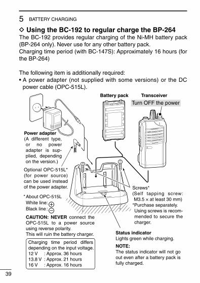
D Using the BC-192 to regular charge the BP-264The BC-192 provides regular charging of the Ni-MH battery pack (BP-264 only). Never use for any other battery pack.Charging time period (with BC-147S): Approximately 16 hours (for the BP-264)
The following item is additionally required:• A power adapter (not supplied with some versions) or the DC
power cable (OPC-515L).
Power adapter(A different type, or no power adapter is sup-plied, depending on the version.)
Charging time period differs depending on the input voltage.12 V13.8 V16 V
: Approx. 36 hours: Approx. 21 hours: Approx. 16 hours
About OPC-515LWhite line:Black line :
CAUTION: NEVER connect the OPC-515L to a power source using reverse polarity. This will ruin the battery charger.
*
Battery pack Transceiver
Turn OFF the power
Optional OPC-515L* (for power source) can be used instead of the power adapter. Screws*
( Self tapping screw: M3.5 × at least 30 mm)
*Purchase separately. Using screws is recom-mended to secure the charger.
Status indicatorLights green while charging.
NOTE:The status indicator will not go out even after a battery pack is fully charged.
40
5BATTERY CHARGING
1
2
3
4
5
6
7
8
9
10
11
12
13
14
15
16
17
18
19
20
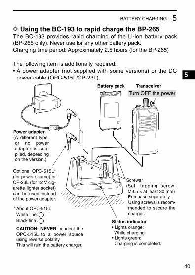
D Using the BC-193 to rapid charge the BP-265The BC-193 provides rapid charging of the Li-ion battery pack (BP-265 only). Never use for any other battery pack.Charging time period: Approximately 2.5 hours (for the BP-265)
The following item is additionally required:• A power adapter (not supplied with some versions) or the DC
power cable (OPC-515L/CP-23L).
Status indicator• Lights orange: While charging.• Lights green: Charging is completed.
Power adapter(A different type, or no power adapter is sup-plied, depending on the version.)
About OPC-515LWhite line:Black line :
CAUTION: NEVER connect the OPC-515L to a power source using reverse polarity. This will ruin the battery charger.
*
Battery pack Transceiver
Turn OFF the power
Optional OPC-515L* (for power source) or CP-23L (for 12 V cig-arette lighter socket) can be used instead of the power adapter.
Screws*( Self tapping screw: M3.5 × at least 30 mm)
*Purchase separately. Using screws is recom-mended to secure the charger.
41
5 BATTERY CHARGING
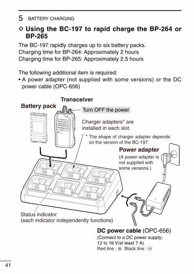
D Using the BC-197 to rapid charge the BP-264 or BP-265
The BC-197 rapidly charges up to six battery packs.Charging time for BP-264: Approximately 2 hoursCharging time for BP-265: Approximately 2.5 hours
The following additional item is required:• A power adapter (not supplied with some versions) or the DC
power cable (OPC-656)
(A power adapter isnot supplied withsome versions.)
Power adapter
(Connect to a DC power supply; 12 to 16 V/at least 7 A)Red line : + Black line : _
TransceiverBattery pack
Turn OFF the power
Status indicator(each indicator independently functions)
Charger adapters* areinstalled in each slot.
The shape of charger adapter depends on the version of the BC-197.
*
DC power cable (OPC-656)
42
5BATTERY CHARGING
1
2
3
4
5
6
7
8
9
10
11
12
13
14
15
16
17
18
19
20
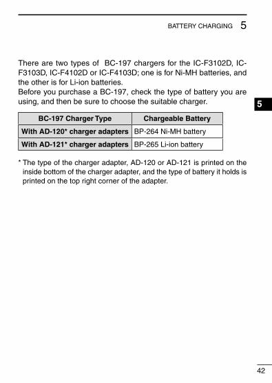
There are two types of BC-197 chargers for the IC-F3102D, IC-F3103D, IC-F4102D or IC-F4103D; one is for Ni-MH batteries, and the other is for Li-ion batteries.Before you purchase a BC-197, check the type of battery you are using, and then be sure to choose the suitable charger.
BC-197 Charger Type Chargeable Battery
With AD-120* charger adapters BP-264 Ni-MH battery
With AD-121* charger adapters BP-265 Li-ion battery
* The type of the charger adapter, AD-120 or AD-121 is printed on the inside bottom of the charger adapter, and the type of battery it holds is printed on the top right corner of the adapter.

43
5 BATTERY CHARGING
IMPORTANT: Ensure the tabs on the battery pack are correctly aligned with the guide rails inside the charger.
Guide rail
Tabs
BC-191, BC-192, BC-193
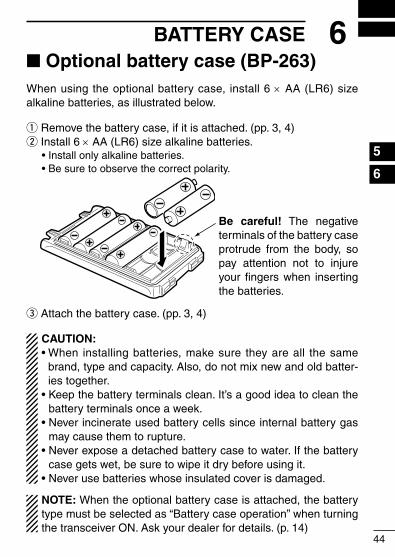
■ Optional battery case (BP-263)When using the optional battery case, install 6 × AA (LR6) size alkaline batteries, as illustrated below.
q Remove the battery case, if it is attached. (pp. 3, 4)w Install 6 × AA (LR6) size alkaline batteries. • Install only alkaline batteries. • Be sure to observe the correct polarity.
e Attach the battery case. (pp. 3, 4)
CAUTION:• When installing batteries, make sure they are all the same
brand, type and capacity. Also, do not mix new and old batter-ies together.
• Keep the battery terminals clean. It’s a good idea to clean the battery terminals once a week.
• Never incinerate used battery cells since internal battery gas may cause them to rupture.
• Never expose a detached battery case to water. If the battery case gets wet, be sure to wipe it dry before using it.
• Never use batteries whose insulated cover is damaged.
NOTE: When the optional battery case is attached, the battery type must be selected as “Battery case operation” when turning the transceiver ON. Ask your dealer for details. (p. 14)
44
6BATTERY CASE1
2
3
4
5
6
7
8
9
10
11
12
13
14
15
16
17
18
19
20
Be careful! The negative terminals of the battery case protrude from the body, so pay attention not to injure your fingers when inserting the batteries.
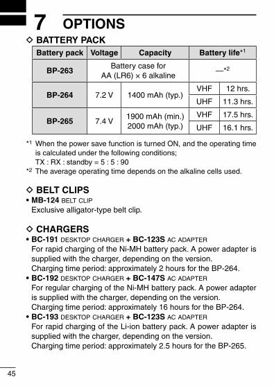
D BATTERY PACKBattery pack Voltage Capacity Battery life*1
BP-263Battery case for
AA (LR6) × 6 alkaline—*2
BP-264 7.2 V 1400 mAh (typ.)VHF 12 hrs.
UHF 11.3 hrs.
BP-265 7.4 V1900 mAh (min.)2000 mAh (typ.)
VHF 17.5 hrs.
UHF 16.1 hrs.
*1 When the power save function is turned ON, and the operating time is calculated under the following conditions;
TX : RX : standby = 5 : 5 : 90*2 The average operating time depends on the alkaline cells used.
D BELT CLIPS• MB-124 beLt cLip
Exclusive alligator-type belt clip.
D CHARGERS• BC-191 desktop charger + BC-123S ac adapter
For rapid charging of the Ni-MH battery pack. A power adapter is supplied with the charger, depending on the version.
Charging time period: approximately 2 hours for the BP-264.• BC-192 desktop charger + BC-147S ac adapter
For regular charging of the Ni-MH battery pack. A power adapter is supplied with the charger, depending on the version.
Charging time period: approximately 16 hours for the BP-264.• BC-193 desktop charger + BC-123S ac adapter
For rapid charging of the Li-ion battery pack. A power adapter is supplied with the charger, depending on the version.
Charging time period: approximately 2.5 hours for the BP-265.
45
7 OPTIONS
46
7OPTIONS
1
2
3
4
5
6
7
8
9
10
11
12
13
14
15
16
17
18
19
20
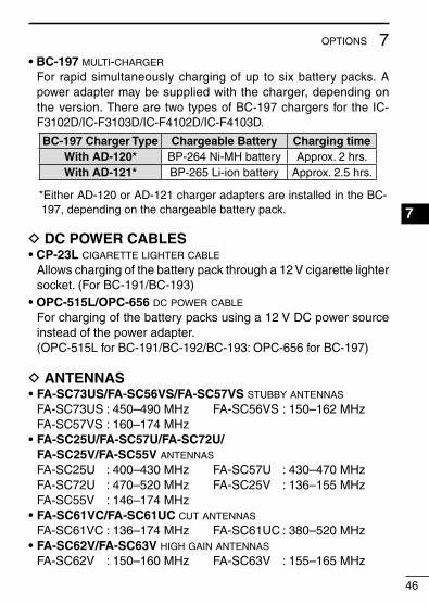
• BC-197 muLti-charger
For rapid simultaneously charging of up to six battery packs. A power adapter may be supplied with the charger, depending on the version. There are two types of BC-197 chargers for the IC-F3102D/IC-F3103D/IC-F4102D/IC-F4103D.
BC-197 Charger Type Chargeable Battery Charging timeWith AD-120* BP-264 Ni-MH battery Approx. 2 hrs.With AD-121* BP-265 Li-ion battery Approx. 2.5 hrs.
* Either AD-120 or AD-121 charger adapters are installed in the BC-197, depending on the chargeable battery pack.
D DC POWER CABLES• CP-23L cigarette Lighter cabLe
Allows charging of the battery pack through a 12 V cigarette lighter socket. (For BC-191/BC-193)
• OPC-515L/OPC-656 dc power cabLe
For charging of the battery packs using a 12 V DC power source instead of the power adapter.
(OPC-515L for BC-191/BC-192/BC-193: OPC-656 for BC-197)
D ANTENNAS• FA-SC73US/FA-SC56VS/FA-SC57VS stubby antennas
FA-SC73US : 450–490 MHz FA-SC56VS : 150–162 MHz FA-SC57VS : 160–174 MHz• FA-SC25U/FA-SC57U/FA-SC72U/
FA-SC25V/FA-SC55V antennas
FA-SC25U : 400–430 MHz FA-SC57U : 430–470 MHz FA-SC72U : 470–520 MHz FA-SC25V : 136–155 MHz FA-SC55V : 146–174 MHz• FA-SC61VC/FA-SC61UC cut antennas
FA-SC61VC : 136–174 MHz FA-SC61UC : 380–520 MHz• FA-SC62V/FA-SC63V high gain antennas
FA-SC62V : 150–160 MHz FA-SC63V : 155–165 MHz
47
7 OPTIONS
D OTHER OPTIONS• AD-98FSC antenna connector converter
Allows you to connect an external antenna with a BNC connector.• HM-158L/HM-159L speaker-microphone
Combination speaker-microphone that provides convenient op-eration while hanging the transceiver on your belt.
• HM-171GP speaker-microphone
GPS speaker-microphone for BIIS and Digital modes operation.• HS-94/HS-95/HS-97 headset + OPC-2004 pLug adapter cabLe
HS-94 : Ear hook type HS-95 : Neck-arm type HS-97 : Throat microphone OPC-2004 : Allows you to connect the HS-94/HS-95/HS-97 to the
transceiver. After connection, the VOX function can be used.
• SP-27 tube earphone
Provides clear audio in noisy environments.
Some options may not be available in some countries. Please ask your dealer for details.
48
7OPTIONS
1
2
3
4
5
6
7
8
9
10
11
12
13
14
15
16
17
18
19
20
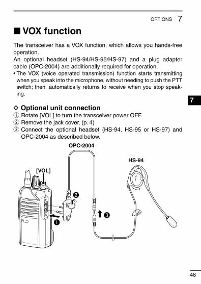
■ VOX functionThe transceiver has a VOX function, which allows you hands-free operation.An optional headset (HS-94/HS-95/HS-97) and a plug adapter cable (OPC-2004) are additionally required for operation.• The VOX (voice operated transmission) function starts transmitting
when you speak into the microphone, without needing to push the PTT switch; then, automatically returns to receive when you stop speak-ing.
D Optional unit connectionq Rotate [VOL] to turn the transceiver power OFF.w Remove the jack cover. (p. 4)e Connect the optional headset (HS-94, HS-95 or HS-97) and
OPC-2004 as described below.
HS-94
OPC-2004
q
w
e
[VOL]

49
7 OPTIONS
D Turning the VOX function ON or OFFThe VOX function can be turned ON or OFF when turning the trans-ceiver power ON.
q Rotate [VOL] to turn the trans-ceiver power OFF.
w Set [ROTARY SELECTOR] to any channel other than Chan-nel 16.
e While holding down [PTT] and [Upper], rotate [VOL] to turn ON the power to switch the VOX function ON or OFF.
• One beep sounds when the VOX function is turned OFF.
• Two beeps sound when the VOX function is turned ON.
NOTE: This operation may not be available, depending on the presetting. Ask your dealer for details.
[VOL]
[Upper]
[PTT]
[ROTARY SELECTOR]
50
7OPTIONS
1
2
3
4
5
6
7
8
9
10
11
12
13
14
15
16
17
18
19
20
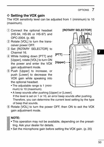
D Setting the VOX gainThe VOX sensitivity level can be adjusted from 1 (minimum) to 10 (maximum).
q Connect the optional headset (HS-94, HS-95 or HS-97) and OPC-2004. (p. 48)
w Rotate [VOL] to turn the trans-ceiver power OFF.
e Set [ROTARY SELECTOR] to Channel 16.
r While holding down [PTT] and [Upper], rotate [VOL] to turn ON the power and enter the VOX gain adjustment mode.
t Push [Upper] to increase, or push [Lower] to decrease the VOX gain while speaking into the optional headset.
• The adjustable range is 1 (mini-mum) to 10 (maximum).
• A beep sounds after pushing [Upper] or [Lower]. If the level is set on 1 or 10, an error beep sounds after pushing. Therefore, you can determine the current level setting by the type
of beep that sounds.y Rotate [VOL] to turn the power OFF, then ON to exit the VOX
gain adjustment mode.
NOTE:• This operation may not be available, depending on the preset-
ting. Ask your dealer for details.• Set the microphone gain before setting the VOX gain. (p. 20)
[VOL]
[Upper]
[PTT]
[ROTARY SELECTOR]

51
8 INFORMATION
■ Country code list• ISO 3166-1
Country Codes Country Codes
1234567891011121314151617
AustriaBelgiumBulgariaCroatiaCzech RepublicCyprusDenmarkEstoniaFinlandFranceGermanyGreeceHungaryIcelandIrelandItalyLatvia
ATBEBGHRCZCYDKEEFIFRDEGRHUISIEITLV
18192021222324252627282930313233
LiechtensteinLithuaniaLuxembourgMaltaNetherlandsNorwayPolandPortugalRomaniaSlovakiaSloveniaSpainSwedenSwitzerlandTurkeyUnited Kingdom
LILTLUMTNLNOPLPTROSKSIESSECHTRGB
52
8INFORMATION
1
2
3
4
5
6
7
8
9
10
11
12
13
14
15
16
17
18
19
20
■ DisposalThe crossed-out wheeled-bin symbol on your product, lit-erature, or packaging reminds you that in the European Union, all electrical and electronic products, batteries, and accumulators (rechargeable batteries) must be taken to
designated collection locations at the end of their working life. Do not dispose of these products as unsorted municipal waste. Dis-pose of them according to the laws in your area.

1-1-32 Kamiminami, Hirano-ku, Osaka 547-0003, Japan
< Intended Country of Use >ATFIITPLGBRO
BEFRLVPTISTR
CYDELTSKLIHR
CZGRLUSINO
DKHUMTESCH
EEIENLSEBG
A-7061D-1EU-wPrinted in Japan© 2012–2016 Icom Inc.
Printed on recycled paper with soy ink.