identifyingandunderstanding performance ...contents!! tableofcontents 2!...
TRANSCRIPT

Identifying and understanding performance bottlenecks with Aspera
Transfers
Aspera Technical Services Dept. May, 2012

Table of Contents Table of Contents....................................................................................................................................... 2 Performance bottlenecks due to Aspera license or bandwidth settings........................... 3 Aspera License Cap .............................................................................................................................. 3 Aspera Target Rate .............................................................................................................................. 3 Aspera Virtual Link.............................................................................................................................. 3 Other: Connect Client......................................................................................................................... 3
Most comm r................................................................................................................................................ 4 Performance bottlenecks due to systems and storage.............................................................. 4 I/O Sender or receiver NAS / SAN ................................................................................................ 4 Sender or Receiver CPU ..................................................................................................................... 4 Sender or receiver Network Card.................................................................................................. 5
Performance bottlenecks due to networks and network devices........................................ 5 Sender or receiver VPN/ Router.................................................................................................... 5 Sender or receiver Firewall / QOS ................................................................................................ 5
Appendix A ................................................................................................................................................... 6 How to identify the limitation......................................................................................................... 6 Aspera license cap ........................................................................................................................... 6 Aspera server target rate ............................................................................................................. 7 Aspera client target rate .............................................................................................................10 Virtual Link setting .......................................................................................................................12
Senders Disk .........................................................................................................................................17 Firewall ...................................................................................................................................................18 VPN / Router ........................................................................................................................................19

Performance bottlenecks due to Aspera license or bandwidth settings
Figure 1: Aspera configuration and license bottlenecks
Aspera License Cap All Licensed Aspera Clients and Servers have a bandwidth capacity limit. You can check the license cap via the command line or GUI.
Aspera Target Rate Aspera Clients always request a target rate. Aspera servers will either allow the client to transfer at the rate requested, or will throttle the client to a rate which is set by the server.
Aspera Virtual Link Aspera clients and servers are capable of restricting the maximum aggregate transfer rate. This feature is called Virtual Link. The client virtual link is set via the Graphical User Interface, in the Preferences section.
Other: Connect Client
Most common performance bottlenecks
Figure 2: Most common performance bottlenecks

Physical Bandwidth at Sender or Receiver Available physical bandwidth is the most common limitation on transfer performance. The bandwidth at the sender and receiver is often different, as shown in the diagram above.
I/O Receiver or Sender Disk The receiver disk limits transfer speed more often than the sender disk. The I/O limitation is more common with high concurrency or high packet loss. I/O bottlenecks can be hard to detect, if the disk is occasionally accessed by other applications, for example, NFS or CIFS shares.
CPU Sender or receiver The CPU can be a bottleneck, especially when using encryption for high speed transfers. Currently the ascp process is not multithreaded, so if you have multiple concurrent transfers, it is important to have multiple CPU or multi core system, so you can spread the CPU load.
Performance bottlenecks due to systems and storage
I/O Sender or receiver NAS / SAN Using remote storage can be a bottleneck for high speed transfers. Sometimes this is due to the storage (physical configuration, disks), and sometimes this can be due to the network file system (NFS or CIFS).
Sender or Receiver CPU or Memory The CPU or memory can be a bottleneck, especially when using encryption for high speed transfers. Currently the ascp process is not multithreaded, so if you have multiple concurrent transfers, it is important to have multiple CPU or multi core system, so you can spread the CPU load. When doing high speed transfers or highly concurrent transfers it is possible to run into a memory bottleneck.

Sender or receiver Network Card Although unusual, it is possible that a network card has a physical limit, or the network card driver configuration is creating a limit. On a few occasions, we have observed that buggy network card drivers cause transfer performance issues.
Performance bottlenecks due to networks and network devices
Sender or receiver VPN/ Router VPN can reduce performance of Aspera FASP transfers. This can happen when the VPN device is fragmenting packets and Aspera is unable to detect that the packets were being fragmented.
Sender or receiver Firewall / QOS Firewalls that implement QOS (Quality of Service) or other bandwidth restrictions can be the cause of performance limitations. Firewalls that perform deep packet inspection (IDS/IPS) can cause transfers to slow down.
Sender or receiver WAN link ISPs may limit UDP throughput or completely block UDP after some fixed period of time.
Appendix A
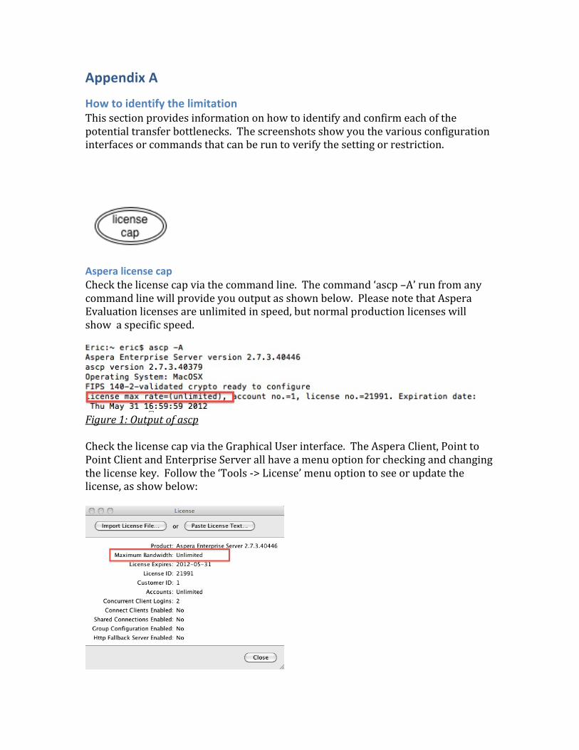
How to identify the limitation This section provides information on how to identify and confirm each of the potential transfer bottlenecks. The screenshots show you the various configuration interfaces or commands that can be run to verify the setting or restriction.
Aspera license cap Check the license cap via the command line. The command ‘ascp –A’ run from any command line will provide you output as shown below. Please note that Aspera Evaluation licenses are unlimited in speed, but normal production licenses will show a specific speed.
Figure 1: Output of ascp Check the license cap via the Graphical User interface. The Aspera Client, Point to Point Client and Enterprise Server all have a menu option for checking and changing the license key. Follow the ‘Tools -‐> License’ menu option to see or update the license, as show below:

Figure 2: License configuration dialogue
Aspera server target rate Check the Aspera Target rate on the server via the server configuration panel. In the screenshot below, you can see the configuration for the user ‘eric’ where the bandwidth Incoming Target Rate Cap is set to ’20,000 Kbps’ (20 Mbps).
Figure 3: Server configuration for user ‘eric’ If you are on a Linux or Unix system, you can always review the configuration in aspera.conf directly. The aspera.conf file contains all settings for Aspera users. In the screenshot below, you can see the user section of aspera.conf where the user eric has a target rate set at 20,000 Kbps for inbound and for outbound tranfsers.

Figure 4: Example section of aspera.conf It is also possible to query the configuration file directly using asuserdata which is a command utility provided with our products for validating and checking a configuration file. The basic syntax of this utility, for checking the user eric is ‘asuserdata –u eric’. The command can be found in the same location as the ascp file. They are both located in the bin sub directory of the Aspera install. The screenshot below, shows a portion of the output from the command ‘asuserdata –u eric’.

Figure 5: Example output of asuserdata The Aspera Management Console can be used to view and configure the target rate configurations. The screen shots below show the Configuration interface for default system target rate as well as the user target rate setting.

Figure 6: Console system default configuration
Figure 7: Console Account Bandwidth configuration
Aspera client target rate The Aspera Client, Point to Point Client and Enterprise Server endpoint configuration allows you to set the default target rate for the endpoint.

Figure 8: Graphical user interface endpoint configuration The target rate can also be set when initiating a transfer. This dialogue below shows the interface for setting a target rate upon transfer initiation. This setting will override the default end point target rate setting.
Figure 9: Graphical user interface – per transfer target rate setting The Connect browser plug-‐in preferences panel has a Maximum allowed connection speed. If this setting is lower than the available bandwidth, or network capacity, it can artificially limit the transfer speed. The default for this setting is 45 Mbps. In the screen shot below you can see the speed is set to 200 Mbps.

Figure 10: Browser plug-in network preferences setting
Client virtual link setting The Aspera Client, Point to Point Client and Enterprise Server graphical user interface provides a client configuration via the Preferences configuration dialogue. In the screen shot below, you can see the client has set a maximum allowed aggregate rate of 100 Mbps.

Figure 11: Client preference setting for Global Bandwidth Limit
Server virtual link setting The Server configuration panel in the Point to Piont and Enterprise Server products allows you to set and view the Virutal link policy as a default, per group or per user. The first screen shot below shows a virtual link configured for 100Mbps (100000 Kbps). The second screen shot below shows that the virtual link ID 101 has been applied to the aspera user for incoming transfers.
Figure 12: Server Configuration for Virtual Link

Figure 13: Server Configuration – users Virtual link setting If you are on a unix or Linux system, you may need to view the configuration file (aspera.conf) to see what virtual link policy is applied as a system default, or for groups or users. The first screen shot below shows a default configuration for all users (the <default> section applies to all users). The second screen shot shows the Vlink policy applied to the aspera user.
Figure 14: Aspera.conf – default Virtual link setting for all users

Figure 15: Aspera.conf – Virtual link setting for user aspera If the configuration file is too large and difficult to read, you can also query the configuration file using the utility ‘asuserdata’. This utility will aggregate the configuration file settings for default, group and users and output the specific settings for the specified user.

Figure 16: asuserdata – Virtual link setting for user aspera

Network bandwidth ISP – rate limiting, or UDP blocking. How long does transfer last? View details of Transfer session.
Senders / Receiver Disk In higher speed or high concurrent transfers, I/O limitations can become a bottleneck. There are a few methods for determining your storage I/O capabilities. One such method is a set of Aspera transfer options (-‐-‐no-‐read –no-‐write), which allow you to eliminate either the reading from or writing to disk, as part of a transfer. This will show your network capacity, independent of your storage throughput. The Aspera Support portal provides an excellent article on testing I/O performance: https://support.asperasoft.com/entries/20999488-‐performance-‐testing There are also third party tools. One we recommend is the open souce IOzone tool kit which is freely downloadable from the internet. (IOzone.org). Please review the Aspera Knowledgebase for detailed examples on how to test using IOzone.

Senders / Receiver SAN or NAS storage Generally with SAN devices, if you have I/O performance issues, there is a configuration issue with the SAN. Please work with you storage team or SAN vendor to review the configuration. With NAS devices, performance problems can be more complicated to debug. Please review this Support KB article for more details, or contact Aspera Support: https://support.asperasoft.com/entries/20151793-‐improving-‐nfs-‐performance-‐on-‐the-‐lan Other testing options: Run IOzone against these devices – it will tell you the optimum block size and maximum expected speed. For CIFS, be sure to use SMB2. For NFS – use kernel parameters, and also Aspera block size writes / reads.
Firewall Rate limiting and deep packet inspection can be hard to verify without direct access to the firewall configuration. If your organization has a security team, we would recommend that you contact them to review the firewall configuration. One indicator of rate limiting is a high packet loss rate. The best way to validate this is to run the following test with the full desktop client. You can also use the GUI on our server products to run this test. Start a transfer to the server, using an Aspera client, using a low target rate at FIXED mode (e.g. 5 Mbps). Open up the detail view of this transfer session, and confirm that you have no packet loss. Gradually increase the target rate, and observe both the transfer rate and packet loss. At some speed (usually a fixed amount) the actual transfer rate will not increase any more, but the packet loss will. The first screenshot below show the initial transfer at a low speed without packet loss. The second screenshot shows a higher target rate transfer where the actual rate is less than the target rate, but the packet loss is quite high.

VPN / Router It is possible to have a CPU limitation on the VPN/Router device. The aspera transfer will be slower than the target rate. In most cases, there will be no or minimal packet loss but an increase in delay (RTT). In some cases, this will result in higher loss. This situation is exacerbated when the VPN devices are configured to defeat path MTU discovery, and the data packets are fragmented by the VPN device. Aspera uses path MTU discovery at the beginning of a transfer session to determine the appropriate packet size. If this process is defeated, then Aspera will send packets at the standard size (1492 bytes). Both Cisco and Juniper VPN devices can be configured to defeat path MTU discovery by clearing the DF bit (do not fragment).