iec 61850 – what it can and cannot offer to traditional protection
TRANSCRIPT

IEC 61850 – What It Can and Cannot Offer to Traditional Protection Schemes
Daqing Hou and Dave Dolezilek Schweitzer Engineering Laboratories, Inc.
Published in SEL Journal of Reliable Power, Volume 1, Number 2, October 2010
Previously presented at the 1st Annual Protection, Automation and Control World Conference, June 2010
Originally published in the proceedings of the 35th Annual Western Protective
Relay Conference as an alternate, October 2008

1
IEC 61850 – What It Can and Cannot Offer to Traditional Protection Schemes
Daqing Hou and Dave Dolezilek, Schweitzer Engineering Laboratories, Inc.
Abstract—As the latest standard that is quickly gaining popularity in power substation automation, IEC 61850 offers self-descriptive object data models, standardized configurability with Substation Configuration Language (SCL), the promise of interoperations among intelligent electronic devices (IEDs) from different manufacturers, and lower integration installation costs. The IEC 61850 standard initially focused on communications between IEDs within a single power substation. However, the working groups of IEC Technical Committee TC57 are prepar-ing IEC 61850 for communications between substations and between substations and control centers. Most existing papers regarding IEC 61850 concentrate on the standard, communica-tion, and automation.
In this paper, from a protection engineer’s point of view, we examine what the standard can and cannot offer to traditional protection schemes that require communications assistance. These protection schemes include fast bus tripping, breaker failure, directional comparison blocking (DCB), permissive overreaching transfer trip (POTT), and others. We review the Generic Object-Oriented Substation Event (GOOSE) control mode mechanism of the standard: its generation, mapping, com-munication over local-area and wide-area networks, and timing aspects. With this knowledge, we compare the use of GOOSE messages with traditional protection schemes in terms of feasibility, speed, and dependability.
I. INTRODUCTION Modern microprocessor relays are no longer merely
protection devices for power apparatus but have evolved to perform many other functions that facilitate effective power system operation. Contemporary microprocessor relays routinely include metering, protection, automation, control, digital fault recording (DFR), and reporting. Because of this, it is now more accurate to refer to these microprocessor devices as intelligent electronic devices (IEDs). As IEDs replace old electromechanical relays and prevail in today’s power substations, the amount of data available from substations increases exponentially.
Early supervisory control and data acquisition (SCADA) systems integrated information from generation stations and substations through remote terminal units (RTUs) to provide operators with system-wide knowledge to plan and operate the power system. These RTUs and SCADA systems typically used additional transducers and contacts that were separate from the protection systems to acquire system information. The information update was also slow for these systems, on the order of several seconds to minutes. Now the substation’s IEDs are performing more system automation and control functions. Almost all the information required by system operators (and more) is available from these IEDs once they are networked together. These substation IED networks reduce
or eliminate additional transducers, input and output contacts, and even RTUs. They are also able to provide data at a much faster speed.
To accommodate new, increasingly popular IED network functions, today’s substation communications infrastructure is also experiencing a dramatic change. Substation IED network communications are migrating to Ethernet. Previous substa-tion integration systems were often based on IED networks built using EIA-232 point-to-point and EIA-485 multidrop communications ports within the IEDs. These ports communi-cate at a speed equal to or less than 38.4 kilobits per second (Kbps). The information exchanges are carried out using such register/address-based protocols as DNP3 and Modbus®. With the new IEC 61850 standard and the popularity of the Ethernet networks, the entire picture of substation communications is changing.
Based on the Utility Communications Architecture (UCA), the IEC 61850 communications standard harmonized with the early UCA protocols and eventually developed into a massive, ten-part international standard. Today, the IEC 61850 standard is gaining popularity in utilities. Many substation integration and automation projects are built demonstrating the benefits of the standard [1].
In addition to many client-server substation integration, automation, and control functions, the IEC 61850 standard includes two real-time, peer-to-peer communications methods that are particularly useful to protection engineers: Generic Substation Event (GSE) messaging and Sampled Values (SV) messaging. The two types of GSE messages, Generic Object-Oriented Substation Event (GOOSE) and Generic Substation State Event (GSSE), can coexist but are not compatible. GSSE is an older, binary-only message type, and all new systems use the more flexible GOOSE, which conveys both binary and analog data. These peer-to-peer communications mechanisms allow protection engineers to revolutionize traditional protec-tion and control schemes, reducing the costs of system design, installation, commissioning, operating, and maintenance, and at the same time, increase the reliability of the system. Inno-vative research is underway developing methods of protection via SV messaging distributed across switched Ethernet net-works. This is yet another important IEC 61850 messaging protocol that will ensure multivendor interoperability when implemented according to the standard.
With the new IEC 61850 standard, communications standards and protocols are no longer only for substation integration engineers. To effectively use the available features for protection, protection engineers must understand the com-munications and information systems. Protection engineers

2
need to understand the mechanisms involved in a GOOSE message: creation, publication, and subscription, as well as the parameters of the communications networks that transmit the messages. Using this information, protection engineers can understand and influence the performance of GOOSE mes-sages and therefore the speed, jitter, security, and dependa-bility that affect the protection schemes. Then they can accurately specify the substation local-area networks (LANs) or intersubstation wide-area networks (WANs) to guarantee the reliable operation of their protection schemes.
In this paper, we concentrate on the IEC 61850 GOOSE messages that protection engineers use to implement tradi-tional protection schemes. We also examine Ethernet commu-nications networks and the elements that impact GOOSE performance.
SV peer-to-peer messaging is used to pass digitized transducer signals from switchyards to IEDs inside substa-tions. SV messaging is not directly related to traditional communications-aided protection scheme implementations and therefore is out of the scope of this paper. However, like GSE, IEC 61850-compliant SV messages are multicast, so data measured at one location are sent to any number of subscribers through the Ethernet network. Many new, exciting design possibilities are enabled by using multicast messages instead of point-to-point messages. Expect future research and papers to explore how to use these messages for new protection schemes.
Finally, the last part of this paper discusses protection schemes that can benefit from the GOOSE communications method.
II. IEC 61850 AND GOOSE MESSAGES In this section, we briefly introduce the IEC 61850
standard, its main features, and its benefits. We then introduce details of peer-to-peer GOOSE communications and discuss their protection applications.
A. IEC 61850 As microprocessor relays integrate more functions such as
metering, protection, and control into one physical device, many communications protocols have been developed to integrate virtually thousands of pieces of information from each IED. These protocols include independent standards such as IEC 60870 and DNP3, managed by a committee (users group) funded by a collection of vendors and users that organize enhancements and testing. They also include many proprietary protocols such as Modbus Plus®, SEL MIRRORED BITS® communications, and others that were invented by a specific manufacturer and are vendor independent but for
which enhancements and testing are performed by the vendor of the protocol. Many protocols of both varieties can coexist on an IED network to collectively serve many different functions. However, complex combinations of protocols make designing an overall substation automation system (SAS) to integrate information from devices of different manufacturers a daunting task. Especially important is the task of integrating or isolating protection communications, which is often per-formed by the protection engineer and not a network commu-nications architect. Protocols like SEL MIRRORED BITS communications work independently of the shared IED communications network on point-to-point connections and therefore cannot adversely influence the function or performance of the SAS communications network. However, protocols designed to coexist on the SAS network, like GOOSE and SV, pose additional challenges. The protection engineer needs to not only design a safe and reliable protection communications strategy but must also take care not to influence the other SAS communications or let the other SAS communications interfere with protection messages.
Another issue is time synchronization. Up until now, IEC 61850 has been predominantly used to perform simple SAS functions like SCADA. The IEC 61850 communications standard is constantly evolving to include new technology and practices to serve additional functions as they become more popular. So, although the use of GPS-based time synchroni-zation is mentioned in the standard, much detail is included about using the SNTP (Simple Network Time Protocol) method. However, the existing SNTP method can provide at best 1-millisecond accuracy and only on carefully designed Ethernet networks. The time stamp assigned to data changes has microsecond resolution but only 1-millisecond accuracy. This is not acceptable for protection and most other applications.
Presently, protection class time-stamp accuracy is only available via GPS methods like IRIG-B. A separate IRIG-B network has the added advantage of maintaining time synchronization during an Ethernet network failure.
IEEE is working on a profile of the IEEE 1588 time-synchronization method, which will provide greater accuracy over Ethernet networks by capturing the time each message is received. This information, in combination with the time-synchronization information in the message, is used to accurately time-synchronize over nondeterministic Ethernet. Vendor proprietary modifications of SNTP methods could work similarly but are not recommended because they are not standardized or widely available.
Protection engineers use IRIG-B time-synchronization methods today and are watching the evolution of IEEE 1588.
3
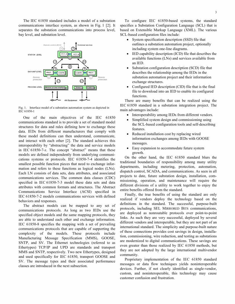
The IEC 61850 standard includes a model of a substation communications interface system, as shown in Fig. 1 [2]. It separates the substation communications into process level, bay level, and substation level.
Fig. 1. Interface model of a substation automation system as depicted in IEC 61850-1
One of the main objectives of the IEC 61850 communications standard is to provide a set of standard model structures for data and rules defining how to exchange these data. IEDs from different manufacturers that comply with these model definitions can then understand, communicate, and interact with each other [2]. The standard achieves this interoperability by “abstracting” the data and service models in IEC 61850-7-x. The concept “abstract” means that these models are defined independently from underlying communi-cations systems or protocols. IEC 61850-7-4 identifies the smallest possible function pieces that need to exchange infor-mation and refers to these functions as logical nodes (LNs). Each LN consists of data sets, data attributes, and associated communications services. The common data classes (CDC) specified in IEC 61850-7-3 model these data sets and data attributes with common formats and structures. The Abstract Communications Service Interface (ACSI) specified in IEC 61850-7-2 models communications services with defined behaviors and responses.
The abstract models can be mapped to any set of communications protocols. As long as two IEDs use the specified object models and the same mapping protocols, they are able to understand each other and exchange information. IEC 61850-8 specifies the mapping with a set of prevailing communications protocols that are capable of supporting the complexity of the models. These protocols include Manufacturing Message Specification (MMS), GOOSE, SNTP, and SV. The Ethernet technologies (referred to as Ethertypes) TCP/IP and UPD are standards and transport MMS and SNTP, respectively. Two new Ethertypes, designed and used specifically for IEC 61850, transport GOOSE and SV. The message types and their associated performance classes are introduced in the next subsection.
To configure IEC 61850-based systems, the standard specifies a Substation Configuration Language (SCL) that is based on Extensible Markup Language (XML). The various SCL-based configuration files include:
• System specification description (SSD) file that outlines a substation automation project, optionally including system one-line diagrams.
• IED capability description (ICD) file that describes the available functions (LNs) and services available from an IED.
• Substation configuration description (SCD) file that describes the relationship among the IEDs in the substation automation project and their information exchange structures.
• Configured IED description (CID) file that is the final file to download into an IED to enable its configured functions.
There are many benefits that can be realized using the IEC 61850 standard in a substation integration project. The main advantages include:
• Interoperability among IEDs from different vendors. • Simplified system design and commissioning using
the SCL-based configuration tools and self-describing features.
• Reduced installation cost by replacing wired information exchanges among IEDs with GOOSE messages.
• Easy expansion to accommodate future system growth.
On the other hand, the IEC 61850 standard blurs the traditional boundaries of responsibility among many utility departments, including metering, protection, automation, dispatch control, SCADA, and communications. As seen in all projects to date, future substation design, installation, com-missioning, operation, and maintenance will require the different divisions of a utility to work together to enjoy the entire benefits offered from the standard.
Finally, the true benefits of using the standard are only realized if vendors deploy the technology based on the definitions in the standard. The successful, purpose-built protocols, including SEL MIRRORED BITS communications, are deployed as nonroutable protocols over point-to-point links. As such they are very successful, deployed by several different vendors and interoperable, but they are not part of an international standard. The simplicity and purpose-built nature of these connections provides cost savings in design, installa-tion, commissioning, wire reduction, and testing as substations are modernized to digital communications. These savings are even greater than those realized by IEC 61850 methods, but they are not adopted by the large international multivendor community.
Proprietary implementation of the IEC 61850 standard messages or data flow techniques yields noninteroperable devices. Further, if not clearly identified as single-vendor, custom, and noninteroperable, this technology may cause customer confusion and frustration.

4
B. IEC 61850 GOOSE Messaging Two of the most useful features of the IEC 61850
communications standard are the peer-to-peer GOOSE and GSSE messages. GSSE is also known as UCA GOOSE. The difference is that while the IEC GOOSE message may include many data types like analog, binary, and integer values, the GSSE message is limited to support only a fixed structure of binary event status data.
GOOSE and GSSE messages use multicast services that allow simultaneous delivery of the same substation event message to multiple IEDs.
The GOOSE message can serve several different applica-tions that each have different performance requirements. IEC 61850 classifies application types based on how fast the messages are required to be transmitted among networked IEDs [2]. The standard also specifies the performance of each type of application, documented as time duration of message transmission. Table I lists the message types.
TABLE I IEC 61850 MESSAGE TYPES AND PERFORMANCES
Type Applications Performance Class
Requirements (Transmission
Time)
1A Fast Messages
(Trip)
P1 10 ms
P2/P3 3 ms
1B Fast Messages
(Other)
P1 100 ms
P2/P3 20 ms
2 Medium Speed 100 ms
3 Low Speed 500 ms
4 Raw Data P1 10 ms
P2/P3 3 ms
5 File Transfer ≥1000 ms
6 Time Synchronization (Accuracy)
Type 4 messages are also used for metering and power quality and meet the respective performance classes M1, M2, and M3. The Type 6 message performance requirement is dictated by the required accuracy of time synchronization. The IEC 61850 communications standard requires that the time-synchronization accuracy be ten times faster than the required time-stamp accuracy. The message speed needs to be fast and accurate enough to synchronize IED clocks to 0.1-millisecond accuracy so that IED data time stamps can be accurate to 1 millisecond. These performance classes and requirements are out of the scope of this paper.
The transmission time specified in the requirements column in Table I is the maximum time allowed for a data exchange through a communications system. This term is vague but is usefully defined as the time duration between the action of communicating a value from the logic processing of one device to the logic processing within a second device as part of an application. This transmission time is clearly illustrated in Fig. 2 (from IEC 61850-5). Time ta is the time
duration of the communications processor algorithm within the physical device (or IED) PD1. This algorithm uses data received from the input and logic processing of PD1 as the contents of messages that it creates and publishes. Detection, processing, and time-stamping of a physical contact input change of state in PD1 is a typical function represented by f1. Time tb represents the actual transit time of the message across the network between the IEDs. Time tc is the time duration of the communications processor algorithm within PD2, which receives and processes the message from PD1. The function f2 in PD2 represents processing the message contents received from PD1, subsequent closure of a physical output contact, and associated time stamp.
The time duration to create and deliver messages between IEDs via a protocol is the message transmission time represented by ttransmission = ta + tb + tc. The time duration to publish information in PD1, deliver it via a protocol message, and act on it in PD2 is the information transfer time represented by ttransfer = ttransmission + tf2. This information transfer time duration is the time truly useful to the design engineer because it represents actually performing an action as part of a communications-aided automation or protection scheme. Transfer time, ttransfer, is easily measured as the time difference between the time-stamped sequential events records (SERs) in IEDs with synchronized clocks. The time difference between the SER of detection of the input contact in PD1 and the SER of the output contact closure in PD2 represents ttransfer = ttransmission + tf2.
Therefore, ttransmission, though not measurable, is easily calculated as ttransfer – tf2 (or ttransfer – the IED processing cycle duration).
Fig. 2. Definition of transmission time (from IEC 61850-5)
GOOSE messages are Type 1 or 1A fast messages. This type of message typically uses simple binary data intended for protection and fast controls and, in some instances, analog values. These GOOSE messages are mapped directly to the previously mentioned Ethertypes to optimize their decoding and to reduce overall transmission time. Due to the multicast nature of the Ethertype and the design of Ethernet, the messages are connectionless. It is unknown what IEDs will receive the message, delivery is not guaranteed, and there is no acknowledgement from IEDs that do receive the GOOSE message. Due to the lack of an addressing layer (which was removed in order to optimize the multicast function of sending

5
one message toward many possible recipients), the GOOSE message is not routable through a WAN. It is a routable message structure (i.e., it is sent to a network address rather than a device address). However, it can only be routed inside a LAN because the network address is a mail group address and not a specific IED address. This creates network architecture challenges when protection messages must transfer between substations. Finally, this behavior means that each IED is responsible to gracefully survive message loss, duplication, delay, out-of-order delivery, and loss of connectivity.
IEC 61850-8-1 also specifies a retransmission scheme to achieve a highly dependable level of message delivery. Fig. 3 shows this mechanism of retransmission of GOOSE messages. Once started, GOOSE messages are published constantly, containing a collection of data called a data set. During configuration, each GOOSE message is given a parameter max time (mt) to wait between message publications and the name of the data set to include in the message. The data set is a collection of binary and analog data elements sent in each message. The messages are published each time one of the data set elements changes or if the mt expires. After a data set element changes, the time of transmission (tot) between mes-sages is very short (4 milliseconds), that is, the messages are sent very often to increase the likelihood that all subscribers will receive them across the nondeterministic Ethernet. After the initial rapid publications, tot grows longer until it reaches mt.
For each message, publishers calculate and include a time to live (ttl), calculated based on the next tot. Rather than simply setting ttl equal to tot, the publisher calculates a ttl to be multiples of tot to prevent nuisance alarms caused by the frequent and small Ethernet network delays. ttl is 2(tot) when tot is equal to T0 and 3(tot) when tot is any value other than T0. For the first few messages after a protection element in a data set changes state, the message is sent every 4 milliseconds and then less rapidly. Each message includes the ttl, which forecasts the time delay before the next message will be published so that subscribers can monitor correct data flow.
When a new data set event occurs (in this case, a binary change of state or an analog passing through a reporting dead band), a new message is created and published. The new data set event information is transmitted and repeated in the shortest tot (T1), as shown in Fig. 3. The retransmission time gradually increases from T2 to T3 and eventually settles at a stable retransmission time, tot = T0 = mt. This stable retrans-mission time is shortened when the next new event occurs.
Fig. 3. Example of changing time between message publications (from IEC 61850-5)
Subscribers constantly calculate time to wait (ttw), based on ttl within each message. The subscriber considers data “stale” when ttw expires and they have not received a new replacement message from the publisher.
If the subscribing IED detects expiration of the ttw, it assumes that the communication is lost and modifies its relay logic accordingly.
The message retransmission scheme is necessary to perform transmission from one to many and to allow the sub-scriber to know that the communications channel is healthy. However, depending on the choice of final stable retransmis-sion time, it may not be sufficient to guarantee the reliability of mission-critical tasks. Also, without customized use of the GOOSE message, the publisher never knows the state of the communications channel (which IEDs are receiving messages).
III. ETHERNET COMMUNICATIONS NETWORKS The IEC 61850 communications standard is based on
popular Ethernet technology (ISO/IEC 8802.3). Ethernet emerged back in the 1970s with an initial objective of connecting office computers and printers. In this section, we briefly review how Ethernet technology evolved from an office network unsuitable for real-time and mission-critical tasks to a predictable networking system that became the foundation of today’s LAN and the protocol of choice for the IEC 61850 standard.
A. IEEE C37.2 The IEEE C37.2 standard provides device numbers for
relay system components. For example, 21 is the distance relay function, and 86 is the lockout relay function. In the past, systems often deployed one relay per function; new multi-function relays perform several C37.2 functions in one device. The standard is under revision now to add Device Number 16 to represent the function of a communications device as part of a relay system. Suffix letters identify specific attributes:
• C – security processing function (virtual private network, encryption, etc.)
• F – firewall or message filter function • H – hub (obsolescent) • M – network managed function (e.g., configured via
SNMP [Simple Network Management Protocol]) • R – router • S – switch • T – telephone component (e.g., auto-answer modem)
Suffix letters can be combined, prefaced by “S” for serial or “E” for Ethernet for additional clarity. If “E” is not used, communications are EIA-232 or EIA-485. For example, a port switch on a dial-up connection is 16SS, and an Ethernet switch is 16ES.
Suffix letters can be combined to describe multifaceted or multifunctional communications devices. For example, a 16ESM is an Ethernet-managed switch, and a 16ERFCM is an Ethernet-managed router that acts as a WAN interface.
Essentially, now a switch (IEEE function 16) replaces the auxiliary relay function of past technologies.

6
B. IEEE 1613 Environmental Hardening IEEE 1613 was developed to help customers understand
and request communications devices designed to withstand the same rigors as protective relays, especially for those devices installed among, and moving data between, relays for communications-aided protection schemes. Early modems and radios did not meet these standards; new devices are now available as a consequence of the standard. The same is be-coming true for Ethernet devices that were initially developed for the office environment.
IEEE 1613 specifies that a communications device meets the following:
• Operates at least from –20 to +55 degrees C, up to –40 to +85 degrees C, with high humidity.
• No cooling fans. • Operates from station battery dc voltages with ripple. • Dielectric tests 2 kV/500 V. • 5 kV impulse tests for insulation barriers. • Oscillatory surge withstand capability (SWC) test,
2.5 kV 1 MHz decaying wave. • Fast transient SWC test, 4 kV for 50 ns. • Radio frequency interference (RFI) susceptibility test,
35 V/m from 80 MHz to 1 GHz. • Electrostatic discharge (ESD) tests as for relays,
IEEE C37.90.3. • Vibration and physical shock tests as in IEEE C37.1. • Class 1 – temporary data errors; Class 2 – no data
errors during disturbances (for relaying).
C. CSMA/CD CSMA/CD stands for carrier sense multiple access with
collision detection. In an original Ethernet LAN, many com-puters, relays, or other devices, each with a network interface card (NIC), connect together to one physical medium, such as a coaxial cable. When a relay needs to respond to a request or send unsolicited data on the network, it will detect if there is data transmission already on the media. If the relay does not sense any carrier, it then starts to transmit data. Computer and relay networks consist of multiple devices attached to the same media and doing the same thing. Therefore, it is un-avoidable that two or more devices may try to send data on the same media at the same time. Collision occurs. In such a situation, each device detects the collision, stops transmitting, waits a random time to reduce the likelihood of causing a second collision, and starts retransmission. This process is CSMA/CD.
When the number of computers or IEDs connected to the same communications segment increases, the likelihood of data collisions increases exponentially. As well as introducing prolonged data transmission delays, frequent data collisions may also drop data packets and cause unpredictable network behaviors. Modern switched Ethernet uses separate, new communications IEDs, Ethernet switches, to reduce or eliminate data collisions.
An Ethernet switch is an IED itself and has an operating system and firmware, multiple required settings, power supply, and multiple Ethernet ports. Each port connects to one
computer or IED and forms a small network segment. This configuration eliminates the shared medium among multiple devices. With the use of twisted pairs and fiber cables that separate the transmitted and received traffic, modern switched Ethernet LANs create a truly full-duplex and collision-free communications environment.
An Ethernet switch keeps a list of media access control (MAC) addresses of each device it connects to. It talks to all devices connected to it simultaneously. When receiving a message from a port, the switch examines the destination MAC address of the message and forwards it only to the port with a device that matches the address. This switching mechanism in today’s Ethernet speeds up the data transmis-sion and makes 100 Mbps networks quite standard and gigabit networks possible. This method works for client-server traffic such as SCADA poll and response using MMS; however, it does not work for GOOSE. It was described previously that the GOOSE message was modified to behave in a multicast mode without knowledge of the destination MAC addresses. Therefore, GOOSE messages are published to a group multicast address, which goes to every port.
An Ethernet switch processes every message received or transmitted by each port. It takes time for switches to process messages, and this introduces a short but unavoidable switch processing latency delay. If a switch cannot process and forward all the messages it receives, a backlog occurs. A message will wait in a transmitting memory queue for its turn to be sent out. If this occurs, there is a switch queue latency in addition to the switch processing latency. A message may need to go through several switches in a network to reach its destination. The communications system transfer time t, shown in Fig. 2, will be the sum of all switch delays in a message path in the worst network configuration scenarios. When designed with knowledge and care, the likelihood of a switch queue delay is minimized but not eliminated.
D. IEEE 801.2Q – Priority Tagging/VLAN GOOSE is an example of an Ethernet multicast/broadcast
message. One device sends out this message intended for a group of devices on the network in the multicast case and for every device on the network in the broadcast case. The IEC 61850 GOOSE messages are specified as multicast mes-sages. When an IED receives a GOOSE message, it has to decode the message and see if it has previously been configured to subscribe to and receive each message. Multicast/broadcast messages on Ethernet increase the network traffic. When a switch receives such a message, it forwards it on to all the ports except the one from which it received the message. Large numbers of broadcast messages quickly fill the available network bandwidth. One of the tech-niques to alleviate the network burden of multicast/broadcast messages is the virtual local-area network (VLAN). IEEE extended the Ethernet Standard 802.1 with the designator Q for message quality, which includes extensions for optional VLAN and message priority information. IEEE 802.1Q VLAN divides a physically connected network into several virtual LANs, as shown in Fig. 4. VLANs originated from a

7
need to segregate network traffic from different departments inside one enterprise. While keeping the sensitive information private, VLAN techniques restrict traffic flow of multicast/broadcast messages to a single individual VLAN and therefore the devices within it.
Fig. 4. Switched Ethernet and VLAN configuration
Another technique to reduce network congestion caused by multicast/broadcast messages is to use priority tagging per IEEE 802.1P. Fig. 5 shows the VLAN/priority tag in an Ethernet frame. When there is a transmission backlog in a switch, the switch examines the user priority part of the tag and transmits frames with a higher priority first. The IEC 61850-8-1 standard specifies that default GOOSE messages should have a priority level of 4. However, network designers and protection engineers can choose any value between 0 and 7 to separate the GOOSE messages by order of
importance. It is important to know, however, that though relays support eight unique priorities, most switches do not. Care must be taken to understand and set relays and the switch, acting as an auxiliary in a protection scheme, to use these parameters correctly.
E. Network Redundancy In order to achieve high dependability, protection for high-
voltage lines and equipment normally requires a redundant system: primary and backup protection (e.g., a current differential relay for the primary protection and permissive overreaching transfer trip with a residual overcurrent as the backup protection for a transmission line). It would not be complete to discuss Ethernet systems used for real-time protection and control without mentioning the redundancy requirement.
Substation hardening requirements specified in the IEEE 1613-2003 standard provide methods to best choose the network equipment suitable for the harsh substation environ-ment. A looped network configuration or multiple paths between two points in a network provide redundancy to Ethernet LAN.
The Rapid Spanning Tree Protocol (RSTP) in a switch manages multiple communications paths and reconfigures the system topology in case of a physical path failure, such as a cut cable, failed port, or loose connection. This type of redundancy will not prevent a network outage if a switch fails or is out for maintenance or network expansion.
Fig. 5. Ethernet VLAN and priority tag

8
Completely separate and redundant LANs that eliminate the single point of failure of a switch are also possible via many different configurations. One such configuration that provides total redundancy, two identical networks in place for mission-critical protection and control, is shown in Fig. 6 [3]. IEDs often have two Ethernet ports and a failover mechanism, that is, if one port fails, the IED automatically switches to use the backup port. The newest generation of IEDs have dual primary ports that are simultaneously connected to two differ-ent LANs without failover. This dual-port configuration is a perfect setup for two redundant communications networks. The two networks can be interconnected to mutually check the network health and share some network traffic in case of a partial failure of one network.
Fig. 6. Fully redundant LAN system for protection and control [3]
IV. IEC 61850 APPLICATION IN PROTECTION AND CONTROL Ever since the first microprocessor distance relay with a
fault locator appeared in early 1980s, people have gone through a period of reservations before accepting the new technology. With their advantages of integrating measure-ments, protection, automation, and control, performing contin-uous self-tests, and providing abundant information for system planning, operating, and maintenance, microprocessor relays or IEDs are enjoying wide application at all levels of power substations. In addition to traditional protection theories and applications, protection engineers have learned such new terms as data rate, MIRRORED BITS communications, and protocols that are related to microprocessor devices. With the new ingredients of IEC 61850 targeted to protection and real-time controls, protection engineers will once again have to understand more computer and communications network terms in order to gain the full benefit of the standard.
In this section, we group traditional protection schemes into two categories according to their communications re-quirements in terms of distance (within a substation or inter-substation) and data volume (single bit [binary] or continuous analog data). We discuss how the present IEC 61850 standard and its future extension will accomplish or improve traditional protection schemes.
A. Protection Schemes That Require Inter-IED Message Exchange Within a Substation
The following subsections describe some protection and control schemes that require information exchange between IEDs within a substation. These are typical applications where the GOOSE protection and control messages replace the hard wires and provide the same communication through an Ethernet LAN.
1) Fast Bus Tripping The fast bus tripping scheme typically applies to radial
distribution systems to achieve a clearance time for bus faults that is close to a bus differential scheme. This scheme is also referred to as reverse interlocking.
Fig. 7 shows the arrangement of a fast bus tripping scheme. The bus IED for the bus high-side breaker communicates with feeder IEDs about the location of a fault. If a fault occurs on a feeder, one of the feeder IEDs will detect the fault and issue a signal to block the fast tripping element in the bus IED. Otherwise, if a fault occurs on the bus, no feeder IEDs see the fault and block the bus IED, and the bus IED trips the bus using the fast overcurrent elements. A traditional fast bus scheme uses the IED contact input and output to communicate the fault information.
Bus IED
Fdr IED1
Fdr IED2
Fdr IED3
Fig. 7. Fast bus tripping scheme for distribution substation with radial feeders
2) Reclosing Control Modern IEDs typically incorporate both protection and
control functions like breaker reclosing. Most IEDs have sophisticated control schemes for two breakers to be used in the breaker-and-a-half and ring bus arrangements. Neverthe-less, many utilities use a dedicated IED to perform reclosing, breaker failure protection, and other functions for a specific breaker bay. In this situation, the trip signal of the protection IED initiates the reclosing IED through a hard-wire connection.

9
3) Breaker Failure Protection Local breaker failure backup protection is common for
high-voltage applications. As in the case of reclosing control, today’s IEDs typically have breaker failure protection built in, in addition to complete protection functions. When the IED issues a trip, it starts a timer and monitors the breaker current. If the current does not go away in a preset time, the IED issues a retrip or trips the adjacent breakers to isolate the faulted one. However, as in the case of the reclosing control, if a user wants to treat the breaker as a bay and perform the bay controls and protection, a dedicated IED can be used for breaker failure protection. The dedicated IED could monitor additional breaker conditions such as the gas pressure and the ambient temperature for a point-on-wave control purpose. The breaker failure initiation signal is passed from the protection IED to the breaker failure IED, using contact inputs and outputs and hard wires.
4) IEC 61850 GOOSE Applications Within a Substation The IEC 61850 standard was designed initially for com-
munications inside a substation. The traditional application schemes such as those outlined above are perfect applications for IEC 61850 GOOSE to replace wired communications channels and reduce engineering design, implementation, operation, and maintenance costs.
Rather than simply replacing the hard wires, GOOSE messages can also monitor the health of the virtual wires. This is similar to the self-test functions of microprocessor IEDs, to avoid situations where a failed device is not noticed until it is called on to protect power equipment.
The retransmission built into GOOSE messages, shown in Fig. 3, is one mechanism to ensure knowledge of the health of a channel periodically to the receiving end of the channel. Without an event change, the prior GOOSE message is pub-lished every T0 seconds in the steady state. The subscribing IED monitors this message and sends out an alarm GOOSE message, notifies SCADA, modifies its internal logic, presents an alarm LED and description on the front panel, and sends an email message to the protection engineer if the message is not received within a prescribed time as appropriate.
However, a channel may still fail between a new event and the time the last message was received. The possibility of this unchecked failure is proportional to the length of T0, which is typically one second. For mission-critical protection and control functions, a user may want to reduce this T0 or build a message acknowledgement mechanism and a backup plan [4].
Another possible failure mode is a dropped Ethernet packet or frame. Again, the retransmission of the GOOSE message increases the dependability of an eventual message reception in the event a packet is dropped due to high volume of Ethernet traffic or interference from control and power cabling sharing a cable tray with Ethernet cable. For time-critical applications like breaker failure, protection engineers need to clearly specify the timing requirement so the network engineer can size the network traffic and ensure the success rate of the first GOOSE message reception.
B. Protection Schemes That Require Intersubstation Communication
The present scope of IEC 61850 is limited to communi-cations within a substation. Work is underway to extend the IEC 61850 standard to cover intersubstation communications requirements.
The following subsections describe some of the protection schemes that require information exchange between IEDs residing in different substations and could benefit from the existing standard and its future extension.
1) Directional Comparison Schemes Directional comparison schemes are typically line protec-
tion schemes that use minimal information exchange between relays at two ends of the line [5]. The protection elements used in these schemes are either directional overcurrent elements or distance elements.
In a directional comparison blocking (DCB) scheme, the relay at one end of the line uses reverse-looking elements to block the relay from tripping at the other end by sending a blocking signal. An on/off power line carrier channel is normally used for this scheme. Keying the channel to the “on” state represents a block signal. Since a trip does not rely on the channel being at the “on” state, this scheme works dependably for faults occurring on the section of the protected line, even if these faults interrupt the channel.
In a permissive overreaching transfer trip (POTT) scheme, the relay uses an overreaching element that detects a fault in the forward direction beyond its protection line section to send a transfer trip signal to the relay at the other end. If the relay at the other end also picks up its overreaching element, it then trips the breaker and sends a transfer trip signal at the same time. This scheme typically uses a dedicated communications channel like a phone line or a microwave channel to send two signals: guard and trip. The guard signal is on the channel continuously for monitoring purposes when there is no transfer trip condition. The channel stops the guard signal and sends the trip signal when it receives the transfer trip from a relay. If the channel detects a loss of the guard signal while not receiving the trip within a settable window, it issues an alarm and disables the POTT scheme.
A directional comparison unblocking (DCUB) scheme is similar to the POTT scheme in that it uses an overreaching element to stop the guard signal and transmit the trip signal. If a relay picks up its overreaching protection element and receives a trip signal at the same time, it trips the local line breaker. The DCUB scheme is also different from the POTT scheme because it opens a window after the loss of the guard and before the reception of the trip. During this window, the scheme behaves like the DCB scheme in that it allows tripping the line if the overreaching element picks up. After this time window, the channel issues an alarm and disables the scheme. Because of this feature of allowing a trip without the channel (no guard and no trip signals), the DCUB scheme can use the power line carrier as the communications channel.

10
It is obvious that choosing the type of traditional direc-tional comparison scheme depends on the characteristics of the communications channel available. In protection schemes like POTT and DCUB that depend on the presence of the transfer trip signal, continuous channel monitoring is used to ensure its availability. While the needed attentions spelled out in the previous section still hold true for GOOSE to be applied to directional comparison schemes, other types of hybrid directional comparison schemes can be designed [5] to accom-modate the special characteristics of the GOOSE messages and the Ethernet.
Until the IEC 61850 communications standard is modified to include methods to make GOOSE messages that are addressable over a WAN, there are two mechanisms to bring GOOSE messages from one substation to the other substation [6]. Ethernet tunneling is a way to establish a secure channel through a public WAN. A virtual private network (VPN) is an example of such a secured channel. The process essentially establishes the behavior of IEDs in a local substation inter-acting with IEDs in a remote substation as if they were on the same LAN.
2) Line Current Differential Scheme A line current differential protection scheme compares
current samples from two ends of a line. With through-line load flow only, these current samples are equal. An in-section line fault causes a mismatch of these current samples, and the scheme detects the fault and issues a trip. Compared with distance protection, the current differential element has the advantages of avoiding problems associated with potential transformers and not being affected by system swings. Line current differential protection, however, requires a communi-cations channel with high bandwidth. As their cost reduces over time, fiber-optic channels are increasingly available to power system protection. A line current differential protection scheme therefore gains wider applications. Many utilities specify the line current differential as both primary and backup protection for their high-voltage transmission line protection, with distance protection as a backup.
The line current differential protection normally transmits current samples without a time tag on a 64 kbit/s DS0 channel that is multiplexed to the synchronous optical network (SONET). Unlike the packet mode of Ethernet, SONET operates in a circuit mode in which each connection achieves constant bit rate and time delay. The current differential scheme uses a ping-pong process to estimate the one-way channel delay and uses the information to align the currents from both ends of a line together.
Even with tunneling extension to WAN, the existing IEC 61850 GOOSE is not suitable for current differential protection, which relies on a constant stream of “current” values. The SV messages specified in IEC 61850-9-2 could offer a solution when extended to intersubstation transmission. The data alignment of the present current differential element design will have to change to take advantage of the time tags included in the SV.
V. CONCLUSION As a standard that has gained fast attention and wide
application, IEC 61850 is certainly here to stay for the foreseeable future in power substation integration, automation, and control. Applied to substation protection and control, the new standard brings the benefits of cost savings in engineering design, installation, commissioning tests, operation, and maintenance.
Power protection engineers will have to learn the new technology, terms, and substation paradigms just as they did when microprocessor IEDs gained popularity in the early 1980s. They will have to work even closer with engineers from their communications and/or information technology departments, be able to provide protection and control specifi-cations under the new communications environment, and be able to strike the best compromise between protection/control performance and communications network complexity.
IEC 61850 GOOSE is an event-driven broadcasting message that has a built-in retransmission mechanism to increase its dependability. The standard specifies that Type 1A GOOSE with the P2/P3 performance class should have a 3-millisecond, back-to-back transmission time suitable for substation protection and critical control.
Ethernet has evolved from the initial CSMA/CD to today’s switched Ethernet that is almost collision free. The priority tag further reduces the network transmission delay time for critical messages. Ethernet now can be designed with de-terministic transmission time suitable for real-time substation protection and control.
While relying on the IEC 61850 GOOSE specifications and Ethernet features to ensure high reliability of protection schemes using GOOSE messages, protection engineers may want to apply other mechanisms to further enhance the relia-bility for critical protection functions like fast bus trip and breaker failure. These mechanisms include redundant Ethernet structures and message acknowledgements.
The existing IEC 61850 standard covers communications requirements only within a substation. Nevertheless, tradi-tional directional comparison protection schemes could be implemented using proxy and tunneling techniques. Protection engineers may want to reconsider traditional DCB, POTT, and DCUB schemes while applying them on the new communica-tions channels. Other new hybrid comparison schemes may be designed considering the unique characteristics of GOOSE over Ethernet.
The increasingly popular line current differential protection for EHV/UHV power systems will have to wait for the work that is presently underway to extend the standard to cover intersubstation communications requirements. Extending the SV messages specified in IEC 61850-9-2 to intersubstation may offer a solution for line current differential protection. The time tagging included in SV may change future line current differential protection design as well.

11
VI. REFERENCES [1] V. M. Flores, D. Espinosa, J. Alzate, and D. Dolezilek, “Case Study:
Design and Implementation of IEC 61850 From Multiple Vendors at CFE La Venta II,” proceedings of the 9th Annual Western Power Delivery Automation Conference, Spokane, WA, April 2007. Available: http://www.selinc.com/techpprs.htm.
[2] IEC 61850 Standard. Available: http://www.iec.ch. [3] E. A. Udren, “IEEE (ANSI) Device Number 16 – Ethernet Switches and
Routers.” [4] V. Skendzic and A. Guzmán, “Enhancing Power System Automation
Through the Use of Real-Time Ethernet,” proceedings of the 15th Annual DistribuTECH, San Diego, CA, January 2005. Available: http://www.selinc.com/techpprs.htm.
[5] E. O. Schweitzer, III, and J. J. Kumm, “Statistical Comparison and Evaluation of Pilot Protection Schemes,” proceedings of the 23rd Annual Western Protective Relay Conference, Spokane, WA, October 1996. Available: http://www.selinc.com/techpprs.htm.
[6] V. Skendzic and R. Moore, “Extending the Substation LAN Beyond Substation Boundaries: Current Capabilities and Potential New Protection Applications of Wide-Area Ethernet,” proceedings of the 8th Annual Western Power Delivery Automation Conference, Spokane, WA, April 2006.
VII. BIOGRAPHIES Daqing Hou received B.S. and M.S. degrees in Electrical Engineering at the Northeast University, China, in 1981 and 1984, respectively. He received his Ph.D. in Electrical and Computer Engineering at Washington State University in 1991. Since 1990, he has been with Schweitzer Engineering Laboratories, Inc., Pullman, Washington, USA, where he has held numerous positions in-cluding development engineer, application engineer, and R&D manager. He is currently a principal research engineer. His work includes system modeling, simulation, and signal processing for power systems and digital protective relays. His research interests include multivariable linear systems, system identification, and signal processing. He holds multiple patents and has au-thored or coauthored many technical papers. He is a Senior Member of IEEE.
Dave Dolezilek is the technology director of Schweitzer Engineering Laboratories, Inc. He is an electrical engineer, BSEE Montana State University, with experience in electric power protection, integration, automation, communications, controls, SCADA, and EMS. He has authored numerous technical papers and continues to research innovative technology affecting our industry. Dolezilek is a patented inventor and participates in numerous working groups and technical committees. He is a member of IEEE, the IEEE Reliability Society, CIGRE working groups, and two International Electrotechnical Commission (IEC) technical committees tasked with global standardization and security of communications networks and systems in substations.
© 2008 by Schweitzer Engineering Laboratories, Inc. All rights reserved.
20080912 • TP6335-01