iec 62591 wireless interface instruction manual/media/resources/emerson...iec 62591 wireless...
TRANSCRIPT

Remote Automation Solutions
Part D301708X012 August 2015
IEC 62591 Wireless Interface Instruction Manual
IEC 62591 Wireless Interface Instruction Manual
ii Revised August-2015
Revision Tracking Sheet August 2015
This manual may be revised periodically to incorporate new or updated information. The revision date of each page appears at the bottom of the page opposite the page number. A change in revision date to any page also changes the date of the manual that appears on the front cover. Listed below is the revision date of each page (if applicable):
Page Revision All August-2015 All October-2014 Initial issue August-2012

IEC 62591 Wireless Interface Instruction Manual
Revised August-2015 iii
Contents Chapter 1 – General Information 1-1
1.1 Scope of Manual ............................................................................................................................ 1-2 1.2 Hardware ........................................................................................................................................ 1-2
1.2.1 IEC 62591 Wireless Interface Module ............................................................................... 1-2 1.2.2 Smart Wireless Field Link .................................................................................................. 1-3 1.2.3 WirelessHART Field Devices ............................................................................................. 1-4
1.3 Configuration/Commissioning Software ......................................................................................... 1-4 1.4 Additional Technical Information .................................................................................................... 1-5
Chapter 2 – Installation 2-1
2.1 Installing the IEC 62591 Module .................................................................................................... 2-1 2.2 Installing the Smart Wireless Field Link ......................................................................................... 2-3
2.2.1 Optimizing the Location ...................................................................................................... 2-3 2.2.2 Positioning the Antenna ..................................................................................................... 2-4 2.2.3 Mounting the Field Link ...................................................................................................... 2-4 2.2.4 Grounding the Field Link .................................................................................................... 2-5
2.3 Wiring the Module and Field Link ................................................................................................... 2-5 2.3.1 Wiring the Field Link ........................................................................................................... 2-5 2.3.2 Wiring the IEC 62591 Module to the Field Link.................................................................. 2-6
2.4 Preparing for Configuration and Commissioning ........................................................................... 2-7
Chapter 3 – Configuration and Commissioning 3-1
3.1 Overview ........................................................................................................................................ 3-2 3.1.1 Configuring Devices and Planning the Network ................................................................. 3-2 3.1.2 Network ID and Join Key .................................................................................................... 3-3 3.1.3 Rosemount THUM™ Adapter ............................................................................................. 3-3
3.2 IEC 62591 Module Interface (FB107) ............................................................................................ 3-3 3.2.1 Commissioning Devices ..................................................................................................... 3-7 3.2.2 Managing Device Information .......................................................................................... 3-10 3.2.3 Reviewing Network Statistics ........................................................................................... 3-13 3.2.4 Retrieving a Diagnostic Log ............................................................................................. 3-14 3.2.5 Displaying Commissioned Transmitters ........................................................................... 3-15 3.2.6 Updating Firmware ........................................................................................................... 3-16
3.3 IEC 62591 Module Interface (ROC800) ....................................................................................... 3-18 3.3.1 Accessing the Network ..................................................................................................... 3-20 3.3.2 Commissioning Devices ................................................................................................... 3-21 3.3.3 Managing Device Information .......................................................................................... 3-25 3.3.4 Viewing Network Statistics ............................................................................................... 3-28 3.3.5 Retrieving a Diagnostic Log ............................................................................................. 3-29 3.3.6 Updating Firmware ........................................................................................................... 3-30
Chapter 4 – Troubleshooting 4-1
4.1 General Guidelines ........................................................................................................................ 4-1 4.2 Common Troubleshooting Techniques .......................................................................................... 4-2
4.2.1 Identifying which System Components are Working ......................................................... 4-2 4.2.2 Conducting Basic Hardware Checks ................................................................................. 4-2 4.2.3 Looking for Possible Configuration Errors ......................................................................... 4-2

IEC 62591 Wireless Interface Instruction Manual
iv Revised August-2015
4.2.4 Rebooting after a Power Loss ............................................................................................. 4-3 4.3 Errors from the IEC 62591 Transmitter Tab .................................................................................... 4-3
4.3.1 NaN value ........................................................................................................................... 4-3 4.3.2 Stale / Communication Failure ............................................................................................ 4-4
Appendix A – Glossary A-1
Index I-1
IEC 62591 Wireless Interface Instruction Manual
Revised August-2015 General Information 1-1
Chapter 1 – General Information
In This Chapter
1.1 Scope of Manual .................................................................................... 1-2 1.2 Hardware ............................................................................................... 1-2
1.2.1 IEC 62591 Wireless Interface Module ........................................ 1-3 1.2.2 Smart Wireless Field Link ........................................................... 1-3 1.2.3 WirelessHART Field Devices ..................................................... 1-4
1.3 Configuration/Commissioning Software ................................................ 1-4 1.4 Additional Technical Information............................................................ 1-5
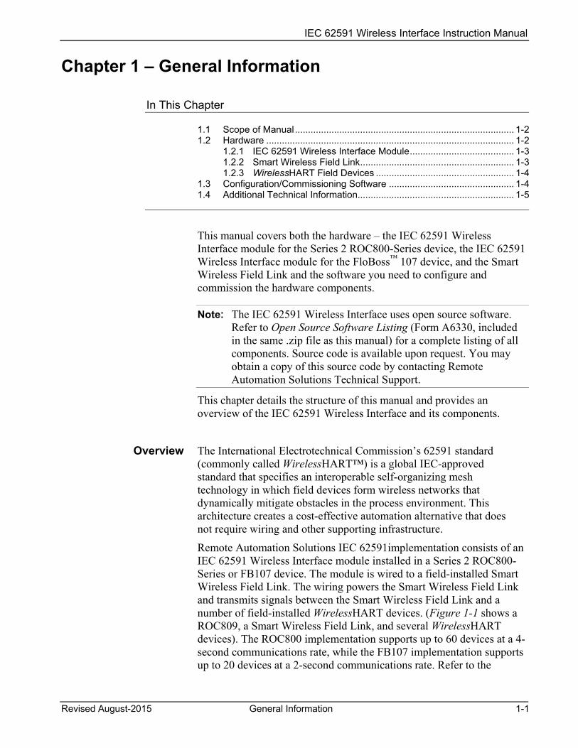
This manual covers both the hardware – the IEC 62591 Wireless Interface module for the Series 2 ROC800-Series device, the IEC 62591 Wireless Interface module for the FloBoss™ 107 device, and the Smart Wireless Field Link and the software you need to configure and commission the hardware components.
Note: The IEC 62591 Wireless Interface uses open source software. Refer to Open Source Software Listing (Form A6330, included in the same .zip file as this manual) for a complete listing of all components. Source code is available upon request. You may obtain a copy of this source code by contacting Remote Automation Solutions Technical Support.
This chapter details the structure of this manual and provides an overview of the IEC 62591 Wireless Interface and its components.
Overview The International Electrotechnical Commission’s 62591 standard (commonly called WirelessHART™) is a global IEC-approved standard that specifies an interoperable self-organizing mesh technology in which field devices form wireless networks that dynamically mitigate obstacles in the process environment. This architecture creates a cost-effective automation alternative that does not require wiring and other supporting infrastructure.
Remote Automation Solutions IEC 62591implementation consists of an IEC 62591 Wireless Interface module installed in a Series 2 ROC800-Series or FB107 device. The module is wired to a field-installed Smart Wireless Field Link. The wiring powers the Smart Wireless Field Link and transmits signals between the Smart Wireless Field Link and a number of field-installed WirelessHART devices. (Figure 1-1 shows a ROC809, a Smart Wireless Field Link, and several WirelessHART devices). The ROC800 implementation supports up to 60 devices at a 4-second communications rate, while the FB107 implementation supports up to 20 devices at a 2-second communications rate. Refer to the

IEC 62591 Wireless Interface Instruction Manual
1-2 General Information Revised August-2015
product data sheets for each device for additional device/communication rate values.
Figure 1-1. IEC 62591 Field Installation
1.1 Scope of Manual This manual contains the following chapters:
Chapter 1 General Information
Provides an overview of the hardware for the IEC 62591 Wireless Interface.
Chapter 2 Installation
Provides information on installing the IEC 62591 Wireless Interface modules, installing the Smart Wireless Field Link, and wiring the Smart Wireless Field Link to the module.
Chapter 3 Configuring and Commissioning
Provides information using ROCLINK 800 to configure and commission the Wireless Interface.
Chapter 4 Troubleshooting
Provides information on diagnosing and correcting problems for the IEC 62591 Wireless Interface.
Index Provides an alphabetic listing of items and topics contained in this manual.
1.2 Hardware The IEC 62591 Wireless Interface has two basic components: the IEC 62591 Wireless Interface module (“module”) and the Smart Wireless Field Link (“Field Link”).
IEC 62591 Wireless Interface Instruction Manual
Revised August-2015 General Information 1-3
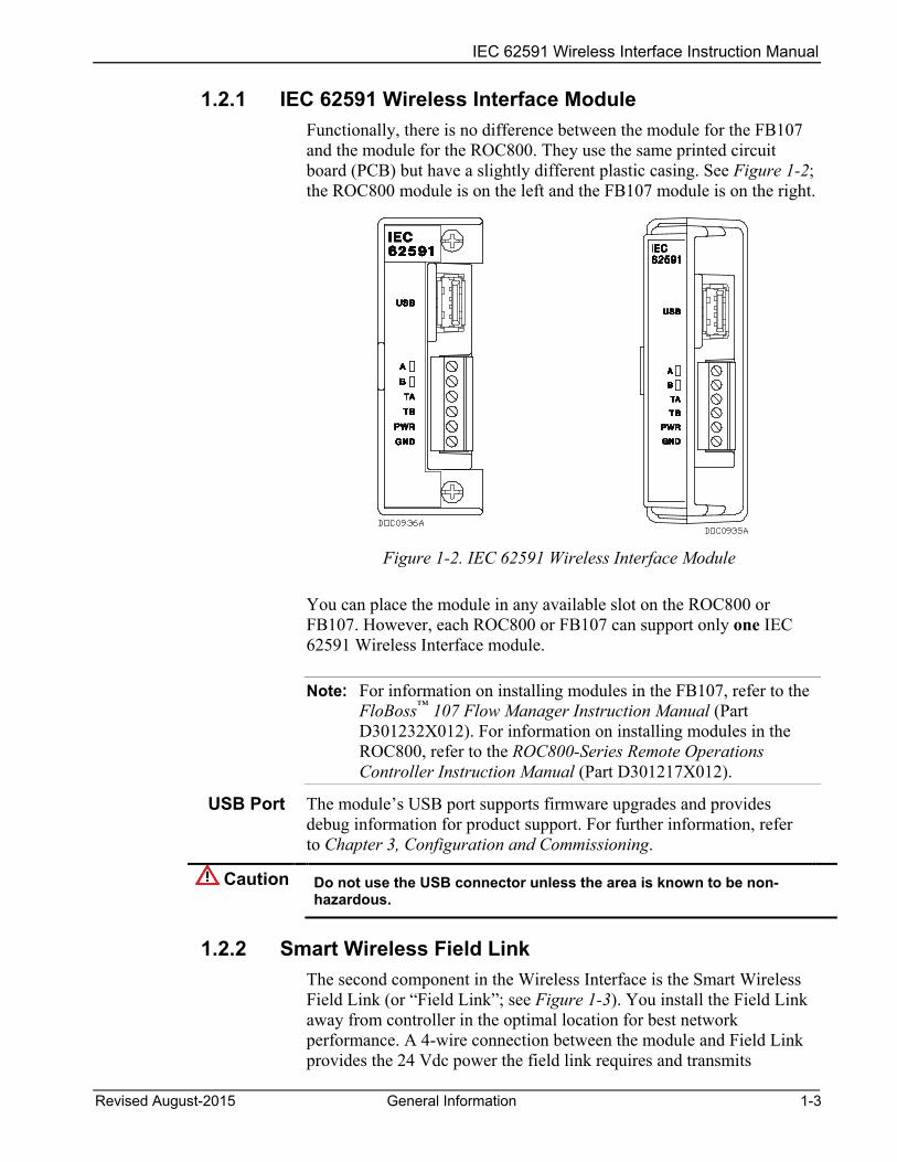
1.2.1 IEC 62591 Wireless Interface Module Functionally, there is no difference between the module for the FB107 and the module for the ROC800. They use the same printed circuit board (PCB) but have a slightly different plastic casing. See Figure 1-2; the ROC800 module is on the left and the FB107 module is on the right.
Figure 1-2. IEC 62591 Wireless Interface Module
You can place the module in any available slot on the ROC800 or FB107. However, each ROC800 or FB107 can support only one IEC 62591 Wireless Interface module.
Note: For information on installing modules in the FB107, refer to the FloBoss™ 107 Flow Manager Instruction Manual (Part D301232X012). For information on installing modules in the ROC800, refer to the ROC800-Series Remote Operations Controller Instruction Manual (Part D301217X012).
USB Port The module’s USB port supports firmware upgrades and provides debug information for product support. For further information, refer to Chapter 3, Configuration and Commissioning.
Caution Do not use the USB connector unless the area is known to be non-hazardous.
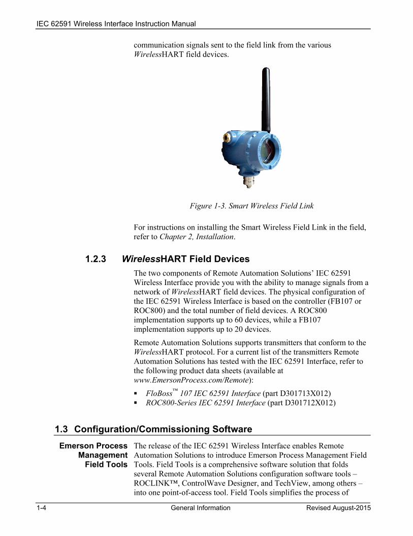
1.2.2 Smart Wireless Field Link The second component in the Wireless Interface is the Smart Wireless Field Link (or “Field Link”; see Figure 1-3). You install the Field Link away from controller in the optimal location for best network performance. A 4-wire connection between the module and Field Link provides the 24 Vdc power the field link requires and transmits
IEC 62591 Wireless Interface Instruction Manual
1-4 General Information Revised August-2015
communication signals sent to the field link from the various WirelessHART field devices.
Figure 1-3. Smart Wireless Field Link
For instructions on installing the Smart Wireless Field Link in the field, refer to Chapter 2, Installation.
1.2.3 WirelessHART Field Devices The two components of Remote Automation Solutions’ IEC 62591 Wireless Interface provide you with the ability to manage signals from a network of WirelessHART field devices. The physical configuration of the IEC 62591 Wireless Interface is based on the controller (FB107 or ROC800) and the total number of field devices. A ROC800 implementation supports up to 60 devices, while a FB107 implementation supports up to 20 devices.
Remote Automation Solutions supports transmitters that conform to the WirelessHART protocol. For a current list of the transmitters Remote Automation Solutions has tested with the IEC 62591 Interface, refer to the following product data sheets (available at www.EmersonProcess.com/Remote):
FloBoss™ 107 IEC 62591 Interface (part D301713X012) ROC800-Series IEC 62591 Interface (part D301712X012)
1.3 Configuration/Commissioning Software Emerson Process
Management
Field Tools
The release of the IEC 62591 Wireless Interface enables Remote Automation Solutions to introduce Emerson Process Management Field Tools. Field Tools is a comprehensive software solution that folds several Remote Automation Solutions configuration software tools – ROCLINK™, ControlWave Designer, and TechView, among others – into one point-of-access tool. Field Tools simplifies the process of

IEC 62591 Wireless Interface Instruction Manual
Revised August-2015 General Information 1-5
configuring both wired and wireless HART devices. Once you have installed the IEC 62591 modules and wired them to the Smart Wireless Field Link, you use Field Tools to configure and then commission (“activate”) the entire network. Refer to Chapter 3, Configuring and Commissioning, for specific instructions.
1.4 Additional Technical Information Refer to the following technical documentation (available at www.EmersonProcess.com/Remote) for additional technical and most-current information:
Table 1-1. Additional Technical Information
Name Form Number Part Number ROC800-Series IEC 62591 Interface Product Data Sheet ROC800:62591 D301712X012 FloBoss™ IEC 62591 Interface Product Data Sheet FB107:62591 D301713X012 FloBoss™ 107 Flow Manager Instruction Manual A6206 D301232X012 ROC800-Series Remote Operations Controller Instruction Manual
A6175 D301217X012

IEC 62591 Wireless Interface Instruction Manual
1-6 General Information Revised August-2015
[This page is intentionally left blank.]

IEC 62591 Wireless Interface Instruction Manual
Revised August-2015 Installation 2-1
Chapter 2 – Installation
In This Chapter
2.1 Installing the IEC 62591 Module ...................................................... 2-1 2.2 Installing the Smart Wireless Field Link ........................................... 2-3
2.2.1 Optimizing the Location ........................................................ 2-3 2.2.2 Positioning the Antenna ....................................................... 2-4 2.2.3 Mounting the Field Link ........................................................ 2-4 2.2.4 Grounding the Field Link ...................................................... 2-5
2.3 Wiring the Module and Field Link .................................................... 2-5 2.3.1 Wiring the Field Link ............................................................. 2-5 2.3.2 Wiring the IEC 62591 Module to the Field Link .................... 2-6
2.4 Preparing for Configuration and Commissioning ............................. 2-7
This chapter describes installing the IEC 62591 module in either a ROC800 or FB107, installing the Smart Wireless Field Link, and connecting the Smart Wireless Field Link to the IEC 62591 Wireless Interface module.
Note: This chapter covers the physical installation process. To configure and commission the IEC 62591 Wireless Interface, refer to Chapter 3, Configuring and Commissioning.
2.1 Installing the IEC 62591 Module You install the IEC 62591 Wireless Interface module in a Series 2 ROC800 or FB107 as you would any other module. However, you can install only one IEC 62591 module in either device.
ROC800 To install a module in the Series 2 ROC800:
Caution If any processes require backup, arrange for that before removing power from the device.
1. Remove power from the device.
2. Remove the wire channel cover.
Note: Leaving the wire channel cover in place can prevent the module from correctly connecting to the socket on the backplane.
3. Perform one of the following:
If a module is currently in the slot, unscrew the captive screws and remove that module. Store it in an anti-static bag.
If the slot is currently empty, remove and store the module cover.

IEC 62591 Wireless Interface Instruction Manual
2-2 Installation Revised August-2015
4. Insert the module through the module slot in the front of the ROC800 or EXP housing. Make sure that the label on the front of the module faces right side up (see Figure 1-2). Gently slide the module in place until it contacts properly with the connectors on the backplane.
Note: If the module stops and does not go any farther, do not force the module. Remove the module and see if the pins are bent. If the pins are bent, gently straighten the pints and re-insert the module. The back of the module must connect fully with the connectors on the backplane.
5. Tighten the captive screws on the front of the module.
6. Wire the module to the Smart Wireless Field Link (refer to Wiring the Modules and Field Link section in this chapter).
7. Replace the wire channel cover.
Caution Never connect the sheath surrounding shielded wiring to a signal ground terminal or to the common terminal of an I/O module. Doing so makes the module susceptible to static discharge, which can permanently damage the module. Connect the shielded wiring sheath only to a suitable earth ground.
FB107 To install a module in the FB107:
Caution If any processes require backup, arrange for that before removing power from the device.
1. Remove power from the device. 2. Perform one of the following:
If a module is currently in the desired slot, remove the module and store it in an anti-static bag.
If the slot is currently empty, remove and store the module cover.
Note: When you install an IEC 62591 module in the FB107’s slot 2, the firmware redirects the COM2 communications port on the CPU to the module installed in slot 2. To prevent this from occurring, install the module in slot 3 through slot 7.
3. Close the module cover (the piece with ridged edges) against the body of the module. This enables the locking mechanism to secure the module in the slot.
4. Insert the module in the slot on the base unit or expansion rack, making sure that the module faces the correct direction (see Figure 1-2). Gently slide the module into place until it contacts properly with the connectors on the backplane.

IEC 62591 Wireless Interface Instruction Manual
Revised August-2015 Installation 2-3
Note: If the module stops and does not go any farther, do not force the module. Remove the module and see if the pins are bent. If the pins are bent, gently straighten the pints and re-insert the module. The back of the module must connect fully with the connectors on the backplane.
5. Wire the module to the Smart Wireless Field Link (refer to Wiring the Modules and Field Link section in this chapter).
Caution Never connect the sheath surrounding shielded wiring to a signal ground terminal or to the common terminal of an I/O module. Doing so makes the module susceptible to static discharge, which can permanently damage the module. Connect the shielded wiring sheath only to a suitable earth ground.
6. Proceed to Installing the Smart Wireless Field Link.
2.2 Installing the Smart Wireless Field Link This section covers where and how to install the Smart Wireless Field Link.
2.2.1 Optimizing the Location Mount the Smart Wireless Field Link in a location that provides convenient access to the host system network (wireless I/O devices) and the network of wireless field devices. Find a location where the Field Link has optimal wireless performance. Ideally, this is 4.6 to 7.6 m (15-25 ft) above the ground or 2 m (6 ft) above obstructions or major infrastructures. See Figure 2-1.
Figure 2-1. Mounting the Field Link

IEC 62591 Wireless Interface Instruction Manual
2-4 Installation Revised August-2015
2.2.2 Positioning the Antenna Position the antenna vertically, either straight up or straight down, approximately 1 m (3 ft) from any large structure, building, or conductive surfaces to allow clear communication with other devices. See Figure 2-2.
Figure 2-2. Antenna Position
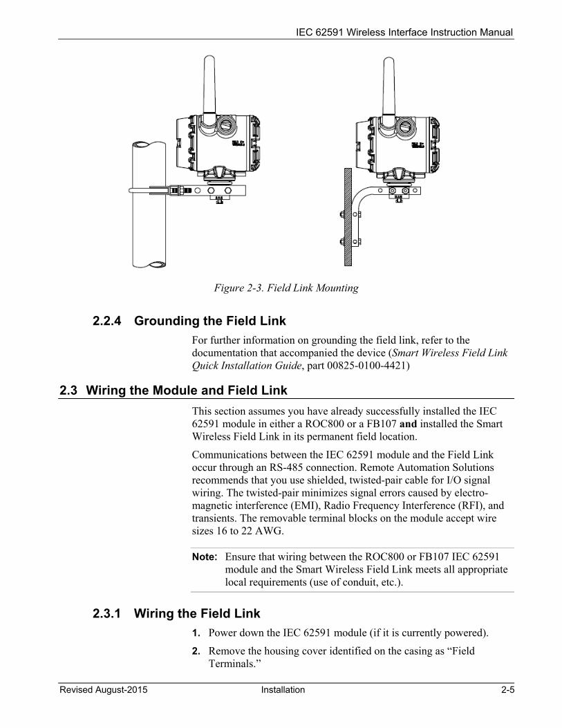
2.2.3 Mounting the Field Link You typically mount the Field Link on a pipe or mast using the clamps provided in the kit (see Figure 2-3).
1. Attach the L-shaped bracket to the pipe or mast.
For pipe installations, insert the larger U-bolt around the 2-in. pipe, through the L-shaped bracket, and through the washer plate (see the left side of Figure 2-3). Use a ½-in. socket-head wrench to secure the nuts to the U-bolt.
For mast installations, bolt the L-shaped bracket securely to the mast (see the right side of Figure 2-3).
2. Insert the smaller U-bolt around the base of the Field Link and through the L-shaped bracket.
3. Use a ½-in. socket-head wrench to fasten the nuts to the U-bolt.
IEC 62591 Wireless Interface Instruction Manual
Revised August-2015 Installation 2-5
Figure 2-3. Field Link Mounting
2.2.4 Grounding the Field Link For further information on grounding the field link, refer to the documentation that accompanied the device (Smart Wireless Field Link Quick Installation Guide, part 00825-0100-4421)
2.3 Wiring the Module and Field Link This section assumes you have already successfully installed the IEC 62591 module in either a ROC800 or a FB107 and installed the Smart Wireless Field Link in its permanent field location.
Communications between the IEC 62591 module and the Field Link occur through an RS-485 connection. Remote Automation Solutions recommends that you use shielded, twisted-pair cable for I/O signal wiring. The twisted-pair minimizes signal errors caused by electro-magnetic interference (EMI), Radio Frequency Interference (RFI), and transients. The removable terminal blocks on the module accept wire sizes 16 to 22 AWG.
Note: Ensure that wiring between the ROC800 or FB107 IEC 62591 module and the Smart Wireless Field Link meets all appropriate local requirements (use of conduit, etc.).
2.3.1 Wiring the Field Link 1. Power down the IEC 62591 module (if it is currently powered).
2. Remove the housing cover identified on the casing as “Field Terminals.”
IEC 62591 Wireless Interface Instruction Manual
2-6 Installation Revised August-2015
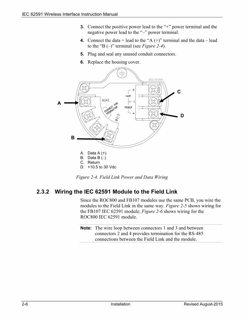
3. Connect the positive power lead to the “+” power terminal and the negative power lead to the “–” power terminal.
4. Connect the data + lead to the “A (+)” terminal and the data – lead to the “B (–)” terminal (see Figure 2-4).
5. Plug and seal any unused conduit connectors.
6. Replace the housing cover.
A. Data A (+) B. Data B (–) C. Return D. +10.5 to 30 Vdc
Figure 2-4. Field Link Power and Data Wiring
2.3.2 Wiring the IEC 62591 Module to the Field Link Since the ROC800 and FB107 modules use the same PCB, you wire the modules to the Field Link in the same way. Figure 2-5 shows wiring for the FB107 IEC 62591 module; Figure 2-6 shows wiring for the ROC800 IEC 62591 module.
Note: The wire loop between connectors 1 and 3 and between connectors 2 and 4 provides termination for the RS-485 connections between the Field Link and the module.
A
B
C
D

IEC 62591 Wireless Interface Instruction Manual
Revised August-2015 Installation 2-7
Figure 2-5. FB107 IEC 62591 Module Power and Data Wiring to Field Link
Figure 2-6. ROC800 IEC 62591 Module Power and Data Wiring to Field Link
2.4 Preparing for Configuration and Commissioning Once you have completed the wiring between the Field Link and the ROC800 or FB107, re-attach the wire covers (on the ROC800) and apply power to the ROC800 or FB107.
Proceed to Chapter 3.

IEC 62591 Wireless Interface Instruction Manual
2-8 Installation Revised August-2015
[This page is intentionally left blank.]
IEC 62591 Wireless Interface Instruction Manual
Revised August-2015 Configuration and Commissioning 3-1
Chapter 3 – Configuration and Commissioning
In This Chapter
3.1 Overview .......................................................................................... 3-2 3.1.1 Configuring Devices and Planning the Network ................... 3-2 3.1.2 Network ID and Join Key ...................................................... 3-3 3.1.3 Rosemount THUM™ Adapter ................................................ 3-3
3.2 IEC 62591 Module Interface (FB107) .............................................. 3-3 3.2.1 Commissioning Devices ....................................................... 3-8 3.2.2 Managing Device Information ............................................. 3-10 3.2.3 Reviewing Network Statistics ............................................. 3-14 3.2.4 Retrieving a Diagnostic Log ............................................... 3-14 3.2.5 Displaying Commissioned Transmitters ............................. 3-15 3.2.6 Updating Firmware ............................................................. 3-16
3.3 IEC 62591 Module Interface (ROC800) ........................................ 3-18 3.3.1 Accessing the Network ....................................................... 3-20 3.3.2 Commissioning Devices ..................................................... 3-21 3.3.3 Managing Device Information ............................................. 3-25 3.3.4 Viewing Network Statistics ................................................. 3-28 3.3.5 Retrieving a Diagnostic Log ............................................... 3-29 3.3.6 Updating Firmware ............................................................. 3-30
After you have wired the Field Link to the IEC 62591 module and applied power to the module, you use the AMS Device Configurator to configure transmitters for the wireless network. You then use ROCLINK 800 to activate (or “commission”) each WirelessHART device into the entire network. Both of these software tools are available as part of Field Tools.
Note: Refer to the Emerson Process Management Field Tools Quick Start Guide (part D301703X412) for complete instructions on using AMS Device Configurator to configure the WirelessHART devices with the long tag name, Network ID, and Join Key.
Keep in mind that configuration and commissioning is a two-step process for each device:
1. Configure each device using Field Tools’ AMS Device Configurator and a HART modem (or you can use a hand-held configuration device such as the Emerson 375 or 475 Field Communicator). During this step you individually add network information (Network ID, Join Key, and long tag name) to the field- based wireless device.
2. Use ROCLINK 800 to configure the network by commissioning the device as a working part of the network.
Note: The commissioning process assumes that you have already placed and powered up a number of WirelessHART devices in the field.

IEC 62591 Wireless Interface Instruction Manual
3-2 Configuration and Commissioning Revised August-2015
3.1 Overview As indicated previously, a wireless interface network consists of a number of wireless devices (up to 60 in a ROC800-based network or up to 20 in an FB107-based network), a Smart Wireless Field Link, and an IEC 62591 module installed in an FB107 or ROC800. For the configuration and commissioning tasks described in this chapter, we’ve added a PC running ROCLINK 800 to Figure 3-1.
Figure 3-1. Wireless Interface (ROC800-based)
3.1.1 Configuring Devices and Planning the Network Before you can use a WirelessHART device, you must first configure it. For this task (which is outside the scope of this manual) you may use a hand-held field communicator (such as Emerson’s 375 or 475 Field Communicator) or Field Tools’ AMS Device Configurator. Ideally, you configure individual devices at a workbench in a protected environment, although you can field-configure a device you might add to the network. During the configuration, you identify the Network ID to which the device eventually belongs and provide the network-specific Join Key (see Network ID and Join Key).
During configuration, you also give the wireless device a 32-character tag based on its use or location (such as PUMP1TEMPORARY, PUMP2WESTPRESSURE, or WELL02NORTHLEVEL). The serial number for the device provides further identifiers the configuration software uses. We also suggest you use all capital letters for the tags, which correlates to the way the system stores this information.
Notes: Tag names cannot exceed 32 characters, and tag names must be
unique to the wireless network. Use upper-case (capital) letters for tags names; this corresponds to
how the program internally stores tag names.

IEC 62591 Wireless Interface Instruction Manual
Revised August-2015 Configuration and Commissioning 3-3
The individual devices should fit into a general organizational plan for your fields. By identifying logical groups and pre-assigning devices to those groups, you can eliminate guesswork during commissioning, efficiently define networks, and more quickly begin to acquire data.
Note: An important restriction in planning networks is to know that a network can have only one Network ID, one Join Key, one Field Link, and one controller (a ROC800 supporting up to 60 devices or a FB107 supporting up to 20 devices).
3.1.2 Network ID and Join Key A Network ID defines one logical grouping of WirelessHART devices, all of which send their information to one Field Link. (You define a device’s Network ID when you first configure the device with a 375 Field Communicator or Field Tools’ HART Device Configurator.)
Note: A Network ID cannot be all zeros (such as 00000).
The Join Key is the password that allows a device to access its defined network. During configuration, you also provide the device with its network-specific Join Key. During configuration and commissioning, ROCLINK 800 uses the Network ID and Join Key to create the network (see Figure 3-3).
3.1.3 Rosemount THUM™ Adapter Note: Each THUM adapter supports only one wired HART device.
Rosemount’s THUM™ Adapter provides wireless connectivity to a wired HART device. If you have already commissioned a wired HART device into your network and want to connect it to a THUM Adapter, you must first decommission the device, attach the THUM Adapter, and then re-commission the device. For further information about THUM Adapters, refer to:
Smart Wireless THUM™ Adapter Reference Manual, 00809-0100-4075, Rev CA, March 2014
Smart Wireless THUM™ Adapter Quick Installation Guide, 00825-0100-4075, Rev DA, July 2011.
The Quick Installation Guide was packed in the box with the THUM; the Reference Manual is available on the Rosemount website (www.EmersonProcess.com/Rosemount).
3.2 IEC 62591 Module Interface (FB107) The FB107 automatically recognizes the IEC62691 module when you install it and adds it to the graphical interface. When you click on the module, ROCLINK 800 displays the main IEC 62591 screen below the image of the FB107:
IEC 62591 Wireless Interface Instruction Manual
3-4 Configuration and Commissioning Revised August-2015
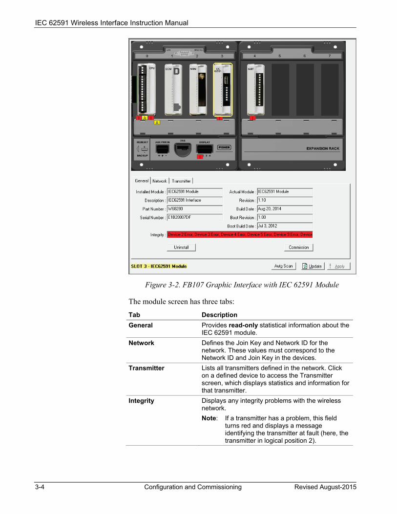
Figure 3-2. FB107 Graphic Interface with IEC 62591 Module
The module screen has three tabs:
Tab Description General Provides read-only statistical information about the
IEC 62591 module. Network Defines the Join Key and Network ID for the
network. These values must correspond to the Network ID and Join Key in the devices.
Transmitter Lists all transmitters defined in the network. Click on a defined device to access the Transmitter screen, which displays statistics and information for that transmitter.
Integrity Displays any integrity problems with the wireless network. Note: If a transmitter has a problem, this field
turns red and displays a message identifying the transmitter at fault (here, the transmitter in logical position 2).
IEC 62591 Wireless Interface Instruction Manual
Revised August-2015 Configuration and Commissioning 3-5
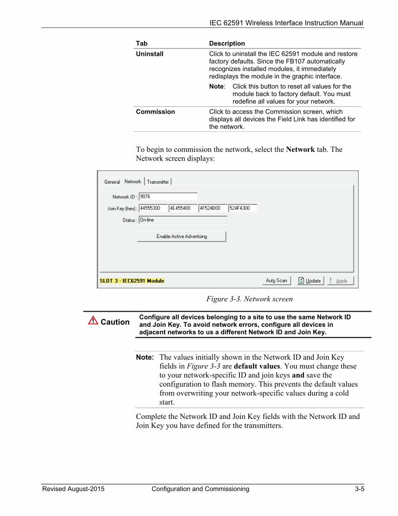
Tab Description Uninstall Click to uninstall the IEC 62591 module and restore
factory defaults. Since the FB107 automatically recognizes installed modules, it immediately redisplays the module in the graphic interface. Note: Click this button to reset all values for the
module back to factory default. You must redefine all values for your network.
Commission Click to access the Commission screen, which displays all devices the Field Link has identified for the network.
To begin to commission the network, select the Network tab. The Network screen displays:
Figure 3-3. Network screen
Caution Configure all devices belonging to a site to use the same Network ID and Join Key. To avoid network errors, configure all devices in adjacent networks to us a different Network ID and Join Key.
Note: The values initially shown in the Network ID and Join Key fields in Figure 3-3 are default values. You must change these to your network-specific ID and join keys and save the configuration to flash memory. This prevents the default values from overwriting your network-specific values during a cold start.
Complete the Network ID and Join Key fields with the Network ID and Join Key you have defined for the transmitters.
IEC 62591 Wireless Interface Instruction Manual
3-6 Configuration and Commissioning Revised August-2015
Field Description Network ID Enter a five-character Network ID. Valid values are
1 to 36863. Should be noted that each IEC62591 Module / RTU can only have a single Network ID. The "grouping" should be related to the control/monitoring network for a given RTU. For example if two RTUs are installed at a site, each grouping should be the set of meter runs each RTU controls. Note: A Network ID cannot be all zeros (such as 00000).
Join Key (hex) Enter a valid Join Key to permit the device to access its defined network. A Join Key is a 128-byte value expressed as four 32-bit portions. As shown in the example, you can use zeros for the first three parts of the Join Key.
Status This read-only field shows the current status of the connection between the network and ROCLINK 800.
Enable Active Advertising
Click to enable active advertising, in which the IEC 62591 module continuously broadcasts network information. This enables new devices to quickly join the network. Active advertising broadcasts network information continuously for approximately 30 minutes. Additionally, active advertising occurs automatically when: You first power up or restart the IEC 62591
module; or A device leaves the network (which allows
communications to re-establish).
Click Apply. As the Field Link processes your request to add the device to the network, the value displayed in the Status field changes:
Initializing. The module is in the boot-up sequence. The module sends info (Part Number, firmware version, etc.) to the RTU. During this time, the module is not yet communicating with the RTU. Once the code starts up (usually after 30-60 seconds), the module switches from Initializing to Configuring Network.
Configuring Network. The code is running and the module is attempting to pull configuration info from the RTU. If the Initializing status is taking too long, it means that either
the board is not completely booting up, or
the application code is not correctly loading. As a result, the sequence cannot complete.
Detecting radio. The Field Link recognizes the network.

IEC 62591 Wireless Interface Instruction Manual
Revised August-2015 Configuration and Commissioning 3-7
On-Line. When the Status field shows On-line, you can begin commissioning devices for the network.
Select the General tab, and click Commission. The IEC 62591 Module screen displays.
Figure 3-4. IEC 62591Module
The screen has four tabs:
Tab Description Commission Auto-detects available uncommissioned devices
and enables you to add them to the defined network.
Transmitter Accesses both read-only statistics and modifiable parameters for a specific device associated with the network. Note: You must first commission a device before
you can access this tab. Statistics Provides read-only statistics the Field Link has
accumulated for the network. Click Reset Statistics to reset these values at any time.
Diagnostics Describes how to use the module’s USB port to generate log information for resolving issues.
The following sections discuss how to use these tabs to manage your network.

IEC 62591 Wireless Interface Instruction Manual
3-8 Configuration and Commissioning Revised August-2015
3.2.1 Commissioning Devices You use the Commission tab to individually or collectively commission devices.
Figure 3-5. Commission tab
This screen has two lists, Uncommissioned and Commissioned. When the Status field on the Network screen displays On-line, the Field Link automatically begins adding devices to the Uncommissioned list. To commission a device, you move it to the Commissioned list in either of two ways:
Select the device and click Commission. ROCLINK 800 places the device in the first available empty row on the Commissioned list.
Notes: To select several devices, press Ctrl and left-click each
additional device. Click Commission when you have finished selecting devices.
When commissioning a HART device connected to a Smart Wireless THUM™ Adapter, the system detects both the HART device and the THUM Adapter and places them both in the Uncommissioned list. Commission the device as normal. Commission the THUM Adapter only if you need the Adapter’s process data.
IEC 62591 Wireless Interface Instruction Manual
Revised August-2015 Configuration and Commissioning 3-9
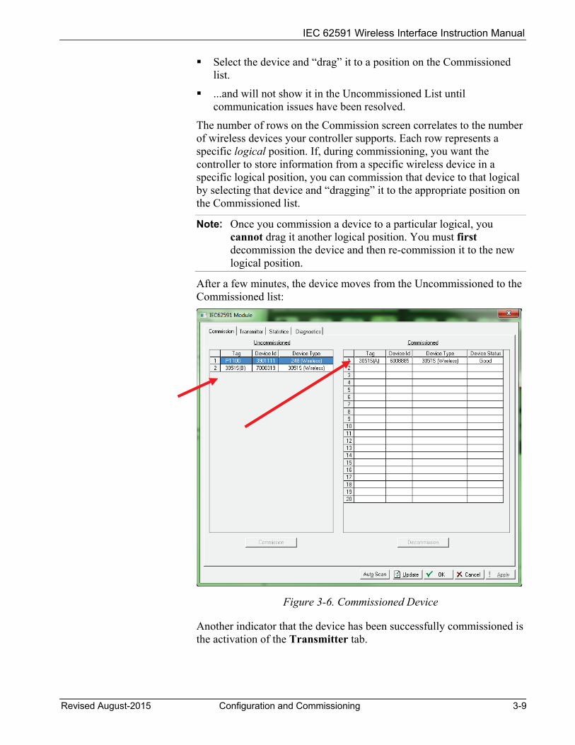
Select the device and “drag” it to a position on the Commissioned list.
...and will not show it in the Uncommissioned List until communication issues have been resolved.
The number of rows on the Commission screen correlates to the number of wireless devices your controller supports. Each row represents a specific logical position. If, during commissioning, you want the controller to store information from a specific wireless device in a specific logical position, you can commission that device to that logical by selecting that device and “dragging” it to the appropriate position on the Commissioned list.
Note: Once you commission a device to a particular logical, you cannot drag it another logical position. You must first decommission the device and then re-commission it to the new logical position.
After a few minutes, the device moves from the Uncommissioned to the Commissioned list:
Figure 3-6. Commissioned Device
Another indicator that the device has been successfully commissioned is the activation of the Transmitter tab.

IEC 62591 Wireless Interface Instruction Manual
3-10 Configuration and Commissioning Revised August-2015
Note: If you change the tag for a transmitter using either a hand-held 375/475 device or AMS, the new tag may not display until the device appears on the Commissioned list.
Decommissioning a Device If you decide to remove a device from your network, use this screen to decommission the device. Select the device and drag it to the Uncommissioned list.
Note: Remember to adjust or redefine any TLPs you have designated to accumulate the information for the decommissioned device’s logical position.
Replacing a Device If a particular wireless device in your network stops working, you can easily replace it with a similar device.
Note: Using this option does not require you to adjust or redefine any TLPs you have designated to accumulate the information for the decommissioned device’s logical position. The new device assumes all parameters you have defined for the old device.
First, configure the device for the network, assigning it the appropriate Network ID and Join Key. Install the device in the field. Start ROCLINK 800, select the IEC 62591 module, and display the Commission tab. When the replacement device appears on the Uncommissioned list, select it and drag it on top of the non-working device. This tells ROCLINK 800 that you want this new device to assume all the defined characteristics of the old device.
ROCLINK 800 displays a verification dialog to prevent you from accidentally replacing a device:
Figure 3-7. Device Replacement Verification Dialog
Click Yes to complete the replacement. ROCLINK commissions the new device and automatically decommissions the old device, moving it to the Uncommissioned list.
3.2.2 Managing Device Information Once you have commissioned a device, the Transmitter tab can provide you with a variety of information on that device. Select the Transmitter tab to display the Transmitter screen:
IEC 62591 Wireless Interface Instruction Manual
Revised August-2015 Configuration and Commissioning 3-11
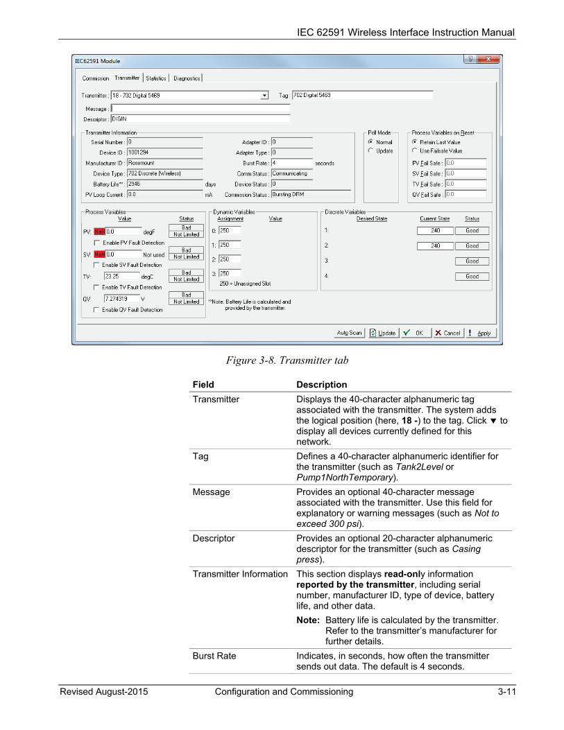
Figure 3-8. Transmitter tab
Field Description Transmitter Displays the 40-character alphanumeric tag
associated with the transmitter. The system adds the logical position (here, 18 -) to the tag. Click to display all devices currently defined for this network.
Tag Defines a 40-character alphanumeric identifier for the transmitter (such as Tank2Level or Pump1NorthTemporary).
Message Provides an optional 40-character message associated with the transmitter. Use this field for explanatory or warning messages (such as Not to exceed 300 psi).
Descriptor Provides an optional 20-character alphanumeric descriptor for the transmitter (such as Casing press).
Transmitter Information This section displays read-only information reported by the transmitter, including serial number, manufacturer ID, type of device, battery life, and other data. Note: Battery life is calculated by the transmitter.
Refer to the transmitter’s manufacturer for further details.
Burst Rate Indicates, in seconds, how often the transmitter sends out data. The default is 4 seconds.
IEC 62591 Wireless Interface Instruction Manual
3-12 Configuration and Commissioning Revised August-2015
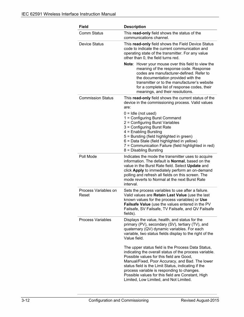
Field Description Comm Status This read-only field shows the status of the
communications channel. Device Status This read-only field shows the Field Device Status
code to indicate the current communication and operating state of the transmitter. For any value other than 0, the field turns red. Note: Hover your mouse over this field to view the
meaning of the response code. Response codes are manufacturer-defined. Refer to the documentation provided with the transmitter or to the manufacturer’s website for a complete list of response codes, their meanings, and their resolutions.
Commission Status This read-only field shows the current status of the device in the commissioning process. Valid values are: 0 = Idle (not used) 1 = Configuring Burst Command 2 = Configuring Burst Variables 3 = Configuring Burst Rate 4 = Enabling Bursting 5 = Bursting (field highlighted in green) 6 = Data Stale (field highlighted in yellow) 7 = Communication Failure (field highlighted in red) 8 = Disabling Bursting
Poll Mode Indicates the mode the transmitter uses to acquire information. The default is Normal, based on the value in the Burst Rate field. Select Update and click Apply to immediately perform an on-demand polling and refresh all fields on this screen. The mode reverts to Normal at the next Burst Rate interval.
Process Variables on Reset
Sets the process variables to use after a failure. Valid values are Retain Last Value (use the last known values for the process variables) or Use Failsafe Value (use the values entered in the PV Failsafe, SV Failsafe, TV Failsafe, and QV Failsafe fields).
Process Variables Displays the value, health, and status for the primary (PV), secondary (SV), tertiary (TV), and quaternary (QV) dynamic variables. For each variable, two status fields display to the right of the Value field. The upper status field is the Process Data Status, indicating the overall status of the process variable. Possible values for this field are Good, Manual/Fixed, Poor Accuracy, and Bad. The lower status field is the Limit Status, indicating if the process variable is responding to changes. Possible values for this field are Constant, High Limited, Low Limited, and Not Limited.

IEC 62591 Wireless Interface Instruction Manual
Revised August-2015 Configuration and Commissioning 3-13
Field Description The module returns four additional bits, but these are not displayed through ROCLINK. Bit 3 indicates the More Device Variable Status Available. Bits 2 through 0 indicate the Device Family Specific Status. Use TLPs to retrieve these additional bits for the PV Status (177,x,60), SV Status (177,x,61), TV Status (177,x,62), and QV Status (177,x,63). For more information, refer to the Command Summary Specification (HCF_SPEC-99), available from the HART Communication Foundation.
Enable Fault Detection Check to enable fault detection on the process variables. If enabled and the system detects a fault, the system marks the field in red and displays NaN (not a number). Note: You enable fault detection individually for each process variable. This field applies only to the FB107.
Dynamic Variables Defines the slot assignment and associated value for up to four slot-based variables. Each wireless transmitter contains up to 250 slots able to store variable information (such as temperature, pressure, scaling factors, altitude, flow, and so on). Each transmitter manufacturer defines which slots contain what information. Refer to the documentation provided with the transmitter or to the manufacturer’s website for a complete list of slot assignments. Note: WirelessHART conventions require that all
manufacturers reserve slots 246 through 249 for the dynamic variables PV, SV, TV, and FV, respectively. Slot 250 is also reserved as permanently unassigned, and does not accumulate values.
Discrete Variables Sets the configuration and shows the status of connected discrete devices that support discrete variables. The IEC 62591 module can control a maximum of four discrete variables that display in a list in the Discrete Variables field. Refer to the documentation for your specific discrete device for a list of available set points and possible statuses. An example of a discrete device that supports discrete variables is a discrete valve. You can configure the set point of the discrete valve as being Open or Closed. These set points are shown as radio buttons in the Discrete Variables list. The status of the device in relation to the configured set point is displayed in the Discrete Variables list to the left of the set point. In the discrete valve example, the status might show Closed, Open, Closing, or Opening. Note: Click Update to manually refresh the Status field.

IEC 62591 Wireless Interface Instruction Manual
3-14 Configuration and Commissioning Revised August-2015
Click Apply to save any changes you may make to the values on this screen.
Note: You can also double-click a commissioned device on the Commission screen to immediately access the Transmitter screen for that device.
3.2.3 Reviewing Network Statistics Select the Statistics tab to display the Statistics screen:
Figure 3-9. Statistics screen
This screen displays accumulated read-only statistics about the network. Click Reset Statistics at any time to zero-out all accumulated values.
3.2.4 Retrieving a Diagnostic Log The IEC 62591 module has a USB port which you can use to retrieve a diagnostic log to assist in troubleshooting. Select the Diagnostics tab to display the Diagnostics screen:
IEC 62591 Wireless Interface Instruction Manual
Revised August-2015 Configuration and Commissioning 3-15
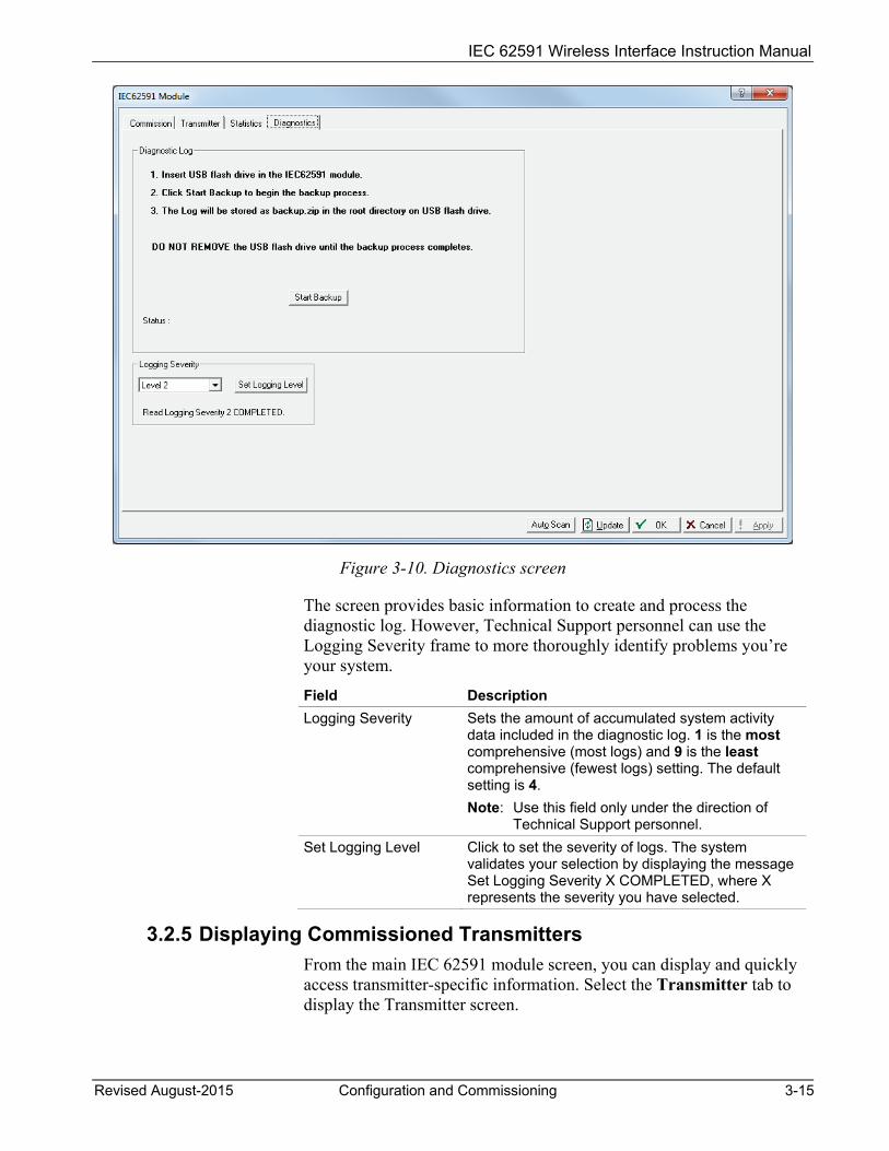
Figure 3-10. Diagnostics screen
The screen provides basic information to create and process the diagnostic log. However, Technical Support personnel can use the Logging Severity frame to more thoroughly identify problems you’re your system.
Field Description Logging Severity Sets the amount of accumulated system activity
data included in the diagnostic log. 1 is the most comprehensive (most logs) and 9 is the least comprehensive (fewest logs) setting. The default setting is 4. Note: Use this field only under the direction of
Technical Support personnel. Set Logging Level Click to set the severity of logs. The system
validates your selection by displaying the message Set Logging Severity X COMPLETED, where X represents the severity you have selected.
3.2.5 Displaying Commissioned Transmitters From the main IEC 62591 module screen, you can display and quickly access transmitter-specific information. Select the Transmitter tab to display the Transmitter screen.
IEC 62591 Wireless Interface Instruction Manual
3-16 Configuration and Commissioning Revised August-2015
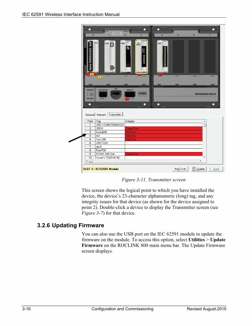
Figure 3-11. Transmitter screen
This screen shows the logical point to which you have installed the device, the device’s 23-character alphanumeric (long) tag, and any integrity issues for that device (as shown for the device assigned to point 2). Double-click a device to display the Transmitter screen (see Figure 3-7) for that device.
3.2.6 Updating Firmware You can also use the USB port on the IEC 62591 module to update the firmware on the module. To access this option, select Utilities > Update Firmware on the ROCLINK 800 main menu bar. The Update Firmware screen displays.
IEC 62591 Wireless Interface Instruction Manual
Revised August-2015 Configuration and Commissioning 3-17
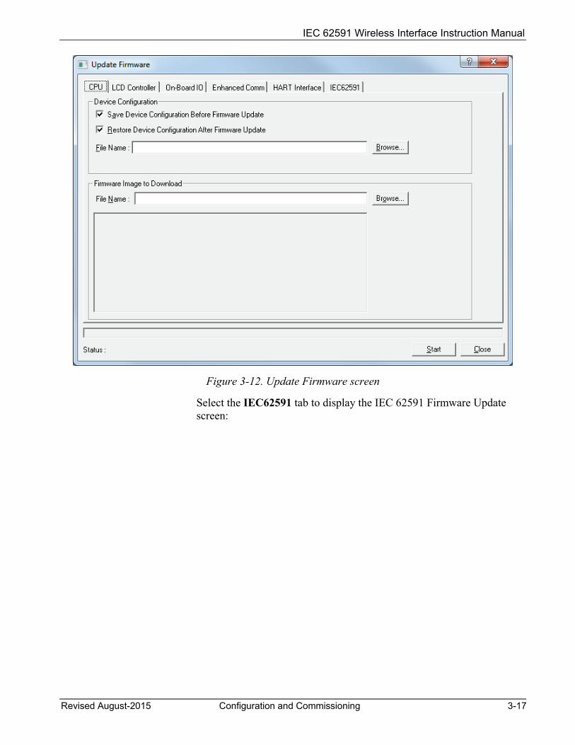
Figure 3-12. Update Firmware screen
Select the IEC62591 tab to display the IEC 62591 Firmware Update screen:
IEC 62591 Wireless Interface Instruction Manual
3-18 Configuration and Commissioning Revised August-2015
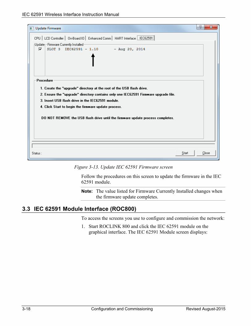
Figure 3-13. Update IEC 62591 Firmware screen
Follow the procedures on this screen to update the firmware in the IEC 62591 module.
Note: The value listed for Firmware Currently Installed changes when the firmware update completes.
3.3 IEC 62591 Module Interface (ROC800) To access the screens you use to configure and commission the network:
1. Start ROCLINK 800 and click the IEC 62591 module on the graphical interface. The IEC 62591 Module screen displays:
IEC 62591 Wireless Interface Instruction Manual
Revised August-2015 Configuration and Commissioning 3-19
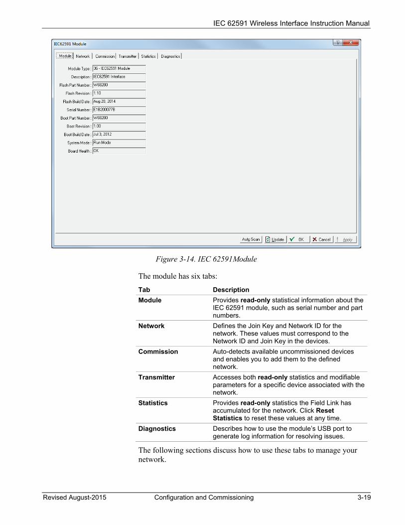
Figure 3-14. IEC 62591Module
The module has six tabs:
Tab Description Module Provides read-only statistical information about the
IEC 62591 module, such as serial number and part numbers.
Network Defines the Join Key and Network ID for the network. These values must correspond to the Network ID and Join Key in the devices.
Commission Auto-detects available uncommissioned devices and enables you to add them to the defined network.
Transmitter Accesses both read-only statistics and modifiable parameters for a specific device associated with the network.
Statistics Provides read-only statistics the Field Link has accumulated for the network. Click Reset Statistics to reset these values at any time.
Diagnostics Describes how to use the module’s USB port to generate log information for resolving issues.
The following sections discuss how to use these tabs to manage your network.

IEC 62591 Wireless Interface Instruction Manual
3-20 Configuration and Commissioning Revised August-2015
3.3.1 Accessing the Network Use this screen to identify the Network ID and Join Key for the devices in your network. When you select the Network tab, you must complete two fields:
Figure 3-15. Network tab
Field Description Network ID Enter a five-character Network ID. Valid values are
1 to 36863. Should be noted that each IEC62591 Module / RTU can only have a single Network ID. The "grouping" should be related to the control/monitoring network for a given RTU. For example if two RTUs are installed at a site, each grouping should be the set of meter runs each RTU controls. Note: A Network ID cannot be all zeros (such as 00000).
Join Key (hex) Enter a valid Join Key to permit the device to access its defined network. A Join Key is a 128-byte value expressed as four 32-bit portions. As shown in the example, you can use zeros for the first three parts of the Join Key.

IEC 62591 Wireless Interface Instruction Manual
Revised August-2015 Configuration and Commissioning 3-21
Field Description Status This read-only field shows the current status of the
connection between the network and ROCLINK 800.
Enable Active Advertising
Click to enable active advertising, in which the IEC 62591 module continuously broadcasts network information. This enables new devices to quickly join the network. Active advertising broadcasts network information continuously for approximately 30 minutes. Additionally, active advertising occurs automatically when: You first power up or restart the IEC 62591
module or A device leaves the network (which allows
communications to re-establish).
Click Apply. As the Field Link processes your request to add the device to the network, the value displayed in the Status field changes:
Initializing. The module is in the boot-up sequence. The module sends info (Part Number, firmware version, etc.) to the RTU. During this time, the module is not yet communicating with the RTU. Once the code starts up (usually after 30-60 seconds), the module switches from Initializing to Configuring Network.
Configuring Network. The code is running and the module is attempting to pull configuration info from the RTU. If the Initializing status is taking too long, it means that either
the board is not completely booting up, or
the application code is not correctly loading. As a result, the sequence cannot complete.
Detecting radio. The Field Link recognizes the network.
On-Line. When the Status field shows On-line, you can begin commissioning devices for the network.
Proceed to Commissioning Devices.
3.3.2 Commissioning Devices When you select the Commission tab, ROCLINK 800 displays the Commission screen (see Figure 3-16). You use this screen to individually or collectively commission devices.
IEC 62591 Wireless Interface Instruction Manual
3-22 Configuration and Commissioning Revised August-2015
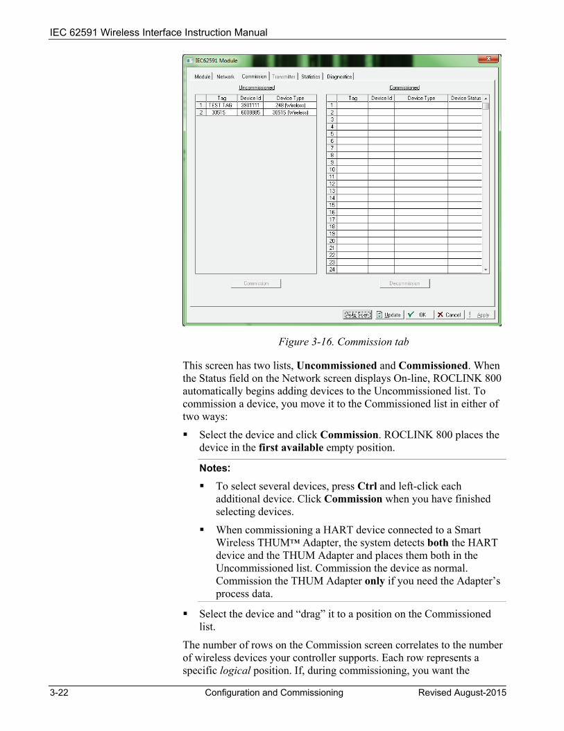
Figure 3-16. Commission tab
This screen has two lists, Uncommissioned and Commissioned. When the Status field on the Network screen displays On-line, ROCLINK 800 automatically begins adding devices to the Uncommissioned list. To commission a device, you move it to the Commissioned list in either of two ways:
Select the device and click Commission. ROCLINK 800 places the device in the first available empty position.
Notes: To select several devices, press Ctrl and left-click each
additional device. Click Commission when you have finished selecting devices.
When commissioning a HART device connected to a Smart Wireless THUM™ Adapter, the system detects both the HART device and the THUM Adapter and places them both in the Uncommissioned list. Commission the device as normal. Commission the THUM Adapter only if you need the Adapter’s process data.
Select the device and “drag” it to a position on the Commissioned list.
The number of rows on the Commission screen correlates to the number of wireless devices your controller supports. Each row represents a specific logical position. If, during commissioning, you want the
IEC 62591 Wireless Interface Instruction Manual
Revised August-2015 Configuration and Commissioning 3-23
controller to store information from a specific wireless device in a specific logical position, you can commission that device to that logical by selecting that device and “dragging” it to the appropriate position on the Commissioned list.
Note: Once you commission a device to a particular logical, you cannot drag it another logical position. You must first decommission the device and then recommission it to the new logical position.
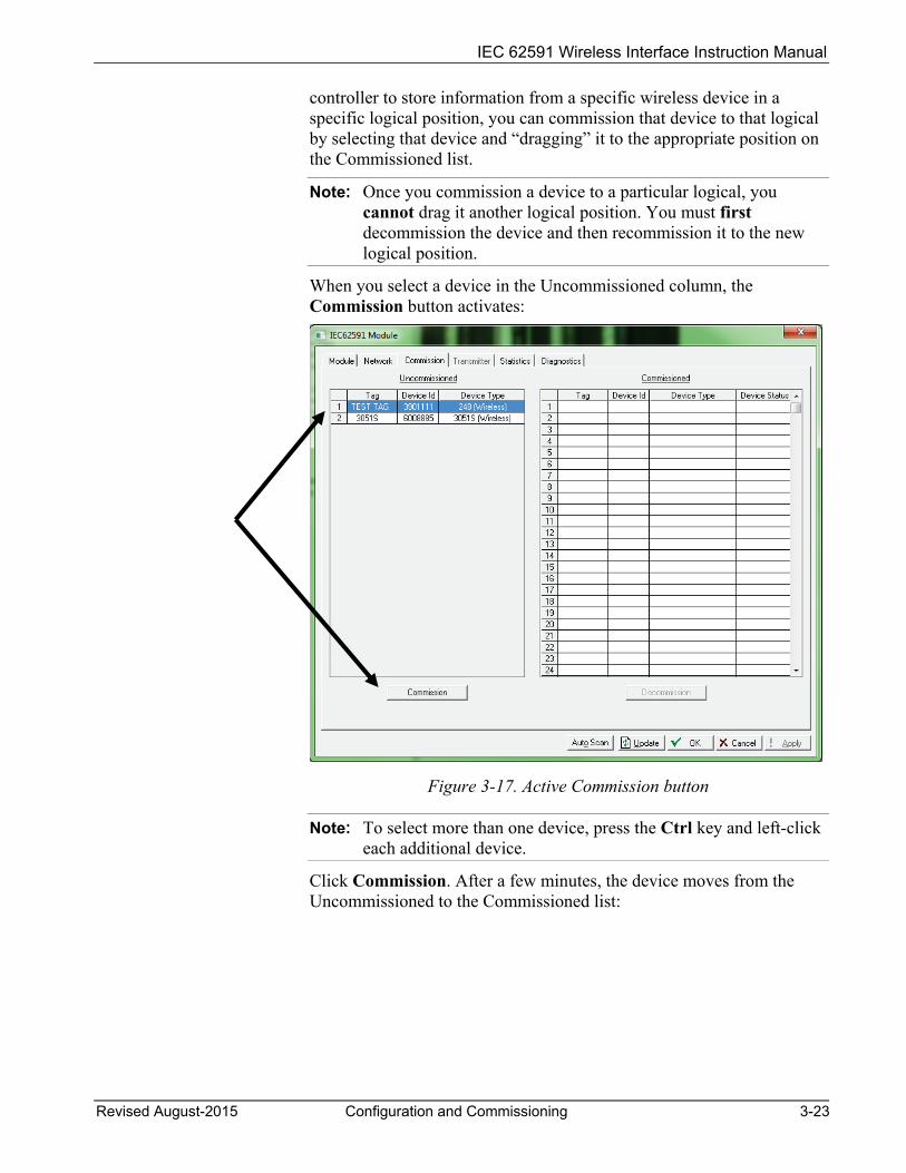
When you select a device in the Uncommissioned column, the Commission button activates:
Figure 3-17. Active Commission button
Note: To select more than one device, press the Ctrl key and left-click each additional device.
Click Commission. After a few minutes, the device moves from the Uncommissioned to the Commissioned list:
IEC 62591 Wireless Interface Instruction Manual
3-24 Configuration and Commissioning Revised August-2015
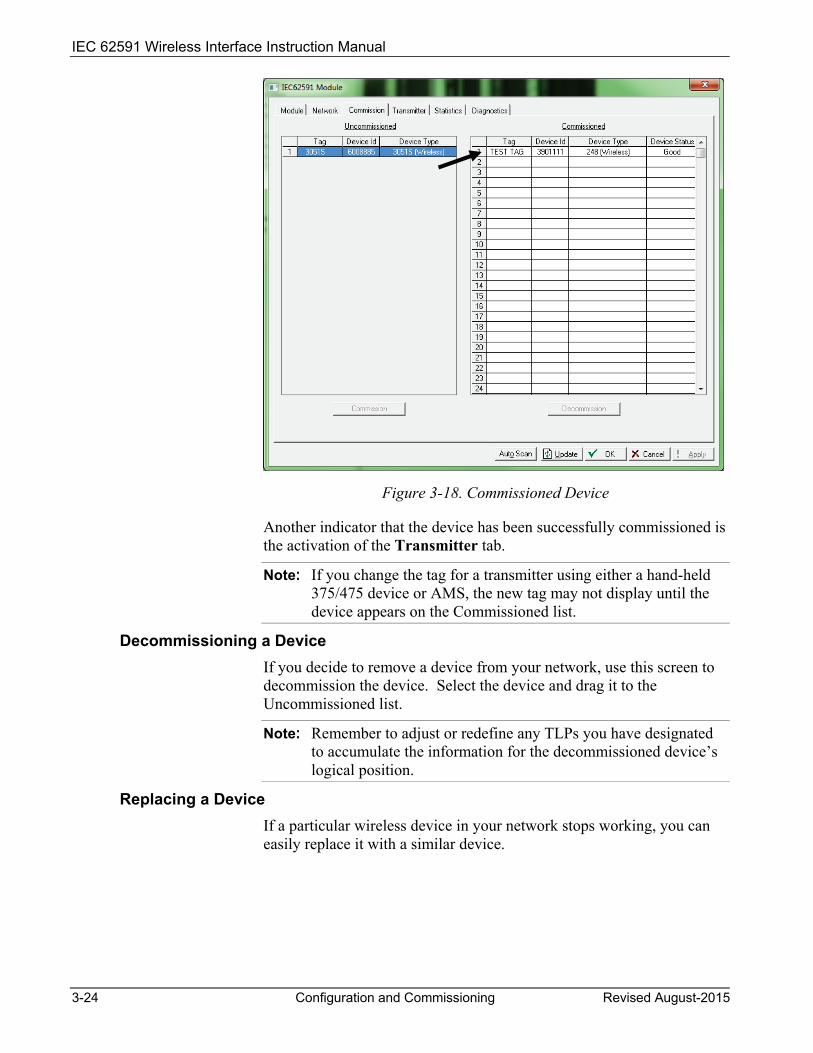
Figure 3-18. Commissioned Device
Another indicator that the device has been successfully commissioned is the activation of the Transmitter tab.
Note: If you change the tag for a transmitter using either a hand-held 375/475 device or AMS, the new tag may not display until the device appears on the Commissioned list.
Decommissioning a Device If you decide to remove a device from your network, use this screen to decommission the device. Select the device and drag it to the Uncommissioned list.
Note: Remember to adjust or redefine any TLPs you have designated to accumulate the information for the decommissioned device’s logical position.
Replacing a Device If a particular wireless device in your network stops working, you can easily replace it with a similar device.
IEC 62591 Wireless Interface Instruction Manual
Revised August-2015 Configuration and Commissioning 3-25
Note: Using this option does not require you to adjust or redefine any TLPs you have designated to accumulate the information for the decommissioned device’s logical position. The new device assumes all parameters you have defined for the old device.
First, configure the device for the network, assigning it the appropriate Network ID and Join Key. Install the device in the field. Start ROCLINK 800, select the IEC 62591 module, and display the Commission tab. When the replacement device appears on the Uncommissioned list, select it and drag it on top of the non-working device. This tells ROCLINK 800 that you want this new device to assume all the defined characteristics of the old device.
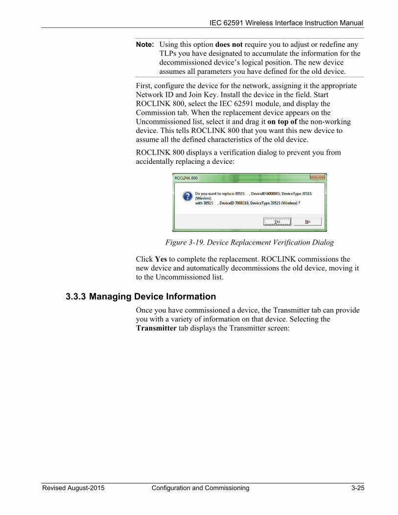
ROCLINK 800 displays a verification dialog to prevent you from accidentally replacing a device:
Figure 3-19. Device Replacement Verification Dialog
Click Yes to complete the replacement. ROCLINK commissions the new device and automatically decommissions the old device, moving it to the Uncommissioned list.
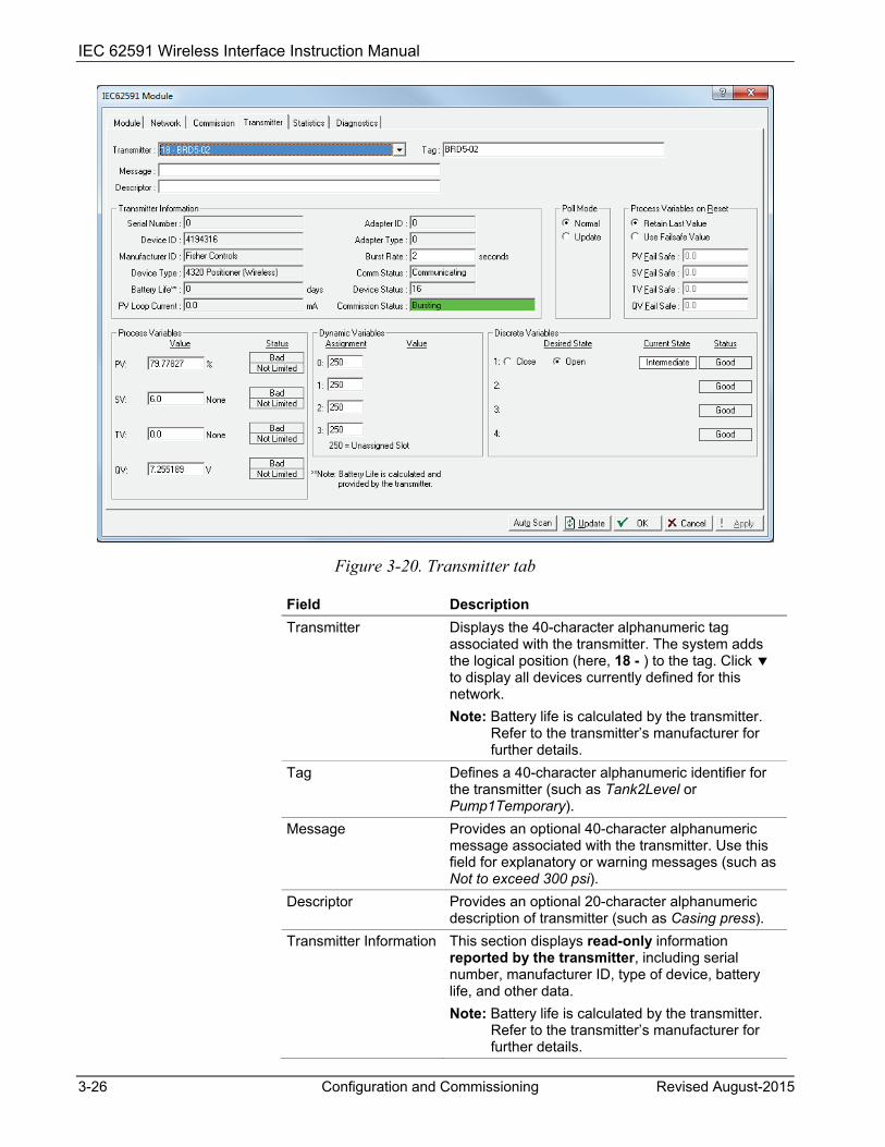
3.3.3 Managing Device Information Once you have commissioned a device, the Transmitter tab can provide you with a variety of information on that device. Selecting the Transmitter tab displays the Transmitter screen:
IEC 62591 Wireless Interface Instruction Manual
3-26 Configuration and Commissioning Revised August-2015
Figure 3-20. Transmitter tab
Field Description Transmitter Displays the 40-character alphanumeric tag
associated with the transmitter. The system adds the logical position (here, 18 - ) to the tag. Click to display all devices currently defined for this network. Note: Battery life is calculated by the transmitter.
Refer to the transmitter’s manufacturer for further details.
Tag Defines a 40-character alphanumeric identifier for the transmitter (such as Tank2Level or Pump1Temporary).
Message Provides an optional 40-character alphanumeric message associated with the transmitter. Use this field for explanatory or warning messages (such as Not to exceed 300 psi).
Descriptor Provides an optional 20-character alphanumeric description of transmitter (such as Casing press).
Transmitter Information This section displays read-only information reported by the transmitter, including serial number, manufacturer ID, type of device, battery life, and other data. Note: Battery life is calculated by the transmitter.
Refer to the transmitter’s manufacturer for further details.

IEC 62591 Wireless Interface Instruction Manual
Revised August-2015 Configuration and Commissioning 3-27
Field Description Burst Rate Indicates, in seconds, how often the transmitter
sends out data. The default is 4 seconds. Comm Status This read-only field shows the status of the
communications channel. Device Status This read-only field shows the Field Device Status
code to indicate the current communication and operating state of the transmitter. For any value other than 0, the field turns red. Note: Hover your mouse over this field to view the
meaning of the response code. Response codes are manufacturer-defined. Refer to the documentation provided with the transmitter or to the manufacturer’s website for a complete list of response codes, their meanings, and their resolutions.
Commission Status Indicates the current status of the device in the commissioning process. Valid values are: 0 = Logical Not Used 1 = Configuring Burst Command 2 = Configuring Burst Variables 3 = Configuring Burst Rate 4 = Enabling Bursting 5 = Bursting (field highlighted in green) 6 = Data Stale (field highlighted in yellow) 7 = Communication Failure (field highlighted in red) 8 = Disabling Bursting
Poll Mode Indicates the mode the transmitter uses to acquire information. The default is Normal, based on the value in the Burst Rate field. Select Update and click Apply to immediately perform an on-demand polling and refresh all fields on this screen. The mode reverts to Normal at the next Burst Rate interval.
Process Variables on Reset
Sets the process variables to use after a failure. Valid values are Retain Last Value (use the last known values for the process variables) or Use Failsafe Value (use the values entered in the PV Failsafe, SV Failsafe, TV Failsafe, and QV Failsafe fields).
Process Variables Displays the values for the primary (PV), secondary (SV), tertiary (TV), and quaternary (QV) process variables.
Dynamic Variables Defines the slot assignment and associated value for up to four slot-based variables. Each wireless transmitter contains up to 250 slots able to store variable information (such as temperature, pressure, scaling factors, altitude, flow, and so on). Each transmitter manufacturer defines which slots contain what information. Refer to the documentation provided with the transmitter or to the manufacturer’s website for a complete list of slot assignments.

IEC 62591 Wireless Interface Instruction Manual
3-28 Configuration and Commissioning Revised August-2015
Field Description Note: WirelessHART conventions require that all
manufacturers reserve slots 246 through 249 for the dynamic variables PV, SV, TV, and FV, respectively. Slot 250 is also reserved as permanently unassigned, and does not accumulate values.
Discrete Variables Sets the configuration and shows the status of connected discrete devices that support discrete variables. The IEC 62591 module can control a maximum of four discrete variables that display in a list in the Discrete Variables field. Refer to the documentation for your specific discrete device for a list of available set points and possible statuses. An example of a discrete device that supports discrete variables is a discrete valve. You can configure the set point of the discrete valve as being Open or Closed. These set points are shown as radio buttons in the Discrete Variables list. The status of the device in relation to the configured set point is displayed in the Discrete Variables list to the left of the set point. In the discrete valve example, the status might show Closed, Open, Closing, or Opening. Note: Click Update to manually refresh the Status field.
Click Apply to save any changes you may make to the values on this screen.
Note: You can also double-click a commissioned device on the Commission screen to immediately access the Transmitter screen for that device.
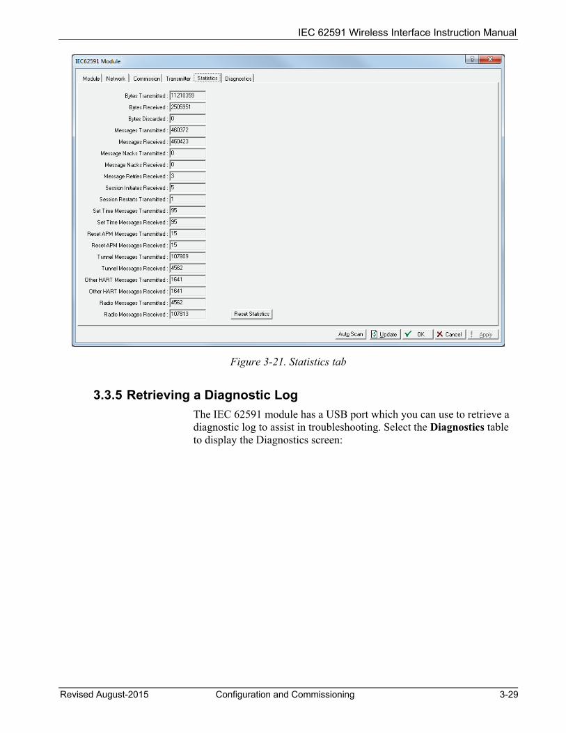
3.3.4 Viewing Network Statistics The network accumulates a variety of statistical information you can review to assess system health. This content displays when you select the Statistics tab:
IEC 62591 Wireless Interface Instruction Manual
Revised August-2015 Configuration and Commissioning 3-29
Figure 3-21. Statistics tab
3.3.5 Retrieving a Diagnostic Log The IEC 62591 module has a USB port which you can use to retrieve a diagnostic log to assist in troubleshooting. Select the Diagnostics table to display the Diagnostics screen:
IEC 62591 Wireless Interface Instruction Manual
3-30 Configuration and Commissioning Revised August-2015
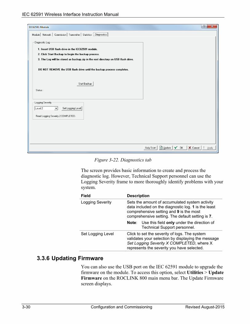
Figure 3-22. Diagnostics tab
The screen provides basic information to create and process the diagnostic log. However, Technical Support personnel can use the Logging Severity frame to more thoroughly identify problems with your system.
Field Description Logging Severity Sets the amount of accumulated system activity
data included on the diagnostic log. 1 is the least comprehensive setting and 9 is the most comprehensive setting. The default setting is 7. Note: Use this field only under the direction of
Technical Support personnel. Set Logging Level Click to set the severity of logs. The system
validates your selection by displaying the message Set Logging Severity X COMPLETED, where X represents the severity you have selected.
3.3.6 Updating Firmware You can also use the USB port on the IEC 62591 module to upgrade the firmware on the module. To access this option, select Utilities > Update Firmware on the ROCLINK 800 main menu bar. The Update Firmware screen displays.
IEC 62591 Wireless Interface Instruction Manual
Revised August-2015 Configuration and Commissioning 3-31
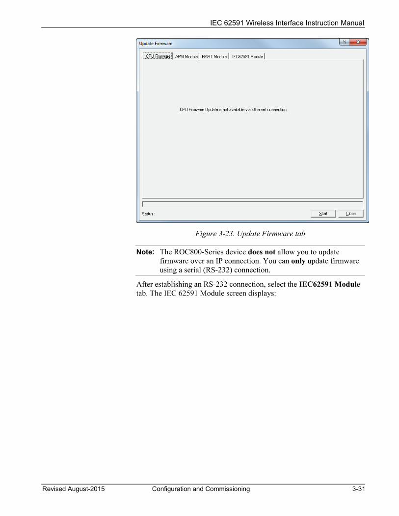
Figure 3-23. Update Firmware tab
Note: The ROC800-Series device does not allow you to update firmware over an IP connection. You can only update firmware using a serial (RS-232) connection.
After establishing an RS-232 connection, select the IEC62591 Module tab. The IEC 62591 Module screen displays:
IEC 62591 Wireless Interface Instruction Manual
3-32 Configuration and Commissioning Revised August-2015
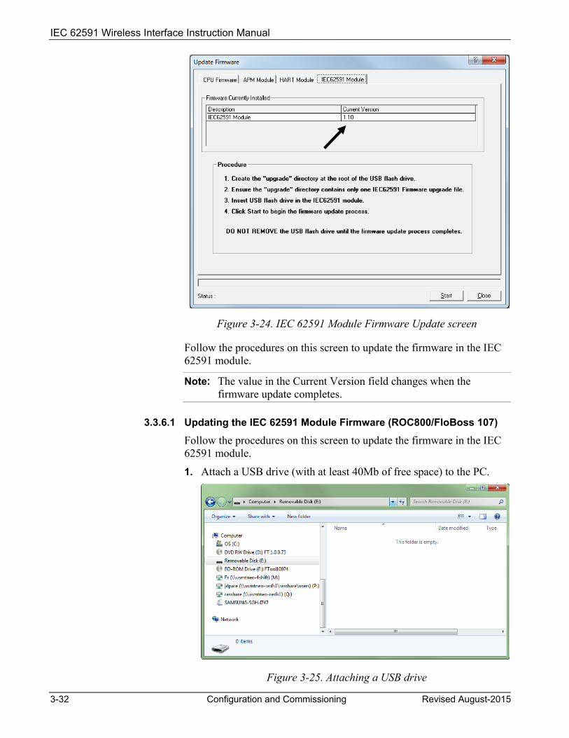
Figure 3-24. IEC 62591 Module Firmware Update screen
Follow the procedures on this screen to update the firmware in the IEC 62591 module.
Note: The value in the Current Version field changes when the firmware update completes.
3.3.6.1 Updating the IEC 62591 Module Firmware (ROC800/FloBoss 107)
Follow the procedures on this screen to update the firmware in the IEC 62591 module.
1. Attach a USB drive (with at least 40Mb of free space) to the PC.
Figure 3-25. Attaching a USB drive
IEC 62591 Wireless Interface Instruction Manual
Revised August-2015 Configuration and Commissioning 3-33
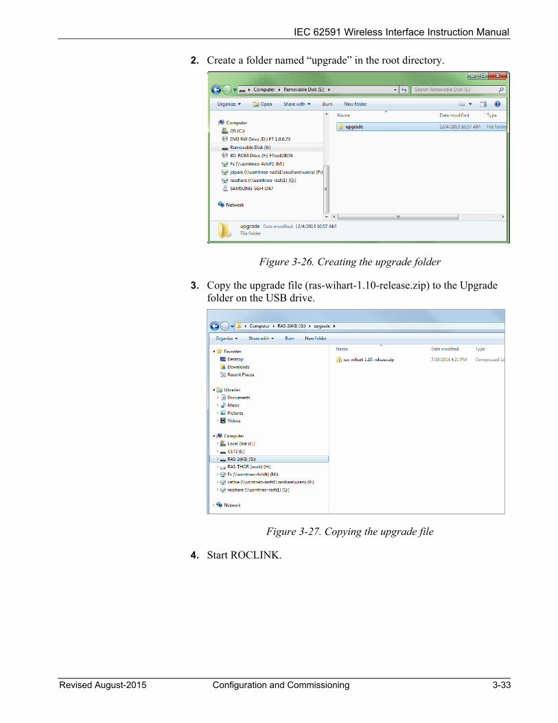
2. Create a folder named “upgrade” in the root directory.
Figure 3-26. Creating the upgrade folder
3. Copy the upgrade file (ras-wihart-1.10-release.zip) to the Upgrade folder on the USB drive.
Figure 3-27. Copying the upgrade file
4. Start ROCLINK.

IEC 62591 Wireless Interface Instruction Manual
3-34 Configuration and Commissioning Revised August-2015
Figure 3-28. Starting ROCLINK
5. Click on the IEC 62591 module to verify that it is running. The System Mode field should contain “Run Mode.”
Figure 3-29. Verifying Run Mode
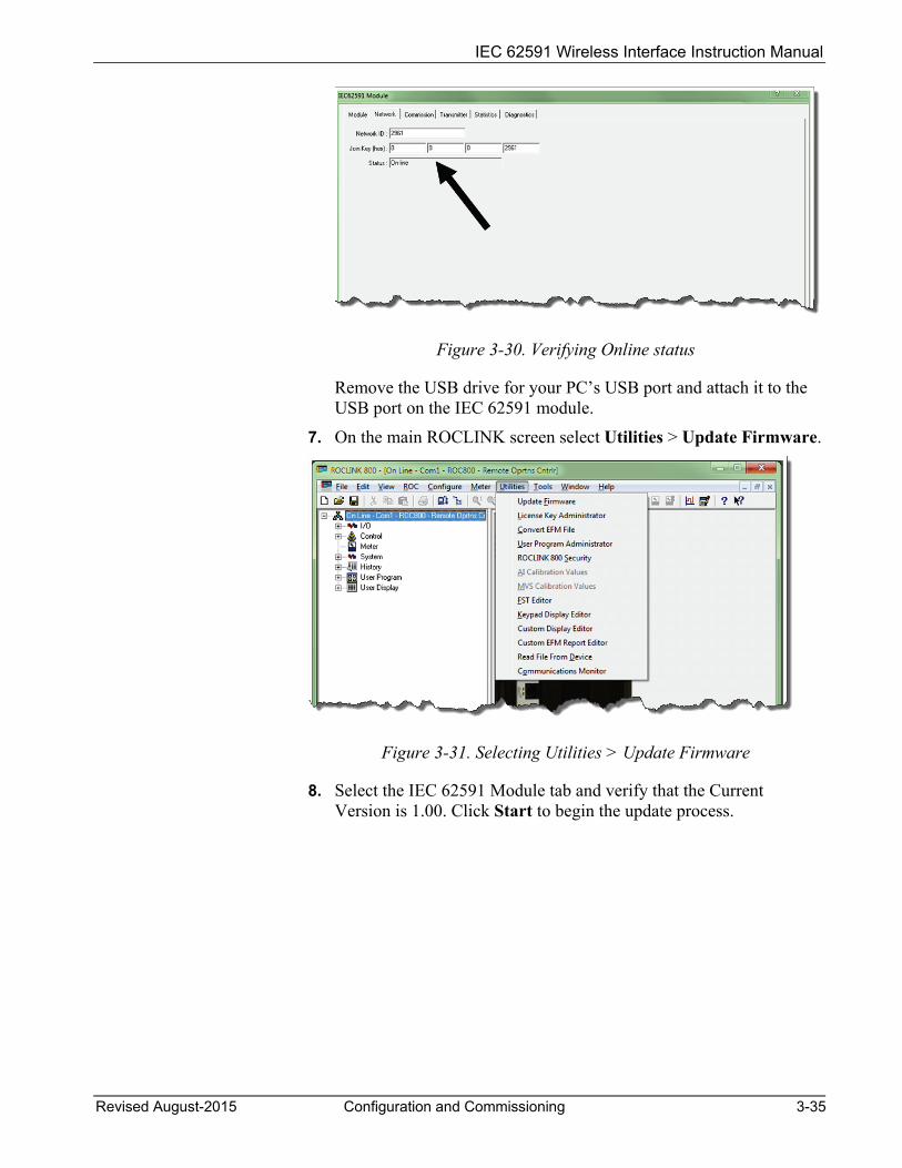
6. Verify that the module is connected to the network and that the module is currently on-line.
IEC 62591 Wireless Interface Instruction Manual
Revised August-2015 Configuration and Commissioning 3-35
Figure 3-30. Verifying Online status
Remove the USB drive for your PC’s USB port and attach it to the USB port on the IEC 62591 module.
7. On the main ROCLINK screen select Utilities > Update Firmware.
Figure 3-31. Selecting Utilities > Update Firmware
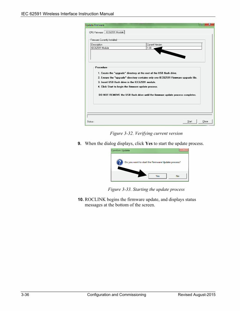
8. Select the IEC 62591 Module tab and verify that the Current Version is 1.00. Click Start to begin the update process.
IEC 62591 Wireless Interface Instruction Manual
3-36 Configuration and Commissioning Revised August-2015
Figure 3-32. Verifying current version
9. When the dialog displays, click Yes to start the update process.
Figure 3-33. Starting the update process
10. ROCLINK begins the firmware update, and displays status messages at the bottom of the screen.

IEC 62591 Wireless Interface Instruction Manual
Revised August-2015 Configuration and Commissioning 3-37
Figure 3-34. Status message: Waiting for upgrade to start
11. Once the update starts, it takes several minutes to complete. Status messages continue to display at the bottom of the screen.
Figure 3-35. Status message: Upgrade in Progress
12. When the update completes, the program reboots the module.

IEC 62591 Wireless Interface Instruction Manual
3-38 Configuration and Commissioning Revised August-2015
Figure 3-36. Status message: Waiting for module to reboot
13. When the firmware update finishes, a dialog displays. Click OK to continue.
Figure 3-37. Firmware update completed dialog box
14. Verify that the version of firmware for the module is now 1.10.
Figure 3-38. Verifying version of upgraded firmware

IEC 62591 Wireless Interface Instruction Manual
Revised August-2015 Configuration and Commissioning 3-39
15. The update process preserves the network settings for your module, but you should still verify that the settings are correct. Click Cancel to close the Update Firmware screen, click on the IEC 62591 module, and select the Network tab to review the network settings.
Figure 3-39. Verifying if settings are still correct
16. The update is complete. Remove the USB drive from the port on the IEC 62591 module.

IEC 62591 Wireless Interface Instruction Manual
3-40 Configuration and Commissioning Revised August-2015
[This page is intentionally left blank.]
IEC62591 Wireless Interface Instruction Manual
Revised August-2015 Troubleshooting 4-1
Chapter 4 – Troubleshooting
In This Chapter
4.1 General Guidelines .......................................................................... 4-1 4.2 Common Troubleshooting Techniques ............................................ 4-2
4.2.1 Identifying which System Components are Working ............ 4-2 4.2.2 Conducting Basic Hardware Checks .................................... 4-2 4.2.3 Looking for Possible Configuration Errors ............................ 4-2 4.2.4 Rebooting after a Power Loss .............................................. 4-3
4.3 Errors from the IEC 62591 Transmitter Tab .................................... 4-3 4.3.1 NaN value ............................................................................. 4-3 4.3.2 Stale / Communication Failure ............................................. 4-4
This chapter provides generalized guidelines for troubleshooting the IEC62591 module and the Smart Wireless Field Link.
4.1 General Guidelines Before you begin to troubleshoot the interface, you should observe the following guidelines:
Don’t overlook the obvious. With all the activity involved in setting up a wireless network, it is easy to accidentally unplug an antenna or disconnect power from a device. Check those things first. (For a list of common problems, see the Troubleshooting Checklist at the end of this chapter.)
If something worked previously but has now stopped working, did you change something? For example, if you re-downloaded the application and now it has stopped working, it’s possible that the change you made to the application might have caused a problem.
Adopt a systematic approach. Don’t try to solve the problem by changing several different things at once. Change one thing, see if it causes an improvement, and make notes about what you did. Then you can try to make other changes. If you haphazardly begin swapping hardware modules, re-routing cables, and changing software parameters, you may end up in worse shape than when you started, or you may end up masking symptoms of an underlying problem.
Try to isolate the problem. For example, if you can communicate with some wireless devices but not others, then concentrate on what’s different with the non-functional wireless devices, or their configuration parameters. If you can’t communicate with any wireless devices, you might not have correctly configured network parameters in the application, or there may be a problem at the field link.
Use the hardware and software diagnostic tools provided with the product. The IEC 62591 wireless application includes error
IEC62591 Wireless Interface Instruction Manual
4-2 Troubleshooting Revised August-2015
codes which you can check; often these will identify configuration problems for you.
Collect and save as much relevant information as you can. If possible, make notes concerning what steps you took leading up to the initial occurrence of the problem. Save printouts, screen captures, error codes, and so on so you can refer to them if you have to call for technical assistance.
4.2 Common Troubleshooting Techniques Common troubleshooting techniques are given below:
4.2.1 Identifying which System Components are Working The wireless interface has several different pieces of hardware and software. A failure in any one of them can cause problems, so you should consider all the different pieces to try to identify the source of your problem. For hardware you have:
FB107/ROC800 controller with IEC 62591 module installed in a slot
Smart Wireless Field Link
PC or laptop connecting the IEC 62591
Cable between IEC 62591 module and Smart Wireless Field Link
One or more wireless devices in the wireless network
Field Communicator (optional)
For software you have:
The IEC 62591 application running in ROCLINK 800
IEC 62591 protocol software running in the Smart Wireless Field Link and in all of the wireless devices
4.2.2 Conducting Basic Hardware Checks Ensure power is connected.
Check that all modules are properly seated in slots.
Ensure cable connections are good between the field link and controller, and between the PC/laptop and the controller.
Check status LEDs on the controller.
Check for indications on the Smart Wireless Field Link. See its accompanying documentation (Smart Wireless Field Link Quick Installation Guide, part 00825-0100-4421, Rev AA, June 2011) for details.
4.2.3 Looking for Possible Configuration Errors Does the IEC 62591 Wireless Interface support your wireless device(s)?

IEC62591 Wireless Interface Instruction Manual
Revised August-2015 Troubleshooting 4-3
Did you place the IEC62591 module in the proper slot as specified in the IEC 62591 application?
Did you assign a unique Long Tag Name to each wireless device and specify the exact same long tag names in the IEC 62591 application?
Did you assign a Network ID which must be the same in each and every wireless device in this network, and must also match the Network ID defined in the IEC 62591 application?
Did you assign a Join Key which must be the same in each and every wireless device in this network, and must also match the Join Key defined in the IEC 62591 application?
4.2.4 Rebooting after a Power Loss In the event of low power or complete power loss, if the IEC module fails to successfully reboot, the FB107 and/or ROC800 raise Communication Failure and Point Failure alarms, indicating that IEC 62591 communications are not functioning. To resolve the issue, remove and re-apply power to the RTU.
4.3 Errors from the IEC 62591 Transmitter Tab You can use the Transmitter Tab in ROCLINK 800 to check if there are errors in configuration:
4.3.1 NaN value The Transmitter tab shows a NaN (Not a Number) warning when the given parameter is currently in a failing state. To further investigate and resolve the issue, use Field Tools, the AMS Device Configurator, or a 475 hand-held.
Figure 4-1. NaN warning in Transmitter tab)

IEC62591 Wireless Interface Instruction Manual
4-4 Troubleshooting Revised August-2015
When NaN is reported, the RTU supports a failsafe operation defined by the user (Retain Last Value, Use Failsafe Value).
Figure 4-2. User-defined failsafe operation
4.3.2 Stale / Communication Failure If the RTU reports a Stale or Communication Failure status in the Communication Status field, interrogate the transmitter using 475/AMS/Field Tools. The location of the transmitter’s network diagnostics can be found the transmitter’s manual.
Additionally, if the RTU reports a Stale status, assess the physical layout of the network. The Stale status can be triggered if there is any kind of physical anomaly in the network (tanker trucks between transmitter and RTU, transmitter between the end device and the RTU is powered down, etc.).
The RTU supports gathering Diagnostic Logs of the wireless network. You can extract these logs and send them to Technical Support for further analysis of the network issue.

IEC 62591 Wireless Interface Instruction Manual
Revised August-2015 Glossary A-1
Appendix A – Glossary
Note: This is a generalized glossary of terms. Not all the terms may necessarily correspond to the particular device or software described in this manual. For that reason, the term “ROC” is used to identify all varieties of Remote Operations Controllers (including ROC800-Series, ROC300-Series, FloBoss™ 100-Series, FloBoss 300-Series, FloBoss 500-Series, and FloBoss 407 units).
A A/D Analog to Digital signal conversion. ABS Acrylonitrile Butadiene Styrene. Active Advertising
A mode in which the IEC 62591 module sends messages to the wireless network to keep radios active for a longer period of time to facilitate quicker detection of new (or replaced) wireless devices. Because leaving radios on consumes power, active advertising is only used on certain conditions.
ADC Analog to Digital Converter. Used to convert analog inputs (AI) to a format the flow computer can use.
AGA American Gas Association. A professional organization that oversees the AGA3 (orifice), AGA5 (heating value), AGA7 (turbine), AGA8 (compressibility), and AGA11 (ultrasonic) gas flow calculation standards. See http://www.aga.org.
AWG American Wire Gauge. AI Analog Input. AO Analog Output. Analog Analog data is represented by a continuous variable, such as an electrical current
signal. AP Absolute Pressure. API American Petroleum Institute. See http://www.api.org. Area A user-defined grouping of database entities. ASCII American (National) Standard Code for Information Interchange. Attribute A parameter that provides information about an aspect of a database point. For
example, the alarm attribute is an attribute that uniquely identifies the configured value of an alarm.
B BMV Base Multiplier Value, used in AGA7 (turbine) calculations. BPS Bits Per Second, associated with baud rate. BTU British Thermal Unit, a measure of heat energy. Built-in I/O I/O channels that are fabricated into the ROC and do not require a separate option.
Also called “on-board” I/O.
C C1D2 Class 1, Division 2 hazardous area CMOS Complementary Metal Oxide Semiconductor, a type of microprocessor used in a ROC.
IEC 62591 Wireless Interface Instruction Manual
A-2 Glossary Revised August-2015
C (continued) Coil Digital output, a bit to be cleared or set. COL Ethernet Packet Collision. COM Communications port on a personal computer (PC). COMM Communications port on a ROC used for host communications. .
Note: On FloBoss 500-Series and FloBoss 407s, COMM1 is built-in for RS-232 serial communications.
Comm Module Module that plugs into a ROC to provide a channel for communications via a specified communications protocol, such as EIA-422 (RS-422) or HART.
CF Compare Flag; stores the Signal Value Discrete (SVD). Configuration Refers either to the process of setting up the software for a given system or the result
of performing this process. The configuration activity includes editing the database, building schematic displays and reports, and defining user calculations. Typically, the software setup of a device that can often be defined and changed. Can also mean the hardware assembly scheme.
Configuration Tree
In ROCLINK 800, the graphical display that appears when a configuration file opens. It is a hierarchical branching (“tree-style”) method for navigating within the configuration screens.
CPU Central Processing Unit. CRC Cyclical Redundancy Check error checking. Crosstalk The amount of signal that crosses over between the receive and transmit pairs, and
signal attenuation, which is the amount of signal loss encountered on the Ethernet segment.
CSA Canadian Standards Association. See http://www.csa.ca. CSMA/CD Carrier Sense Multiple Access with Collision Detection. CTS Clear to Send modem communications signal.
D D/A Digital to Analog signal conversion. DB Database. dB Decibel. A unit for expressing the ratio of the magnitudes of two electric signals on a
logarithmic scale. DCD Data Carrier Detect modem communications signal. In addition, Discrete Control
Device – A discrete control device energizes a set of discrete outputs for a given setpoint and matches the desired result against a set of discrete inputs (DI).
DCE Data Communication Equipment. Deadband A value that is an inactive zone above the low limits and below the high limits. The
purpose of the deadband is to prevent a value (such as an alarm) from being set and cleared continuously when the input value is oscillating around the specified limit. This also prevents the logs or data storage location from being over-filled with data.
Device Directory
In ROCLINK 800, the graphical display that allows navigation through the PC Comm Ports and ROC Comm Ports setup screen.
DI Discrete Input. Discrete Input or output that is non-continuous, typically representing two levels (such as on/off). DMM Digital multimeter. DO Discrete Output. Download The process of sending data, a file, or a program from a PC to a ROC. DP Differential Pressure.
IEC 62591 Wireless Interface Instruction Manual
Revised August-2015 Glossary A-3
D (continued) DSR Data Set Ready modem communications signal. DTE Data Terminal Equipment. DTR Data Terminal Ready modem communications signal. Duty Cycle Proportion of time during a cycle that a device is activated. A short duty cycle
conserves power for I/O channels, radios, and so on. DVM Digital voltmeter. DVS Dual-Variable Sensor. A device that provides static and differential pressure inputs to a
ROC.
E EDS Electronic Static Discharge. EEPROM Electrically Erasable Programmable Read-Only Memory, a form of permanent memory
on a ROC. EFM Electronic Flow Metering or Measurement. EIA-232 (RS-232)
Serial Communications Protocol using three or more signal lines, intended for short distances. Concerning RS232D and RS232C, the letters C or D refer to the physical connector type. D specifies the RJ-11 connector where a C specifies a DB25 type connector.
EIA-422 (RS-422)
Serial Communications Protocol using four signal lines.
EIA-485 (RS-485)
Serial Communications Protocol requiring only two signal lines. Can allow up to 32 devices to be connected together in a daisy-chained fashion.
EMF Electro-Motive Force. EMI Electro-Magnetic Interference. ESD Electro-Static Discharge. EU Engineering Units. Units of measure, such as MCF/DAY.
F FCC Federal Communications Commission. See http://www.fcc.gov. Firmware Internal software that is factory-loaded into a form of ROM. In a ROC, the firmware
supplies the software used for gathering input data, converting raw input data values, storing values, and providing control signals.
FlashPAC module
ROM and RAM module for a ROC300-Series unit that contains the operating system, applications firmware, and communications protocol.
Flash ROM A type of read-only memory that can be electrically re-programmed. It is a form of permanent memory (requires no backup power). Also called Flash memory.
FloBoss A microprocessor-based device that provides flow calculations, remote monitoring, and remote control. A FloBoss is a type of remote operations controller (ROC).
FM Factory Mutual. Force Write an ON/OFF, True/False, or 1/0 value to a coil. FOUNDATION™ Fieldbus
An open architecture for information integration, managed by the Fieldbus Foundation (www.fieldbus.org).
FPV Compressibility Factor. FSK Frequency Shift Keypad. FST Function Sequence Table, a type of user-written program in a high-level language
designed by Remote Automation Solutions.
IEC 62591 Wireless Interface Instruction Manual
A-4 Glossary Revised August-2015
F (continued) Ft Foot or feet.
G GFA Ground Fault Analysis. GND Electrical ground, such as used by the ROC’s power supply. GP Gauge Pressure.
H H1 A Foundation Fieldbus protocol operating at 31.25 kbit/s that interconnects field
devices (such as sensors or I/O devices). HART Highway Addressable Remote Transducer. Holding Register
Analog output number value to be read.
HSE Protocol High Speed Ethernet protocol; a communications protocol operating at 100 Mbit/s used to integrate high-speed controllers (or servers) connected via Ethernet.
Hw Differential pressure. Hz Hertz.
I, J IC Integrated Circuit. Also, Industry Canada (more recently known as Measurement
Canada), an organization that grants custody transfer approvals on certain ROC units. ID Identification. IEC Industrial Electrical Code or International Electrotechnical Commission. See
http://www.iec.ch. IEEE Institute of Electrical and Electronic Engineers. A professional organization that, in
conjunction with the International Standards Organization (ISO), establishes and maintains the Open System Interconnection (OSI) reference model and an international standard for the organization of local area networks (LANs). Refer to http://www.ieee.org.
IMV Integral Multiplier Value, used in AGA3 (orifice) calculations. Input Digital input, a bit to be read. Input Register Input numeric value to be read. Local Port Also LOI; the serial EIA-232 (RS-232) port on the ROC through which local
communications are established, typically for configuration software running on a PC. I/O Input/Output. I/O Module Module that plugs into an I/O slot on a ROC to provide an I/O channel. IRQ Interrupt Request. Hardware address oriented. ISO International Standards Organization. See http://www.iso.ch. IV Integral Value.
K KB Kilobytes. KHz KiloHertz.
L LCD Liquid Crystal Display.
IEC 62591 Wireless Interface Instruction Manual
Revised August-2015 Glossary A-5
L (continued) LDP Local Display Panel, a display-only device that plugs into ROC300-Series units (via a
parallel interface cable) used to access information stored in the ROC. LED Light-Emitting Diode. Logical Number The point number the ROC and ROC Plus protocols use for I/O point types are based
on a physical input or output with a terminal location; the point numbers for all other point types are “logical” and are simply numbered in sequence.
LNK Ethernet has linked. LOI Local Operator Interface (or Local Port). Refers to the serial EAI-232 (RS-232) port on
the ROC through which local communications are established, typically for configuration software running on a PC.
LPM Lightning Protection Module; a device that provides lightning and power surge protection for ROCs.
LRC Longitudinal Redundancy Checking error checking.
M m Meter. mA Milliamp(s); one thousandth of an ampere. MAC Address Media Access Control Address; a hardware address that uniquely identifies each node
of a network. Manual mode For a ROC, indicates that the I/O scanning has been disabled. MAU Medium Attachment Unit. MCU Master Controller Unit. Modbus A popular device communications protocol developed by Gould-Modicon. MPU Micro-Processor Unit. mm Millimeter. MMBTU Million British Thermal Units. msec Millisecond, or 0.001 second. MVS Multi-Variable Sensor. A device that provides differential pressure, static pressure, and
temperature inputs to a ROC for orifice flow calculations. mV Millivolts, or 0.001 volt. mW Milliwatts, or 0.001 watt.
N NaN Not-a-Number. This refers to a value which cannot be expressed as a number, such as
a division by zero error condition. NEC National Electrical Code. NEMA National Electrical Manufacturer’s Association. See http://www.nema.org.
O OH Off-Hook modem communications signal. Off-line Accomplished while the target device is not connected (by a communications link). For
example, “off-line configuration” refers to configuring an electronic file that is later loaded into a ROC.
Ohms Units of electrical resistance.
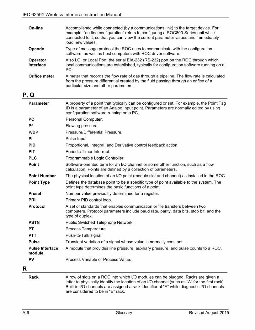
IEC 62591 Wireless Interface Instruction Manual
A-6 Glossary Revised August-2015
On-line Accomplished while connected (by a communications link) to the target device. For example, “on-line configuration” refers to configuring a ROC800-Series unit while connected to it, so that you can view the current parameter values and immediately load new values.
Opcode Type of message protocol the ROC uses to communicate with the configuration software, as well as host computers with ROC driver software.
Operator Interface
Also LOI or Local Port; the serial EIA-232 (RS-232) port on the ROC through which local communications are established, typically for configuration software running on a PC.
Orifice meter A meter that records the flow rate of gas through a pipeline. The flow rate is calculated from the pressure differential created by the fluid passing through an orifice of a particular size and other parameters.
P, Q Parameter A property of a point that typically can be configured or set. For example, the Point Tag
ID is a parameter of an Analog Input point. Parameters are normally edited by using configuration software running on a PC.
PC Personal Computer. Pf Flowing pressure. P/DP Pressure/Differential Pressure. PI Pulse Input. PID Proportional, Integral, and Derivative control feedback action. PIT Periodic Timer Interrupt. PLC Programmable Logic Controller. Point Software-oriented term for an I/O channel or some other function, such as a flow
calculation. Points are defined by a collection of parameters. Point Number The physical location of an I/O point (module slot and channel) as installed in the ROC. Point Type Defines the database point to be a specific type of point available to the system. The
point type determines the basic functions of a point. Preset Number value previously determined for a register. PRI Primary PID control loop. Protocol A set of standards that enables communication or file transfers between two
computers. Protocol parameters include baud rate, parity, data bits, stop bit, and the type of duplex.
PSTN Public Switched Telephone Network. PT Process Temperature. PTT Push-to-Talk signal. Pulse Transient variation of a signal whose value is normally constant. Pulse Interface module
A module that provides line pressure, auxiliary pressure, and pulse counts to a ROC.
PV Process Variable or Process Value.
R Rack A row of slots on a ROC into which I/O modules can be plugged. Racks are given a
letter to physically identify the location of an I/O channel (such as “A” for the first rack). Built-in I/O channels are assigned a rack identifier of “A” while diagnostic I/O channels are considered to be in “E” rack.

IEC 62591 Wireless Interface Instruction Manual
Revised August-2015 Glossary A-7
R (continued) RAM Random Access Memory. RAM is used to store history, data, most user programs, and
additional configuration data. RBX Report-by-exception. RBX always refers to Spontaneous RBX in which the ROC
contacts the host to report an alarm condition. RR Results Register; stores the Signal Value Analog (SVA). RFI Radio Frequency Interference. RI Ring Indicator modem communications signal. ROC Remote Operations Controller microprocessor-based unit that provides remote
monitoring and control. ROCLINK 800 Microsoft® Windows®-based software used to configure functionality in ROC units. ROM Read-only memory. Typically used to store firmware. Flash memory. Rotary Meter A positive displacement meter used to measure flow rate, also known as a Roots
meter. RTC Real-Time Clock. RTD Resistance Temperature Detector. RTS Ready to Send modem communications signal. RTU Remote Terminal Unit. RTV Room Temperature Vulcanizing, typically a sealant or caulk such as silicon rubber. RS-232 Serial Communications Protocol using three or more signal lines, intended for short
distances. Also referred to as the EIA-232 standard. RS-422 Serial Communications Protocol using four signal lines. Also referred to as the EIA-422
standard. RS-485 Serial Communications Protocol requiring only two signal lines. Can allow up to 32
devices to be connected together in a daisy-chained fashion. Also referred to as the EIA-485 standard.
RX or RXD Received Data communications signal.
S SAMA Scientific Apparatus Maker’s Association. Script An uncompiled text file (such as keystrokes for a macro) that a program interprets in
order to perform certain functions. Typically, the end user can easily create or edit scripts to customize the software.
Soft Points A type of ROC point with generic parameters that can be configured to hold data as desired by the user.
SP Setpoint, or Static Pressure. SPI Slow Pulse Input. SPK Speaker. SRAM Static Random Access Memory. Stores data as long as power is applied; typically
backed up by a lithium battery or supercapacitor. SRBX Spontaneous Report-By-Exception. SRBX always refers to Spontaneous RBX in which
the ROC contacts the host to report an alarm condition.

IEC 62591 Wireless Interface Instruction Manual
A-8 Glossary Revised August-2015
S (continued) SVA Signal Value Analog. Stored in the Results Register, it is the analog value that is
passed between functions in an FST. SVD Signal Value Discrete. Stored in the Compare Flag, it is the discrete value that is
passed down the sequence of functions in an FST. System Variables
Configured parameters that describe the ROC; set using ROCLINK software.
T T/C Thermocouple Input. TCP/IP Transmission Control Protocol/Internet Protocol. TDI Time Duration Input. TDO Time Duration Output. Tf Flowing temperature. TLP Type (of point), Logical (or point) number, and Parameter number. TX or TXD Transmitted Data communications signal. Turbine meter A device used to measure flow rate and other parameters.
U Upload Send data, a file, or a program from the ROC to a PC or other host. USB Universal Serial Bus, a serial bus standard used to connect devices.
V-Z V Volts.
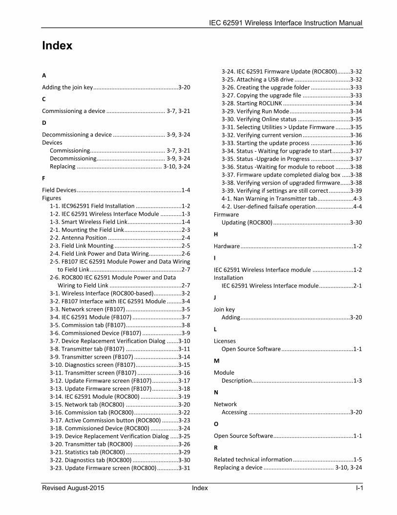
IEC 62591 Wireless Interface Instruction Manual
Revised August-2015 Index I-1
Index
A
Adding the join key ....................................................3-20
C
Commissioning a device .................................... 3-7, 3-21
D
Decommissioning a device ................................ 3-9, 3-24 Devices
Commissioning .............................................. 3-7, 3-21 Decommissioning .......................................... 3-9, 3-24 Replacing .................................................... 3-10, 3-24
F
Field Devices ................................................................1-4 Figures
1-1. IEC962591 Field Installation ............................1-2 1-2. IEC 62591 Wireless Interface Module .............1-3 1-3. Smart Wireless Field Link .................................1-4 2-1. Mounting the Field Link ...................................2-3 2-2. Antenna Position .............................................2-4 2-3. Field Link Mounting .........................................2-5 2-4. Field Link Power and Data Wiring ....................2-6 2-5. FB107 IEC 62591 Module Power and Data Wiring
to Field Link ........................................................2-7 2-6. ROC800 IEC 62591 Module Power and Data
Wiring to Field Link ............................................2-7 3-1. Wireless Interface (ROC800-based) .................3-2 3-2. FB107 Interface with IEC 62591 Module .........3-4 3-3. Network screen (FB107) ..................................3-5 3-4. IEC 62591 Module (FB107) ..............................3-7 3-5. Commission tab (FB107) ..................................3-8 3-6. Commissioned Device (FB107) ........................3-9 3-7. Device Replacement Verification Dialog .......3-10 3-8. Transmitter tab (FB107) ................................3-11 3-9. Transmitter screen (FB107) ...........................3-14 3-10. Diagnostics screen (FB107) ..........................3-15 3-11. Transmitter screen (FB107) .........................3-16 3-12. Update Firmware screen (FB107) ................3-17 3-13. Update Firmware screen (FB107) ................3-18 3-14. IEC 62591 Module (ROC800) .......................3-19 3-15. Network tab (ROC800) ................................3-20 3-16. Commission tab (ROC800) ...........................3-22 3-17. Active Commission button (ROC800) ..........3-23 3-18. Commissioned Device (ROC800) .................3-24 3-19. Device Replacement Verification Dialog .....3-25 3-20. Transmitter tab (ROC800) ...........................3-26 3-21. Statistics tab (ROC800) ................................3-29 3-22. Diagnostics tab (ROC800) ............................3-30 3-23. Update Firmware screen (ROC800) .............3-31
3-24. IEC 62591 Firmware Update (ROC800) ........3-32 3-25. Attaching a USB drive ..................................3-32 3-26. Creating the upgrade folder ........................3-33 3-27. Copying the upgrade file .............................3-33 3-28. Starting ROCLINK .........................................3-34 3-29. Verifying Run Mode .....................................3-34 3-30. Verifying Online status ................................3-35 3-31. Selecting Utilities > Update Firmware .........3-35 3-32. Verifying current version .............................3-36 3-33. Starting the update process ........................3-36 3-34. Status - Waiting for upgrade to start ...........3-37 3-35. Status -Upgrade in Progress ........................3-37 3-36. Status -Waiting for module to reboot .........3-38 3-37. Firmware update completed dialog box .....3-38 3-38. Verifying version of upgraded firmware ......3-38 3-39. Verifying if settings are still correct .............3-39 4-1. Nan Warning in Transmitter tab ......................4-3 4-2. User-defined failsafe operation .......................4-4
Firmware Updating (ROC800) ...............................................3-30
H
Hardware .....................................................................1-2
I
IEC 62591 Wireless Interface module .........................1-2 Installation
IEC 62591 Wireless Interface module .....................2-1
J
Join key Adding ...................................................................3-20
L
Licenses Open Source Software ............................................1-1
M
Module Description ..............................................................1-3
N
Network Accessing ..............................................................3-20
O
Open Source Software .................................................1-1
R
Related technical information .....................................1-5 Replacing a device ........................................... 3-10, 3-24
IEC 62591 Wireless Interface Instruction Manual
I-2 Index Revised August-2015
S
Smart Wireless Field Link ............................................ 1-2
T
Tables 1-1. Additional Technical Information ................... 1-5
Troubleshooting .......................................................... 4-1
U
Updating firmware (ROC800) ................................... 3-30 Updating firmware IEC 62591 module...................... 3-32 USB port ...................................................................... 1-3
W
Wiring ......................................................................... 2-5

IEC 62591 Wireless Interface Instruction Manual
Revised August-2015 Index I-3
[This page is intentionally left blank.]

IE62591 Wireless Interface Instruction Manual
For customer service and technical support, visit www.emersonprocess.com/remote/support
Headquarters: Emerson Process Management Remote Automation Solutions 6005 Rogerdale Road Houston, TX 77072 U.S.A. T +1 281 879 2699 | F +1 281 988 4445 www.EmersonProcess.com/Remote
© 2012-2015 Remote Automation Solutions, a business unit of Emerson Process Management. All rights reserved.
Remote Automation Solutions, a business unit of Emerson Process Management, shall not be liable for technical or editorial errors in this manual or omissions from this manual. REMOTE AUTOMATION SOLUTIONS MAKES NO WARRANTIES, EXPRESSED OR IMPLIED, INCLUDING THE IMPLIED WARRANTIES OF MERCHANTABILITY AND FITNESS FOR A PARTICULAR PURPOSE WITH RESPECT TO THIS MANUAL AND, IN NO EVENT SHALL REMOTE AUTOMATION SOLUTIONS BE LIABLE FOR ANY INCIDENTAL, PUNITIVE, SPECIAL OR CONSEQUENTIAL DAMAGES INCLUDING, BUT NOT LIMITED TO, LOSS OF PRODUCTION, LOSS OF PROFITS, LOSS OF REVENUE OR USE AND COSTS INCURRED INCLUDING WITHOUT LIMITATION FOR CAPITAL, FUEL AND POWER, AND CLAIMS OF THIRD PARTIES.
Emerson Process Management Ltd, Remote Automation Solutions (UK), is a wholly owned subsidiary of Emerson Electric Co. doing business as Remote Automation Solutions, a business unit of Emerson Process Management. FloBoss, ROCLINK, ControlWave, Helicoid, and OpenEnterprise are trademarks of Remote Automation Solutions. AMS, PlantWeb, and the PlantWeb logo are marks owned by one of the companies in the Emerson Process Management business unit of Emerson Electric Co. Emerson Process Management, Emerson and the Emerson logo are trademarks and service marks of the Emerson Electric Co. All other marks are property of their respective owners.
The contents of this publication are presented for informational purposes only. While every effort has been made to ensure informational accuracy, they are not to be construed as warranties or guarantees, express or implied, regarding the products or services described herein or their use or applicability. Remote Automation Solutions reserves the right to modify or improve the designs or specifications of such products at any time without notice. All sales are governed by Remote Automation Solutions’ terms and conditions which are available upon request. Remote Automation Solutions does not assume responsibility for the selection, use or maintenance of any product. Responsibility for proper selection, use and maintenance of any Remote Automation Solutions product remains solely with the purchaser and end-user.
Europe: Emerson Process Management Remote Automation Solutions Unit 8, Waterfront Business Park Dudley Road, Brierley Hill Dudley UK DY5 1LX T +44 1384 487200 | F +44 1384 487258 www.EmersonProcess.com/Remote
North American/Latin America: Emerson Process Management Remote Automation Solutions 6005 Rogerdale Road Houston TX USA 77072 T +1 281 879 2699 | F +1 281 988 4445 www.EmersonProcess.com/Remote
Middle East/Africa: Emerson Process Management Remote Automation Solutions Emerson FZE P.O. Box 17033 Jebel Ali Free Zone – South 2 Dubai U.A.E. T +971 4 8118100 | F +971 4 8865465 www.EmersonProcess.com/Remote
Asia-Pacific: Emerson Process Management Remote Automation Solutions 1 Pandan Crescent Singapore 128461 T +65 6777 8211| F +65 6777 0947 www.EmersonProcess.com/Remote
Remote Automation Solutions