ieee transactions on computer-aided …seelab.ucsd.edu/papers/tcad2011-sabry_et_al_1.pdfdigital...
TRANSCRIPT

IEEE TRANSACTIONS ON COMPUTER-AIDED DESIGN OF INTEGRATED CIRCUITS AND SYSTEMS, VOL. 30, NO. 12, DECEMBER 2011 1883
Energy-Efficient Multiobjective Thermal Controlfor Liquid-Cooled 3-D Stacked Architectures
Mohamed M. Sabry, Student Member, IEEE, Ayse K. Coskun, Member, IEEE, David Atienza, Member, IEEE,Tajana Simunic Rosing, Member, IEEE, and Thomas Brunschwiler, Member, IEEE
Abstract—3-D stacked systems reduce communication delay inmultiprocessor system-on-chips (MPSoCs) and enable heteroge-neous integration of cores, memories, sensors, and RF devices.However, vertical integration of layers exacerbates temperature-induced problems such as reliability degradation. Liquid coolingis a highly efficient solution to overcome the accelerated thermalproblems in 3-D architectures; however, it brings new challengesin modeling and run-time management for such 3-D MPSoCswith multitier liquid cooling. This paper proposes a novel design-time/run-time thermal management strategy. The design-timephase involves a rigorous thermal impact analysis of variousthermal control variables. We then utilize this analysis to designa run-time fuzzy controller for improving energy efficiency in 3-DMPSoCs through liquid cooling management and dynamic volt-age and frequency scaling (DVFS). The fuzzy controller adjuststhe liquid flow rate dynamically to match the cooling demandof the chip for preventing overcooling and for maintaining astable thermal profile. The DVFS decisions increase chip-levelenergy savings and help balance the temperature across thesystem. Our controller is used in conjunction with temperature-aware load balancing and dynamic power management strategies.Experimental results on 2-tier and 4-tier 3-D MPSoCs showthat our strategy prevents the system from exceeding the giventhreshold temperature. At the same time, we reduce coolingenergy by up to 63% and system-level energy by up to 21%in comparison to statically setting a flow rate setting to handleworst-case temperatures.
Index Terms—3-D integration, liquid cooling, multiprocessorSoC (MPSoC), thermal management.
I. Introduction
3-D INTEGRATION is a recently proposed designmethod to overcome the limitations with respect
Manuscript received May 19, 2011; revised July 19, 2011; accepted July 21,2011. Date of current version November 18, 2011. This work was supportedin part by the PRO3D EU FP7-ICT-248776 Project, and in part by the Nano-Tera.ch RTD Project CMOSAIC (ref. 123618), which is financed by theSwiss Confederation and scientifically evaluated by Swiss National ScienceFoundation. This paper was recommended by Associate Editor Y. Xie.
M. M. Sabry and D. Atienza are with the Embedded Systems Laboratory,École Polytechnique Federale de Lausanne, Lausanne 1015, Switzerland (e-mail: [email protected]; [email protected]).
A. K. Coskun is with the Department of Electrical and Computer Engineer-ing, Boston University, Boston, MA 02215 USA (e-mail: [email protected]).
T. S. Rosing is with the Department of Computer Science and Engineering,University of California at San Diego, San Diego, CA 92093 USA (e-mail:[email protected]).
T. Brunschwiler is with IBM Research GmbH, Zurich Research Laboratory,Zurich 8803, Switzerland (e-mail: [email protected]).
Color versions of one or more of the figures in this paper are availableonline at http://ieeexplore.ieee.org.
Digital Object Identifier 10.1109/TCAD.2011.2164540
to the delay, bandwidth, and power consumption of the in-terconnects in large multicore chips, while reducing the chipfootprint and improving the fabrication yield. However, hightemperatures resulting from higher thermal resistivity [17],[28] are among the main challenges for designing 3-D multi-processor system-on-chips (MPSoCs). In addition, it is moredifficult to remove the heat from 3-D MPSoCs as cores may belocated at different tiers and have significantly different heat-ing/cooling rates in comparison to conventional 2-D chips [9].3-D MPSoCs are also prone to larger thermal variations, whichhave adverse effects on system reliability, performance, andcooling costs [11].
A number of thermal management techniques have beenproposed for controlling temperature on 2-D (single-tier)MPSoCs. Dynamic voltage and frequency scaling (DVFS)and thread migration/scheduling based on thermal feedbackare examples of such techniques [14]. Recent research hasextended 2-D management techniques for workload schedulingand DVFS-based thermal management in 3-D MPSoCs [9],[44], [45]. However, as power densities, number of cores, andnumber of tiers increase, extremely high temperature valuesappear in 3-D stacks [44], resulting in severe restrictions inhigh-performance 3-D MPSoC design.
Interlayer liquid cooling is an attractive solution to addressthe high temperatures in 3-D chips, due to the higher heatremoval capability of liquids in comparison to air [7], [10].However, we need to integrate liquid cooling management withtask scheduling and DVFS to maximize the energy efficiencyand reliability of high-performance 3-D MPSoCs. In addition,previous work has shown that as workload dynamics changeat run-time, choosing the flow rate setting dynamically to meetthe cooling demand saves significant energy [10].
Combining various control knobs in a single low-overheadoptimum controller is a highly challenging task, as the controlparameters differ in their time constants, performance/energyoverheads, and benefits. For example, DVFS has an overheadin the order of tens to hundreds of microseconds, whileflow rate changes may take hundreds of milliseconds. Hence,simultaneously utilizing such distinct control knobs at run-time requires a thorough understanding of their impact andinteractions.
In this paper, we propose a combined design-time/run-timethermal management strategy for 3-D MPSoCs to interpretcurrent system state (temperature, power, and workload) with adegree of uncertainty and flexibility. In particular, we advance
0278-0070/$26.00 c© 2011 IEEE

1884 IEEE TRANSACTIONS ON COMPUTER-AIDED DESIGN OF INTEGRATED CIRCUITS AND SYSTEMS, VOL. 30, NO. 12, DECEMBER 2011
the state-of-the-art on dynamic thermal management (DTM)for 3-D MPSoCs in the following directions.
1) We perform a thorough design-time thermal impactanalysis of various DTM methods (i.e., flow rate control,DVFS, and task scheduling/migration) in 3-D MPSoCswith interlayer liquid cooling to identify a set of optimaldecisions in achieving energy-efficient thermal manage-ment with minimal performance degradation.
2) We utilize this study to design a fuzzy controller thatextends previous work [30] by including a completestability and implementation complexity analysis. Thecontroller is able to trigger appropriate flow rate andDVFS adjustments based on the system’s temperature,workload requirements, and spatial location of the com-putational units and caches.
3) We analyze the benefits of the state-of-the-art tempera-ture-aware job scheduling methods [9], [44] in our DTMscheme for 3-D MPSoC with liquid cooling. We proposea novel job scheduler which takes the physical locationsof the units in the 3-D stack into consideration tostabilize the temperature on the die and to improvecooling efficiency without affecting performance.
4) We provide extensive experimental evaluation on 2-tier and 4-tier 3-D MPSoCs by comparing our thermalmanagement approach with respect to state-of-the-artDTM techniques [10], [30], [44] for a large number ofmetrics, such as peak temperatures, thermal gradients,energy efficiency, and performance degradation. Theseexperiments show that our strategy completely removesthermal hot spots in the 3-D stacks, while saving coolingenergy by up to 63% and 45%, and system-level energyby up to 21% and 18%, in comparison to using a staticworst-case flow rate setting and in comparison to usinga look-up table-based control [10], respectively.
5) We analyze how core and cache temperatures in differentlocations of the 3-D MPSoC are affected by the liquidflow to reduce the pumping power and the thermalgradients in the 3-D stack.
The rest of this paper starts with an overview of the priorwork in Section II. Then, Section III describes our developedthermal model for liquid-cooled 3-D MPSoCs. Next, we de-scribe the proposed design-time/run-time thermal managementstrategy in Section IV. In Section V, we explore the thermalimpact analysis of various thermal control knobs on the 3-D MPSoCs temperature. Section VI describes our new fuzzycontroller for DTM in 3-D MPSoCs with liquid cooling, andwe present the experimental results in Section VII. Finally,Section VIII summarizes the main conclusions of this paper.
II. Related Work
A. Accurate and Compact Thermal Modeling of 2-D/3-D ICs
Accurate thermal modeling is critical in system designand evaluation. HotSpot [33] is a R-C network-based ther-mal model that calculates transient temperature response fora given power trace. To reduce the potentially long ther-mal simulation time in HotSpot for large MPSoCs, recent
work proposes a thermal emulation framework using field-programmable gate arrays [2]. Latest versions of HotSpotinclude 3-D modeling, and methods to extend HotSpot forliquid-cooled 3-D MPSoCs are available [8]. 3-D interlayercooling emulator (3D-ICE) [34] is a new thermal modelingtool specifically designed for transient thermal analysis of 3-Dstacks, including interlayer liquid cooling modeling. The au-thors showed that their modeling and simulation frameworkcan be extended to account for different cavity structures, suchas pin-fins [35]. Feng et al. [15] introduced a thermal simu-lation framework of 3-D stacks where graphical processingunits are used for accelerating temperature calculation. Allthese methods to model and speedup 3-D MPSoC thermalsimulations are complementary to our paper.
B. Interlayer Liquid Cooling
The use of convection in microchannels to cool down highpower density chips has been an active area of researchsince the initial work by Tuckerman and Pease [41]. Theirliquid cooling system can remove 1000 W/cm2; however, thevolumetric flow rate and the pressure drop are too largefor practical applications in 3-D integrated circuits (ICs).Recent work shows that back-side liquid cold plates, i.e.,staggered microchannel and distributed return jet plates, canhandle up to 400 W/cm2 in single-chip applications [6]. Theheat removal capability of interlayer heat-transfer with pin-fininline structures for 3-D chips has been also investigated [7],[18]. At a chip size of 1 cm2 and maximal difference betweenjunction and liquid cooling temperatures of 60 K, the heat-removal performance is more than 200 W/cm2 at interconnectpitches larger than 50 μm. However, research in liquid coolinghas typically developed thermal packaging solutions ratherthan utilizing active cooling in DTM, which is the focus ofour paper.
C. DTM of 3-D MPSoCs
Prior work on thermal management for 3-D MPSoCs mainlyaddresses design-time optimization, such as thermally awarefloorplanning [16], integrating thermal via planning in the3-D floorplanning process [22], and joint optimization thattargets temperature, power interconnect, and signal wires [20].A tradeoff study in recent work compares thermal behaviorand interconnect congestion for two 3-D MPSoC coolingtechnologies: inter-tier liquid cooling and thermal through-silicon-vias (TSVs) [20]. This paper shows that inter-tier liquidcooling has superior cooling abilities, but induces limitationsfor TSVs and increases cost with respect to using thermalTSVs only.
Recent work considers DTM for 3-D MPSoCs. Zhu et al.[45] evaluated several policies for task migration and DVFS byexploring thermal profiles of adjacent processing cores onthe same vertical column (interlayer adjacent) or within thesame layer (intralayer). Zhou et al. [44] integrated a thermallyaware task scheduler with DVFS on a 2-tier system witheight cores. A recent paper proposed a temperature-awarescheduling method specifically designed for air-cooled (AC) 3-D systems [9]. Their method considered thermal heterogeneityamong the 3-D MPSoC layers; however, it does not studyinterlayer cooling. Prior work on DTM in AC 3-D systems
SABRY et al.: ENERGY-EFFICIENT MULTIOBJECTIVE THERMAL CONTROL FOR LIQUID-COOLED 3-D STACKED ARCHITECTURES 1885
demonstrated very high temperatures (85–120 °C), motivatingthe search for alternative energy-efficient cooling techniquesbeyond conventional methods.
Prior liquid cooling work [8] evaluated existing thermalmanagement policies on a 3-D MPSoC with a fixed-flowrate value, and the benefits of using a policy to increment/decrement the flow rate based on temperature measurements.Our recent paper [10] considered the energy efficiency of 3-D MPSoCs with variable flow rate adjustment and thermallyaware load balancing, without utilizing DVFS for increasedenergy savings. Recently, Qian et al. [29] explored the use ofa cyber-physical approach to manage the temperature of 3-DMPSoCs with inter-tier liquid cooling. They construct theircontrol mechanism with software-based thermal estimationand prediction. They use a nonuniform liquid flow in differentmicrochannels, to meet the cooling demands of differentmodules.
This paper brings several major contributions over priorwork. First, we study the thermal impact of various thermalmanagement methods (flow rate control, DVFS, and taskscheduling/migration) in 3-D MPSoCs to identify a set ofoptimal decisions in achieving energy-efficient thermal man-agement with minimal performance degradation. Second, weutilize this study in designing a fuzzy controller that generatesthe appropriate control decisions, as well as discussing thecontroller’s use in conjunction with a novel job scheduler tofurther improve the cooling efficiency without affecting perfor-mance. Finally, we demonstrate how design-time optimizationcan help improve energy efficiency in 3-D systems with liquidcooling.
III. Thermal Modeling Framework for
Liquid-Cooled 3-D MPSoCs
Modeling the temperature dynamics of liquid-cooled3-D MPSoC architectures consists of forming the grid-levelthermal R-C network model of the whole stack, modelingthe TSVs and the microchannels [34], [45], and modeling theimpact of the pump and coolant flow rate.
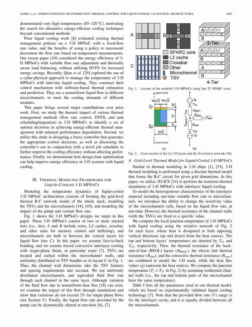
Fig. 1 shows the 3-D MPSoCs designs we target in thispaper. These 3-D MPSoCs consist of two or more stackedtiers (i.e., tiers A and B include cores, L2 caches, crossbar,and other units for memory control and buffering), andmicrochannels are built in between the vertical layers forliquid flow (tier C). In this paper, we assume face-to-backbonding, and we assume forced convective interlayer coolingwith single-phase fluids, in particular water [7]. TSVs arelocated and etched within the microchannel walls, anduniformly distributed in TSV bundles as in layout C in Fig. 1.Thus, the channel wall dimensions take the TSV featuresand spacing requirements into account. We use uniformlydistributed microchannels, and equivalent fluid flow ratethrough each channel in the same layer. Although variationof the fluid flow due to nonuniform heat flux [18] can exist,we examine the impact of this flow through simulations andshow that variations do not exceed 2% for single-phase flows(see Section V). Finally, the liquid flow rate provided by thepump can be dynamically altered at run-time [6], [7].
Fig. 1. Layouts of the modeled 3-D MPSoCs using Sun T1 SPARC cores.
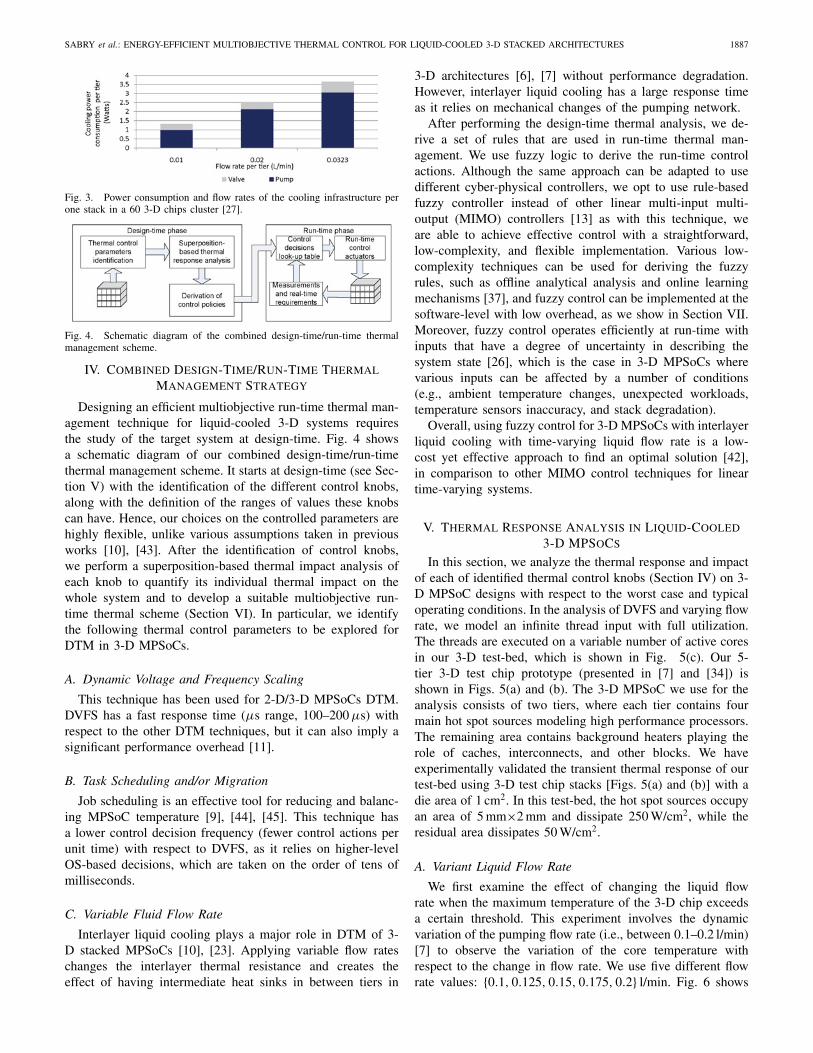
Fig. 2. Cross-section of the (a) 3-D layers and the (b) resistive network [10].
A. Grid-Level Thermal Model for Liquid-Cooled 3-D MPSoCs
Similar to thermal modeling in 2-D chips [1], [33], 3-Dthermal modeling is performed using a discrete thermal modelthat forms the R-C circuit for given grid dimensions. In thispaper, we utilize 3D-ICE [34] to perform the transient thermalsimulation of 3-D MPSoCs with interlayer liquid cooling.
To model the heterogeneous characteristics of the interlayermaterial including run-time variable flow rate in microchan-nels, we introduce the ability to change the resistivity valueof the microchannels cells, based on the liquid flow rate, atrun-time. However, the thermal resistance of the channel walls(with the TSVs) are fixed to a specific value.
We compute the local junction temperature of 3-D MPSoCswith liquid cooling using the resistive network of Fig. 2for each layer, where heat is dissipated to both opposingvertical directions (up and down) from the heat sources. Thetop and bottom layers’ temperatures are denoted by TS1 andTS2, respectively. Then, the thermal resistance of the back-end-of-line (BEOL) layers (RBEOL), the silicon slab thermalresistance (Rslab), and the convective thermal resistance (Rconv)are combined to model the 3-D stack, while the heat fluxvalues (q) represent the heat sources. We compute the junctiontemperature (Tj = TS1 in Fig. 2) by assuming isothermal chan-nel walls (i.e., the top and bottom parts of the microchannelhave the same temperature).
Table I lists all the parameters used in our thermal model,which are based on experimentally validated liquid coolingtechnology [7]. Note that the provided flow rate (V ) range isfor the interlayer cavity, and it is equally divided between allthe microchannels.

1886 IEEE TRANSACTIONS ON COMPUTER-AIDED DESIGN OF INTEGRATED CIRCUITS AND SYSTEMS, VOL. 30, NO. 12, DECEMBER 2011
TABLE I
Parameters for Computing (1)
Parameter Definition Value
Rth−BEOL Thermal resistance (3)of wiring levels
tB BEOL thickness (Fig. 2) 12μm
kBEOL Conductivity of wiring levels 2.25 W/(m·K)
Rth−heat Effective thermal resistance (5)
Aheater Heater area Area of grid cell
cp Coolant heat capacity 4183 J/(kg·K)
ρ Coolant density 998 kg/m3
V Volumetric flow rate per cavity 0.01–0.0323 l/min
h Heat-transfer coefficient 371323 W/(m2 ·K)
wc Channel width (Fig. 2) 50 μm
ww Wall width (Fig. 2) 100 μm
tc Channel thickness (Fig. 2) 100 μm
ts Silicon slab thickness (Fig. 2) 50 μm
p Channel pitch (Fig. 2) 150 μm
The junction temperature change (shown in Fig. 2) is a sumof the following three components: 1) the thermal gradient dueto conduction (�Tcond); 2) the change in coolant temperature,which increases linearly with position along the channel dueto heat absorption (�Theat); and 3) the convective (�Tconv)portion, which is independent of the flow rate with fullydeveloped hydrodynamic and thermal boundary layers thathave been reached [7]. Hence, the total temperature rise onthe junction (�Tj) can be computed as follows:
�Tj = �Tcond + �Theat + �Tconv. (1)
The thermal gradient due to heat conduction through BEOLlayer (�Tcond) can be computed using the definitions andvalues of tB and kBEOL in Table I as follows:
�Tcond = Rth−BEOL · q1 (2)
Rth−BEOL =tB
kBEOL. (3)
The temperature change between two adjacent cells due toheat absorption (�Theat) is computed as follows:
�Theat = (q1 + q2) · Rth−heat (4)
Rth−heat =Aheater
cp · ρ · V. (5)
Finally, (6) and (7) show how to calculate the temperaturechange due to convection (�Tconv). The heat-transfer coef-ficient (h) is dependent on the hydraulic diameter, Nusseltnumber, and conductivity of the fluid [7]. As the effectiveheat-transfer coefficient (heff ) is not affected by flow ratechanges with developed boundary layers, we compute thisparameter prior to simulation and use it during the experiments(Section VII). Fig. 2 demonstrates wc, tc, and p, and Table Ishows their definitions and values.
�Tconv = (q1 + q2) · heff (6)
heff = h2 · (wc + tc)
p. (7)
In our target 3-D MPSoCs, we use copper TSVs with 50 μmdiameter and 150 μm pitch. These particular dimensions havebeen used in 3-D ICs with interlayer cooling in previouswork [3], [19]. Considering the dimensions and pitch require-ments of microchannels and TSVs, there are 66 microchannelsin each cavity (tier C), and each cavity is located betweenevery two silicon tiers (A or B). Thus, there are 66 and
TABLE II
Parameters Definition Used in Relating Flow Rate to the
Applied Pressure Difference
Parameter Definition
ε Cavity porosity (0.33)κ Cavity permeability (7.17E-11 m2)μ Dynamic viscosity (1E-3 Pascal· s at 300 K)
�P Pressure difference between the inlet and outlet ports (1 bar)L Channel length
198 microchannels in the 2-tier and 4-tier 3-D MPSoCs,respectively. Based on previous work [3], [8], we assign auniform TSV density for the interlayer material.
B. Modeling the Pump and Liquid Flow Rate
All the microchannels are connected to a pump to receivethe coolant. The pump injects the fluid at a certain pressure dif-ference required by the system. In accordance with prior workon liquid cooling technology validation for 3-D stacks [7], wefix the maximum applied pressure on the stack to 1 bar. Theflow velocity within the microchannels is governed by:
νbulk =νdarcy
ε(8)
νdarcy =κ
μ· ∇P (9)
∇P =�P
L(10)
where νbulk is the actual velocity in the channel, and theother symbols are defined in Table II. These equations showthat the fluid velocity is dependent on the applied pressuredifference and on the fluid temperature via the dynamicviscosity. In particular, if the fluid temperature increasesthe dynamic viscosity decreases, and the fluid moves at ahigher speed. However, in our experiments, we have observedthat the change in the fluid temperature with nonuniformheat fluxes does not exceed 10°, which in turn negligiblyaffects the dynamic viscosity. Therefore, we assume thatthe fluid velocity remains constant at a constant pressuregradient.
In a high-performance computing cluster, several chips areincluded in a set of racks and a central pump must be usedfor several 3-D stacks for reducing the cost [27]. Hence, acentrifugal pump EMB MHIE [31] is responsible for the fluidinjection to a cluster of nodes via a pumping network. Thispump has the capability of producing large discharge ratesat small pressure heads. To enable different flow rates foreach stack, the cooling infrastructure includes valves in thenetwork. We assume normally closed valves (NCVs) providedby the Festo group [32]. NCVs use external power to reducethe pressure drop and to increase the flow rate. Fig. 3 showsthe pump and valve power consumption for three flow ratesettings of a single stack deployed in a cluster with 60similar 3-D computing stacks, as proposed in the Aquasardata-center design [27]. The maximum energy required toinject the fluid to all stacks is approximately 180 W, whichis a significant overhead to the whole system as this value issimilar to the energy consumed by a 4-tier 3-D chip. Thus,the energy consumed in the liquid cooling subsystem shouldbe minimized.
SABRY et al.: ENERGY-EFFICIENT MULTIOBJECTIVE THERMAL CONTROL FOR LIQUID-COOLED 3-D STACKED ARCHITECTURES 1887
Fig. 3. Power consumption and flow rates of the cooling infrastructure perone stack in a 60 3-D chips cluster [27].
Fig. 4. Schematic diagram of the combined design-time/run-time thermalmanagement scheme.
IV. Combined Design-Time/Run-Time Thermal
Management Strategy
Designing an efficient multiobjective run-time thermal man-agement technique for liquid-cooled 3-D systems requiresthe study of the target system at design-time. Fig. 4 showsa schematic diagram of our combined design-time/run-timethermal management scheme. It starts at design-time (see Sec-tion V) with the identification of the different control knobs,along with the definition of the ranges of values these knobscan have. Hence, our choices on the controlled parameters arehighly flexible, unlike various assumptions taken in previousworks [10], [43]. After the identification of control knobs,we perform a superposition-based thermal impact analysis ofeach knob to quantify its individual thermal impact on thewhole system and to develop a suitable multiobjective run-time thermal scheme (Section VI). In particular, we identifythe following thermal control parameters to be explored forDTM in 3-D MPSoCs.
A. Dynamic Voltage and Frequency Scaling
This technique has been used for 2-D/3-D MPSoCs DTM.DVFS has a fast response time (μs range, 100–200 μs) withrespect to the other DTM techniques, but it can also imply asignificant performance overhead [11].
B. Task Scheduling and/or Migration
Job scheduling is an effective tool for reducing and balanc-ing MPSoC temperature [9], [44], [45]. This technique hasa lower control decision frequency (fewer control actions perunit time) with respect to DVFS, as it relies on higher-levelOS-based decisions, which are taken on the order of tens ofmilliseconds.
C. Variable Fluid Flow Rate
Interlayer liquid cooling plays a major role in DTM of 3-D stacked MPSoCs [10], [23]. Applying variable flow rateschanges the interlayer thermal resistance and creates theeffect of having intermediate heat sinks in between tiers in
3-D architectures [6], [7] without performance degradation.However, interlayer liquid cooling has a large response timeas it relies on mechanical changes of the pumping network.
After performing the design-time thermal analysis, we de-rive a set of rules that are used in run-time thermal man-agement. We use fuzzy logic to derive the run-time controlactions. Although the same approach can be adapted to usedifferent cyber-physical controllers, we opt to use rule-basedfuzzy controller instead of other linear multi-input multi-output (MIMO) controllers [13] as with this technique, weare able to achieve effective control with a straightforward,low-complexity, and flexible implementation. Various low-complexity techniques can be used for deriving the fuzzyrules, such as offline analytical analysis and online learningmechanisms [37], and fuzzy control can be implemented at thesoftware-level with low overhead, as we show in Section VII.Moreover, fuzzy control operates efficiently at run-time withinputs that have a degree of uncertainty in describing thesystem state [26], which is the case in 3-D MPSoCs wherevarious inputs can be affected by a number of conditions(e.g., ambient temperature changes, unexpected workloads,temperature sensors inaccuracy, and stack degradation).
Overall, using fuzzy control for 3-D MPSoCs with interlayerliquid cooling with time-varying liquid flow rate is a low-cost yet effective approach to find an optimal solution [42],in comparison to other MIMO control techniques for lineartime-varying systems.
V. Thermal Response Analysis in Liquid-Cooled
3-D MPSoCs
In this section, we analyze the thermal response and impactof each of identified thermal control knobs (Section IV) on 3-D MPSoC designs with respect to the worst case and typicaloperating conditions. In the analysis of DVFS and varying flowrate, we model an infinite thread input with full utilization.The threads are executed on a variable number of active coresin our 3-D test-bed, which is shown in Fig. 5(c). Our 5-tier 3-D test chip prototype (presented in [7] and [34]) isshown in Figs. 5(a) and (b). The 3-D MPSoC we use for theanalysis consists of two tiers, where each tier contains fourmain hot spot sources modeling high performance processors.The remaining area contains background heaters playing therole of caches, interconnects, and other blocks. We haveexperimentally validated the transient thermal response of ourtest-bed using 3-D test chip stacks [Figs. 5(a) and (b)] with adie area of 1 cm2. In this test-bed, the hot spot sources occupyan area of 5 mm×2 mm and dissipate 250 W/cm2, while theresidual area dissipates 50 W/cm2.
A. Variant Liquid Flow Rate
We first examine the effect of changing the liquid flowrate when the maximum temperature of the 3-D chip exceedsa certain threshold. This experiment involves the dynamicvariation of the pumping flow rate (i.e., between 0.1–0.2 l/min)[7] to observe the variation of the core temperature withrespect to the change in flow rate. We use five different flowrate values: {0.1, 0.125, 0.15, 0.175, 0.2} l/min. Fig. 6 shows
1888 IEEE TRANSACTIONS ON COMPUTER-AIDED DESIGN OF INTEGRATED CIRCUITS AND SYSTEMS, VOL. 30, NO. 12, DECEMBER 2011
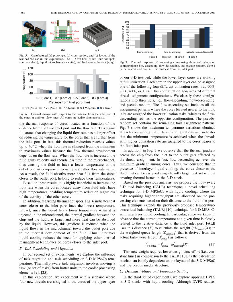
Fig. 5. Manufactured (a) prototype, (b) cross-section, and (c) layout of thetest-bed we use in this exploration. The 3-D test-bed (c) has four hot spotssources (black), liquid microchannels (white), and background heaters (gray).
Fig. 6. Thermal change with respect to the distance from the inlet port ofthe cores at different flow rates. All cores are active simultaneously.
the thermal response of cores located as a function of thedistance from the fluid inlet port and the flow rate. This figureillustrates that changing the liquid flow rate has a larger effecton reducing the temperature for the cores that are further fromthe inlet port. In fact, this thermal reduction reaches valuesup to 40 °C when the flow rate is changed from the minimumto maximum values because the flow thermal developmentdepends on the flow rate. When the flow rate is increased, thefluid gains velocity and spends less time in the microchannel,thus causing the fluid to have a lower temperature at theoutlet port in comparison to using a smaller flow rate value.As a result, the fluid absorbs more heat flux from the corescloser to the outlet port, helping to reduce their temperatures.
Based on these results, it is highly beneficial to increase theflow rate when the cores located away from fluid inlet havehigh temperatures, enabling temperature reduction regardlessof the activity of the other cores.
In addition, regarding thermal hot spots, Fig. 6 indicates thatcores closer to the inlet ports have the lowest temperature.In fact, since the liquid has a lower temperature when it isinjected in the microchannel, the thermal gradient between thechip and the liquid is larger and more heat can be absorbedby the liquid. However, this gradient is reduced when theliquid flows in the microchannel toward the outlet port dueto the thermal development of the fluid. Thus, interlayerliquid cooling reduces the need for applying other thermalmanagement techniques on cores closer to the inlet port.
B. Task Scheduling and Migration
In our second set of experiments, we explore the influenceof task migration and task scheduling on 3-D MPSoCs tem-perature. Thermally-aware task migration involves moving atask (or set of tasks) from hotter units to the cooler processingelements [9], [25].
In this exploration, we experiment with a scenario wherefour new threads are assigned to the cores of the upper layer
Fig. 7. Thermal response of processing cores using three task allocationconfigurations: flow-ascending, flow-descending, and pseudo-random. Core 1is the nearest and core 4 is the furthest from the inlet port.
of our 3-D test-bed, while the lower layer cores are workingat full utilization. Each core in the upper layer can be assignedone of the following four different utilization rates, i.e., 90%,70%, 40%, or 10%. This configuration generates 24 differentthread assignment configurations. We classify these configu-rations into three sets, i.e., flow-ascending, flow-descending,and pseudo-random. The flow-ascending set includes all theassignment patterns where the cores located nearer to the fluidinlet are assigned the lower utilization tasks, whereas the flow-descending set has the opposite configuration. The pseudo-random set contains the remaining task assignment patterns.Fig. 7 shows the maximum temperature variations obtainedat each core among the different configurations and indicatesthat the minimum temperature is achieved when the threadswith higher utilization rate are assigned to the cores nearer tothe fluid inlet port.
In addition, in Fig. 7 we observe that the thermal gradientacross the chip from the inlet to the outlet gets affected bythe thread assignment. In fact, flow-descending achieves theminimum gradient among cores. Thus, we conclude that inpresence of interlayer liquid cooling, the cores closer to thefluid inlet can be assigned a significantly larger task set withoutcreating thermal issues in the 3-D stack.
Based on the previous analysis, we propose the flow-aware3-D load balancing (FALB) technique, a novel schedulingtechnique for 3-D MPSoCs with liquid cooling, where thetasks requiring higher throughput are allocated on the pro-cessing elements based on their distance to the fluid inlet port.This technique extends the previously proposed temperature-aware load balancing (TALB) [10] technique for 3-D MPSoCswith interlayer liquid cooling. In particular, since we know inadvance that the current temperature at a given time is closelyrelated to the relative distance to the fluid inlet port, FALBuses this distance (X) to calculate the weight (ωi
Thermal(X)) inthe weighted queue length (liweighted) that is derived from theactual task-queue length (liqueue) as follows:
liweighted = liqueue · ωiThermal(X). (11)
This new weight requires lower design-time effort (i.e., con-stant time) in comparison to the TALB [10], as the calculationmechanism is only dependent on the layout of the 3-D MPSoCand the porous media structure.
C. Dynamic Voltage and Frequency Scaling
In the third set of experiments, we explore applying DVFSin 3-D stacks with liquid cooling. Although DVFS reduces

SABRY et al.: ENERGY-EFFICIENT MULTIOBJECTIVE THERMAL CONTROL FOR LIQUID-COOLED 3-D STACKED ARCHITECTURES 1889
the speed of the cores and can imply a degradation ofthe throughput for real-life workloads (see Section VII), inthis analysis, we consider the execution of a thread of aninfinite duration. The performance degradation is not takeninto account as the main goal is to explore the thermal impactin this experiment.
To examine the thermal effects of DVFS, we use a simpletwo-threshold policy, where the frequency of a certain coreis decreased when the temperature exceeds a high thresholdvalue T1, and increased when the temperature falls belowanother value T2, where T1 > T2. We assume that thereare three voltage/frequency (VF) settings for each process-ing element, as proposed in [11]. The DVFS settings are(V, F ), (0.91 V, 0.83 F ), and (0.83 V, 0.67 F ). We compute theVF switching frequency for three different (T1, T2) pairs:[(77, 73), (80, 78), (85, 82)] °C.
Our experiments indicate that core location plays an im-portant role in the use of DVFS for temperature control, asshown in Fig. 8. Cores located near the fluid inlet port donot experience a significant number of VF changes due totheir very low temperature. However, as cores are locatedfurther from the inlet port, more frequent scaling occurs tomaintain the temperature of these elements within the definedthresholds. In fact, when the thermal control thresholds areat the lowest range (77, 73 °C), middle-distance elements (i.e.,0.5 mm from the input port) change their VF values 50% ofthe possible switching moments, while the elements locatedfurthest from the inlet port (i.e., 0.7 mm) cannot maintaintheir temperature within the defined thresholds, and they scale-down their VF to the lowest value. In addition, cores near theoutlet port have higher temperatures than the threshold, thusVF changes occur less frequently.
When the temperature control threshold is higher(85, 82 °C), the temperatures of the cores near the outlet portget close to these thresholds, thus they perform DVFS moreoften with respect to the cores closer to the inlet port. Also,as shown in Fig. 8, the cores located at 0.7 mm from the inletport have fewer VF changes in comparison to the cores at0.5 mm. This behavior is related to the impact of VF scalingon these cores: when the VF is scaled down to reduce thetemperature, DVFS has a higher impact on the cores closer tothe inlet port than those further from the inlet port. As a result,the time needed to cool down the cores near the inlet port(0.5 mm) to a temperature below the 82 °C threshold is shorterin comparison to the cores at a further distance, which triggersVF scaling to higher levels sooner in closer-to-inlet cores.
VI. Integrated Flow Rate and DVFS Fuzzy
Controller
This section provides the details of our fuzzy controller,which combines DVFS and dynamic flow rate management toachieve low operating temperatures while saving energy andmaintaining the desired performance. In our system, we takethe control decisions based on two dynamically changing in-puts, temperature (T) and workload utilization (U), and on therelative distance from the inlet port as a third static input (D).
Fig. 8. VF switching frequency of processing cores with respect to thedistance from the fluid inlet, using three different temperature threshold sets.
Fig. 9. Schematic diagram of the fuzzy-based thermal controller.
A. Controller Architecture
Our fuzzy controller is a Takagi-Sugeno fuzzy model [38],which defines the rules as a function of the inputs. In thisfuzzy model, the rules are given using the following form:
IF x1 is Ai1 AND x2 is Ai2 ... AND xk is Aik
THEN Yi = fi(x1, x2, . . . , xk), i = 1, 2, . . . , n
where xj|j = 1, 2, . . . , k are the inputs, Aij values refer to thepredefined ranges, and Yi is the output function. A schematicdiagram of the building blocks of the fuzzy controller isshown in Fig. 9. We next discuss the components of the fuzzycontroller.
1) Fuzzifier: Fuzzifier is the interface between the fuzzycontroller and the outside world, as it transforms any numericalinput to its corresponding fuzzy value. For any variable(x = xo, xo ∈ R) where R is the range of x, a fuzzy functionμo(x) is generated to be used with the rule-base in orderto infer the proper output. In our controller, we deploy asingleton fuzzifier [26], which is suitable in our context dueto its low implementation complexity. For run-time thermalmanagement, the fuzzy function model is:
μo(x) = 1 when x = xo, 0 otherwise.
2) Fuzzy Membership Functions: Membership functionstranslate a variable numerical range R to a linguistic one,such that {∀x ∈ R, μ(x) ∈ [0, 1]}. In the membershipfunction selection, a key aspect is full coverage of the inputvariable range R with N fuzzy functions [26], such that{∀ x ∈ R,
⋃Ni=1 μi(x) > 0}. In our fuzzy-based thermal
controller, each variable has full range coverage through threemembership functions. We use triangular and trapezoidal-based memberships to minimize the controller’s executioncomplexity [26] via these piecewise linear functions, as it is

1890 IEEE TRANSACTIONS ON COMPUTER-AIDED DESIGN OF INTEGRATED CIRCUITS AND SYSTEMS, VOL. 30, NO. 12, DECEMBER 2011
TABLE III
Fuzzy-Derived Rule-Base
IF THEN
D Is AND T Is AND U Is VF Is AND Flow Rate Is
L X X H L
M L X H LM M L L LM M M M MM M H M MM H L L LM H M M MM H H M H
H L X H LH M L L LH M M M LH M H H MH H L L MH H M L HH H H M H
X is a “don’t care.”
illustrated in the upper graph in Fig. 10. This figure shows thelow (L), medium (M), and high (H) membership functionsused to describe the core utilization rates and temperaturevalues. These functions, as shown in the figure, cover the fullrange of the measured input variables.
3) Rule-Base: This module is the basic building blockin the controller, which contains all the IF-THEN rules re-lating the outputs to the inputs. We present these rules inSection VI-B.
4) Inference Engine: This block is used in the evaluation ofthe output functions implied by the rule-base, the membershipfunctions, and the fuzzified inputs [26].
5) Defuzzifier: This block transforms the outputs from theinference engine into numerical values. Since we use a Takagi-Sugeno type controller, the defuzzifier applies a weighted sumfrom each implied IF clause to compute the output [26]. Thus,the output is defined as follows:
y =
∑ni=0 Aifi
∑ni=0 Ai
(12)
where fi is the fuzzy output in rule i, and Ai is the ruleevaluation (the IF clause evaluated value of rule i) [38].
B. Rule-Base Derivation
Knowledge acquisition is an important block in the designof any fuzzy controller, since it is used to derive the mostsuitable rule-base for the fuzzy inference engine [26]. Thisacquisition can be achieved by utilizing expert knowledge orby other techniques (e.g., genetic algorithms [37]). In ourderivation, we rely on the offline thermal response analy-sis presented in Section V to observe how each processingelement is affected by each thermal control knob, and ourcontroller output variables are: the flow rate and the VFsettings.
Following the analysis of Section V for 2-tier and 4-tier3-D MPSoCs using the 3-D ICE thermal simulator [34], wederive the complete rule-base shown in Table III. In our case,the rules functions, i.e., fi(x1, x2, . . . , xk), are constant values,where they are expressed as follows: H corresponds to themaximum range of values applicable to a certain variable, M
is the mean range, and L is the minimum value of the rangefor the variable.
As this table shows, in 2-tier and 4-tier 3-D MPSoCs,the cores closer to the inlet port (D is L) have the lowest
temperature, and overall they do not require VF changes (i.e.,VF is always H) or the liquid flow rate (flow rate is always L).However, when the processing elements are located at a furtherlocation (D is M) from the input port, we need to monitor theircurrent state and adapt accordingly. For instance, if the temper-ature of a core is low (T is L), no change is required in eitherVF or flow rate settings (VF is High, flow rate is Low). On thecontrary, if the temperature reaches the medium range (T isM), the utilization rate plays a role in the controller decision.If the utilization is low (U is L), VF and flow rate shouldbe reduced to the minimum setting to minimize energy andthermal variations (VF is L AND flow rate is Low). Moreover,increasing the flow rate could reduce the temperature of anycore at any state, but using such method implies a larger energyoverhead, which may not always be the optimal control actionfor an energy efficient controller. Thus, we increase the flowrate as a last resort, only when we cannot mitigate the hot spotswith other techniques at acceptable performance levels. In ad-dition, Table III outlines that our fuzzy logic controller selectsthe appropriate VF value at every state to enable fine-grainedthermal control along with minimal performance degradation.
C. System Stability with Fuzzy Controller
From the description of the proposed fuzzy controller, theoutput y(k + 1) can be expressed as follows:
y(k + 1) =
∑ni=0 mpi(k)fi
∑ni=0 mpi(k)
(13)
where mpi(k) stands for the outcome of the IF clause ineach rule. We express this outcome with T (μ(x1), μ(x2), . . . ,μ(xk)), where the T operator resembles the T-norm [26]performed. We prove that the controller output is boundedbetween the lowest and the highest values of such output asfollows.
To estimate the output range obtained, we show the inputmembership functions, which are similar to the functions inFig. 10. We define these functions by three major points(a, b, c), thus dividing the domain area into four distinctregions. To simplify the analysis, we explore the stability usingtwo variables only, but the procedure is valid for any numberof variables. Fig. 10 shows the extended 2-D domain oftemperature and utilization membership functions. For brevity,we derive the stability analysis on a subset of the rules derivedin Table III where the distance (D) is medium (M), but thisanalysis is applicable to the whole set of rules.
By observing the four corner regions in Fig. 10, it is clearthat the resulted T-norm (of the IF part) equals 1 for either low(L) or high (H) membership function [T(1, 1)=1] [26]. Thus,the output variables get the exact values assigned within theassociated rules.
Then, if we consider a more complex case in the regionsthat have more than a single active membership function, thiscase leads to having more than a single fired rule (i.e., havinga nonzero evaluated IF clause). Thus, the output is evaluatedfrom the different fired rules using the defuzzifier. We considerthe case where bT < To < cT and aU < Uo < bU (seeFig. 10).

SABRY et al.: ENERGY-EFFICIENT MULTIOBJECTIVE THERMAL CONTROL FOR LIQUID-COOLED 3-D STACKED ARCHITECTURES 1891
Fig. 10. Domains of two input variables (U and T) in our fuzzy controller.
Based on these ranges, the membership functions have thevalues as follows:
μLow(To) = 0 (14)
μMedium(To) =To − cT
bT − cT
(15)
μHigh(To) =To − bT
cT − bT
(16)
μLow(Uo) =To − bT
aT − bT
(17)
μMedium(Uo) =To − aT
bT − aT
(18)
μHigh(Uo) = 0. (19)
From these previous values, we observe that no rule usingthe membership functions μLow(T ) or μHigh(U) in the IF
clause is fired (activated). Hence, we can calculate the controloutput VF settings as follows:
VF (k + 1) =
∑T (μi(To), μj(Uo))VFk
∑T (μi(To), μj(Uo))
(20)
i ∈ [Medium, High] (21)
j ∈ [Low, Medium] (22)
k ∈ [L, M]. (23)
Due to the structure of membership functions, where thereis always a nonzero value of some function at any instance,it is guaranteed that at least a single nonzero T-norm existsin the aforementioned output formula. Hence, the output isbounded between VFL and VFM .
Similarly, by performing the full analysis on all variableranges, we find that the outputs are always bounded, such that,VFL < VF < VFH and FLL < FL < FLH . Therefore, theproposed controller output is bounded between the minimumand the maximum values. Consequently, we can apply thestability criteria of [4] and [39] to demonstrate the stabilityof the system.
VII. Experimental Results
A. Experimental Setup
The 3-D MPSoCs we use in our experiments are based onthe 90 nm UltraSPARC T1 (Niagara-1) processor [21]. The
TABLE IV
Workload Characteristics
Benchmark Average L2 L2 FPUtil (%) I-Miss D-Miss instr
1 Web-med 53.12 12.9 167.7 31.2
2 Web-high 92.87 67.6 288.7 31.2
3 Database 17.75 6.5 102.3 5.9
4 Web and DB 75.12 21.5 115.3 24.1
5 MPlayer 6.5 9.6 136 1
6 MPlayer and Web 26.62 9.1 66.8 29.9
power consumption, area, and the floorplan of UltraSPARC T1are available in [21]. UltraSPARC T1 has eight multithreadedcores, and a shared L2-cache for every two cores. Our simula-tions are carried out with 2-tier, and 4-tier stack architectures.
First, we gather workload characteristics of real applicationson an actual UltraSPARC T1. We sample the utilization per-centage for each hardware thread at every second using mp-stat, and record half an hour long traces for each benchmark.Also, the length of user and kernel threads are recorded usingDTrace [24]. We use various real-life benchmarks includingweb server, database management, and multimedia processing.A detailed summary of the workloads is given in Table IV.The utilization ratios are averaged over all cores throughoutthe execution. We also record the cache misses and floatingpoint (FP) instructions per 100 K instructions using cpustat.The workload statistics collected on the UltraSPARC T1 arereplicated for the 4-tier 16-core system.
The peak power consumption of SPARC is close to itsaverage value [21]. Thus, we assume that the instantaneousdynamic power consumption is equal to the average power ateach state (active, idle, sleep). The active state power is takenas 3 W [21]. The cache power consumption is 1.28 W per eachL2, as computed by CACTI [40] and verified by the valuesin [21]. We model the crossbar power consumption by scalingthe average power value according to the number of activecores and the memory accesses (i.e., the more the active coresat a specific time instance, the higher the crossbar power is atthat time instance). To account for 3-D integration, we scaledown the crossbar power to account for the reduction in wirelength due to vertical stacking.
The leakage power of processing cores is dynamicallycalculated according to the structural areas of the componentsand their actual run-time temperatures. We assume a baseleakage power density of 0.25 W/mm2 at 383 K for 90 nmtechnology [5]. To account for temperature effects on leakagepower, we use the second-order polynomial model proposedin [36]. We empirically determine the coefficients in the modelto match the normalized leakage values shown in [36].
For implementing DVFS, three voltage and frequency scal-ing values are used in our simulations: [(1.2, 1.2), (1.1, 1.0),(1.0, 0.8)]. The values are shown in pairs (V, F), with V inVolts and F in GHz. When there is a change in F at run-time, the thread utilization U is changed to U ′ using a scalingassumption U ′ = U
˙fold
fnew. Thus, performance degradation is
taken into account in our simulations.Current MPSoCs typically have power management ca-
pabilities to reduce the energy consumption [5]. Thus, weimplement dynamic power management (DPM) to investigatethe effect on thermal variations. We utilize a fixed timeout

1892 IEEE TRANSACTIONS ON COMPUTER-AIDED DESIGN OF INTEGRATED CIRCUITS AND SYSTEMS, VOL. 30, NO. 12, DECEMBER 2011
TABLE V
Thermal and Floorplan Parameters Deployed in the Model
Parameter Value
Silicon conductivity 130 W/(m · K)Silicon capacitance 1635660 J/(m3· K)
Wiring layer conductivity 2.25 W/(m· K)Wiring layer capacitance 2174502 J/(m3· K)
Water conductivity 0.6 W/(m· K)Water capacitance 4183 J/(kg·K)
Heat sink conductivity 10 W/KHeat sink capacitance 140 J/K
Die thickness (one stack) 0.15 mm
Area per core 10 mm2
Area per L2 cache 19 mm2
Total area of each layer 115 mm2
Interlayer conductivity (channel walls) 160 W/(m · K)
Interlayer capacitance (channel walls) 1641101 J/(m3· K)
policy, which puts a core to sleep state if it has been idle longerthan the timeout period (i.e., 200 ms in our experiments). Weset a sleep state power of 0.02 W, which is estimated basedon sleep power of similar cores [10].
In the thermal modeling tool (3D-ICE), we use a samplinginterval of 100 ms, and all simulations are initialized withsteady-state temperature values. The model parameters areprovided in Table V. This table contains the thermal con-ductance and capacitance of the materials in the stack. Themodeling methodology for the interlayer material to includeTSVs and microchannels is described in Section III. In ourexperiments, we assume TSVs are homogeneously distributedacross the die, which is in line with the actual locations ofthe TSVs as we discuss in the earlier sections. Moreover, wecompare AC and liquid-cooled 2-tier and 4-tier 3-D MPSoCs.
We assume that each core has a temperature sensor, whichis able to provide temperature readings at regular intervals(e.g., 100 ms). Modern operating systems have a multiqueuestructure, where each CPU core is associated with a dispatchqueue, and the job scheduler allocates the jobs to the coresaccording to the current policy. In our 3-D MPSoC thermalsimulator, we implement a similar infrastructure, where thequeues maintain the threads allocated to cores and executethem.
B. Fuzzy Controller Implementation
Our fuzzy controller operates as an interrupt-driven softwareroutine. As shown in Fig. 11, this routine is triggered at everytemperature sampling interval (100 ms), where temperaturevalues are acquired from the thermal sensors, and core uti-lization values are computed based on the workload allocatedonto each core’s queue. After these inputs are acquired, thefuzzy controller is enabled and it selects the appropriate VFvalue to each processing element, as well as the desired flowrate.
We measure the computational and delay overhead inducedby this control routine using the same methodology mentionedbefore (using mpstat and time commands), and we find thatthis routine introduces 120 K additional clock cycles per singleroutine run. By mapping this application to the targeted 3-DMPSoC, this routine introduces an additional 0.1 ms process-ing activity. The controller can also be implemented using adedicated hardware module to further improve performance.
Fig. 11. Schematic diagram showing the fuzzy controller action as aninterrupt-triggered software routine.
C. DTM Policies for 3-D MPSoCs
We implement various thermal management techniques toevaluate the thermal and energy efficiency of the proposedfuzzy thermal management technique(LC FUZZY). We ex-periment with both air-cooled (AC) and liquid-cooled (LC)2-tier and 4-tier 3-D MPSoCs for comparison purposes. Thetechniques we implement are as follows.
1) Dynamic load balancing (AC LB) [14], [25]: Someform of load balancing exists in most OSes today. LBbalances the workload by moving threads from a core’squeue to another if the difference in queue lengths isover a threshold.
2) Temperature-triggered task migration (AC TTMIG)[12]: It migrates tasks from a core if that core exceedsthe threshold temperature (85 °C in our case). In thispaper, we assume a 1 ms overhead when a thread ismigrated to a new core.
3) Temperature-triggered DVFS (AC TDVFS) [9]: Itscales down the VF settings of a core when the core’stemperature exceed the 85 °C threshold value. In ourimplementation, as long as the temperature is above thethreshold and there is a lower setting, we reduce theVF level at every DVFS interval. When the temperaturefalls below another threshold value (82 °C), we increasethe voltage frequency setting by one step.
4) TTMIG and TDVFS (AC MIG VF): It combinesTDVFS and TTMIG into a joint policy.
5) Liquid cooling with LB (LC LB): It applies themaximum flow rate (0.0323 l/min per cavity), while thejobs are scheduled with LB.
6) Liquid cooling with FALB (LC FALB): It has same flowrate as LC LB, while the jobs are scheduled with flow-aware 3-D load balancing introduced in Section V-B.
7) LUT-based flow rate control with LB (LC VAR) [10]:It changes the flow rate (between 0.01–0.0323 l/min percavity) based on the predicted maximum temperature,while the jobs are scheduled with LB.
8) LUT-based flow rate control with FALB (LC VARFALB) [10]: It has same flow rate adjustment asLC VAR LB, but the jobs are scheduled with flow-aware 3-D load balancing as discussed in Section V-B.
SABRY et al.: ENERGY-EFFICIENT MULTIOBJECTIVE THERMAL CONTROL FOR LIQUID-COOLED 3-D STACKED ARCHITECTURES 1893
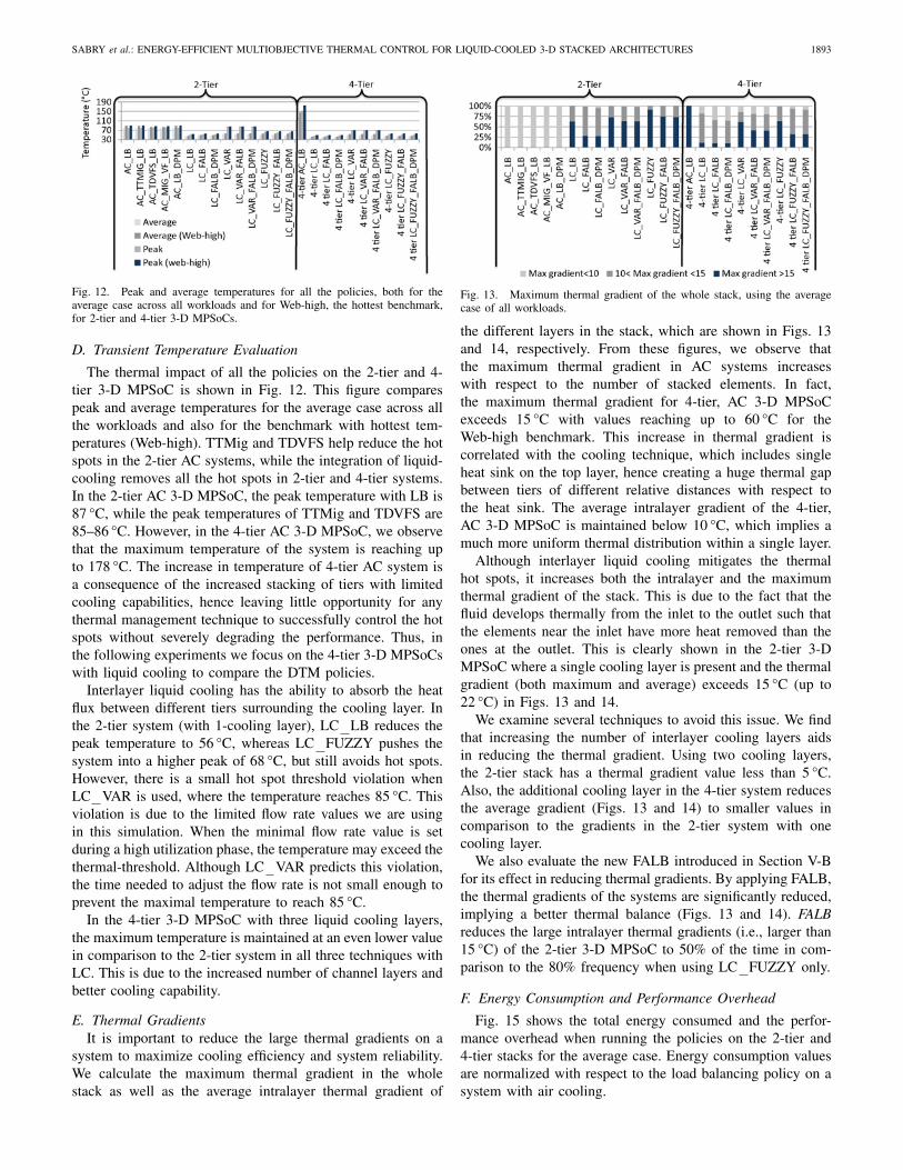
Fig. 12. Peak and average temperatures for all the policies, both for theaverage case across all workloads and for Web-high, the hottest benchmark,for 2-tier and 4-tier 3-D MPSoCs.
D. Transient Temperature Evaluation
The thermal impact of all the policies on the 2-tier and 4-tier 3-D MPSoC is shown in Fig. 12. This figure comparespeak and average temperatures for the average case across allthe workloads and also for the benchmark with hottest tem-peratures (Web-high). TTMig and TDVFS help reduce the hotspots in the 2-tier AC systems, while the integration of liquid-cooling removes all the hot spots in 2-tier and 4-tier systems.In the 2-tier AC 3-D MPSoC, the peak temperature with LB is87 °C, while the peak temperatures of TTMig and TDVFS are85–86 °C. However, in the 4-tier AC 3-D MPSoC, we observethat the maximum temperature of the system is reaching upto 178 °C. The increase in temperature of 4-tier AC system isa consequence of the increased stacking of tiers with limitedcooling capabilities, hence leaving little opportunity for anythermal management technique to successfully control the hotspots without severely degrading the performance. Thus, inthe following experiments we focus on the 4-tier 3-D MPSoCswith liquid cooling to compare the DTM policies.
Interlayer liquid cooling has the ability to absorb the heatflux between different tiers surrounding the cooling layer. Inthe 2-tier system (with 1-cooling layer), LC LB reduces thepeak temperature to 56 °C, whereas LC FUZZY pushes thesystem into a higher peak of 68 °C, but still avoids hot spots.However, there is a small hot spot threshold violation whenLC VAR is used, where the temperature reaches 85 °C. Thisviolation is due to the limited flow rate values we are usingin this simulation. When the minimal flow rate value is setduring a high utilization phase, the temperature may exceed thethermal-threshold. Although LC VAR predicts this violation,the time needed to adjust the flow rate is not small enough toprevent the maximal temperature to reach 85 °C.
In the 4-tier 3-D MPSoC with three liquid cooling layers,the maximum temperature is maintained at an even lower valuein comparison to the 2-tier system in all three techniques withLC. This is due to the increased number of channel layers andbetter cooling capability.
E. Thermal GradientsIt is important to reduce the large thermal gradients on a
system to maximize cooling efficiency and system reliability.We calculate the maximum thermal gradient in the wholestack as well as the average intralayer thermal gradient of
Fig. 13. Maximum thermal gradient of the whole stack, using the averagecase of all workloads.
the different layers in the stack, which are shown in Figs. 13and 14, respectively. From these figures, we observe thatthe maximum thermal gradient in AC systems increaseswith respect to the number of stacked elements. In fact,the maximum thermal gradient for 4-tier, AC 3-D MPSoCexceeds 15 °C with values reaching up to 60 °C for theWeb-high benchmark. This increase in thermal gradient iscorrelated with the cooling technique, which includes singleheat sink on the top layer, hence creating a huge thermal gapbetween tiers of different relative distances with respect tothe heat sink. The average intralayer gradient of the 4-tier,AC 3-D MPSoC is maintained below 10 °C, which implies amuch more uniform thermal distribution within a single layer.
Although interlayer liquid cooling mitigates the thermalhot spots, it increases both the intralayer and the maximumthermal gradient of the stack. This is due to the fact that thefluid develops thermally from the inlet to the outlet such thatthe elements near the inlet have more heat removed than theones at the outlet. This is clearly shown in the 2-tier 3-DMPSoC where a single cooling layer is present and the thermalgradient (both maximum and average) exceeds 15 °C (up to22 °C) in Figs. 13 and 14.
We examine several techniques to avoid this issue. We findthat increasing the number of interlayer cooling layers aidsin reducing the thermal gradient. Using two cooling layers,the 2-tier stack has a thermal gradient value less than 5 °C.Also, the additional cooling layer in the 4-tier system reducesthe average gradient (Figs. 13 and 14) to smaller values incomparison to the gradients in the 2-tier system with onecooling layer.
We also evaluate the new FALB introduced in Section V-Bfor its effect in reducing thermal gradients. By applying FALB,the thermal gradients of the systems are significantly reduced,implying a better thermal balance (Figs. 13 and 14). FALBreduces the large intralayer thermal gradients (i.e., larger than15 °C) of the 2-tier 3-D MPSoC to 50% of the time in com-parison to the 80% frequency when using LC FUZZY only.
F. Energy Consumption and Performance Overhead
Fig. 15 shows the total energy consumed and the perfor-mance overhead when running the policies on the 2-tier and4-tier stacks for the average case. Energy consumption valuesare normalized with respect to the load balancing policy on asystem with air cooling.

1894 IEEE TRANSACTIONS ON COMPUTER-AIDED DESIGN OF INTEGRATED CIRCUITS AND SYSTEMS, VOL. 30, NO. 12, DECEMBER 2011
Fig. 14. Average intra-layer thermal gradient of the whole stack, using theaverage case of all workloads.
Note that in LC LB case, only a single flow rate is used.Thus, there is no need for control valves to alter the flowrate. Therefore, in our energy consumption computation, wecalculate the cooling energy in LC LB as the pumping poweronly, without any valve power.
The fuzzy controller achieves major reductions in boththe coolant and the overall system energy consumption:LC FUZZY reduces the system energy (2-tier 3-D MPSoC)by 10.3% and 9.5%, as well as the cooling energy by 35% and26% at average workloads in comparison to LC VAR andLC LB, respectively. The reason LC FUZZY outperformsall other techniques in energy savings is due to the jointcontrol of flow rate and DVFS at run-time based on each core’sthermal and utilization status. At lower utilization levels andlower temperatures, the integrated system leaks less energythan that of a higher thermal profile.
Our fuzzy controller reduces energy consumption whilemaintaining the thermal benefits of liquid cooling. In the 4-tier case, LC FUZZY achieves 27% and 8% average coolantand overall system energy savings with respect to LC VAR.Moreover, LC FUZZY achieves 63% and 21% peak savingsin comparison to LC LB, as well as 45% and 18% peak sav-ings in comparison with LC VAR. The substantial increase inenergy savings with respect to the 2-tier system is due to thehigher number of cavities in the stack. With LC LB and threeexisting cavities (as in Fig. 1), a flow rate of 3 × 0.0323 l/minis required for the whole 3-D MPSoC, which in turn increasesthe required cooling power. However, with LC FUZZY andthree cavities, the flow rate can be lowered to minimal valueswhile allowing higher workload utilization than that of 2-tier 3-D MPSoC. This is due to the fact that the increasednumber of cavities enhances the interlayer cooling capabilities,as discussed earlier. Thus, more heat flux is absorbed fromdifferent directions leading to lower temperatures.
Finally, we explore the benefits of DPM to reducethe system energy. Fig. 15 shows that the benefits wegain from using DPM with LC FUZZY and FALB(LC FUZZY FALB DPM) are very minute with respect toLC FUZZY FALB. In fact, the average savings achieved byDPM is 1%, while the maximum savings reaches 5% withMPlayer benchmark.
For our multicore 3-D MPSoCs, we compute throughputas the performance metric. The performance degradation ofthe average workload under a set of policies is shown in
Fig. 15. Left axis shows the energy consumption in the whole system (chipand cooling network) for average workload, per stack. The right axis showsthe % delay for each policy. Note that air cooling also includes fan powerconsumption, which is not included in the figure.
Fig. 16. Layout of the adjusted floorplan used in 4-tier 3-D MPSoCs.
TABLE VI
Maximum Temperature and Thermal Gradients of 4-Tier 3-D
MPSoC with Different Floorplans
Floorplan in Fig. 1 Floorplan in Fig. 16
Flow Rate Max Intertier Max Max Intertier Maxml/min Temp Gradient Gradient Temp Gradient Gradient
°C °C/cm °C/cm °C °C/cm °C/cm
32 55.65 16.06 20.78 49.59 3.3 4.85
24 62.92 21.49 27.02 53.72 4.26 6.1643
16 78.31 31.4 38.47 64.2 9.89 11.63
8 124.2 62 73.12 84.51 19.82 21.63
Fig. 15. Liquid cooling-based systems do not suffer fromany performance degradation since the temperature of suchsystems does not rise to a value where another thermal man-agement technique should be applied. Although LC FUZZYuses DVFS, we apply DVFS based on the core utilization,hence the performance degradation does not exceed 0.01%,which is negligible in comparison to the degradation observedin the air-cooling scenarios.
G. Design Considerations for 3-D MPSoCs
We have shown in our previous results that in the 4-tier 3-D MPSoC case, the maximum temperature is kept below thethermal threshold (85 °C). However, the maximum temperatureis 49 °C, which shows that the system is thermally over-designed. Thus, in this section we show different design-timeparameters we may use to further optimize the 3-D stacks.This design-space exploration uses LC LB; however, sameprinciples can also be applied in conjunction with the otherDTM policies.
First, we reduce the maximum pumping flow rate to pushthe maximum temperature toward the thermal threshold. Wereduce the flow rate and observe the peak temperature, as wellas the intertier and maximum thermal gradients of the 4-tier

SABRY et al.: ENERGY-EFFICIENT MULTIOBJECTIVE THERMAL CONTROL FOR LIQUID-COOLED 3-D STACKED ARCHITECTURES 1895
3-D MPSoC, when operating with the maximum workloadrequirements (Web-high), as shown in first column in Table VI.This table shows that a higher temperature is reached whenthe injected flow rate is reduced. However, this increase isalso accompanied by an increase in the thermal gradient.These large thermal gradients are not preferable for the systemoperation, since large variations in thermal stress amongdifferent processing components lead to different degradationrates [9]. Therefore, solely reducing the maximum flow rateis an inadequate solution to push the operating temperature ofthe system near the thermal threshold as it may cause perfor-mance, reliability, or design challenges due to larger gradients.
Second, we investigate adjusting the floorplan to accountfor thermal properties of fluid flow. Using the results of Sec-tion V-A, we adjust the floorplan of the 3-D MPSoC by placingthe elements with higher power elements (cores) near the fluidinlet, while allocating the lower power units (L2 caches) nearthe fluid outlet port. Thus, we change the floorplan from tiersA and B shown in Fig. 1 to tier D shown in Fig. 16.
We again reduce the flow rate for the new layout, and weobserve a significant reduction in the thermal gradient withrespect to the floorplan in Fig. 1, as shown in Table VI. Thereason is the following: as the fluid is developing thermallyacross the channels, the thermal flux is decreasing closer to thefluid outlet port. This decrease in heat flux matches the coolingcapabilities of the fluid at that point (near the outlet), thus thejunction temperature of these elements is not increased. Thisbehavior indicates that the fluid flow characteristics can beexploited in thermally aware floorplanning of 3-D MPSoCs,which opens up new research directions for designing 3-DMPSoCs with interlayer liquid cooling.
VIII. Conclusion
In this paper, we have presented a novel design-time/run-time thermal management strategy for 3-D MPSoCs in-cluding active cooling. We performed a design-time thermalresponse analysis of 3-D MPSoC varying the liquid flow rate,applying DVFS, and applying various workload utilization sce-narios. We utilized this analysis in building a novel fuzzy con-troller that adjusted the liquid flow rate and the VF settings tobalance temperature across the 3-D stack and to minimize sys-tem energy consumption while preventing thermal hot spots.We implemented a large set of thermal management strategiessuch as temperature-aware load balancing and dynamic powermanagement in conjunction with our proposed controller. Ourexperimental results with 2-tier and 4-tier 3-D MPSoC casestudies illustrated that our fuzzy controller maintained thetemperature below the desired levels. At the same time, thecontroller reduced cooling energy by up to 63% and 45%, andsystem-level energy by up to 21% and 18% in comparison tosetting the highest coolant flow rate to match the worst-casetemperature and in comparison to using a state-of-the-art 3-DMPSoC thermal management approach, respectively.
References
[1] D. Atienza, P. G. Del Valle, G. Paci, F. Poletti, L. Benini, G. De Micheli,and J. M. Mendias, “A fast HW/SW FPGA-based thermal emulationframework for multi-processor system-on-chip,” in Proc. DAC, 2006,pp. 618–623.
[2] D. Atienza, P. G. Del Valle, G. Paci, F. Poletti, L. Benini, G. De Micheli,J. M. Mendias, and R. Hermida, “HW/SW emulation framework fortemperature-aware design in MPSoCs,” IEEE Trans. Design Automat.Electron. Syst., vol. 12, no. 3, pp. 1–26, Aug. 2007.
[3] M. S. Bakir, C. King, D. Sekar, H. Thacker, B. Dang, G. Huang, A.Naeemi, and J. D. Meindl, “3D heterogeneous integrated systems: Liquidcooling, power delivery, and implementation,” in Proc. CICC, Sep. 2008,pp. 663–670.
[4] X. Ban, X. Z. Gao, X. Huang, and A. V. Vasilakos, “Stability analysis ofthe simplest Takagi-Sugeno fuzzy control system using circle criterion,”Inform. Sci., vol. 177, no. 20, pp. 4387–4409, 2007.
[5] P. Bose, “Power-efficient microarchitectural choices at the early designstage,” in Proc. PACS (Keynote Address), 2003.
[6] T. Brunschwiler, H. Rothuizen, M. Fabbri, U. Kloter, B. Michel, R. J.Bezama, and G. Natarajan, “Direct liquid-jet impingement cooling withmicron-sized nozzle array and distributed return architecture,” in Proc.ITHERM, 2006, pp. 196–203.
[7] T. Brunschwiler, B. Michel, H. Rothuizen, U. Kloter, B. Wunderle, H.Oppermann, and H. Reichl, “Interlayer cooling potential in verticallyintegrated packages,” Microsyst. Technol., vol. 15, no. 1, pp. 57–74,2009.
[8] A. K. Coskun, J. Ayala, D. Atienza, and T. S. Rosing, “Modeling anddynamic management of 3D multicore systems with liquid cooling,” inProc. VLSI-SoC, 2009, pp. 60–65.
[9] A. K. Coskun, J. L. Ayala, D. Atienza, T. S. Rosing, and Y. Leblebici,“Dynamic thermal management in 3D multicore architectures,” in Proc.DATE, 2009, pp. 1410–1415.
[10] A. K. Coskun, D. Atienza, T. S. Rosing, T. Brunschwiler, and B.Michel, “Energy-efficient variable-flow liquid cooling in 3D stackedarchitectures,” in Proc. DATE, Mar. 2010, pp. 111–116.
[11] A. K. Coskun, T. S. Rosing, and K. Gross, “Utilizing predictors forefficient thermal management in multiprocessor SoCs,” IEEE Trans.Comput.-Aided Des., vol. 28, no. 10, pp. 1503–1516, Oct. 2009.
[12] A. K. Coskun, T. S. Rosing, and K. Whisnant, “Temperature aware taskscheduling in MPSoCs,” in Proc. DATE, 2007, pp. 1659–1664.
[13] Y. Diao, J. L. Hellerstein, A. J. Storm, M. Surendra, S. Light-stone, S. Parekh, and C. Garcia-Arellano, “Using MIMO linear con-trol for load balancing in computing systems,” in Proc. ACC, 2004,pp. 2045–2050.
[14] J. Donald and M. Martonosi, “Techniques for multicore thermalmanagement: Classification and new exploration,” in Proc. ISCA, 2006,pp. 78–88.
[15] Z. Feng and P. Li, “Fast thermal analysis on GPU for 3D-ICs withintegrated microchannel cooling,” in Proc. ICCAD, 2010, pp. 551–555.
[16] M. Healy, M. Vittes, M. Ekpanyapong, C. S. Ballapuram, S. K. Lim, H.S. Lee, and G. H. Loh, “Multiobjective microarchitectural floorplanningfor 2-D and 3-D ICs,” IEEE Trans. Comput.-Aided Design, vol. 26, no.1, pp. 38–52, Jan. 2007.
[17] W.-L. Hung, G. M. Link, Y. Xie, N. Vijaykrishnan, amd M. J. Irwin,“Interconnect and thermal-aware floorplanning for 3D microprocessors,”in Proc. ISQED, 2006, pp. 98–104.
[18] Y. J. Kim, Y. K. Joshi, A. G. Fedorov, Y.-J. Lee, and S.-K. Lim,“Thermal characterization of interlayer microfluidic cooling of three-dimensional integrated circuits with nonuniform heat flux,” J. HeatTransfer, vol. 132, no. 4, pp. 1–9, 2010.
[19] C. R. King, D. Sekar, M. S. Bakir, B. Dang, J. Pikarsky, and J. D.Meindl, “3D stacking of chips with electrical and microfluidic I/Ointerconnects,” in Proc. ECTC, 2008, pp. 1–7.
[20] Y. J. Lee, R. Goel, and S. K. Lim, “Multi-functional interconnectcooptimization for fast and reliable 3D stacked ICs,” in Proc. ICCAD,2009, pp. 645–651.
[21] A. Leon, J. L. Shin, K. W. Tam, W. Bryg, F. Schumacher, P.Kongetira, D. Weisner, and A. Strong, “A power-efficient high-throughput 32-thread SPARC processor,” in Proc. ISSCC, Feb. 2006,pp. 295–304.
[22] Z. Li, X. Hong, Q. Zhou, S. Zeng, J. Bian, H. Yang, V. Pitchumani,and C.-K. Cheng, “Integrating dynamic thermal via planning with 3Dfloorplanning algorithm,” in Proc. ISPD, 2006, pp. 178–185.
[23] K. Matsumoto, S. Ibaraki, M. Sato, K. Sakuma, Y. Orii, and F. Yamada,“Investigations of cooling solutions for three-dimensional (3D) chipstacks,” in Proc. SEMI-THERM, 2010, pp. 25–32.
[24] R. McDougall, J. Mauro, and B. Gregg, Solaris Performance and Tools.Englewood Cliffs, NJ: Sun Microsystems Press/Prentice-Hall, 2006.
[25] F. Mulas, D. Atienza, A. Acquaviva, S. Carta, L. Benini, and G.De Micheli, “Thermal balancing policy for multiprocessor streamcomputing platforms,” IEEE Trans. Comput.-Aided Design, vol. 28, no.12, pp. 1870–1882, Dec. 2009.

1896 IEEE TRANSACTIONS ON COMPUTER-AIDED DESIGN OF INTEGRATED CIRCUITS AND SYSTEMS, VOL. 30, NO. 12, DECEMBER 2011
[26] H. T. Nguyen and N. R. Prasad, Fuzzy Modeling and Control, SelectedWorks of M. Sugeno. Boca Raton, FL: CRC Press, 1999.
[27] L. D. Paulson, “IBM supercomputers heat will warm universitystructures,” Computer, vol. 42, no. 9, pp. 18–21, Sep. 2009.
[28] K. Puttaswamy and G. H. Loh, “Thermal analysis of a 3D die-stackedhigh-performance microprocessor,” in Proc. GLSVLSI, 2006, pp. 19–24.
[29] H. Qian, X. Huang, H. Yu, and C. Chang, “Cyber-physical thermalmanagement of 3D multi-core cache-processor system with microfluidiccooling,” ASP J. Low Power Electron., vol. 7, no. 1, pp. 1–12, 2011.
[30] M. M. Sabry, A. K. Coskun, and D. Atienza, “Fuzzy control forenforcing energy efficiency in high-performance 3D systems,” in Proc.ICCAD, 2010, pp. 642–648.
[31] WILO MHIE Centrifugal Pump [Online]. Available: http://www.wilo.com/cps/rde/xchg/en/layout.xsl/3707.htm
[32] Festo Electric Automation Technology [Online]. Available: http://www.festodidactic.com/ov3/media/customers/1100/0096636000107522-3683.pdf
[33] K. Skadron, M. R. Stan, W. Huang, S. Velusamy, K. Sankaranarayanan,and D. Tarjan, “Temperature-aware microarchitecture,” in Proc. ISCA,Jun. 2003, pp. 2–13.
[34] A. Sridhar, A. Vincenzi, M. Ruggiero, T. Brunschwiler, and D.Atienza, “3D-ICE: Fast compact transient thermal modeling for3D-ICs with inter-tier liquid cooling,” in Proc. ICCAD, 2010,pp. 463–470.
[35] A. Sridhar, A. Vincenzi, M. Ruggiero, T. Brunschwiler, D. A. Alonso,“Compact transient thermal model for 3D ICs with liquid cooling viaenhanced heat transfer cavity geometries,” in Proc. THERMINIC, 2010,pp. 1–6.
[36] H. Su, F. Liu, A. Devgan, E. Acar, and S. Nassif, “Full-chip leakageestimation considering power supply and temperature variations,” inProc. ISLPED, 2003, pp. 78–83.
[37] M. Su and H. Chang, “Application of neural networks incorporatedwith real-valued genetic algorithms in knowledge acquisition,” FuzzySets Syst., vol. 112, no. 1, pp. 85–97, 2000.
[38] T. Takagi and M. Sugeno, “Fuzzy identification of systems and itsapplications to modeling and control,” IEEE Trans. Syst., Man, Cybern.,vol. 15, no. 1, pp. 116–132, Feb. 1985.
[39] K. Tanaka and M. Sugeno, “Stability analysis and design of fuzzycontrol systems,” Fuzzy Sets Syst., vol. 45, no. 2, pp. 135–156, 1992.
[40] D. Tarjan, S. Thoziyoor, and N. P. Jouppi, CACTI 4.0, HP Laboratories,Palo Alto, CA, Tech. Rep. HPL-2006-86, 2006.
[41] D. B. Tuckerman and R. F. W. Pease, “High-performance heat sinkingfor VLSI,” IEEE Electron Device Lett., vol. 2, no. 5, pp. 126–129, May1981.
[42] L.-X. Wang, “Stable and optimal fuzzy control of linear systems,”IEEE Trans. Fuzzy Syst., vol. 6, no. 1, pp. 137–143, Feb. 1998.
[43] F. Zanini, D. Atienza, G. De Micheli, and S. P. Boyd, “Online convexoptimization-based algorithm for thermal management of MPSoCs,” inProc. GLSVLSI, 2010, pp. 203–208.
[44] X. Zhou, Y. Xu, Y. Du, Y. Zhang, and J. Yang, “Thermal managementfor 3D processors via task scheduling,” in Proc. ICPP, Sep. 2008, pp.115–122.
[45] C. Zhu, G. Zhenyu, L. Shang, R. P. Dick, and R. Joseph, “Three-dimensional chip-multiprocessor run-time thermal management,” IEEETrans. Comput.-Aided Design, vol. 27, no. 8, pp. 1479–1492, Aug. 2008.
Mohamed M. Sabry (S’12) received the B.S.(summa cum laude) and M.S. degrees in electri-cal engineering from Ain Shams University, Cairo,Egypt in 2005 and 2008, respectively. He is currentlypursuing the Ph.D. degree in electrical engineer-ing with the Department of Electrical Engineering,École Polytechnique Federale de Lausanne, Lau-sanne, Switzerland.
He is a member of the Embedded Systems Lab-oratory, École Polytechnique Federale de Lausanne.His current research interests include system design
and resource management methodologies in embedded systems, and multi-processor system-on-chips (MPSoCs), especially temperature and reliabilitymanagement of 2-D and 3-D MPSoCs.
Mr. Sabry was the recipient of the Best Student Award when he was pursuingthe B.S. degree.
Ayse K. Coskun (M’06) received the M.S. andPh.D. degrees in computer science and engineeringfrom the University of California at San Diego, SanDiego.
She is currently an Assistant Professor with theDepartment of Electrical and Computer Engineering,Boston University (BU), Boston, MA. She was withSun Microsystems (now Oracle), San Diego, forthree years prior to her current position at BU. Hercurrent research interests include energy-efficientcomputing, multicore systems, 3-D stack architec-
tures, computer architecture, and embedded systems and software.Dr. Coskun received the Best Paper Award at IFIP/IEEE VLSI-SoC Con-
ference in 2009. She currently serves on the program committees of manydesign automation conferences including DATE, GLSVLSI, and VLSISoC.She is a member of the ACM.
David Atienza (M’05) received the M.S. de-gree from the Complutense University of Madrid,Madrid, Spain, and the Ph.D. degree from the Inter-University Microelectronics Center, Leuven, Bel-gium, in 2001 and 2005, respectively, both in com-puter science and engineering.
He is currently a Professor of electrical engi-neering and the Director of the Embedded SystemsLaboratory, École Polytechnique Fédérale de Lau-sanne, Lausanne, Switzerland. His current researchinterests include system-level design methodologies
for high-performance multiprocessor system-on-chip (MPSoC) and embeddedsystems, including new 2-D/3-D thermal-aware design for MPSoCs, wirelessbody sensor networks, HW/SW reconfigurable systems, dynamic memoryoptimizations, and network-on-chip design. He is a co-author of more than 150publications in peer-reviewed international journals and conferences, severalbook chapters, and two U.S. patents in these fields.
Dr. Atienza has received a Best Paper Award at the VLSI-SoC 2009conference, and three Best Paper Award Nominations at the WEHA-HPCS2010, ICCAD 2006, and DAC 2004 conferences. He is an Associate Editor ofthe IEEE Transactions on Computer-Aided Design of Circuits and
Systems, and Integration (Elsevier). Since 2008, he has been a member ofthe Executive Committee of the IEEE Council on EDA, and since 2010, amember of the Board of Governors of the IEEE Circuits and Systems Society.
Tajana Simunic Rosing (M’01) received the M.S.degree in electrical engineering from the Universityof Arizona, Tucson, where her thesis topic was high-speed interconnect and driver-receiver circuit design,and the Ph.D. degree from Stanford University, PaloAlto, CA, in 2001, concurrently with completingthe Masters degree in engineering management. HerPh.D. topic was dynamic management of powerconsumption.
Prior to pursuing the Ph.D. degree, she was aSenior Design Engineer with Altera Corporation,
San Jose, CA. She is currently an Associate Professor with the ComputerScience Department, University of California at San Diego, San Diego. Priorto this, she was a full-time Researcher with HP Laboratories, Palo Alto, CA,while working part-time at Stanford University. With Stanford University,she has been involved with leading research of a number of graduate studentsand has taught graduate level classes. Her current research interests includeenergy efficient computing, and embedded and wireless systems.
Dr. Rosing has served at a number of technical paper committees, andis currently an Associate Editor of the IEEE Transactions on Mobile
Computing.
Thomas Brunschwiler (M’10) received the Bach-elors and Masters degrees from the NTB BuchsUniversity of Applied Sciences and Technology,Buchs, Switzerland, in microsystem technology. Heis currently completing the Ph.D. degree in electricalengineering from the Technical University of Berlin,Berlin, Germany.
Since 2001, he has been with the IBM ZurichResearch Laboratory, Zurich, Switzerland, where hehas developed integrated optical devices and ex-plored organic light emitting diodes. He is currently
a member of the Advanced Thermal Packaging Team, IBM Zurich ResearchLaboratory. His current research interests include 3-D integration with respectto volumetric heat removal and power delivery, supporting performance, andefficiency scaling of high-end servers.