digital object identifier 10.1109/ojvt.2020.3036582 a
TRANSCRIPT
Received 14 September 2020; accepted 3 November 2020. Date of publication 6 November 2020;date of current version 2 December 2020. The review of this article was coordinated by Associate Editor A. Chin.
Digital Object Identifier 10.1109/OJVT.2020.3036582
A Review of Driving Simulation Technologyand Applications
LUCAS BRUCK 1 (Student Member, IEEE), BRUCE HAYCOCK2, AND ALI EMADI 1 (Fellow, IEEE)1 McMaster Automotive Resource Centre, McMaster University, Hamilton, ON L8P 0A6, Canada
2 Toronto Rehabilitation Institute, University of Toronto, Toronto, ON M5G 2A2, Canada
CORRESPONDING AUTHOR: LUCAS BRUCK (e-mail: [email protected]).
ABSTRACT Driving simulation has become a very useful tool for vehicle design and research in industryand educational institutes. This paper provides a review of driving simulator components, including thevehicle dynamics model, the motion system, and the virtual environment, and how they interact with thehuman perceptual system in order to create the illusion of the driving. In addition, a sample of currentstate-of-the-art vehicle simulators and algorithms are described. Finally, current applications are discussed,such as driver-centered studies, chassis and powertrain design, and autonomous systems development.
INDEX TERMS Driver-in-the-loop, driving simulation, motion cueing, vehicle dynamics, vehicle simulator,virtual simulation.
I. INTRODUCTIONThe concept of simulation can be defined as the emulationof a specific behavior through a generic imitating system [1].In the automotive field, simulation is used both in academiafor research and in industry for design purposes. The reasonis that by using virtual simulation, new systems can be devel-oped and evaluated within lower time and with lower financialinvestment. In the automotive industry for instance, virtualsimulation can be used throughout all phases of developmentof a new vehicle. During virtual design, model-in-the-loopanalysis enables the comparison of different system architec-tures, e.g. comparison of powertrain topologies to evaluate thefuel consumption and emissions.
Virtual simulation also speeds the testing phase. Structural,fluid dynamics, and multibody simulation not only optimizethe characteristics and geometry of the components, but alsowork as filters for component selection, e.g. definition ofspring pre-load and shock absorber dynamic curve in suspen-sion tuning. Without virtual simulation, not only would thedevelopment cost increase, but also the timeframe needed toaccomplish each step of development would be longer. Duringcalibration of on-board software parameters or performancecomponents, virtual simulation reduces the number of proto-types that will eventually be manufactured for testing. In thisway, the design process as we know it today, with rapid releaseof new products, is only possible due to simulation. Within
the various types of vehicle simulation, the ability to imitate aground vehicles response in real time given real driver inputsis called driving simulation and it relies on virtual cues to trickhuman perception and create the illusion of immersion andmotion in a controlled environment.
In the early 1910 s the first motion simulators begin toappear in England and France as a means to safely provideflight training [2]. Motion simulation technology would notbe restricted to flight training for long, however. It is notclear though which driving simulator was the first to appear,some researchers acknowledge the system designed in [3],published in 1934 but given the simple architecture of thistraffic simulator some authors prefer to point out later worksas the real beginning of relevant developments of drivingsimulators. During the 1970 s several 3 degree-of-freedom(DOF) driving simulators were developed by auto makers andresearch institutes as depicted in [1], such as the well-knowndevice designed by Volkswagen and another at the SwedishRoad and Traffic Research Institute. In addition, the pioneerwork to develop the Computer Generated Display Simulatorby General Motors together with the Virginia PolytechnicInstitute and State University from 1973 to 1975 is acknowl-edged in [4].
All previous attempts made significant contributions, but itwas in 1985 that Daimler-Benz came up with a 6-DOF hexa-pod motion system integrated to a vehicle dome [5] that would
This work is licensed under a Creative Commons Attribution 4.0 License. For more information, see https://creativecommons.org/licenses/by/4.0/
VOLUME 2, 2021 1
BRUCK ET AL.: REVIEW OF DRIVING SIMULATION TECHNOLOGY AND APPLICATIONS
be later accepted as the most common configuration of highlevel driving simulators around the globe. Rapid developmentof new graphic sources happened between the late 1990 s andearly 2000s [6]. Digital three-dimensional (3D) graphics, newdisplay resolution, and real-time graphic processing opened anew world of possibilities for driving simulators. The com-bination of various electronics improvements over the yearsmade the increasing fidelity of driving simulators possible.
Recent studies use driving simulation technology to assessenergy management strategies (EMS), human machine inter-faces (HMIs), active control systems (ACSs), advanced driverassistance systems (ADAS) and road planning. The purposeof the present work is to break down the mechanisms behindthe driving simulation technology, describing the main com-ponents of a driving simulator, as a guide for resource centersthat want to implement this technology. This work contributesto providing a comprehensive review of the past and currentstate-of-the-art technologies, driving simulator examples, andapplications. Former reviews of this kind can be found in [6],where a thorough survey of relevant simulators at that timewas conducted. In that review, the simulators are clusteredby their level of cost, a very common form of classification.Additional reviews were presented in [7], with example ap-plications in medicine and engineering, in [8], that detailsmotion system design, and in [9], where the focus is on theclassification.
The paper is organized as follows. Section II introducesthe human perceptual system. Section III explains the archi-tecture of driving simulators. It discusses each componentseparately, exposing current technologies and giving exam-ples. Section IV brings examples of driving simulators inresearch and industry. Section V discusses various applica-tions throughout automotive industry and research. Finally,Section VI concludes the work and state the prospects fordriving simulation.
II. HUMAN PERCEPTUAL SYSTEMSince the role of a driving simulator is to imitate driving inthe real world in order to deceive perception, it is important tounderstand how the human body perceives the driving experi-ence. In driving simulators, multiple systems are combined toform the self-motion perception as further detailed. Becausedriving is primarily a visual task, one of the most importanthuman sensors to be accounted for in driving simulation isthe visual system. In fact, the visual system accounts for themajority of motion perception in a three-dimensional environ-ment [10]. The optical flow together with visual direction andextra-retinal direction form the visual information to be inter-preted by the brain in order to define heading [11]. Althoughless important than the visual system, the auditory systemcan also be classified as a self-motion perceptual system. It isproven in [12] that through audio means only, separate fromother sensory systems, individuals are able to identify, withcertain precision, the time-to-collision of sources of noise.Interesting research is conducted in [13] where the authors
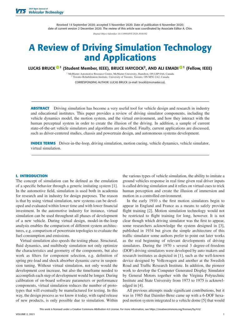
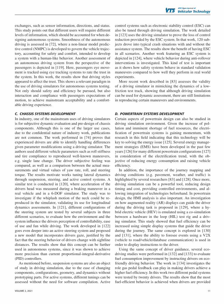
FIGURE 1. Human vestibular system [17].
concluded that adding auditory cues to visual cues increasesthe illusion of motion.
While in static simulators the visual and auditory systemsare responsible for all motion perception, in motion simula-tors other body sensors are also engaged to build the driv-ing experience. The somatosensory system is responsible forall tactile perceptions and proprioceptive sensors [11], theformer accounting for force changes due to motion and thelast accounting for position perception and accelerations. Asproposed by [14], it is possible to create an illusion of motionby vibrating postural muscles. Therefore, the better the cabinmimics the actual environment of a vehicle cockpit (e.g. byrepresenting with fidelity the internal components, dashboard,seats, texture, commands, and pedals) as well as faithfully rep-resenting the vibration and the friction resistance for movingeach component, the more realistic the driving experience.
The vestibular system is an inner ear complex comprisingsemi-circular canals and otolith organs, to recognize linearas well as angular motion [9]. As detailed in [15], the semi-circular canals consist in three circular cavities filled with afluid (endolymph) that deflect hair lining the canals when anangular acceleration is experienced, such as when the indi-vidual is nodding or tilting their head left to right, with anoutput proportional to angular velocity. The otolith organs, onthe other hand are made by the combination of small sacs ofsensitive hairs. The role of the sensitive hairs is to sense linearacceleration as well as gravitational forces and transmit it tothe central nervous systems. The utricle detects the motion inthe horizontal plane, while the saccule detects it in the verticalplane. A representation of the inner ear organs is depicted inFig. 1. An example of modelling the visual-vestibular systemwas presented in [16], showing how drivers make use of thevestibular system to determine steering angle. Furthermore,this work provides evidence that drivers adapt depending onhow those cues are given.
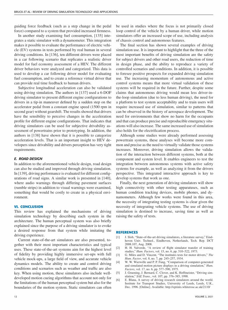
III. ARCHITECTUREAs mentioned before, the goal of a driving simulator is tocreate an illusion of the driving experience. To accomplishthat, different systems are combined. The diagram depicted inFig. 2 shows not only the interdependence between each sub-system but also how driver and vehicle model are in the centerof the process. Driver input is used to calculate the vehicle
2 VOLUME 2, 2021

FIGURE 2. Diagram of a driving simulator.
dynamics by the vehicle model, which will be used by thefeedback systems to give the driver the necessary cues. Thescenario control uses the definitions of environment (terrain),and the vehicle dynamics to output visual and sound cues.In simulators where multiple projectors are used to createa seamless image typically projected onto curved screens,the warping and blending of the image must be done beforeprojection. Haptic feedback such as steering torque, activeseats and belts is also used to provide cues from the vehicledynamics.
The green path in Fig. 2 shows optional systems in thesequence for providing motion in driving simulators. Thiscan improve the immersion considerably, and better allow forexperiments examining the dynamics of the vehicles such asfor the development of active systems. In motion simulators,the motion cueing algorithm will take the vehicle response anddetermine how to move the motion system accounting for thekinematics of that system, be transformed into actuator com-mands by the kinematics of the machine, and then producedby the motion system providing cueing to the human driver.
A. VEHICLE DYNAMICS MODELThe definition of model is presented in [18] as a simplifiedsystem that reproduces the characteristics of a more complex
structure or organism. In vehicle simulation, often third-partysoftware is dedicated to the vehicle dynamics model. Thismodel must contain a mathematical representation of the ve-hicle subsystems (i.e. body frame, suspension, tires, brakes,steering and powertrain) [19] and it must be able to computethe dynamic behavior relative to a fixed global orientationsystem, calculating component forces and non-linearities [20].Furthermore, driver-in-the-loop simulation applications re-quire the vehicle models to be calculated within the availabletime step, without losing accuracy [6].
A simple way to represent vehicle motion is through thequarter car model detailed in [21] that isolates the analysisby focusing on the motion and forces of a single wheel.Although this model is helpful to understand wheel dynam-ics, it does not represent all motion available in a vehicle.The single-track model and the linear roll model add lat-eral dynamics and roll dynamics respectively [20], still thosemodels do not account for the minimum necessary motionto fully reproduce driving experience. The twin-track model(TTM) is the simplest model that can support the needs ofa full motion driving simulator [20]. The TTM without theKinematic Wheel Suspension (KWS) model has 14-DOF, i.e.it models the translational and rotational motion around thelongitudinal, lateral and vertical axes (x, y, and z), the rotationof the wheels, and the vertical motion of each wheel individ-ually. Considering the full motion of the wheel suspensionand steering components the twin-track model can describethe vehicle motion accounting for 30-DOF. Since multibodysystem approach is based on the relationship between rigidbodies and joints as subsystems, it is considered ideal formechanical systems simulation. Therefore, the most commonvehicle dynamics software are multibody solutions. In addi-tion, an important characteristic these days is co-simulationwith a third-party software, which enables the assessmentof several advanced control systems such as electric powersteering, electronic stability control, and powertrain controlsystems [18]. Furthermore, by being able to interact withother vehicle systems modules the driving simulator becomesa platform for hardware-in-the-loop simulation and validationof those systems.
B. SCENARIO DESIGNAnother key feature of driving simulator is the possibility ofcreating specific scenarios. In driving simulation, a scenariocan be described as an event that happens in a virtual environ-ment. The event can be a predefined situation, e.g. a pedestriancrossing in front of the ego vehicle, or a situation created bythe driver, e.g. a sine with dwell maneuver. In these examples,the environment is the terrain, road, signs, buildings, and otherobjects surrounding the ego vehicle. The scenarios are createdby varying the traffic, weather, and events in that environment.As described in [22], there are different methods to generatedriving scenarios and pre-defined trajectory of virtual vehiclesin order to simulate traffic. The trajectory of those vehicles canbe developed simply based on road geometry, imported datafrom other simulations, or through an interface that interacts
VOLUME 2, 2021 3
BRUCK ET AL.: REVIEW OF DRIVING SIMULATION TECHNOLOGY AND APPLICATIONS
with the driving simulator engine. The work developed in [23]instead builds a platform to co-simulate multiple driving sim-ulators, which increases the realism of the traffic scenario. Thestudy in [24] uses a traffic scenario to evaluate how trafficdensity affects overtaking and lane change maneuvers.
In [25] the scenario construction was focused on signsand roadside information warnings, instead of other vehicles.The idea was to measure how the rivers journey decision isaffected by the information available. Repeatability is veryimportant in early phase of development because engineerscan easily visualize the problems a certain system presentsin specific condition. Although possible to forecast, weatheris usually a limitation in vehicle testing, depending on whichregion the manufacturer testing center is located. In the caseprovided by [26] and [27], the low visibility in foggy situa-tions and the risk brought by this condition is evaluated.
C. VISUAL CUESOver the years, visual cues evolved from analog video pre-sentations and film to digital graphics. These digital graphicsrapidly improved from a low number of polygons to highcount textured and shaded polygons that provide a highly real-istic environment for use in driving simulation. In addition, theimprovement of projector technology with increasingly higherpixel resolution, brightness, and contrast ratio, made the accu-rate projection of such graphics possible [6]. On the contrary,these projectors have been used with similar front projectioncurved screens as presented in [28] since the 1970 s, whichhas only now begin to change in limited applications with theuse of head mounted devices (HMD). Even with the advent ofHMDs, projection screens are still preferable in most cases,as the limited field of view, image lag, and the obscuring ofthe vehicle interior limit the usefulness of this type of device.Nevertheless, a few authors explored the suitability of thesesystems in driving simulators in [29] and [30]. Although theyforesee an increase in the use of head-mounted devices, theyagree that screen-based projection systems still are preferableamong tested subjects since they give a better perception ofvelocity and surroundings.
In an attempt to enhance the visual cues, several authorspresent different add-on solutions to the conventional roundedscreens presented in the most advanced driving simulators.In [31] a visual scale factor is used in an attempt to enhancethe speed perception by changing the geometric field of view.In [32], the authors replaced a monoscopic projection systemwith a 3D-stereoscopic system for improved depth perception,to investigate the use of 3D projector for enhancing velocity aswell as distance judgement in a driving simulator. The passivestereoscopic 3D was achieved by using 10 projectors, oneprojector per eye for each one of the 5 channels for the forwardview. The masking is done through a wavelength multiplexprocess which requires filtering of the projector signals andfiltering glasses for the driver. The main drawbacks of suchsystem are the cost associated with the added complexity,the packaging of the projectors in the display structure, andthe potential for increased eyestrain and resulting simulator
sickness. By exposing subjects with attested regular stereopsisto a simple car following scenario, the authors were not able toprovide strong evidence of the improvements. Lastly in [33],a headlight glare system is created to help understanding howdriver performance with different populations is affected bythe glare of oncoming vehicles during night driving in ruralhighway scenarios.
Improvements in PC hardware for rendering virtual worldshas enabled the use of gaming engines in place of the pre-viously used custom rendering hardware. One widely usedsoftware package for rendering virtual environments in sim-ulators is OpenSceneGraph (OSG) [34]. Other products thathave gained momentum recently given their realistic render-ing are Unity [35] and Unreal Engine [36]. Realistic animationand vast object databases can highly improve immersion. Thework in [37] assesses how different the driver behavior givendifferent fidelity of visual systems. In that work, a low graphicfidelity simulator was compared to a high fidelity one builtwith the Unreal engine. The results show that visual attentionand situation awareness are highly impacted depending on thefidelity of the visual system. Given its ability to reproducerealistically external objects, Unreal can also be used as aplatform to train and test autonomous systems, as developedin [38].
D. AUDITORY CUESAs defined in [39], the importance of the audio cues is jus-tified by how it affects speed judgement, driver awareness,and fatigue. In fact, the audio impact on speed perception isdepicted in [40]. In this work, an experiment is conducted withsubjects of different age ranges (young and older adults) thatare exposed to driving tasks where visual cues to self-motionare provided while the respective presence/absence of audi-tory cues is manipulated. The conducted experiment provesthe assumption that auditory cues affect longitudinal motionperception (speed and acceleration), with older adults moresusceptible. Therefore, it is also important to have a well-designed audio library in order to provide quality congruentcues to the driver and maintain the immersion created by thevisual system.
Three-dimensional sound is the most suitable choice indriving simulation application [6] since the noise inside thecabin is a combination of noises from different sources, i.e.aerodynamics, tire interaction with the surface, and drive-line [9]. As explained in detail in [41], the majority of simula-tors use the wave table method which consists of lookup tablesthat receives input values from the sources in the simulationengine (e.g. road, powertrain, and wind sounds) and outputsinterpolated cues. In addition, the importance of low fre-quency speakers is also explained since interior cabin noisesare in this frequency range.
E. HAPTIC CUESThe control components (i.e. steering wheel and pedals) act asa bridge between human input and vehicle behavior, makingthem essential tools in vehicle dynamics feedback. For that
4 VOLUME 2, 2021
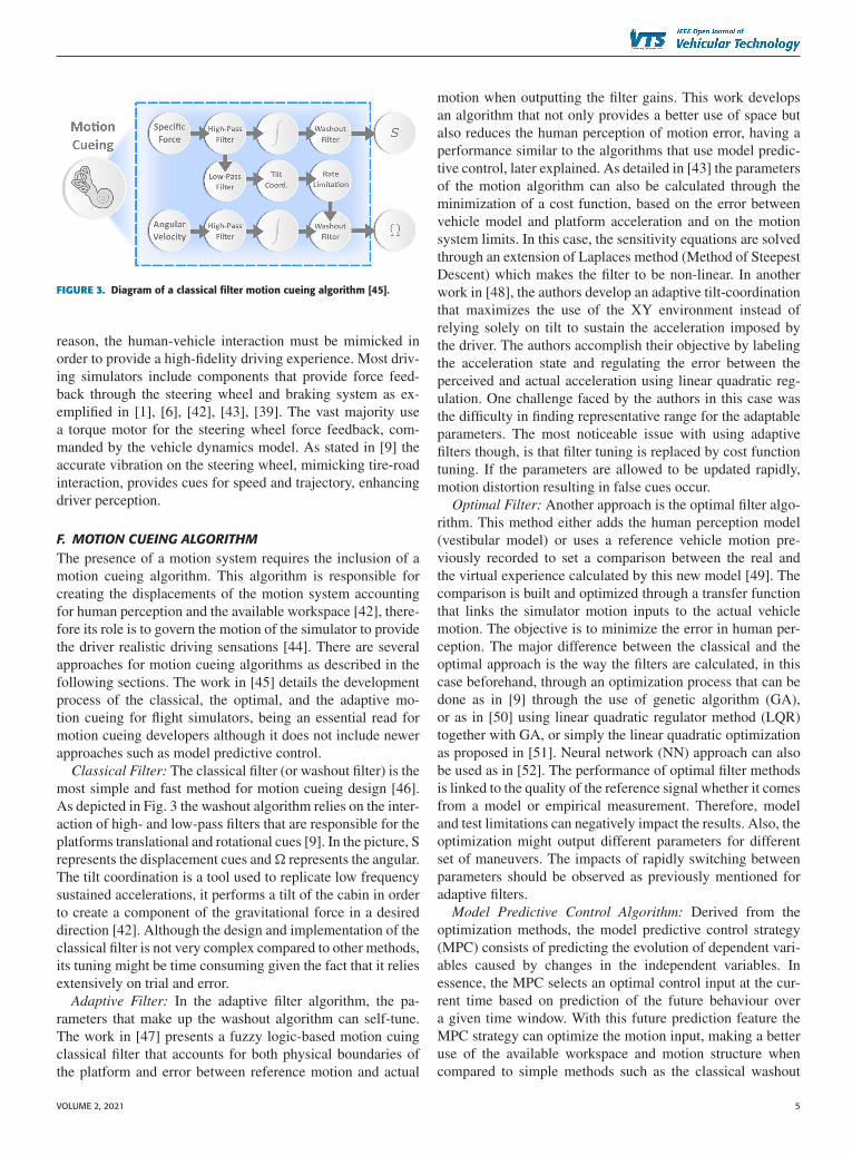
FIGURE 3. Diagram of a classical filter motion cueing algorithm [45].
reason, the human-vehicle interaction must be mimicked inorder to provide a high-fidelity driving experience. Most driv-ing simulators include components that provide force feed-back through the steering wheel and braking system as ex-emplified in [1], [6], [42], [43], [39]. The vast majority usea torque motor for the steering wheel force feedback, com-manded by the vehicle dynamics model. As stated in [9] theaccurate vibration on the steering wheel, mimicking tire-roadinteraction, provides cues for speed and trajectory, enhancingdriver perception.
F. MOTION CUEING ALGORITHMThe presence of a motion system requires the inclusion of amotion cueing algorithm. This algorithm is responsible forcreating the displacements of the motion system accountingfor human perception and the available workspace [42], there-fore its role is to govern the motion of the simulator to providethe driver realistic driving sensations [44]. There are severalapproaches for motion cueing algorithms as described in thefollowing sections. The work in [45] details the developmentprocess of the classical, the optimal, and the adaptive mo-tion cueing for flight simulators, being an essential read formotion cueing developers although it does not include newerapproaches such as model predictive control.
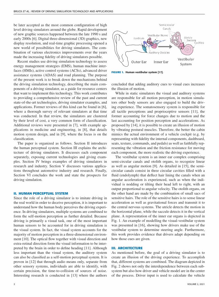
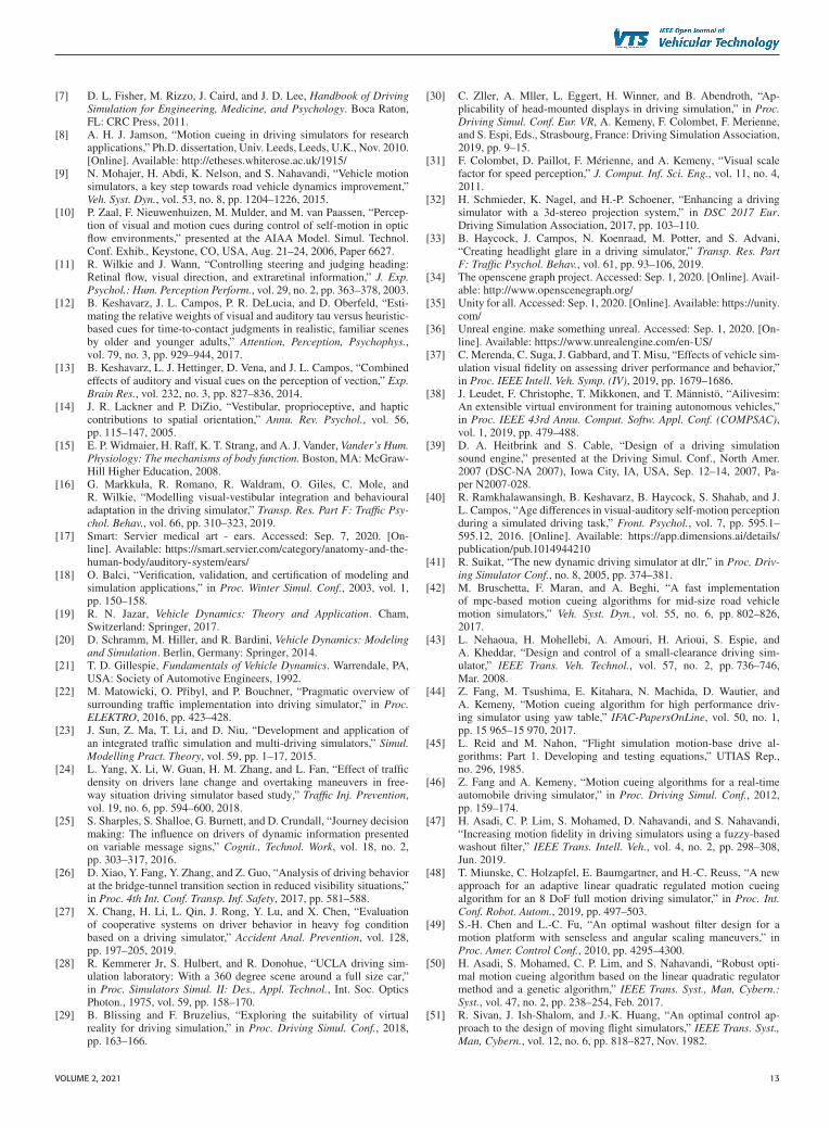
Classical Filter: The classical filter (or washout filter) is themost simple and fast method for motion cueing design [46].As depicted in Fig. 3 the washout algorithm relies on the inter-action of high- and low-pass filters that are responsible for theplatforms translational and rotational cues [9]. In the picture, Srepresents the displacement cues and � represents the angular.The tilt coordination is a tool used to replicate low frequencysustained accelerations, it performs a tilt of the cabin in orderto create a component of the gravitational force in a desireddirection [42]. Although the design and implementation of theclassical filter is not very complex compared to other methods,its tuning might be time consuming given the fact that it reliesextensively on trial and error.
Adaptive Filter: In the adaptive filter algorithm, the pa-rameters that make up the washout algorithm can self-tune.The work in [47] presents a fuzzy logic-based motion cuingclassical filter that accounts for both physical boundaries ofthe platform and error between reference motion and actual
motion when outputting the filter gains. This work developsan algorithm that not only provides a better use of space butalso reduces the human perception of motion error, having aperformance similar to the algorithms that use model predic-tive control, later explained. As detailed in [43] the parametersof the motion algorithm can also be calculated through theminimization of a cost function, based on the error betweenvehicle model and platform acceleration and on the motionsystem limits. In this case, the sensitivity equations are solvedthrough an extension of Laplaces method (Method of SteepestDescent) which makes the filter to be non-linear. In anotherwork in [48], the authors develop an adaptive tilt-coordinationthat maximizes the use of the XY environment instead ofrelying solely on tilt to sustain the acceleration imposed bythe driver. The authors accomplish their objective by labelingthe acceleration state and regulating the error between theperceived and actual acceleration using linear quadratic reg-ulation. One challenge faced by the authors in this case wasthe difficulty in finding representative range for the adaptableparameters. The most noticeable issue with using adaptivefilters though, is that filter tuning is replaced by cost functiontuning. If the parameters are allowed to be updated rapidly,motion distortion resulting in false cues occur.
Optimal Filter: Another approach is the optimal filter algo-rithm. This method either adds the human perception model(vestibular model) or uses a reference vehicle motion pre-viously recorded to set a comparison between the real andthe virtual experience calculated by this new model [49]. Thecomparison is built and optimized through a transfer functionthat links the simulator motion inputs to the actual vehiclemotion. The objective is to minimize the error in human per-ception. The major difference between the classical and theoptimal approach is the way the filters are calculated, in thiscase beforehand, through an optimization process that can bedone as in [9] through the use of genetic algorithm (GA),or as in [50] using linear quadratic regulator method (LQR)together with GA, or simply the linear quadratic optimizationas proposed in [51]. Neural network (NN) approach can alsobe used as in [52]. The performance of optimal filter methodsis linked to the quality of the reference signal whether it comesfrom a model or empirical measurement. Therefore, modeland test limitations can negatively impact the results. Also, theoptimization might output different parameters for differentset of maneuvers. The impacts of rapidly switching betweenparameters should be observed as previously mentioned foradaptive filters.
Model Predictive Control Algorithm: Derived from theoptimization methods, the model predictive control strategy(MPC) consists of predicting the evolution of dependent vari-ables caused by changes in the independent variables. Inessence, the MPC selects an optimal control input at the cur-rent time based on prediction of the future behaviour overa given time window. With this future prediction feature theMPC strategy can optimize the motion input, making a betteruse of the available workspace and motion structure whencompared to simple methods such as the classical washout
VOLUME 2, 2021 5

BRUCK ET AL.: REVIEW OF DRIVING SIMULATION TECHNOLOGY AND APPLICATIONS
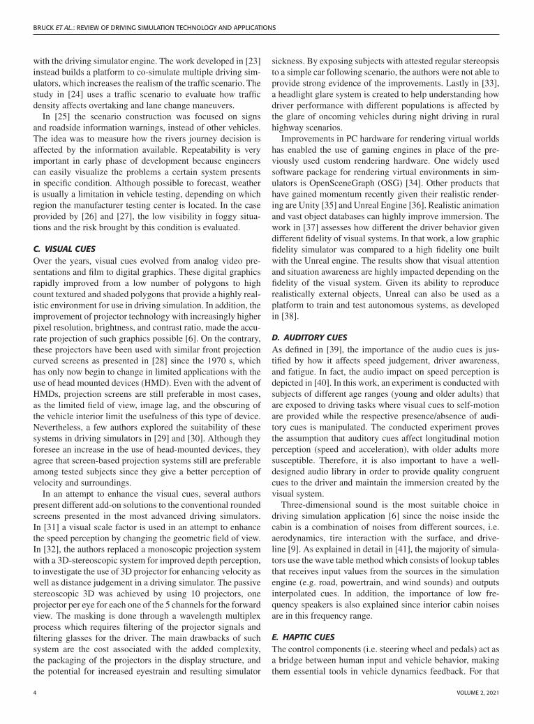
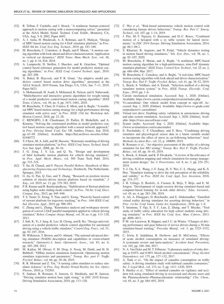
FIGURE 4. Diagram of an MPC motion cueing algorithm [42].
filter [53]. As shown in [54] and as depicted by the work-flow in Fig. 4, the inputs (i) given by the real driver arereceived by the vehicle dynamics model which passes forwardthe vehicles acceleration and angular velocities (a,v). Thisinformation must then be pre-processed to build a predictedsequence of reference variables. Often, the next step is toassess the vestibular model to build the perceived values ofacceleration and velocity. Other methods might simply use theangular velocity and specific force. As a final step, the systemdisplacement (d) is calculated in order to track the perceivedvalues before being handled to the motion control system.The importance of the reference over the MPC predictionhorizon is highlighted in [55] where the future behavior of thedriver is modelled as an optimal controller to have its behaviorpredicted and in [56] where the motion scale is treated asan optimization variable and a model of the kinematics ofa 7-DOF motion system is used for motion prediction. Inthis work it is shown that the separation of the penalty onthe motion gain from the overall target perception benefitsthe motion reproduction since excessive high-pass filtering
and tilt-coordination becomes not required when reproducinglong-period forces.
Although the process in the diagram is simple, the com-putational burden is complex given the presence of so manycomplex models. In [57], both the human vestibular systemand dynamic platform are modelled. For the vestibular system,linear transfer functions for the otoliths (translational motion)and for the semicircular canals (angular motion) are consid-ered. A multi-objective problem is solved using the sortinggenetic algorithm-II (NSGA-II) method, where the outputsare the gains for the translational and angular displacementsand velocities of the platform. The proposed nonlinear MPCin [58] uses a multi-sensory cueing algorithm (MSCA) thataccounts for the coordinates of the 9-DOF motion platformtogether with the coordinates for the active seat and activeseatbelt. In addition, a model of a seated driver is added to thevestibular model to predict the effects of the forces generatedby the seat and seatbelts. It is shown that this approach hasa great impact in compact simulator since the use of space isoptimized.
Although the MPC method has the potential to optimize theuse of space and the driver experience, its often-understatedlimitation resides in how far ahead it can foresee withoutcompromising the real time requirement. It is important tohighlight how imprecise prediction can undermine the fidelityof motion. Some works focused on different methods aimingto reduce the optimization time. In [59], a continuous-timerecurrent neural network (RNN) is used. In this work the au-thors model the dynamic platform kinematics and use a RNNto compute and apply the optimal trajectory of the platformonline.
It is possible to conclude that the MPC method allows betteruse of the available hardware and automated tuning of thecues when compared to the previous methods, although itsimplementation requires complex modelling of different sys-tems and massive computation power. Nevertheless, the MPCapproach is considered promising for enabling state-of-the-artsimulators to deliver best possible motion cueing.
G. KINEMATICSThe kinematics algorithm plays an important role connect-ing the motion cueing commands with the motion systemsstructure and hardware. The output of the motion cueingalgorithm is trajectory of the cabin in Cartesian space, andthis trajectory must be achieved by varying the length of theactuators. Therefore, actuators action is a function of desiredcabin motion. As explained in [60] and [61], the concept ofkinematics in driving simulation can be classified either asforward kinematics or inverse kinematics. The authors agreethat forward kinematics is the process of determining theposition of the motion platform once the actuators lengths areknown (or predefined). Inverse kinematics is the process ofacquiring the actuators length given the desired position ofthe motion platform. Likewise, in [62], inverse kinematics isdefined in a more generic way as the process of calculatingthe joint coordinates from the end-effector coordinates. In
6 VOLUME 2, 2021
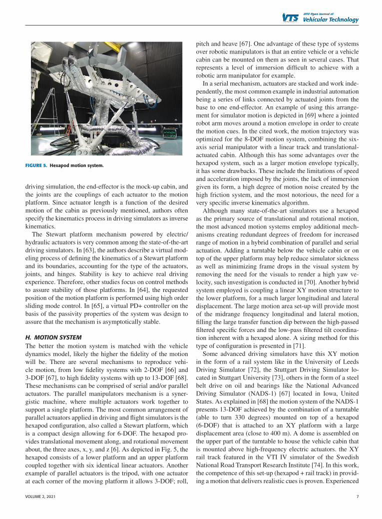
FIGURE 5. Hexapod motion system.
driving simulation, the end-effector is the mock-up cabin, andthe joints are the couplings of each actuator to the motionplatform. Since actuator length is a function of the desiredmotion of the cabin as previously mentioned, authors oftenspecify the kinematics process in driving simulators as inversekinematics.
The Stewart platform mechanism powered by electric/hydraulic actuators is very common among the state-of-the-artdriving simulators. In [63], the authors describe a virtual mod-eling process of defining the kinematics of a Stewart platformand its boundaries, accounting for the type of the actuators,joints, and hinges. Stability is key to achieve real drivingexperience. Therefore, other studies focus on control methodsto assure stability of those platforms. In [64], the requestedposition of the motion platform is performed using high ordersliding mode control. In [65], a virtual PD+ controller on thebasis of the passivity properties of the system was design toassure that the mechanism is asymptotically stable.
H. MOTION SYSTEMThe better the motion system is matched with the vehicledynamics model, likely the higher the fidelity of the motionwill be. There are several mechanisms to reproduce vehi-cle motion, from low fidelity systems with 2-DOF [66] and3-DOF [67], to high fidelity systems with up to 13-DOF [68].These mechanisms can be comprised of serial and/or parallelactuators. The parallel manipulators mechanism is a syner-gistic machine, where multiple actuators work together tosupport a single platform. The most common arrangement ofparallel actuators applied in driving and flight simulators is thehexapod configuration, also called a Stewart platform, whichis a compact design allowing for 6-DOF. The hexapod pro-vides translational movement along, and rotational movementabout, the three axes, x, y, and z [6]. As depicted in Fig. 5, thehexapod consists of a lower platform and an upper platformcoupled together with six identical linear actuators. Anotherexample of parallel actuators is the tripod, with one actuatorat each corner of the moving platform it allows 3-DOF; roll,
pitch and heave [67]. One advantage of these type of systemsover robotic manipulators is that an entire vehicle or a vehiclecabin can be mounted on them as seen in several cases. Thatrepresents a level of immersion difficult to achieve with arobotic arm manipulator for example.
In a serial mechanism, actuators are stacked and work inde-pendently, the most common example in industrial automationbeing a series of links connected by actuated joints from thebase to one end-effector. An example of using this arrange-ment for simulator motion is depicted in [69] where a jointedrobot arm moves around a motion envelope in order to createthe motion cues. In the cited work, the motion trajectory wasoptimized for the 8-DOF motion system, combining the six-axis serial manipulator with a linear track and translational-actuated cabin. Although this has some advantages over thehexapod system, such as a larger motion envelope typically,it has some drawbacks. These include the limitations of speedand acceleration imposed by the joints, the lack of immersiongiven its form, a high degree of motion noise created by thehigh friction system, and the most notorious, the need for avery specific inverse kinematics algorithm.
Although many state-of-the-art simulators use a hexapodas the primary source of translational and rotational motion,the most advanced motion systems employ additional mech-anisms creating redundant degrees of freedom for increasedrange of motion in a hybrid combination of parallel and serialactuation. Adding a turntable below the vehicle cabin or ontop of the upper platform may help reduce simulator sicknessas well as minimizing frame drops in the visual system byremoving the need for the visuals to render a high yaw ve-locity, such investigation is conducted in [70]. Another hybridsystem employed is coupling a linear XY motion structure tothe lower platform, for a much larger longitudinal and lateraldisplacement. The large motion area set-up will provide mostof the midrange frequency longitudinal and lateral motion,filling the large transfer function dip between the high-passedfiltered specific forces and the low-pass filtered tilt coordina-tion inherent with a hexapod alone. A sizing method for thistype of configuration is presented in [71].
Some advanced driving simulators have this XY motionin the form of a rail system like in the University of LeedsDriving Simulator [72], the Stuttgart Driving Simulator lo-cated in Stuttgart University [73], others in the form of a steelbelt drive on oil and bearings like the National AdvancedDriving Simulator (NADS-1) [67] located in Iowa, UnitedStates. As explained in [68] the motion system of the NADS-1presents 13-DOF achieved by the combination of a turntable(able to turn 330 degrees) mounted on top of a hexapod(6-DOF) that is attached to an XY platform with a largedisplacement area (close to 400 m). A dome is assembled onthe upper part of the turntable to house the vehicle cabin thatis mounted above high-frequency electric actuators. the XYrail track featured in the VTI IV simulator of the SwedishNational Road Transport Research Institute [74]. In this work,the competence of this set-up (hexapod + rail track) in provid-ing a motion that delivers realistic cues is proven. Experienced
VOLUME 2, 2021 7
BRUCK ET AL.: REVIEW OF DRIVING SIMULATION TECHNOLOGY AND APPLICATIONS
drivers were capable of noticing detailed handling differencescaused by variations of the vehicle parameters.
Although the system presented in [68] is considered to beone of the most capable of providing an accurate reproductionof real-world motion in a driving simulator, building systemssuch as this is not feasible for most testing centers, research in-stitutes, or even vehicle manufactures due to the very high costand physical space required. Using the concept of a hexapodand linear motion mechanisms, the Driver in Motion (DiM)9-DOF platform was designed. As detailed in [75], this type ofmotion system (DiM 150 and DiM 250) relies on the hexapodto provide rotational motion as well as small linear displace-ments. In addition, the hexapod is coupled to a planar tripodframe that slides on a flat surface through air pads, whichallows lateral, longitudinal and yaw motion. This redundantDOF design provides larger workspace use and system band-width when compared to the classical hexapods [54], but ata lower cost than larger linear motion systems. Other config-uration of the DiM simulator is presented in [59], DiM 700uses a central pulley (called discframe) driven by four cables.With this configuration, the DiM motion system achieves aneven larger motion envelope, which makes it a more suitablechoice for applications that require the reproduction of longersustained accelerations.
The DiM solution is objective of study of several pa-pers regarding MPC motion cueing algorithms such as [76],and figures as one product of higher motion fidelity. Whenbuilding a simulator, the definition of the motion system iskey, and should be done based on the intended application.The work in [77] develops an objective approach to be usedwhen selecting between a 2-DOF, 3-DOF, or 6-DOF motionsystems. The work also proposes a method to optimize themotion system geometry based on the future application ofthe driving simulator. Likewise, the work in [71] proposesan approach to lower the cost of the set-up by optimizingthe size of the motion system accounting for the availableworkspace and a high-fidelity motion response. Both workscan be used together as relevant guides for institutes lookingfor designing their own driving simulators. When designinga motion system, the actuators are equally as important asthe architecture. Most recent simulator hexapods use electricactuators in place of hydraulics due to their lower cost andmaintenance. They also allow for a higher motion bandwidth,but at a cost of higher friction and motion noise.
IV. STATE-OF-THE-ART DRIVING SIMULATORSThis session describes recent state-of-the-art driving simula-tors. The purpose is to give the reader examples of the appli-cation of previously mentioned systems. Older examples canbe found in literature [9]. Although the following examplesvary in number of degrees of freedom and fidelity, they allshow a highly immersive environment provided by real vehi-cle mock-ups and large field of view. It is important to notethe widespread use of desktop simulators in education andresearch centers, which are capable of meeting many researchneeds, but are not within the scope of the present survey.
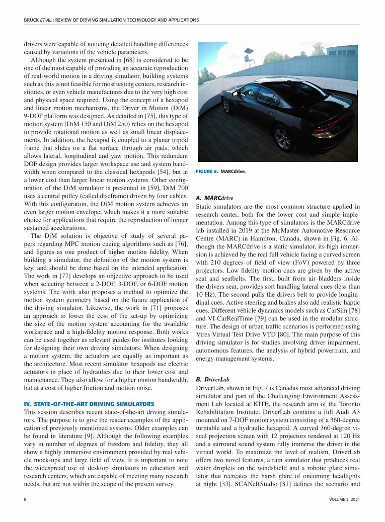
FIGURE 6. MARCdrive.
A. MARCdrive
Static simulators are the most common structure applied inresearch center, both for the lower cost and simple imple-mentation. Among this type of simulators is the MARCdrivelab installed in 2019 at the McMaster Automotive ResourceCentre (MARC) in Hamilton, Canada, shown in Fig. 6. Al-though the MARCdrive is a static simulator, its high immer-sion is achieved by the real full vehicle facing a curved screenwith 210 degrees of field of view (FoV) powered by threeprojectors. Low fidelity motion cues are given by the activeseat and seatbelts. The first, built from air bladders insidethe drivers seat, provides soft handling lateral cues (less than10 Hz). The second pulls the drivers belt to provide longitu-dinal cues. Active steering and brakes also add realistic hapticcues. Different vehicle dynamics models such as CarSim [78]and VI-CarRealTime [79] can be used in the modular struc-ture. The design of urban traffic scenarios is performed usingVires Virtual Test Drive VTD [80]. The main purpose of thisdriving simulator is for studies involving driver impairment,autonomous features, the analysis of hybrid powertrain, andenergy management systems.
B. DriverLab
DriverLab, shown in Fig. 7 is Canadas most advanced drivingsimulator and part of the Challenging Environment Assess-ment Lab located at KITE, the research arm of the TorontoRehabilitation Institute. DriverLab contains a full Audi A3mounted on 7-DOF motion system consisting of a 360-degreeturntable and a hydraulic hexapod. A curved 360-degree vi-sual projection screen with 12 projectors rendered at 120 Hzand a surround sound system fully immerse the driver in thevirtual world. To maximize the level of realism, DriverLaboffers two novel features, a rain simulator that produces realwater droplets on the windshield and a robotic glare simu-lator that recreates the harsh glare of oncoming headlightsat night [33]. SCANeRStudio [81] defines the scenario and
8 VOLUME 2, 2021
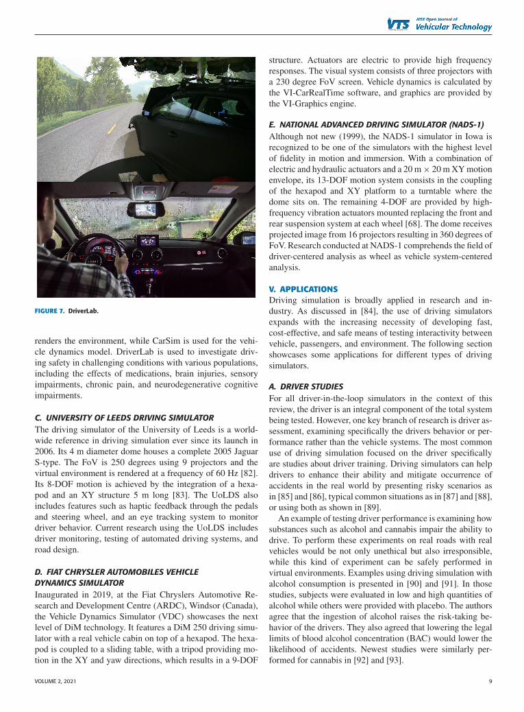
FIGURE 7. DriverLab.
renders the environment, while CarSim is used for the vehi-cle dynamics model. DriverLab is used to investigate driv-ing safety in challenging conditions with various populations,including the effects of medications, brain injuries, sensoryimpairments, chronic pain, and neurodegenerative cognitiveimpairments.
C. UNIVERSITY OF LEEDS DRIVING SIMULATORThe driving simulator of the University of Leeds is a world-wide reference in driving simulation ever since its launch in2006. Its 4 m diameter dome houses a complete 2005 JaguarS-type. The FoV is 250 degrees using 9 projectors and thevirtual environment is rendered at a frequency of 60 Hz [82].Its 8-DOF motion is achieved by the integration of a hexa-pod and an XY structure 5 m long [83]. The UoLDS alsoincludes features such as haptic feedback through the pedalsand steering wheel, and an eye tracking system to monitordriver behavior. Current research using the UoLDS includesdriver monitoring, testing of automated driving systems, androad design.
D. FIAT CHRYSLER AUTOMOBILES VEHICLEDYNAMICS SIMULATORInaugurated in 2019, at the Fiat Chryslers Automotive Re-search and Development Centre (ARDC), Windsor (Canada),the Vehicle Dynamics Simulator (VDC) showcases the nextlevel of DiM technology. It features a DiM 250 driving simu-lator with a real vehicle cabin on top of a hexapod. The hexa-pod is coupled to a sliding table, with a tripod providing mo-tion in the XY and yaw directions, which results in a 9-DOF
structure. Actuators are electric to provide high frequencyresponses. The visual system consists of three projectors witha 230 degree FoV screen. Vehicle dynamics is calculated bythe VI-CarRealTime software, and graphics are provided bythe VI-Graphics engine.
E. NATIONAL ADVANCED DRIVING SIMULATOR (NADS-1)Although not new (1999), the NADS-1 simulator in Iowa isrecognized to be one of the simulators with the highest levelof fidelity in motion and immersion. With a combination ofelectric and hydraulic actuators and a 20 m × 20 m XY motionenvelope, its 13-DOF motion system consists in the couplingof the hexapod and XY platform to a turntable where thedome sits on. The remaining 4-DOF are provided by high-frequency vibration actuators mounted replacing the front andrear suspension system at each wheel [68]. The dome receivesprojected image from 16 projectors resulting in 360 degrees ofFoV. Research conducted at NADS-1 comprehends the field ofdriver-centered analysis as wheel as vehicle system-centeredanalysis.
V. APPLICATIONSDriving simulation is broadly applied in research and in-dustry. As discussed in [84], the use of driving simulatorsexpands with the increasing necessity of developing fast,cost-effective, and safe means of testing interactivity betweenvehicle, passengers, and environment. The following sectionshowcases some applications for different types of drivingsimulators.
A. DRIVER STUDIESFor all driver-in-the-loop simulators in the context of thisreview, the driver is an integral component of the total systembeing tested. However, one key branch of research is driver as-sessment, examining specifically the drivers behavior or per-formance rather than the vehicle systems. The most commonuse of driving simulation focused on the driver specificallyare studies about driver training. Driving simulators can helpdrivers to enhance their ability and mitigate occurrence ofaccidents in the real world by presenting risky scenarios asin [85] and [86], typical common situations as in [87] and [88],or using both as shown in [89].
An example of testing driver performance is examining howsubstances such as alcohol and cannabis impair the ability todrive. To perform these experiments on real roads with realvehicles would be not only unethical but also irresponsible,while this kind of experiment can be safely performed invirtual environments. Examples using driving simulation withalcohol consumption is presented in [90] and [91]. In thosestudies, subjects were evaluated in low and high quantities ofalcohol while others were provided with placebo. The authorsagree that the ingestion of alcohol raises the risk-taking be-havior of the drivers. They also agreed that lowering the legallimits of blood alcohol concentration (BAC) would lower thelikelihood of accidents. Newest studies were similarly per-formed for cannabis in [92] and [93].
VOLUME 2, 2021 9
BRUCK ET AL.: REVIEW OF DRIVING SIMULATION TECHNOLOGY AND APPLICATIONS
Simulation can also be used to assess sources of distrac-tions. In [94] the influence surrounding vegetation has ondrivers attention is evaluated through the use of an eye tracker.The results show that the vegetation plays a minor influence inlongitudinal speed and lateral deviation although the roadsideclear zone width can impact driving safety. Another use ofan eye tracker system is presented in [95], where the systemmonitors drivers gaze to understand the effects of fatigue oneye tracking measures. It is shown that there is a significantchange in the pupil when the driver is alert compared to afatigued driver, demonstrating the effectiveness of the deviceon assessing fatigue. A similar device is introduced and testedin [96], using not only eye tracking but also heart rate and skinconductance measurements. Fatigue is also analyzed in [97],and how it leads to driver sleepiness during automated drives.In this paper a dedicated camera monitored head movement inaddition to drivers gaze and the results showed that commonfeatures used for detecting drowsiness during manual drivingmight not be sufficient for performing the same detection dur-ing automated driving. Other driver assessments that wouldrepresent potential harm if performed in real environmentbut are easily done using simulators include testing mobiledistractions [98], performance decay in older drivers [99], andthe effects of daylight on sleepiness [100].
Driving simulators can also be used to test human ma-chine interfaces (HMI). Some studies focus on how to de-sign an interface that will be better for the driver to inter-act with, where simulators can be of great help. That is thecase in [101], where the authors evaluate how drivers interactwith a secondary device. The participants interacted with atouchscreen, rotary-controller, steering-wheel-controls, and atouchpad. This type of analysis can rate the ease of use ofa device during the driving task and show what to employdepending on the purpose of the device. Again, performingthese tests in real life could compromise the safety of thepeople involved. In addition, the ease of integration and test-ing of such systems in a driving simulator can be beneficialcompared to implementing them in a real vehicle.
Most recently, the interaction between automated drivingsystems and drivers is being a subject of intense debate.In [102], the authors develop an approach to design and verifyan HMI system to facilitate the transition from automateddriving to manual driving. Other studies even propose inter-faces that aim to build trust between passengers and machinein fully automated scenarios, such as in [103]. In this work theauthors use VR system to provide the passenger a collectionof cues that shares information from the sensors and the routeplanning.
B. AUTONOMOUS SYSTEMS DEVELOPMENTDriving simulation can also be used to test autonomous andadvanced driver assistance systems (ADAS). A very commondriving assistant system is the adaptive cruise control (ACC).This feature allows the driver to specify its maximum speedand minimum distance to the preceding vehicle. Examples ofthis work can be seen in [104] where driving simulation is
used to explore the use of an ACC system in traffic situations,and in [105] where system failure is explored in differenttraffic scenarios.
One of the most important scenarios involving human in-teraction with ADAS is explored in [106], where the take-over maneuver is evaluated in different conditions. The vol-unteers had to face a forward collision situation with threedifferent systems: autonomous vehicle with and without colli-sion avoidance assistant, and manual drive mode. The resultsshowed a lack of reaction by subjects when driving in theautonomous modes. In fact, the take-over maneuver is objectof study of several papers regarding ADAS. In [107] take-overrequest is studied and an investigation of the orientation of thetactical alert given to the driver (whether towards to the hazardor away from it) is conducted. The transition is assessed in alane change maneuver where the current lane presents a haz-ard four seconds ahead. In [108], tactile, visual, and auditoryrequests are given to the driver in order to understand thedifferences those modalities have in gaining drivers attention.The work in [109] highlights the importance of instruction anddriver training on using ADAS.
Other works assessing take-over maneuvers can be foundin [110] where different drivers are evaluated during a failureof the autonomous system, and in [111] where truck driversface time critical take-over situations while performing a non-driving tasks. In [112], the authors evaluate how scheduledmanual driving affects drowsiness and contribute to bettertake-over maneuvers when needed. In [113], an autonomousemergency braking system (AEB) that adapts to road frictionis evaluated in comparison to a non-adaptable system. Thisscenario illustrates the highest level of assistance a drivingsimulator can provide during vehicle design because it alliesthe validation of a new safety feature in a driving condi-tion very difficult to reproduce consistently (i.e. low-frictionsnowy road). It also highlights the importance of the abilityto adapt to a changing situation or condition. Another exam-ple of AEB assessment is presented in [114], where severalvehicle-bicycle imminent collision events are proposed withthe objective of redesigning validation tests in order to covera larger number of scenarios. A very well-known system isthe lane keeping assistant. As described in [115], the lanekeeping system helps the driver to keep the vehicle on alane by applying torque (also called haptic feedback) to thesteering wheel. In this work, the impact this system has ondrivers fatigue during monotonous driving is investigated bymonitoring the standard deviation of lateral position. The ben-efit of haptic feedback is also evaluated in [116], where theauthors found that whole-body feedback during curves can beeffective in avoiding hazardous situations when take-over isneeded. Furthermore, in [117], a real-time adaptable hapticfeedback is proposed based on the level of distraction of thedriver.
Finally, driving simulation can be used to test the inter-action between fully autonomous vehicles and passengers.In [118], the authors investigate the preference of passengersregarding the level of information the autonomous system
10 VOLUME 2, 2021
exchanges, such as sensor information, directions, and status.This study points out that different users will require differentlevels of information, which should be accounted for when de-signing autonomous systems. Smoothness of the autonomousdriving is assessed in [72], where a non-linear model predic-tive control (NMPC) is developed to govern the vehicle trajec-tory, accounting for safety and comfort, intended to developa system with a human-like behavior. Another assessment ofan autonomous driving system from the perspective of thepassengers is depicted in [119]. Here, passengers eye move-ment is tracked using eye tracking systems to rate the trust inthe system. In this work, the results show that driving stylesappeared to affect the trust. This shows a relevant paradigm inthe use of driving simulators for autonomous systems testing.Not only should safety and efficiency be pursued, but alsointeraction and compliance with passengers expectations ofmotion, to achieve mainstream acceptability and a comfort-able driving experience.
C. CHASSIS SYSTEMS DEVELOPMENTIn industry, one of the mainstream uses of driving simulatorsis for subjective dynamic evaluation and pre-design of chassiscomponents. Although this is one of the larger use cases,due to the confidential nature of industry work, publicationsare not common. The work performed in [74] proves thatexperienced drivers are able to identify handling differencesgiven parameter modifications using a driving simulator. Theauthors used different vehicle parameters such as roll stiffnessand tire compliance to reproduced well-known maneuvers,e.g. single lane change. The driver subjective feeling wascompared, as well as a comparison between the actual mea-surements and virtual values of yaw rate, roll, and steeringtorque. The results motivate works tuning lateral dynamicsthrough suspension, steering, and active control systems. Asimilar test is conducted in [120], where acceleration of thedrivers head was measured during a braking maneuver in areal vehicle and in a 6-DOF simulator. The study was toinvestigate if the whiplash motion of the neck could be re-produced in the simulator, validating its use for longitudinaldynamics assessments. In [121], different configurations ofthe steering system are tested by several subjects in threedifferent scenarios, to evaluate how the environment and thesystem influence the drivers perception of controllability, easeof use and fun while driving. The work developed in [122]goes even deeper into an active steering system and proposeda new model that incorporates drivers gaze, justified by thefact that the steering behavior of drivers change with sightlinedistances. The results show that this concept can be furtherused in autonomous systems, since it was shown to achievemore precision than current proportional-integral-derivative(PID) controllers.
As mentioned before, suspension systems are also an objectof study in driving simulation, due to the ease of changingcomponents, configurations, geometry, and dynamics withoutprototyping parts. For active systems, different tunings can beassessed without the need for software compilation. Active
control systems such as electronic stability control (ESC) canalso be tuned through driving simulation. The work detailedin [123] uses the driving simulator to prove the loss of controlreduction provided by the ESC system. In that work, 120 sub-jects drove into typical crash situations with and without theassistance system. The results show the benefit of having ESCin all scenarios. Another work featuring an ESC system isdepicted in [124], where vehicle behavior during anti-rolloverinterventions is investigated. This kind of test is importantas it shows how safety systems behave in standard validationmaneuvers compared to how well they perform in real worldexperiments.
More recent work described in [83] assesses the validityof a driving simulator in mimicking the dynamics of a low-friction test track, showing that although driving simulationcan be used for dynamic assessment, there are still limitationsin reproducing certain maneuvers and environments.
D. POWERTRAIN SYSTEMS DEVELOPMENTCertain aspects of powertrain design can also be studied indriving simulation environment. Given the increase of pol-lution and imminent shortage of fuel resources, the electri-fication of powertrain systems is gaining momentum, withresearch in this field indicating that this technology will bekey to solving the energy issue [125]. Several energy manage-ment strategies (EMS) have been developed in the past fewyears [126] for many different powertrain configurations [127]in consideration of the electrification trend, with the ob-jective of reducing energy consumption and raising vehicleefficiency.
In addition, the importance of the journey mapping anddriving conditions (e.g. pavement, weather, and traffic) ishighlighted by several researchers [83] and [128]. Once more,driving simulation can be a powerful tool, reducing designtiming and cost, providing controlled environments, and al-lowing integration of technologies beforehand. In powertraindesign, the HMI analysis is also important. An investigationon how augmented reality (AR) displays can guide the driverduring the driving task is proposed in [129], where a hy-brid electric vehicle (HEV) is emulated using a co-simulationbetween a hardware in the loop (HIL) test rig and a driv-ing simulator. This study showed that fuel efficiency can beincreased using simple display systems that guide the driverduring the journey. The same concept is explored in [130]and [131], where the ability to foresee events using a V2X(vehicle to road/vehicle/database communication) is used inorder to display instructions to the driver.
Using the same concept of driver guidance, several eco-driving studies were performed in [132] and [133] to evaluatefuel consumption improvement by instructing drivers on eco-friendly driving behavior. The work in [134] investigates therole gas pedal feedback can play in making drivers achieve ahigher fuel efficiency. In this work two different pedal systemswere tested by twenty drivers. The results show that the mostfuel-efficient behavior is achieved when drivers are provided
VOLUME 2, 2021 11
BRUCK ET AL.: REVIEW OF DRIVING SIMULATION TECHNOLOGY AND APPLICATIONS
guiding force feedback (such as a step change in the pedalforce) compared to a system that provided increased firmness.
In another study examining fuel consumption, [135] inte-grates a static simulator with a dynamometer. This integrationmakes it possible to evaluate the performance of electric vehi-cle (EV) systems in tests performed by real human in severaldriving conditions. In [136], ten different drivers were placedin a car following scenario that replicates a realistic drivermodel for fuel economy assessment of a HEV. The differentdriver behaviors were analyzed and categorized. This data isused to develop a car following driver model for evaluatingfuel consumption, and to create a reference virtual driver thatcan provide real time feedback to human drivers.
Subjective longitudinal acceleration can also be validatedusing driving simulation. The authors in [137] used a 6-DOFdriving simulator to present different engine configurations todrivers in a tip-in maneuver defined by a sudden step on theaccelerator pedal from a constant engine speed (1500 rpm insecond gear) without gearshift. The results showed that drivershave the sensibility to perceive changes in the accelerationprofile for different engine configurations. That indicates thatdriving simulators can be used for subjective drivability as-sessment of powertrains prior to prototyping. In addition, theauthors in [138] have shown that it is possible to categorizeacceleration levels. That is an important insight to HEV de-velopers since drivability and drivers perception has very tightrequirements.
E. ROAD DESIGNIn addition to the aforementioned vehicle design, road designcan also be studied and improved through driving simulation.In [139], driving performance is evaluated for different config-urations of road signs. A similar work is presented in [140],where audio warnings through differing pavement surfaces(rumble strips) in addition to visual warnings were examined,something that would be costly to create in a physical envi-ronment.
VI. CONCLUSIONThis review has explained the mechanisms of drivingsimulation technology by describing each system in thearchitecture. The human perceptual system was also brieflyexplained since the purpose of a driving simulator is to evokea desired response from that system while imitating thedriving experience.
Current state-of-the-art simulators are also presented, to-gether with their most important characteristics and typicaluses. These state-of-the-art systems aim for the highest levelof fidelity by providing highly immersive set-ups with fullvehicle mock-ups, a large field of view, and accurate vehicledynamics models. The ability to create and control drivingconditions and scenarios such as weather and traffic are alsokey. When using motion, these simulators also include well-developed motion cueing algorithms that account not only forthe limitations of the human perceptual system but also for theboundaries of the motion system. Static simulators can often
be used in studies where the focus is not primarily closedloop control of the vehicle by a human driver, while motionsimulators offer an increased scope of use, including analysisof chassis control and autonomous features.
The final section has shown several examples of drivingsimulation use. It is important to highlight that the three of themost important benefits of driving simulation are the safetyfor subject drivers and other road users, the reduction of timein design phase, and the ability to reproduce a variety ofcontrolled scenarios and conditions. In addition, it is possibleto foresee positive prospects for expanded driving simulationuse. The increasing momentum of autonomous and activecontrol systems means that more virtual validation of thesesystems will be required in the future. Further, despite someclaims that autonomous driving would mean less driver-in-the-loop simulation (due to less human driving), the need fora platform to test system acceptability and to train users willrequire increased use of simulation, similar to patterns thatcan be observed in the history of aerospace development. Theneed for environments that show no harm for the occupantsand that can produce precise and reproducible emergency situ-ations will also increase. The same increased use of simulationalso holds for the electrification process.
Although some studies were already performed assessingpowertrain systems, these analyses will become more com-mon and precise as the need to virtually validate those systemsincreases. Moreover, driving simulation allows the valida-tion of the interaction between different systems, both at thecomponent and system level. It enables engineers to test theintegration between autonomous systems with active safetysystems for example, as well as analyzing it from the driversperspective. This integrated interactive approach is key todevelop systems that work as one.
Finally, the next generation of driving simulators will showhigh connectivity with other testing apparatuses, such ashuman condition tracking devices, mobile phones, and dy-namometers. Although few works were found in this area,the necessity of integrating testing systems is clear given thenecessity of integrating vehicle systems. The use of drivingsimulation is destined to increase, saving time as well asraising the safety of tests.
REFERENCES[1] J. Slob, “State-of-the-art driving simulators, a literature survey,” Eind-
hoven Univ. Technol., Eindhoven, Netherlands, Tech. Rep. DCT2008.107, Aug. 2008.
[2] H. H. Valverde, “A review of flight simulator transfer of trainingstudies,” Hum. Factors, vol. 15, no. 6, pp. 510–522, 1973.
[3] G. Miles and D. Vincent, “The institutes tests for motor drivers,” TheHum. Factor, vol. 8, no. 7, pp. 245–257, 1934.
[4] W. W. Wierwille and P. P. Fung, “Comparison of computer-generatedand simulated motion picture displays in a driving simulation,” Hum.Factors, vol. 17, no. 6, pp. 577–590, 1975.
[5] J. Gruening, J. Bernard, C. Clover, and K. Hoffmeister, “Driving sim-ulation,” SAE Trans., vol. 107, pp. 376–385, 1998.
[6] E. Blana, A survey of driving research simulators around the world.Institute for Transport Studies, University of Leeds, Leeds, U.K.,Dec. 1996. [Online]. Available: http://eprints.whiterose.ac.uk/2110/
12 VOLUME 2, 2021
[7] D. L. Fisher, M. Rizzo, J. Caird, and J. D. Lee, Handbook of DrivingSimulation for Engineering, Medicine, and Psychology. Boca Raton,FL: CRC Press, 2011.
[8] A. H. J. Jamson, “Motion cueing in driving simulators for researchapplications,” Ph.D. dissertation, Univ. Leeds, Leeds, U.K., Nov. 2010.[Online]. Available: http://etheses.whiterose.ac.uk/1915/
[9] N. Mohajer, H. Abdi, K. Nelson, and S. Nahavandi, “Vehicle motionsimulators, a key step towards road vehicle dynamics improvement,”Veh. Syst. Dyn., vol. 53, no. 8, pp. 1204–1226, 2015.
[10] P. Zaal, F. Nieuwenhuizen, M. Mulder, and M. van Paassen, “Percep-tion of visual and motion cues during control of self-motion in opticflow environments,” presented at the AIAA Model. Simul. Technol.Conf. Exhib., Keystone, CO, USA, Aug. 21–24, 2006, Paper 6627.
[11] R. Wilkie and J. Wann, “Controlling steering and judging heading:Retinal flow, visual direction, and extraretinal information,” J. Exp.Psychol.: Hum. Perception Perform., vol. 29, no. 2, pp. 363–378, 2003.
[12] B. Keshavarz, J. L. Campos, P. R. DeLucia, and D. Oberfeld, “Esti-mating the relative weights of visual and auditory tau versus heuristic-based cues for time-to-contact judgments in realistic, familiar scenesby older and younger adults,” Attention, Perception, Psychophys.,vol. 79, no. 3, pp. 929–944, 2017.
[13] B. Keshavarz, L. J. Hettinger, D. Vena, and J. L. Campos, “Combinedeffects of auditory and visual cues on the perception of vection,” Exp.Brain Res., vol. 232, no. 3, pp. 827–836, 2014.
[14] J. R. Lackner and P. DiZio, “Vestibular, proprioceptive, and hapticcontributions to spatial orientation,” Annu. Rev. Psychol., vol. 56,pp. 115–147, 2005.
[15] E. P. Widmaier, H. Raff, K. T. Strang, and A. J. Vander, Vander’s Hum.Physiology: The mechanisms of body function. Boston, MA: McGraw-Hill Higher Education, 2008.
[16] G. Markkula, R. Romano, R. Waldram, O. Giles, C. Mole, andR. Wilkie, “Modelling visual-vestibular integration and behaviouraladaptation in the driving simulator,” Transp. Res. Part F: Traffic Psy-chol. Behav., vol. 66, pp. 310–323, 2019.
[17] Smart: Servier medical art - ears. Accessed: Sep. 7, 2020. [On-line]. Available: https://smart.servier.com/category/anatomy-and-the-human-body/auditory-system/ears/
[18] O. Balci, “Verification, validation, and certification of modeling andsimulation applications,” in Proc. Winter Simul. Conf., 2003, vol. 1,pp. 150–158.
[19] R. N. Jazar, Vehicle Dynamics: Theory and Application. Cham,Switzerland: Springer, 2017.
[20] D. Schramm, M. Hiller, and R. Bardini, Vehicle Dynamics: Modelingand Simulation. Berlin, Germany: Springer, 2014.
[21] T. D. Gillespie, Fundamentals of Vehicle Dynamics. Warrendale, PA,USA: Society of Automotive Engineers, 1992.
[22] M. Matowicki, O. Pribyl, and P. Bouchner, “Pragmatic overview ofsurrounding traffic implementation into driving simulator,” in Proc.ELEKTRO, 2016, pp. 423–428.
[23] J. Sun, Z. Ma, T. Li, and D. Niu, “Development and application ofan integrated traffic simulation and multi-driving simulators,” Simul.Modelling Pract. Theory, vol. 59, pp. 1–17, 2015.
[24] L. Yang, X. Li, W. Guan, H. M. Zhang, and L. Fan, “Effect of trafficdensity on drivers lane change and overtaking maneuvers in free-way situation driving simulator based study,” Traffic Inj. Prevention,vol. 19, no. 6, pp. 594–600, 2018.
[25] S. Sharples, S. Shalloe, G. Burnett, and D. Crundall, “Journey decisionmaking: The influence on drivers of dynamic information presentedon variable message signs,” Cognit., Technol. Work, vol. 18, no. 2,pp. 303–317, 2016.
[26] D. Xiao, Y. Fang, Y. Zhang, and Z. Guo, “Analysis of driving behaviorat the bridge-tunnel transition section in reduced visibility situations,”in Proc. 4th Int. Conf. Transp. Inf. Safety, 2017, pp. 581–588.
[27] X. Chang, H. Li, L. Qin, J. Rong, Y. Lu, and X. Chen, “Evaluationof cooperative systems on driver behavior in heavy fog conditionbased on a driving simulator,” Accident Anal. Prevention, vol. 128,pp. 197–205, 2019.
[28] R. Kemmerer Jr, S. Hulbert, and R. Donohue, “UCLA driving sim-ulation laboratory: With a 360 degree scene around a full size car,”in Proc. Simulators Simul. II: Des., Appl. Technol., Int. Soc. OpticsPhoton., 1975, vol. 59, pp. 158–170.
[29] B. Blissing and F. Bruzelius, “Exploring the suitability of virtualreality for driving simulation,” in Proc. Driving Simul. Conf., 2018,pp. 163–166.
[30] C. Zller, A. Mller, L. Eggert, H. Winner, and B. Abendroth, “Ap-plicability of head-mounted displays in driving simulation,” in Proc.Driving Simul. Conf. Eur. VR, A. Kemeny, F. Colombet, F. Merienne,and S. Espi, Eds., Strasbourg, France: Driving Simulation Association,2019, pp. 9–15.
[31] F. Colombet, D. Paillot, F. Mérienne, and A. Kemeny, “Visual scalefactor for speed perception,” J. Comput. Inf. Sci. Eng., vol. 11, no. 4,2011.
[32] H. Schmieder, K. Nagel, and H.-P. Schoener, “Enhancing a drivingsimulator with a 3d-stereo projection system,” in DSC 2017 Eur.Driving Simulation Association, 2017, pp. 103–110.
[33] B. Haycock, J. Campos, N. Koenraad, M. Potter, and S. Advani,“Creating headlight glare in a driving simulator,” Transp. Res. PartF: Traffic Psychol. Behav., vol. 61, pp. 93–106, 2019.
[34] The openscene graph project. Accessed: Sep. 1, 2020. [Online]. Avail-able: http://www.openscenegraph.org/
[35] Unity for all. Accessed: Sep. 1, 2020. [Online]. Available: https://unity.com/
[36] Unreal engine. make something unreal. Accessed: Sep. 1, 2020. [On-line]. Available: https://www.unrealengine.com/en-US/
[37] C. Merenda, C. Suga, J. Gabbard, and T. Misu, “Effects of vehicle sim-ulation visual fidelity on assessing driver performance and behavior,”in Proc. IEEE Intell. Veh. Symp. (IV), 2019, pp. 1679–1686.
[38] J. Leudet, F. Christophe, T. Mikkonen, and T. Männistö, “Ailivesim:An extensible virtual environment for training autonomous vehicles,”in Proc. IEEE 43rd Annu. Comput. Softw. Appl. Conf. (COMPSAC),vol. 1, 2019, pp. 479–488.
[39] D. A. Heitbrink and S. Cable, “Design of a driving simulationsound engine,” presented at the Driving Simul. Conf., North Amer.2007 (DSC-NA 2007), Iowa City, IA, USA, Sep. 12–14, 2007, Pa-per N2007-028.
[40] R. Ramkhalawansingh, B. Keshavarz, B. Haycock, S. Shahab, and J.L. Campos, “Age differences in visual-auditory self-motion perceptionduring a simulated driving task,” Front. Psychol., vol. 7, pp. 595.1–595.12, 2016. [Online]. Available: https://app.dimensions.ai/details/publication/pub.1014944210
[41] R. Suikat, “The new dynamic driving simulator at dlr,” in Proc. Driv-ing Simulator Conf., no. 8, 2005, pp. 374–381.
[42] M. Bruschetta, F. Maran, and A. Beghi, “A fast implementationof mpc-based motion cueing algorithms for mid-size road vehiclemotion simulators,” Veh. Syst. Dyn., vol. 55, no. 6, pp. 802–826,2017.
[43] L. Nehaoua, H. Mohellebi, A. Amouri, H. Arioui, S. Espie, andA. Kheddar, “Design and control of a small-clearance driving sim-ulator,” IEEE Trans. Veh. Technol., vol. 57, no. 2, pp. 736–746,Mar. 2008.
[44] Z. Fang, M. Tsushima, E. Kitahara, N. Machida, D. Wautier, andA. Kemeny, “Motion cueing algorithm for high performance driv-ing simulator using yaw table,” IFAC-PapersOnLine, vol. 50, no. 1,pp. 15 965–15 970, 2017.
[45] L. Reid and M. Nahon, “Flight simulation motion-base drive al-gorithms: Part 1. Developing and testing equations,” UTIAS Rep.,no. 296, 1985.
[46] Z. Fang and A. Kemeny, “Motion cueing algorithms for a real-timeautomobile driving simulator,” in Proc. Driving Simul. Conf., 2012,pp. 159–174.
[47] H. Asadi, C. P. Lim, S. Mohamed, D. Nahavandi, and S. Nahavandi,“Increasing motion fidelity in driving simulators using a fuzzy-basedwashout filter,” IEEE Trans. Intell. Veh., vol. 4, no. 2, pp. 298–308,Jun. 2019.
[48] T. Miunske, C. Holzapfel, E. Baumgartner, and H.-C. Reuss, “A newapproach for an adaptive linear quadratic regulated motion cueingalgorithm for an 8 DoF full motion driving simulator,” in Proc. Int.Conf. Robot. Autom., 2019, pp. 497–503.
[49] S.-H. Chen and L.-C. Fu, “An optimal washout filter design for amotion platform with senseless and angular scaling maneuvers,” inProc. Amer. Control Conf., 2010, pp. 4295–4300.
[50] H. Asadi, S. Mohamed, C. P. Lim, and S. Nahavandi, “Robust opti-mal motion cueing algorithm based on the linear quadratic regulatormethod and a genetic algorithm,” IEEE Trans. Syst., Man, Cybern.:Syst., vol. 47, no. 2, pp. 238–254, Feb. 2017.
[51] R. Sivan, J. Ish-Shalom, and J.-K. Huang, “An optimal control ap-proach to the design of moving flight simulators,” IEEE Trans. Syst.,Man, Cybern., vol. 12, no. 6, pp. 818–827, Nov. 1982.
VOLUME 2, 2021 13
BRUCK ET AL.: REVIEW OF DRIVING SIMULATION TECHNOLOGY AND APPLICATIONS
[52] R. Telban, F. Cardullo, and J. Houck, “A nonlinear, human-centeredapproach to motion cueing with a neurocomputing solver,” presentedat the AIAA Model. Simul. Technol. Conf. Exhib., Monterey, CA,USA, Aug. 5–8, 2002, Paper 4692.
[53] A. I. Aulia, H. Hindersah, A. S. Rohman, and E. Hidayat, “Designof MPC-based motion cueing for 4 DoF simulator platform,” in Proc.IEEE 9th Int. Conf. Syst. Eng. Technol., 2019, pp. 183–188.
[54] M. Bruschetta, C. Cenedese, A. Beghi, and F. Maran, “A motion cue-ing algorithm with look-ahead and driver characterization: Applicationto vertical car dynamics,” IEEE Trans. Hum.-Mach. Syst., vol. 48,no. 1, pp. 6–16, Feb. 2018.
[55] A. Lamprecht, D. Steffen, J. Haecker, and K. Graichen, “Optimalcontrol based reference generation for model predictive motion cue-ing algorithms,” in Proc. IEEE Conf. Control Technol. Appl., 2019,pp. 203–208.
[56] A. Bukal, B. Haycock, and P. R. Grant, “An adaptive model pre-dictive control based motion drive algorithm,” presented at theAIAA Scitech. 2019 Forum, San Diego, CA, USA, Jan. 7–11, 2019,Paper 0423.
[57] A. Mohammadi, H. Asadi, S. Mohamed, K. Nelson, and S. Nahavandi,“Multiobjective and interactive genetic algorithms for weight tuningof a model predictive control-based motion cueing algorithm,” IEEETrans. Cybern., vol. 49, no. 9, pp. 3471–3481, 2018.
[58] M. Bruschetta, Y. Chen, D. Cunico, E. Mion, and A. Beghi, “A nonlin-ear MPC based motion cueing strategy for a high performance drivingsimulator with active seat,” in Proc. IEEE 15th Int. Workshop Adv.Motion Control, 2018, pp. 23–28.
[59] C. RENGIFO, J.-R. Chardonnet, D. Paillot, H. Mohellebi, and A.Kemeny, “Solving the constrained problem in model predictive con-trol based motion cueing algorithm with a neural network approach,”in Proc. Driving Simul. Conf. Eur. VR, Antibes, France, Sep. 2018,pp. 63–69. [Online]. Available: https://hal.archives-ouvertes.fr/hal-01940772
[60] Y. Chiew, M. A. Jalil, and M. Hussein, “Kinematic modeling of drivingsimulator motion platform,” in Proc. IEEE Conf. Innov. Technol. Intell.Syst. Ind. Appl., 2008, pp. 30–34.
[61] J. G. Zeng, J. Y. Liu, and Q. Yu, “Design and developmentof 6dof hydraulic motion platform for vehicle driving simulator,”in Proc. Appl. Mech. Mater., vol. 505 Trans Tech Publ, 2014,pp. 315–318.
[62] Y. Jin, H. Chanal, and F. Paccot, Parallel Robots. Handbook of Man-ufacturing Engineering and Technology. Dordrecht, The Netherlands:Springer, 2015.
[63] G. Jia, G. Pan, Q. Gao, and Y. Zhang, “Research on position inversesolution of electric-driven stewart platform based on simulink,” J.Eng., vol. 2019, no. 13, pp. 379–383, 2019.
[64] P. R. Kumar and B. Bandyopadhyay, “Stabilization of Stewart platformusing higher order sliding mode control,” in Proc. 7th Int. Conf. Elect.Comput. Eng., 2012, pp. 945–948.
[65] T. S. Tamir, G. Xiong, Y. Tian, and G. Xiong, “Passivity based controlof stewart platform for trajectory tracking,” in Proc. 14th IEEE Conf.Ind. Electron. Appl., 2019, pp. 988–993.
[66] C. Zhang and L. Zhang, “Kinematics analysis and workspace investi-gation of a novel 2-DoF parallel manipulator applied in vehicle drivingsimulator,” Robot. Comput.-Integr. Manuf., vol. 29, no. 4, pp. 113–120,2013.
[67] J. Suh, K. Yi, J. Jung, K. Lee, H. Chong, and B. Ko, “Design and eval-uation of a model predictive vehicle control algorithm for automateddriving using a vehicle traffic simulator,” Control Eng. Pract., vol. 51,pp. 92–107, 2016.
[68] M. Wilkinson, T. Brown, and O. Ahmad, “The national advanced driv-ing simulator (NADS) description and capabilities in vision-relatedresearch,” Optometry-J. Amer. Optometric Assoc., vol. 83, no. 6,pp. 285–288, 2012.
[69] M. Katliar, M. Olivari, F. M. Drop, S. Nooij, M. Diehl, and H. H.Bülthoff, “Offline motion simulation framework: Optimizing motionsimulator trajectories and parameters,” Transp. Res. part F: TrafficPsychol. Behav., vol. 66, pp. 29–46, 2019.
[70] R. R. Mourant and Z. Yin, “A turning cabin simulator to reduce sim-ulator sickness,” in Proc. Eng. Reality Virtual Reality, Int. Soc. OpticsPhoton., 2010, p. 752503.
[71] E. Sadraei, R. Romano, S. Jamson, G. Markkula, and H. Jamson,“Driving simulator motion base right sizing,” in DSC 2018 Europe.Driving Simulation Association, 2018, pp. 113–120.
[72] C. Wei et al., “Risk-based autonomous vehicle motion control withconsidering human drivers behaviour,” Transp. Res. Part C: Emerg.Technol., vol. 107, pp. 1–14, 2019.
[73] J. Pitz, M.-T. Nguyen, G. Baumann, and H.-C. Reuss, “Combinedmotion of a hexapod with a xy table system for lateral move-ments,” in DSC 2014 Europe. Driving Simulation Association, 2014,pp. 06.1–06.2.
[74] S. Kharrazi, B. Augusto, and N. Fröjd, “Vehicle dynamics testingin motion based driving simulators,” Veh. Syst. Dyn., vol. 58, no. 1,pp. 92–107, 2020.
[75] M. Bruschetta, F. Maran, and A. Beghi, “A nonlinear, MPC-basedmotion cueing algorithm for a high-performance, nine-DoF dynamicsimulator platform,” IEEE Trans. Control Syst. Technol., vol. 25, no. 2,pp. 686–694, Mar. 2017.
[76] M. Bruschetta, C. Cenedese, and A. Beghi, “A real-time, MPC-basedmotion cueing algorithm with look-ahead and driver characterization,”Transp. Res. Part F: Traffic Psychol. Behav., vol. 61, pp. 38–52, 2019.
[77] L. Bruck, S. Veldhuis, and A. Emadi, “Selection method of a drivingsimulator motion system,” in Proc. IEEE Transp. Electrific. Conf.Expo., 2019, pp. 1–6.
[78] Carsim mechanical simulation. Accessed: Sep. 1, 2020. [Online].Available: https://www.carsim.com/products/carsim/index.php
[79] Vi-carrealtime: One vehicle model from concept to sign-off. Ac-cessed: Sep. 1, 2020. [Online]. Available: https://www.vi-grade.com/en/products/vi-carrealtime/
[80] Virtual test drive: Enabling safety validation in autonomous drivingand adas system simulation. Accessed: Sep. 1, 2020. [Online]. Avail-able: https://vires.mscsoftware.com/
[81] Scaner studio. Accessed: Sep. 1, 2020. [Online]. Available: https://www.avsimulation.com/scanerstudio/
[82] E. Paschalidis, C. F. Choudhury, and S. Hess, “Combining drivingsimulator and physiological sensor data in a latent variable modelto incorporate the effect of stress in car-following behaviour,” Anal.Methods Accident Res., vol. 22, p. 100089, 2019.
[83] R. Romano et al., “An objective assessment of the utility of a drivingsimulator for low MU testing,” Transp. Res. Part F: Traffic Psychol.Behav., vol. 65, pp. 34–45, 2019.
[84] L. Bruck, A. Emadi, and K. P. Divakarla, “A review of the relevance ofdriving condition mapping and vehicle simulation for energy manage-ment system design,” Int. J. Powertrains, vol. 8, no. 3, pp. 224–251,2019.
[85] Y.-J. Ou, X.-L. Wang, J.-F. Jiang, H.-Y. Wei, C.-L. Huang, and K.-S.Hsu, “Simulator training to drive the risk perception of the reliabilityand validity,” in Proc. IEEE Int. Conf. Appl. Syst. Invention, 2018,pp. 374–377.
[86] J. H. Urlings, E. Roelofs, A. Cuenen, K. Brijs, T. Brijs, and E. M.Jongen, “Development of single-session driving simulator-based andcomputer-based training for at-risk older drivers,” Educ. Gerontol.,vol. 45, no. 4, pp. 283–296, 2019.
[87] A. Ali, A. Elnaggarz, D. Reichardtz, and S. Abdennadher, “Gamifiedvirtual reality driving simulator for asserting driving behaviors,” inProc. 1st Int. Conf. Game, Game Art, Gamification., 2016, pp. 1–6.
[88] T. Imamura, T. Ogi, E. T. C. Lun, Z. Zhang, and T. Miyake, “Trialstudy of traffic safety education for high school students using driv-ing simulator,” in Proc. IEEE Int. Conf. Syst., Man, Cybern., 2013,pp. 4606–4611.
[89] P. M. van Leeuwen, R. Happee, and J. C. de Winter, “Changes of driv-ing performance and gaze behavior of novice drivers during a 30-minsimulator-based training,” Procedia Manuf., vol. 3, pp. 3325–3332,2015.
[90] C. Irwin, E. Iudakhina, B. Desbrow, and D. McCartney, “Effectsof acute alcohol consumption on measures of simulated driving:A systematic review and meta-analysis,” Accident Anal. Prevention,vol. 102, pp. 248–266, 2017.
[91] N. A. Van Dyke and M. T. Fillmore, “Laboratory analysis of risky driv-ing at 0.05% and 0.08% blood alcohol concentration,” Drug AlcoholDependence, vol. 175, pp. 127–132, 2017.
[92] A. Tank et al., “On the impact of cannabis consumption on trafficsafety: A driving simulator study with habitual cannabis consumers,”Int. J. Legal Med., vol. 133, no. 5, pp. 1411–1420, 2019.
[93] S. Hartley et al., “Effect of smoked cannabis on vigilance and acci-dent risk using simulated driving in occasional and chronic users andthe Pharmacokinetic–Pharmacodynamic relationship,” Clin. Chem.,vol. 65, no. 5, pp. 684–693, 2019.
14 VOLUME 2, 2021
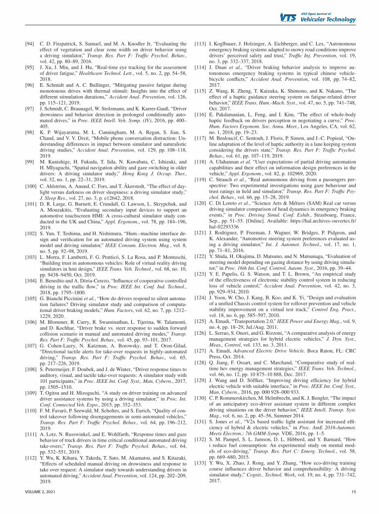
[94] C. D. Fitzpatrick, S. Samuel, and M. A. Knodler Jr, “Evaluating theeffect of vegetation and clear zone width on driver behavior usinga driving simulator,” Transp. Res. Part F: Traffic Psychol. Behav.,vol. 42, pp. 80–89, 2016.
[95] J. Xu, J. Min, and J. Hu, “Real-time eye tracking for the assessmentof driver fatigue,” Healthcare Technol. Lett., vol. 5, no. 2, pp. 54–58,2018.
[96] E. Schmidt and A. C. Bullinger, “Mitigating passive fatigue duringmonotonous drives with thermal stimuli: Insights into the effect ofdifferent stimulation durations,” Accident Anal. Prevention, vol. 126,pp. 115–121, 2019.
[97] J. Schmidt, C. Braunagel, W. Stolzmann, and K. Karrer-Gauß, “Driverdrowsiness and behavior detection in prolonged conditionally auto-mated drives,” in Proc. IEEE Intell. Veh. Symp. (IV), 2016, pp. 400–405.
[98] K. P. Wijayaratna, M. L. Cunningham, M. A. Regan, S. Jian, S.Chand, and V. V. Dixit, “Mobile phone conversation distraction: Un-derstanding differences in impact between simulator and naturalisticdriving studies,” Accident Anal. Prevention, vol. 129, pp. 108–118,2019.
[99] M. Kunishige, H. Fukuda, T. Iida, N. Kawabata, C. Ishizuki, andH. MIyaguchi, “Spatial navigation ability and gaze switching in olderdrivers: A driving simulator study,” Hong Kong J. Occup. Ther.,vol. 32, no. 1, pp. 22–31, 2019.
[100] C. Ahlström, A. Anund, C. Fors, and T. Akerstedt, “The effect of day-light versus darkness on driver sleepiness: a driving simulator study,”J. Sleep Res., vol. 27, no. 3, p. e12642, 2018.
[101] D. R. Large, G. Burnett, E. Crundall, G. Lawson, L. Skrypchuk, andA. Mouzakitis, “Evaluating secondary input devices to support anautomotive touchscreen HMI: A cross-cultural simulator study con-ducted in the UK and China,” Appl. Ergonom., vol. 78, pp. 184–196,2019.
[102] S. Yun, T. Teshima, and H. Nishimura, “Hum.–machine interface de-sign and verification for an automated driving system using systemmodel and driving simulator,” IEEE Consum. Electron. Mag., vol. 8,no. 5, pp. 92–98, 2019.
[103] L. Morra, F. Lamberti, F. G. Pratticó, S. La Rosa, and P. Montuschi,“Building trust in autonomous vehicles: Role of virtual reality drivingsimulators in hmi design,” IEEE Trans. Veh. Technol., vol. 68, no. 10,pp. 9438–9450, Oct. 2019.
[104] E. Benedito and A. Dòria-Cerezo, “Influence of cooperative-controlleddriving in the traffic flow,” in Proc. IEEE Int. Conf. Ind. Technol.,2018, pp. 1795–1800.
[105] G. Bianchi Piccinini et al., “How do drivers respond to silent automa-tion failures? Driving simulator study and comparison of computa-tional driver braking models,” Hum. Factors, vol. 62, no. 7, pp. 1212–1229, 2020.
[106] M. Blommer, R. Curry, R. Swaminathan, L. Tijerina, W. Talamonti,and D. Kochhar, “Driver brake vs. steer response to sudden forwardcollision scenario in manual and automated driving modes,” Transp.Res. Part F: Traffic Psychol. Behav., vol. 45, pp. 93–101, 2017.
[107] G. Cohen-Lazry, N. Katzman, A. Borowsky, and T. Oron-Gilad,“Directional tactile alerts for take-over requests in highly-automateddriving,” Transp. Res. Part F: Traffic Psychol. Behav., vol. 65,pp. 217–226, 2019.
[108] S. Petermeijer, F. Doubek, and J. de Winter, “Driver response times toauditory, visual, and tactile take-over requests: A simulator study with101 participants,” in Proc. IEEE Int. Conf. Syst., Man, Cybern., 2017,pp. 1505–1510.
[109] T. Ogitsu and H. Mizoguchi, “A study on driver training on advanceddriver assistance systems by using a driving simulator,” in Proc. Int.Conf. Connected Veh. Expo., 2015, pp. 352–353.
[110] F. M. Favarò, P. Seewald, M. Scholtes, and S. Eurich, “Quality of con-trol takeover following disengagements in semi-automated vehicles,”Transp. Res. Part F: Traffic Psychol. Behav., vol. 64, pp. 196–212,2019.
[111] A. Lotz, N. Russwinkel, and E. Wohlfarth, “Response times and gazebehavior of truck drivers in time critical conditional automated drivingtake-overs,” Transp. Res. Part F: Traffic Psychol. Behav., vol. 64,pp. 532–551, 2019.
[112] Y. Wu, K. Kihara, Y. Takeda, T. Sato, M. Akamatsu, and S. Kitazaki,“Effects of scheduled manual driving on drowsiness and response totake over request: A simulator study towards understanding drivers inautomated driving,” Accident Anal. Prevention, vol. 124, pp. 202–209,2019.
[113] I. Koglbauer, J. Holzinger, A. Eichberger, and C. Lex, “Autonomousemergency braking systems adapted to snowy road conditions improvedrivers’ perceived safety and trust,” Traffic Inj. Prevention, vol. 19,no. 3, pp. 332–337, 2018.
[114] J. Duan et al., “Driver braking behavior analysis to improve au-tonomous emergency braking systems in typical chinese vehicle-bicycle conflicts,” Accident Anal. Prevention, vol. 108, pp. 74–82,2017.
[115] Z. Wang, R. Zheng, T. Kaizuka, K. Shimono, and K. Nakano, “Theeffect of a haptic guidance steering system on fatigue-related driverbehavior,” IEEE Trans. Hum.-Mach. Syst., vol. 47, no. 5, pp. 741–748,Oct. 2017.
[116] E. Pakdamanian, L. Feng, and I. Kim, “The effect of whole-bodyhaptic feedback on drivers perception in negotiating a curve,” Proc.Hum. Factors Ergonom. Soc. Annu. Meet., Los Angeles, CA, vol. 62,no. 1, 2018, pp. 19–23.
[117] M. Benloucif, C. Sentouh, J. Floris, P. Simon, and J.-C. Popieul, “On-line adaptation of the level of haptic authority in a lane keeping systemconsidering the drivers state,” Transp. Res. Part F: Traffic Psychol.Behav., vol. 61, pp. 107–119, 2019.
[118] A. Ulahannan et al. “User expectations of partial driving automationcapabilities and their effect on information design preferences in thevehicle,” Appl. Ergonom., vol. 82, p. 102969, 2020.
[119] C. Strauch et al., “Real autonomous driving from a passengers per-spective: Two experimental investigations using gaze behaviour andtrust ratings in field and simulator,” Transp. Res. Part F: Traffic Psy-chol. Behav., vol. 66, pp. 15–28, 2019.
[120] C. Di Loreto et al., “Science Arts & Métiers (SAM) Real car versusdriving simulator comparison of head dynamics in emergency brakingevents,” in Proc. Driving Simul. Conf. Exhib., Strasbourg, France,Sep., pp. 51–55. [Online]. Available: https://hal.archives-ouvertes.fr/hal-02293336
[121] J. Rodriguez, P. Freeman, J. Wagner, W. Bridges, P. Pidgeon, andK. Alexander, “Automotive steering system preferences evaluated us-ing a driving simulator,” Int. J. Automot. Technol., vol. 17, no. 1,pp. 71–81, 2016.
[122] Y. Shida, H. Okajima, D. Matsuno, and N. Matsunaga, “Evaluation ofsteering model depending on gazing distance by using driving simula-tor,” in Proc. 16th Int. Conf. Control, Autom. Syst., 2016, pp. 39–44.
[123] Y. E. Papelis, G. S. Watson, and T. L. Brown, “An empirical studyof the effectiveness of electronic stability control system in reducingloss of vehicle control,” Accident Anal. Prevention, vol. 42, no. 3,pp. 929–934, 2010.
[124] J. Yoon, W. Cho, J. Kang, B. Koo, and K. Yi, “Design and evaluationof a unified Chassis control system for rollover prevention and vehiclestability improvement on a virtual test track,” Control Eng. Pract.,vol. 18, no. 6, pp. 585–597, 2010.
[125] A. Emadi, “Transportation 2.0,” IEEE Power and Energy Mag., vol. 9,no. 4, pp. 18–29, Jul./Aug. 2011.
[126] L. Serrao, S. Onori, and G. Rizzoni, “A comparative analysis of energymanagement strategies for hybrid electric vehicles,” J. Dyn. Syst.,Meas., Control, vol. 133, no. 3, 2011.
[127] A. Emadi, Advanced Electric Drive Vehicle. Boca Raton, FL: CRCPress, Oct. 2014.
[128] Q. Jiang, F. Ossart, and C. Marchand, “Comparative study of real-time hev energy management strategies,” IEEE Trans. Veh. Technol.,vol. 66, no. 12, pp. 10 875–10 888, Dec. 2017.
[129] J. Wang and D. Söffker, “Improving driving efficiency for hybridelectric vehicle with suitable interface,” in Proc. IEEE Int. Conf. Syst.,Man, Cybern., 2016, pp. 000 928–000 933.
[130] C. P. Rommerskirchen, M. Helmbrecht, and K. J. Bengler, “The impactof an anticipatory eco-driver assistant system in different complexdriving situations on the driver behavior,” IEEE Intell. Transp. Syst.Mag., vol. 6, no. 2, pp. 45–56, Summer 2014.
[131] S. Jones et al., “V2x based traffic light assistant for increased effi-ciency of hybrid & electric vehicles,” in Proc. AmE 2016-Automot.Meets Electron.; 7th GMM-Symp. VDE, 2016, pp. 1–5.
[132] S. M. Pampel, S. L. Jamson, D. L. Hibberd, and Y. Barnard, “Howi reduce fuel consumption: An experimental study on mental mod-els of eco-driving,” Transp. Res. Part C: Emerg. Technol., vol. 58,pp. 669–680, 2015.
[133] Y. Wu, X. Zhao, J. Rong, and Y. Zhang, “How eco-driving trainingcourse influences driver behavior and comprehensibility: A drivingsimulator study,” Cognit., Technol. Work, vol. 19, no. 4, pp. 731–742,2017.
VOLUME 2, 2021 15

BRUCK ET AL.: REVIEW OF DRIVING SIMULATION TECHNOLOGY AND APPLICATIONS
[134] A. Jamson, D. L. Hibberd, and N. Merat, “The design of haptic gaspedal feedback to support eco-driving,” in Proc. 7th Int. Driving Symp.Hum. Factors Driver Assessment, Training, Veh. Des., Univ. Iowa,2013, pp. 264–270.
[135] D. Kok, M. Knowles, and A. Morris, “Building a driving simulatoras an electric vehicle hardware development tool,” in Proc. DrivingSimul. Conf., Paris, France, Sep. 2012, pp. 1–7.
[136] D. H. Phuc, P. Rasincharoensak, and M. Nagai, “Study on driver modelfor hybrid truck based on driving simulator experimental results,”IATSS Res., vol. 42, no. 1, pp. 18–23, 2018.
[137] E. Baumgartner, A. Ronellenfitsch, H.-C. Reuss, and D. Schramm,“Using a dynamic driving simulator for perception-based powertraindevelopment,” Transp. Res. Part F: Traffic Psychol. Behav., vol. 61,pp. 281–290, 2019.
[138] X. Wang, X. Wang, B. Cai, and J. Liu, “Combined alignment effectson deceleration and acceleration: a driving simulator study,” Transp.Res. Part C: Emerg. Technol., vol. 104, pp. 172–183, 2019.
[139] A. J. Filtness et al., “Safety implications of co-locating road signs: Adriving simulator investigation,” Transp. Res. Part F: Traffic Psychol.Behav., vol. 47, pp. 187–198, 2017.
[140] M.-W. Kang and S. U. Momtaz, “Assessment of driver complianceon roadside safety signs with auditory warning sounds generated frompavement surface–a driving simulator study,” J. Traffic Transp. Eng.(English edition), vol. 5, no. 1, pp. 1–13, 2018.
LUCAS BRUCK (Student Member, IEEE) receivedthe B.S. degree in mechanical engineering fromthe Federal University of Sao Joao del-Rei, Brazil(UFSJ), in 2014. In 2018, he was with the Mc-Master Automotive Resource Centre (MARC),Mcmaster University as a M.S. Student. Lucas iscurrently working toward the Ph.D. degree withthe same university. In the following five years,he gathered experience in industry working withvehicle dynamics, virtual simulation, and testing.His main field of expertise is vehicle dynamics,
active controls and safety systems.
BRUCE HAYCOCK is a Scientist and the LeadEngineer for real-time computing with the Chal-lenging Environment Assessment Laboratory. Heis an Assistant Professor with the University ofToronto Institute for Aerospace Studies. Brucesbackground and research interests focus is primar-ily human-in-the-loop vehicle simulation, includ-ing simulator technologies, vehicle dynamics, andhuman control of vehicles. This experience is nowbeing applied at the unique simulation facilities,TRI to enable a broad range of research, notably
through the development and optimization of DriverLab and control of theCEAL hardware.
ALI EMADI (Fellow, IEEE) received the B.S. andM.S. degrees in electrical engineering with highestdistinction from the Sharif University of Technol-ogy, Tehran, Iran, in 1995 and 1997, respectively,and the Ph.D. degree in electrical engineering fromTexas A&M University, College Station, TX, USA,in 2000. He is the Canada Excellence ResearchChair Laureate with McMaster University, Hamil-ton, Ontario, Canada. He is also the holder of theNSERC/FCA Industrial Research Chair in electri-fied powertrains and Tier I Canada Research Chair
in transportation electrification and smart mobility. Before joining McMasterUniversity, Dr. Emadi was the Harris Perlstein Endowed Chair Professorof Engineering and Director of the Electric Power and Power ElectronicsCenter and Grainger Laboratories with the Illinois Institute of Technologyin Chicago, where he established research and teaching facilities as well ascourses in power electronics, motor drives, and vehicular power systems.He was the Founder, Chairman, and President of Hybrid Electric VehicleTechnologies, Inc. (HEVT) - a university spin-off company of Illinois Tech.Currently, he is the President and Chief Executive Officer with Enedym Inc.and Menlolab Inc.two McMaster University spin-off companies. He is thePrincipal Author/Co-Author of over 500 journal and conference papers aswell as several books including Vehicular Electric Power Systems (2003),Energy Efficient Electric Motors (2004), Uninterruptible Power Supplies andActive Filters (2004), Modern Electric, Hybrid Electric, and Fuel Cell Vehi-cles (2nd ed, 2009), and Integrated Power Electronic Converters and DigitalControl (2009). He is also the Editor of the Handbook of Automotive PowerElectronics and Motor Drives (2005) and Advanced Electric Drive Vehicles(2014). He is the Co-Editor of the Switched Reluctance Motor Drives (2018).Dr. Emadi was the Inaugural General Chair of the 2012 IEEE TransportationElectrification Conference and Expo (ITEC) and has chaired several IEEE andSAE conferences in the areas of vehicle power and propulsion. He was thefounding Editor-in-Chief of the IEEE TRANSACTIONS ON TRANSPORTATION
ELECTRIFICATION from 2014 to 2020.
16 VOLUME 2, 2021