ieee transactions on power electronics, …profs.hut.ac.ir/~naghizadeh/pe1 93-2 term...
TRANSCRIPT
IEEE TRANSACTIONS ON POWER ELECTRONICS, VOL. 23, NO. 2, MARCH 2008 771
Transformer-Coupled Multiport ZVS BidirectionalDC–DC Converter With Wide Input Range
Haimin Tao, Andrew Kotsopoulos, Jorge L. Duarte, Member, IEEE, and Marcel A. M. Hendrix, Member, IEEE
Abstract—Multiport dc–dc converters are particularly inter-esting for sustainable energy generation systems where diversesources and storage elements are to be integrated. This paperpresents a zero-voltage switching (ZVS) three-port bidirectionaldc–dc converter. A simple and effective duty ratio control methodis proposed to extend the ZVS operating range when input volt-ages vary widely. Soft-switching conditions over the full operatingrange are achievable by adjusting the duty ratio of the voltageapplied to the transformer winding in response to the dc voltagevariations at the port. Keeping the volt-second product (half-cyclevoltage-time integral) equal for all the windings leads to ZVSconditions over the entire operating range. A detailed analysisis provided for both the two-port and the three-port converters.Furthermore, for the three-port converter a dual-PI-loop basedcontrol strategy is proposed to achieve constant output voltage,power flow management, and soft-switching. The three-port con-verter is implemented and tested for a fuel cell and supercapacitorsystem.
Index Terms—Bidirectional converters, fuel cells, multiport con-verters, soft-switching, supercapacitors, three-port converters.
I. INTRODUCTION
MULTIPORT converters, a promising concept for alterna-tive energy systems, have attracted increasing research
interest recently [1]–[8]. Compared with the conventionalapproach that uses multiple converters, a multiport converterpromises cost-effective, flexible, and more efficient energyprocessing by utilizing only a single power stage.
For dc–dc power conversion, the dual-active-bridge (DAB)converter (Fig. 1) has been proposed in [9]. It has attractivefeatures such as low device stresses, bidirectional power flow,fixed-frequency operation, and utilization of the transformerleakage inductance as the energy transfer element. The maindrawback of the DAB converter, however, is that it cannothandle a wide input voltage range (e.g., fuel cells and superca-pacitors). In such a case the soft-switching region of operationwill be significantly reduced [9], [10].
Manuscript received July 19, 2005; revised April 27, 2007. This work wassupported by the Dutch funding agency for university research—the technologyfoundation STW. Recommended for publication by Associate Editor K. Ngo.
H. Tao was with the Electrical Engineering Department, Eindhoven Uni-versity of Technology, Eindhoven 5600 MB, The Netherlands and is nowwith Philips Lighting B.V., Eindhoven 5600, The Netherlands (e-mail:[email protected])
J. L. Duarte and M. A. M. Hendrix are with the Electrical Engineering Depart-ment, Eindhoven University of Technology, Eindhoven 5600 MB, The Nether-lands (e-mail: [email protected]; [email protected]).
A. Kotsopoulos is with the ANCA Pty., Ltd., Bayswater North VIC 3153,Australia (e-mail: [email protected]).
Digital Object Identifier 10.1109/TPEL.2007.915129
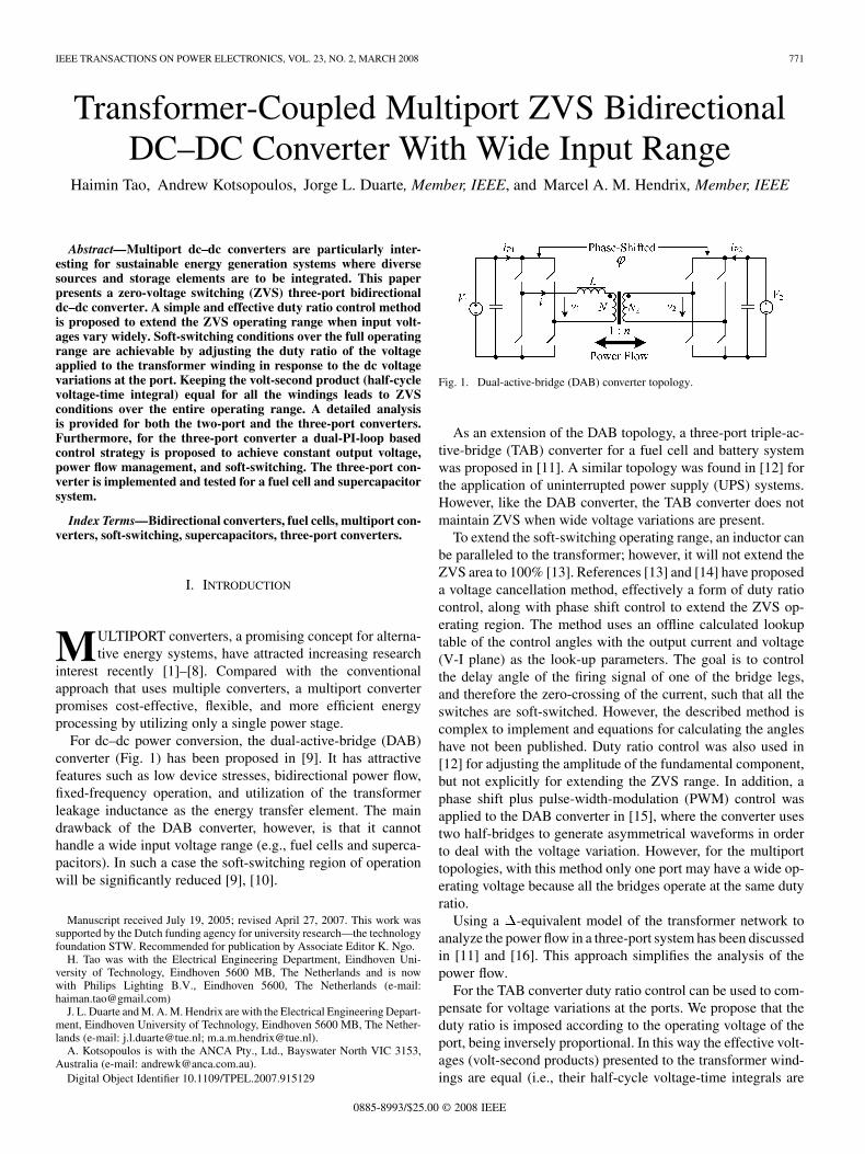
Fig. 1. Dual-active-bridge (DAB) converter topology.
As an extension of the DAB topology, a three-port triple-ac-tive-bridge (TAB) converter for a fuel cell and battery systemwas proposed in [11]. A similar topology was found in [12] forthe application of uninterrupted power supply (UPS) systems.However, like the DAB converter, the TAB converter does notmaintain ZVS when wide voltage variations are present.
To extend the soft-switching operating range, an inductor canbe paralleled to the transformer; however, it will not extend theZVS area to 100% [13]. References [13] and [14] have proposeda voltage cancellation method, effectively a form of duty ratiocontrol, along with phase shift control to extend the ZVS op-erating region. The method uses an offline calculated lookuptable of the control angles with the output current and voltage(V-I plane) as the look-up parameters. The goal is to controlthe delay angle of the firing signal of one of the bridge legs,and therefore the zero-crossing of the current, such that all theswitches are soft-switched. However, the described method iscomplex to implement and equations for calculating the angleshave not been published. Duty ratio control was also used in[12] for adjusting the amplitude of the fundamental component,but not explicitly for extending the ZVS range. In addition, aphase shift plus pulse-width-modulation (PWM) control wasapplied to the DAB converter in [15], where the converter usestwo half-bridges to generate asymmetrical waveforms in orderto deal with the voltage variation. However, for the multiporttopologies, with this method only one port may have a wide op-erating voltage because all the bridges operate at the same dutyratio.
Using a -equivalent model of the transformer network toanalyze the power flow in a three-port system has been discussedin [11] and [16]. This approach simplifies the analysis of thepower flow.
For the TAB converter duty ratio control can be used to com-pensate for voltage variations at the ports. We propose that theduty ratio is imposed according to the operating voltage of theport, being inversely proportional. In this way the effective volt-ages (volt-second products) presented to the transformer wind-ings are equal (i.e., their half-cycle voltage-time integrals are
0885-8993/$25.00 © 2008 IEEE
772 IEEE TRANSACTIONS ON POWER ELECTRONICS, VOL. 23, NO. 2, MARCH 2008
equal). In multiport topologies it is therefore possible to extendthe ZVS operating range to the entire operating region. Notethat although both are a form of duty ratio control, the proposedmethod (keeping the volt-seconds equal) is different from themethod presented in [13] and [14]. The way in which the dutyratio is controlled is essentially different.
An embodiment of the idea is a fuel cell system using a three-port converter. The implementation of a fuel cell system needsenergy storage to improve the system dynamics. A supercapac-itor has an advantage over batteries in terms of transient energystorage because it can be recharged and discharged virtually un-limited times, and the state-of-charge (SOC) of a supercapacitoris simply a function of the voltage. However, the supercapac-itor operating voltage varies widely compared with batteries.To keep ZVS, duty ratio control is applied to the supercapac-itor bridge.
This paper elaborates on our previous work in [17] and [18].Presented in the following sections are the ZVS analysis for theDAB and TAB converters, the system modeling, dual-PI-loopcontrol strategy, soft start-up methods, as well as simulation andexperimental results.
II. TWO-PORT TOPOLOGY
A. DAB Converter With Duty Ratio Control
In the conventional DAB converter (Fig. 1), each bridge gen-erates a square-wave voltage. The two voltages and arephase-shifted with respect to each other with an angle to con-trol the amount of power flow through the inductor whichrepresents the sum of the primary-referred transformer leakageinductance and optional external inductor.
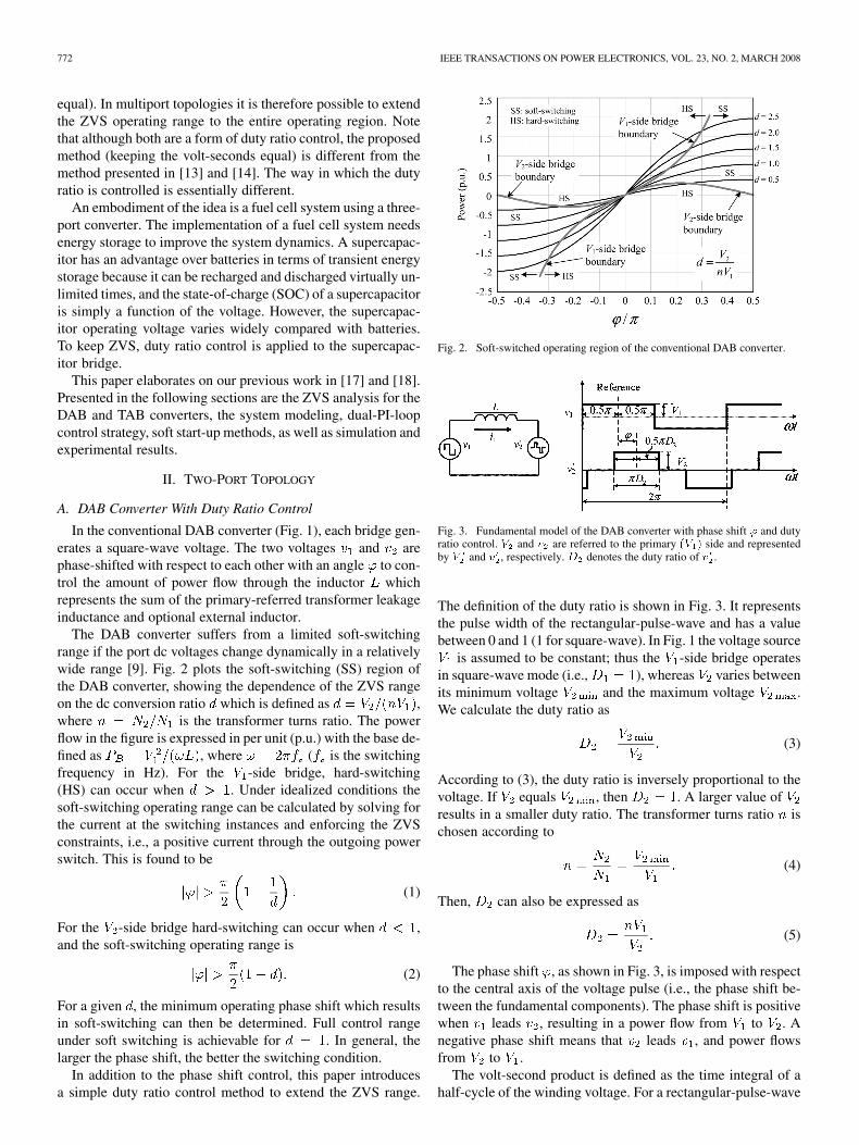
The DAB converter suffers from a limited soft-switchingrange if the port dc voltages change dynamically in a relativelywide range [9]. Fig. 2 plots the soft-switching (SS) region ofthe DAB converter, showing the dependence of the ZVS rangeon the dc conversion ratio which is defined as ,where is the transformer turns ratio. The powerflow in the figure is expressed in per unit (p.u.) with the base de-fined as , where ( is the switchingfrequency in Hz). For the -side bridge, hard-switching(HS) can occur when . Under idealized conditions thesoft-switching operating range can be calculated by solving forthe current at the switching instances and enforcing the ZVSconstraints, i.e., a positive current through the outgoing powerswitch. This is found to be
(1)
For the -side bridge hard-switching can occur when ,and the soft-switching operating range is
(2)
For a given , the minimum operating phase shift which resultsin soft-switching can then be determined. Full control rangeunder soft switching is achievable for . In general, thelarger the phase shift, the better the switching condition.
In addition to the phase shift control, this paper introducesa simple duty ratio control method to extend the ZVS range.
Fig. 2. Soft-switched operating region of the conventional DAB converter.
Fig. 3. Fundamental model of the DAB converter with phase shift ' and dutyratio control. V and v are referred to the primary (V ) side and representedby V and v , respectively. D denotes the duty ratio of v .
The definition of the duty ratio is shown in Fig. 3. It representsthe pulse width of the rectangular-pulse-wave and has a valuebetween 0 and 1 (1 for square-wave). In Fig. 1 the voltage source
is assumed to be constant; thus the -side bridge operatesin square-wave mode (i.e., ), whereas varies betweenits minimum voltage and the maximum voltage .We calculate the duty ratio as
(3)
According to (3), the duty ratio is inversely proportional to thevoltage. If equals , then . A larger value ofresults in a smaller duty ratio. The transformer turns ratio ischosen according to
(4)
Then, can also be expressed as
(5)
The phase shift , as shown in Fig. 3, is imposed with respectto the central axis of the voltage pulse (i.e., the phase shift be-tween the fundamental components). The phase shift is positivewhen leads , resulting in a power flow from to . Anegative phase shift means that leads , and power flowsfrom to .
The volt-second product is defined as the time integral of ahalf-cycle of the winding voltage. For a rectangular-pulse-wave

TAO et al.: TRANSFORMER-COUPLED MULTIPORT ZVS BIDIRECTIONAL DC–DC CONVERTER 773
Fig. 4. Possible operation modes at different phase shifts: (a) inner mode, and(b) and (c) outer mode. The shaded areas represent the volt-seconds of v andv .
voltage the integral simplifies to the product of pulse amplitudeand duty ratio .
With duty ratio control, the operation of the converter is thendivided into the inner mode and outer mode (see Fig. 4), whichis also described in [14]. To illustrate, Fig. 4 plots the idealizedvoltage and current waveforms . The ZVS condi-tions are summarized in the figure.
B. Inner Mode
The inner mode takes place when the phase shift is small andmeans that the span of the voltage pulse is within . Theinner mode occurs when , where is the boundarybetween the inner and outer mode:
(6)
In this mode the current waveform (indicated in Fig. 3)exhibits a double-pulse shape. As shown in Fig. 4(a), in the firsthalf period ( to ) tends to increase the inductor currentwhile tends to decrease it. If is controlled according to (5),the voltage-time integrals of and applied to the inductorare equal from to , that is
(7)
where is the switching period. This is represented by the twoshaded areas in Fig. 4(a). The difference between the inductorcurrent at the start and end of the half cycle is equal to zero.Furthermore, since the inductor current is symmetrical, (that is,
), together we have
(8)
Solving the above equation gives
(9)
Therefore, in the idealized circuit the -side bridge is criticallyzero-current switched (ZCS).
For the -side bridge, switching occurs at and .On the basis of (9), the current at the switching instants can bedetermined
(10)
Because and the current is symmetrical, we can con-clude that
(11)
Therefore, the ZVS conditions are confirmed.
C. Outer Mode
The right-outer mode and left-outer modeoccur when the phase shift is large. For Fig. 4(b), the an-
alytical expressions for the current at the commutating instantsare calculated to be
(12)
Because of the symmetry and the condition , we have
(13)
Therefore, the ZVS conditions for both - and -side are met.For the left-outer mode shown in Fig. 4(c), the same procedureapplies and the conditions can also be verified.
Provided that the volt-second product of is equal to thatof , ZVS conditions are automatically achieved in the outermode. In general, the switching condition is better in the outermode than in the inner mode.
D. Power Flow Calculation
In the DAB converter, without duty ratio control the powerflow is given by
(14)
where is in radians, showing a nonlinear dependency on thephase shift.

774 IEEE TRANSACTIONS ON POWER ELECTRONICS, VOL. 23, NO. 2, MARCH 2008
Fig. 5. Power flow versus phase shift in the DAB converter.
With the proposed duty ratio control method, the power flowis calculated to be
(15)
It is interesting to find that provided the transformer turnsratio is chosen according to (4) and the duty ratio is controlledby (5), the power flow for operation in the inner mode is a linearfunction of phase shift, while the power flow expression in theouter mode is nonlinear and complicated. Fig. 5 plots the powerversus phase shift at different duty ratios. Due to the duty ratiocontrol, less power is transferred at a given phase shift comparedwith that with only phase shift control.
III. THREE-PORT TOPOLOGY
A. TAB Converter With Duty Ratio Control
The proposed duty ratio control method is not ideally suitedfor the two-port DAB converter because it does not guaranteeZVS over the full range of operation (only critical ZCS in theinner mode). However, ZVS conditions can be achieved in thethree-port TAB converter.
Fig. 6 shows the topology of the converter for fuel celland supercapacitor applications and its simplified model withbridges replaced by voltage sources. This configuration isidentical to the TAB converter described in [11]. Conceptually,the circuit can be viewed as a network of inductors driven byvoltage sources with controlled phase shifts. The power flowin the system is controlled by the phase shifts. The transformeris represented by a -equivalent model to facilitate the systemanalysis [11]. The magnetizing inductance is neglected tosimplify the analysis.
With the proposed duty ratio control method, ZVS conditionsmay be achieved over the entire phase shift region. The volt-ages of the fuel cell and the load are assumed to remain con-stant because the load voltage is regulated and the fuel cellis supposed to operate at constant power hence at a near-fixedoperating voltage . However, the supercapacitor operatingvoltage varies widely. Duty ratio control is applied to the su-percapacitor side. Since the fuel cell and load side voltages arenear-constant, we have
(16)
The transformer turns ratios, as indicated in Fig. 6, are chosenaccording to (in case of all full-bridges)
(17)
where is the minimum operating voltage of the super-capacitor; and are the voltages of the fuel cell andthe load, respectively. Then, is controlled by
(18)
where is the supercapacitor operating voltage. The primary-referred amplitudes (peak values) of the voltages presented tothe transformer and inductor network, as indicated in Fig. 6(c),are (for a full-bridge circuit) given by
(19)
Therefore, the following is true:
(20)
Hence, the volt-second products of the three voltages applied tothe corresponding transformer windings are equal. The reasonwhy the converter is soft-switched lies in (20). This is explainedas follows.
B. Analysis of ZVS Conditions
Thanks to the -model representation, the system analysisis significantly simplified [11]. The three-port model is decom-posed into three two-port models. The idealized operating wave-forms of the TAB converter are illustrated in Fig. 7. Note thatthe waveforms vary with the operating point.
The ZVS condition for each bridge depends on the magni-tudes of the currents at the switching instants. This is summa-rized in Fig. 7, in other words, negative currents at the and
rising edges and positive currents at their falling edges. Ac-cording to the definitions of the reference direction in Fig. 6(b),the instantaneous currents in the three branches are given by
(21)

TAO et al.: TRANSFORMER-COUPLED MULTIPORT ZVS BIDIRECTIONAL DC–DC CONVERTER 775
Fig. 6. TAB converter for fuel cell and supercapacitor application, showing (a) the TAB topology, (b) the primary-referred �-equivalent model, and (c) voltagesgenerated by the three bridges shifted with ' and ' with v as the reference. The angles � and � are defined for control purposes. The currents i ; i and thevoltages v ; v represent the primary-referred values of i ; i ; v and v , respectively.
Based on the analysis of the two-port topology, and willbe exactly equal to zero at the switching (commutating) instantsof and under idealized conditions (both-inner mode), i.e.,
(22)
The voltage (fuel cell side) switches at and , while atthese two instants equals zero. Therefore, the current of thefuel cell side bridge at the switching instants is
(23)
So, does not contribute to the ZVS condition of the bridgenor does it make the switching condition worse. The turn-offcurrent of the bridge is only determined by in the case shown.Because is assumed to be equal to , the fuel cellside bridge is switched at zero-voltage in the entire phase shiftregion, as the optimal case in the DAB converter [9].
An equivalent situation occurs at the load side bridge. For thesupercapacitor side bridge, it switches under better ZVS condi-tions than the fuel cell and the load side bridges because both
and contribute current to drive the soft-switched transi-tion, as can be seen at and in Fig. 7.
For comparison, without duty ratio control hard-switchingoccurs at both the fuel cell and the load side bridge, as shown inFig. 7 (dashed lines).
Fig. 7. Idealized steady-state operating waveforms of the TAB converterwith and without duty ratio control in both-inner mode (D = 0:5; ' =0:1�; ' = 0:05�;L = L = L ).
Similarly, other operating modes such as a combination of theinner and outer mode, or both-outer mode can be analyzed based
776 IEEE TRANSACTIONS ON POWER ELECTRONICS, VOL. 23, NO. 2, MARCH 2008
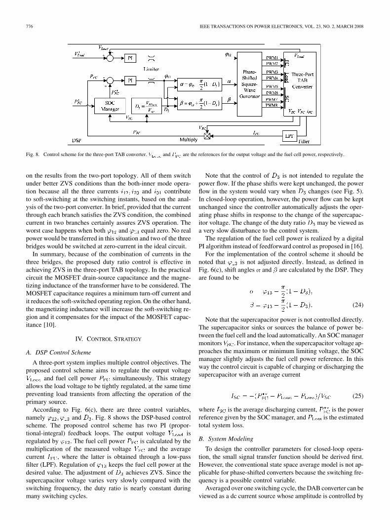
Fig. 8. Control scheme for the three-port TAB converter. V and P are the references for the output voltage and the fuel cell power, respectively.
on the results from the two-port topology. All of them switchunder better ZVS conditions than the both-inner mode opera-tion because all the three currents and contributeto soft-switching at the switching instants, based on the anal-ysis of the two-port converter. In brief, provided that the currentthrough each branch satisfies the ZVS condition, the combinedcurrent in two branches certainly assures ZVS operation. Theworst case happens when both and equal zero. No realpower would be transferred in this situation and two of the threebridges would be switched at zero-current in the ideal circuit.
In summary, because of the combination of currents in thethree bridges, the proposed duty ratio control is effective inachieving ZVS in the three-port TAB topology. In the practicalcircuit the MOSFET drain-source capacitance and the magne-tizing inductance of the transformer have to be considered. TheMOSFET capacitance requires a minimum turn-off current andit reduces the soft-switched operating region. On the other hand,the magnetizing inductance will increase the soft-switching re-gion and it compensates for the impact of the MOSFET capac-itance [10].
IV. CONTROL STRATEGY
A. DSP Control Scheme
A three-port system implies multiple control objectives. Theproposed control scheme aims to regulate the output voltage
and fuel cell power simultaneously. This strategyallows the load voltage to be tightly regulated, at the same timepreventing load transients from affecting the operation of theprimary source.
According to Fig. 6(c), there are three control variables,namely and . Fig. 8 shows the DSP-based controlscheme. The proposed control scheme has two PI (propor-tional-integral) feedback loops. The output voltage isregulated by . The fuel cell power is calculated by themultiplication of the measured voltage and the averagecurrent , where the latter is obtained through a low-passfilter (LPF). Regulation of keeps the fuel cell power at thedesired value. The adjustment of achieves ZVS. Since thesupercapacitor voltage varies very slowly compared with theswitching frequency, the duty ratio is nearly constant duringmany switching cycles.
Note that the control of is not intended to regulate thepower flow. If the phase shifts were kept unchanged, the powerflow in the system would vary when changes (see Fig. 5).In closed-loop operation, however, the power flow can be keptunchanged since the controller automatically adjusts the oper-ating phase shifts in response to the change of the supercapac-itor voltage. The change of the duty ratio may be viewed asa very slow disturbance to the control system.
The regulation of the fuel cell power is realized by a digitalPI algorithm instead of feedforward control as proposed in [16].
For the implementation of the control scheme it should benoted that is not adjusted directly. Instead, as defined inFig. 6(c), shift angles and are calculated by the DSP. Theyare found to be
(24)
Note that the supercapacitor power is not controlled directly.The supercapacitor sinks or sources the balance of power be-tween the fuel cell and the load automatically. An SOC managermonitors . For instance, when the supercapacitor voltage ap-proaches the maximum or minimum limiting voltage, the SOCmanager slightly adjusts the fuel cell power reference. In thisway the control circuit is capable of charging or discharging thesupercapacitor with an average current
(25)
where is the average discharging current, is the powerreference given by the SOC manager, and is the estimatedtotal system loss.
B. System Modeling
To design the controller parameters for closed-loop opera-tion, the small signal transfer function should be derived first.However, the conventional state space average model is not ap-plicable for phase-shifted converters because the switching fre-quency is a possible control variable.
Averaged over one switching cycle, the DAB converter can beviewed as a dc current source whose amplitude is controlled by
TAO et al.: TRANSFORMER-COUPLED MULTIPORT ZVS BIDIRECTIONAL DC–DC CONVERTER 777
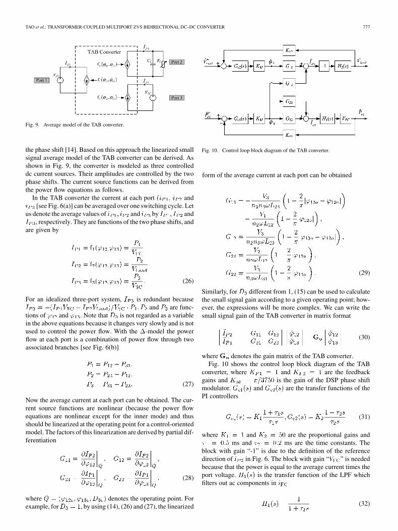
Fig. 9. Average model of the TAB converter.
the phase shift [14]. Based on this approach the linearized smallsignal average model of the TAB converter can be derived. Asshown in Fig. 9, the converter is modeled as three controlleddc current sources. Their amplitudes are controlled by the twophase shifts. The current source functions can be derived fromthe power flow equations as follows.
In the TAB converter the current at each port and[see Fig. 6(a)] can be averaged over one switching cycle. Let
us denote the average values of and by and, respectively. They are functions of the two phase shifts, and
are given by
(26)
For an idealized three-port system, is redundant becauseand are func-
tions of and . Note that is not regarded as a variablein the above equations because it changes very slowly and is notused to control the power flow. With the -model the powerflow at each port is a combination of power flow through twoassociated branches [see Fig. 6(b)]
(27)
Now the average current at each port can be obtained. The cur-rent source functions are nonlinear (because the power flowequations are nonlinear except for the inner mode) and thusshould be linearized at the operating point for a control-orientedmodel. The factors of this linearization are derived by partial dif-ferentiation
(28)
where denotes the operating point. Forexample, for , by using (14), (26) and (27), the linearized
Fig. 10. Control loop block diagram of the TAB converter.
form of the average current at each port can be obtained
(29)
Similarly, for different from 1, (15) can be used to calculatethe small signal gain according to a given operating point; how-ever, the expressions will be more complex. We can write thesmall signal gain of the TAB converter in matrix format
(30)
where denotes the gain matrix of the TAB converter.Fig. 10 shows the control loop block diagram of the TAB
converter, where and are the feedbackgains and is the gain of the DSP phase shiftmodulator. and are the transfer functions of thePI controllers
(31)
where and are the proportional gains andms and ms are the time constants. The
block with gain “-1” is due to the definition of the referencedirection of in Fig. 6. The block with gain “ ” is neededbecause that the power is equal to the average current times theport voltage. is the transfer function of the LPF whichfilters out ac components in
(32)

778 IEEE TRANSACTIONS ON POWER ELECTRONICS, VOL. 23, NO. 2, MARCH 2008
Fig. 11. Bode plot showing the open-loop gains of the system.
where ms is the time constant of the filter. is thetransfer function of the output capacitor and load (supposed tobe purely resistive)
(33)
where is the resistance of the load and F is thecapacitance of the output filter capacitor.
For the TAB converter the main control variables andcontrol the power flow in the system. In other words, two de-grees of freedom are available for the system control. Not sur-prisingly, the two PI control loops are coupled and influenceeach other as can be seen from Fig. 10. The bandwidth of theoutput voltage control loop is set higher than that ofthe power control loop in order to guarantee a fast re-sponse to variations in load. In this manner the interaction can beminimized. One can regard the former controller as the masterand the latter as the slave. This decoupling method is straightfor-ward to implement. Fig. 11 plots the open-loop Bode plot of thetwo control loops, showing different crossover frequencies. Theplotted transfer functions, using the parameters given above, are
(34)
A further improvement would employ a decoupling networkthat eliminates the interaction effects. In theory, the decouplingmatrix is the inverse matrix of the TAB converter gain matrix
(i.e., [12].
C. Methods for Soft Start-Up
Over-current at start-up is a drawback in both DAB and TABconverters. For instance, in the DAB converter the load side ca-pacitor is charged from zero at start-up, while the source side isat its normal operating level. As a result, the current waveform istriangular having a high peak value. Furthermore, the load sidebridge is hard-switched during this stage.
An easy way to avoid the over-current is to control the dutyratio of the source side bridge during start-up. Meanwhile theload side bridge is uncontrolled, effectively being a rectifier. Byincreasing the duty ratio gradually from zero to a certain value
with open-loop control, the load side capacitor can be slowlycharged to an operational level. Then, the closed-loop controltakes over to regulate the output voltage. Note that the loadshould be disconnected from the output filter capacitor duringthe start-up procedure. For the TAB converter, the same pro-cedure applies. A second method is to operate the converter ata higher frequency during the start-up. Because the impedanceof inductor becomes higher at a higher frequency, the currentis limited. In addition, a buck-boost start-up procedure for theTAB converter was discussed in [19].
V. SIMULATION AND EXPERIMENTAL RESULTS
A. Simulation Results
The TAB converter and its control scheme were simulatedwith PSIM. Parameters for the simulation are listed in Table I.Note that the fuel cell and load side bridges were implementedwith half-bridges because they operate in square-wave mode.Fig. 12 shows the simulation waveforms of the voltages and cur-rents in the three bridges in the cases of (a) a largeand (b) a small duty ratio. As can be observed fromFigs. 12(a) and 12(b), all the three bridges are soft-switched.On the contrary, in Fig. 12(c), without duty ratio control hard-switching occurs in two of the three bridges and the peak cur-rent is also much higher, where the operating parameters are thesame as in the case of Fig. 12(b).
To verify the dual-PI-loop control scheme, Fig. 13 illustratesthe power flow in the system in closed-loop operation, showingthe step changes in the load power (between 1 and 2 kW)in a time interval of 10 ms, while the fuel cell power re-mains constant after the transitions.
It is advisable not to set the duty ratio less than 0.5.Otherwise the higher peak current will decrease the efficiency.The minimum supercapacitor voltage can be set to half of therated/maximum voltage, i.e., a minimum duty ratio of 0.5. Fromthe energy point of view, three quarters of the energy storagecapacity of the supercapacitor is utilized because the energy isproportional to the square of the terminal voltage.
B. Experimental Results
The first laboratory prototype was rated at 1 kW maximumpower at 20 kHz. The switching frequency is restricted bythe resolution of the digitally implemented phase shift. It canbe increased when using an analog controller, a DSP withhigh-resolution PWM output (e.g., TMS320F2808 DSP) ortechniques such as dithering. A polymer electrolyte membrane(PEM) fuel cell with a maximum power 1 kW and a 145 Fsupercapacitor with a rated voltage of 42 V were used as thegenerator and storage, respectively. The fuel cell and loadside bridges were implemented with half-bridges, and thesupercapacitor side bridge was a full-bridge. Power MOSFETswere used as the switching devices for all the bridges. In theexperimental prototype, the inductances are somewhat higherthan the ones in the simulated circuit.
Fig. 14 and Fig. 15 show the mea-sured voltages and generated by the bridges and thecurrents and through the transformer windings. It canbe observed that the peak current is high when the duty ratio is

TAO et al.: TRANSFORMER-COUPLED MULTIPORT ZVS BIDIRECTIONAL DC–DC CONVERTER 779
Fig. 12. Simulation results of the TAB converter at ' = 0:1� and ' =
0:05�, showing soft-switching with duty ratio control at (a) D = 1 and (b)D = 0:5, and (c) hard-switching when not using duty ratio control at thesupercapacitor side. Note that all waveforms are referred to the primary and thecurrent waveforms are scaled.
small. Because of soft-switching, in both operating conditionsthe waveforms are clean and free of ringing.
Furthermore, system power flow control in response to apulsating load under the closed-loop operation is illustrated in
TABLE ISYSTEM SIMULATION PARAMETERS
Fig. 13. Simulation results of the power flow control in response to stepchanges in the load.
Fig. 16. The current (power) delivered by the fuel cell remainsunchanged after the transients and the load variations arecompensated for by the supercapacitor.
A second prototype rated at 3.5 kW and 100 kHz switchingfrequency using all full-bridges was also successfully tested[20]. In this case the control scheme was implemented with theTMS320F2808 DSP (using high-resolution phase shift).
VI. DISCUSSIONS
In fact, fuel cells have a reasonably wide operating voltagedepending on the output power. A duty ratio control method likethe one for the supercapacitor can be applied to the fuel cell side
(35)
where is the minimum operating voltage of the fuelcell. The transformer turns ratios are then chosen according tothe minimum operating voltages, i.e.,
(36)
It is possible to extend the three-port topology to an -porttopology—a multi-active-bridge dc–dc converter. According tothe proposed method, the transformer turns ratios are chosenaccording to the minimum operating voltages at the ports
(37)

780 IEEE TRANSACTIONS ON POWER ELECTRONICS, VOL. 23, NO. 2, MARCH 2008
Fig. 14. Experimental results of the TAB converter at ' = 0:1�; ' =
0:05� and D = 1, showing (a) the voltages generated by the bridges, and (b)the currents through the transformer windings.
where are the minimum operatingvoltages. The duty ratios are controlled with respect to the portoperating voltages
(38)
If the converter is controlled in this way, ZVS conditions forall the switches over the full operating region are theoreticallyachieved. The worst case is the critical ZCS. The advantage ofthe proposed duty ratio control method is that only a single di-vision is needed to calculate the duty ratio.
VII. CONCLUSION
Sustainable energy generators such as fuel cells and storagelike supercapacitors have a wide operating voltage range andtherefore present optimization challenges for power converters.Neither the DAB nor the TAB converter can operate with soft-switching over the full operating region when the input voltagevaries over a wide range. In addition to the primary power flowcontrol that is achieved by phase-shifting the bridges, a simpleand effective duty ratio control method has been proposed. Es-sentially, the latter aims to keep the volt-second product at eachtransformer winding equal. By adjusting the duty ratio of thevoltage presented to the winding inversely proportional to theport dc voltage, ZVS conditions are achievable over the full op-erating range.
The application of this control method in a fuel cell and su-percapacitor system has been analyzed. Duty ratio control is ap-plied to the supercapacitor bridge and, if required, to the fuel
Fig. 15. Experimental results of the TAB converter at ' = 0:1�;' =
0:05� and D = 0:5, showing (a) the voltages generated by the bridges, and(b) the currents through the transformer windings.
Fig. 16. Experimental results of the closed-loop power flow control of the TABconverter with the dual-PI-loop control scheme in response to step changes inthe load.
cell bridge to handle voltage variations while maintaining ZVS.The system was modeled and a DSP-based dual-PI-loop controlscheme was described in detail. This control scheme is straight-forward to implement. The closed-loop simulation and experi-mental results of a 1 kW prototype validate the effectiveness ofthe converter and control strategy.
REFERENCES
[1] B. G. Dobbs and P. L. Chapman, “A multiple-input dc–dc convertertopology,” IEEE Power Electron. Lett., vol. 1, no. 1, pp. 6–9, Mar. 2003.

TAO et al.: TRANSFORMER-COUPLED MULTIPORT ZVS BIDIRECTIONAL DC–DC CONVERTER 781
[2] N. D. Benavides and P. L. Chapman, “Power budgeting of a multiple-input buck-boost converter,” IEEE Trans. Power Electron, vol. 20, no.6, pp. 1303–1309, Nov. 2005.
[3] H. Tao, A. Kotsopoulos, J. L. Duarte, and M. A. M. Hendrix,“Multi-input bidirectional dc–dc converter combining DC-link andmagnetic-coupling for fuel cell systems,” in Proc. IEEE Ind. Appl.Soc. Conf. Annu. Meeting (IAS’05), Hong Kong, China, Oct. 2005,pp. 2021–2028.
[4] D. Liu and H. Li, “A ZVS bi-directional dc–dc converter for multipleenergy storage elements,” IEEE Trans. Power Electron, vol. 21, no. 5,pp. 1513–1517, Sep. 2006.
[5] H. Tao, A. Kotsopoulos, J. L. Duarte, and M. A. M. Hendrix, “Family ofmultiport bidirectional dc–dc converters,” Proc. Inst. Elect. Eng., vol.153, no. 3, pp. 451–458, May 2006.
[6] H. Tao, A. Kotsopoulos, J. L. Duarte, and M. A. M. Hendrix,“Triple-half-bridge bidirectional converter controlled by phaseshift and PWM,” in Proc. IEEE Appl. Power Electron. Conf. Expo(APEC’06), Dallas, TX, Mar. 2006, pp. 1256–1262.
[7] H. Al-Atrash, F. Tian, and I. Batarseh, “Tri-modal half-bridge convertertopology for three-port interface,” IEEE Trans. Power Electron., vol.22, no. 1, pp. 341–345, Jan. 2007.
[8] M. Marchesoni and C. Vacca, “New dc–dc converter for energy storagesystem interfacing in fuel cell hybrid electric vehicles,” IEEE Trans.Power Electron, vol. 22, no. 1, pp. 301–308, Jan. 2007.
[9] R. W. De Doncker, D. M. Divan, and M. H. Kheraluwala, “Athree-phase soft-switched high-power-density dc–dc converter forhigh-power applications,” IEEE Trans. Ind. Appl., vol. 27, no. 1, pp.63–73, Jan./Feb. 1991.
[10] M. H. Kheraluwala, R. W. Gascoigne, D. M. Divan, and E. D. Bau-mann, “Performance characterization of a high-power dual activebridge DC-to-DC converter,” IEEE Trans. Ind. Appl., vol. 28, no. 6,pp. 1294–1301, Nov./Dec. 1992.
[11] M. Michon, J. L. Duarte, M. Hendrix, and M. G. Simoes, “A three-portbi-directional converter for hybrid fuel cell systems,” in Proc. IEEEPower Electron. Spec. Conf. (PESC’04), Aachen, Germany, Jun. 2004,pp. 4736–4742.
[12] C. Zhao and J. W. Kolar, “A novel three-phase three-port UPS em-ploying a single high-frequency isolation transformer,” in Proc. IEEEPower Electron. Spec. Conf. (PESC’04), Aachen, Germany, Jun. 2004,pp. 4135–4141.
[13] K. Vangen, T. Melaa, S. Bergsmark, and R. Nilsen, “Efficient high-fre-quency soft-switched power converter with signal processor control,”in Proc. IEEE Telecommun. Energy Conf. (INTELEC’91), Nov. 1991,pp. 631–639.
[14] K. Vangen, T. Melaa, and A. K. Adnanes, “Soft-switched high-fre-quency, high power DC/AC converter with IGBT,” in Proc. IEEE PowerElectron. Spec. Conf. (PESC’92), Jun. 1992, pp. 26–33.
[15] D. Xu, C. Zhao, and H. Fan, “A PWM plus phase-shift control bidi-rectional dc–dc converter,” IEEE Trans. Power Electron, vol. 19, no. 3,pp. 666–675, May 2004.
[16] J. L. Duarte, M. Hendrix, and M. G. Simoes, “Three-port bidirectionalconverter for hybrid fuel cell systems,” IEEE Trans. Power Electron,vol. 22, no. 2, pp. 480–487, Mar. 2007.
[17] H. Tao, A. Kotsopoulos, J. L. Duarte, and M. A. M. Hendrix, “Asoft-switched three-port bidirectional converter for fuel cell and su-percapacitor applications,” in Proc. IEEE Power Electron. Spec. Conf.(PESC’05), Recife, Brazil, Jun. 2005, pp. 2487–2493.
[18] H. Tao, A. Kotsopoulos, J. L. Duarte, and M. A. M. Hendrix, “Designof a soft-switched three-port converter with 0DSP control for powerflow management in hybrid fuel cell systems,” in Proc. 11th Eur. Conf.Power Electron. Appl. (EPE’05), Dresden, Germany, Sep. 2005, pp.1–10.
[19] C. Zhao, S. Round, and J. W. Kolar, “Buck and boost start-up operationof a three-port power supply for hybrid vehicle applications,” in Proc.IEEE Power Electro. Spec. Conf. (PESC’05), Recife, Brazil, Jun. 2005,pp. 1851–1857.
[20] H. Tao, J. L. Duarte, and M. A. M. Hendrix, “High-resolution phaseshift and digital implementation of a fuel cell powered UPS system,”in Proc. 12th Eur. Conf. Power Electron. Appl. (EPE’07), Aalborg,Denmark, Sep. 2007, pp. 1–10.
Haimin Tao was born in China in 1976. He receivedthe B.S. degree in electrical engineering and theM.S. degree in power electronics from ZhejiangUniversity, Hangzhou, China, in 2000 and 2003, re-spectively, and the Ph.D. degree from the EindhovenUniversity of Technology (TU/e), Eindhoven, theNetherlands, in 2008.
From 2003 to 2004, he worked for Philips LightingElectronics, Shanghai, China. Between 2004 and2008, he carried out his Ph.D. research project at theTU/e. In January 2008, he joined Philips Lighting,
Eindhoven. His current interests include power electronic con verters anddigital control.
Andrew Kotsopoulos received the B.E. (withhonors) degree and the Ph.D. degree in electricaland computer systems engineering from MonashUniversity, Victoria, Australia, in 1992 and 1997,respectively. His Ph.D. thesis was in the area ofsoft-switched inverters.
After a period as a Research Assistant at Monashhe spent two years as a Research and DevelopmentEngineer for an Australian inverter manufacturer. Be-tween 2000 and 2005, he was with the Technical Uni-versity of Eindhoven, Eindhoven, The Netherlands,
as a Post-Doctoral Researcher in the Electrical Engineering Department. His re-search was related to power electronics in sustainable energy systems. In 2006,he joined ANCA Pty., Ltd., Bayswater North, Australia (a manufacturer of pre-cision tool making machines based in Melbourne), where he is leading the de-velopment of new servo drive products. His interests include power electronicconverters, digital signal processing and control systems.
Jorge L. Duarte (M’00) received the M.Sc. degreefrom the University of Rio de Janeiro, Rio de Janeiro,Brazil, in 1980 and the Dr.-Ing. degree from theInstitut National Polytechnique de Lorraine (INPL),Nancy, France, in 1985.
He has been with the Electromechanics and PowerElectronics Group, Technical University of Eind-hoven, Eindhoven, The Netherlands, as a Member ofthe Scientific Staff, since 1990. During 1989, he wasappointed a Research Engineer at Philips LightingCentral Development Laboratory, and since October
2000 he has also been a consultant Engineer at Philips Power Solutions,Eindhoven. His teaching and research interests include modeling, simulationand design optimization of power electronic systems.
Marcel A. M. Hendrix (M’98) received the M.S.degree in electronic circuit design from the Eind-hoven University of Technology (TU Eindhoven),Eindhoven, The Netherlands, in 1981.
He is a Senior Principal Engineer at PhilipsLighting, Eindhoven. In 1983, he joined PhilipsLighting, Eindhoven, and started to work in thePre-Development Laboratory, Business GroupLighting Electronics and Gear (BGLE&G). Sincethat time he has been involved in the design andspecification of switched power supplies for both
low and high pressure gas-discharge lamps. In July 1998, he was appointed apart-time Professor (UHD) with the Electromechanics and Power ElectronicsGroup, TU Eindhoven, where he teaches design-oriented courses in power elec-tronics below 2000 W. His professional interests are with cost function basedsimulation and sampled-data, nonlinear modeling, real-time programming, andembedded control.