i.l. 31-930-c instructions for type wli and wvb metal ... · i.l. 31-930-c instructions for type...
TRANSCRIPT

I.L. 31-930-C Instructions for Type WLI and WVB Metal Enclosed Switchgear (MVS) 5.0 kV, 15.0 kV, 25.8 kV, and 38.0 kV
Typical Outdoor and Indoor Units
Read and understand these instructions before attempting any Installation, Operation or Maintenance of this switchgear.
Effective June, 1993 Supersedes I.L. 31-930-B dated December, 1984

2
PURPOSE
This instruction book is expressly intended to cover the installation, operation and maintenance of type WLI and WVB metal enclosed switchgear. It does not purport to cover all possible contingencies, variations, and details that may arise during installation, operation or maintenance of this equipment.
TABLE OF CONTENTS Page
Section 1- Introduction ........................................... 3
1.0 Basic Description and Application 1.1 Switchgear Identification 1.2 Safety Features
-.L .;, o::1an; rnLcucg
Section 2 - Receiving, Handling and Storage ................ 4
2.0 Receiving 2.1 Handling 2.2 Storage
Section 3 - Installation ............................................ 4
3.0 Joining WLI Enclosures 3.1 Installation of Roof Caps on Outdoor Units 3.2 Conn. of WLI Switchgear to Transformer 3.3 Conn. to AMPGARD Starter Lineup 3.4 Connection to Metal Clad Switchgear Lineup 3.5 Connection of Customer Power Cable 3.6 Field Taping of Electrical Connections 3.7 Securing WLI switchgear to Foundation 3.8 Connection of Space Heaters to
Customers Source 3.9 Superstructure Assembly 3.10 Inspection Before Startup
Section 4 - Operation ............................................ 11
4.0 Safety Interlocks 4.1 ::>witcn uperanon 4.2 Fuse Replacement
Section 5 - Maintenance ..................................... 13
5.0 Inspection Schedule 5.1 Inspection Procedure 5 .2 Alignment Procedures 5.3 Replacement Procedures 5.4 Insulated Bus Maintenance 5.5 Lubrication
Section 6 - Selector Switch Configuration ................ 18 Section 7 - Duplex Configuration .......................... 18
Section 8 - Motor Operation ................................ 18
8.0 Description 8.1 Receiving and Startup 8.2 Electrical Operation 8.3 Safety Interlocking 8.4 Manual Operation 8.5 Maintenance
Section 9 - Electromechanical Stored Energy Release.19
9.0 Description 9 .1 Operation 9 .2 Door Interlock (Shaft Blocking Cam) 9.3 Inspection and Maintenance
Section 10 - WVB Switchgear .............................. 23
10.0 Description and Application 10.1 Identification 10.2 Safety Features 10.3 Receiving, Handling and Storage 10.4 Installation 10.5 Operation 10.6 Maintenance
Section 11 - Renewal Parts .................................. 26
FURTHER INFORMATION WLI Renewal Parts Data - RPO 31-935 WLI Descriptive Bulletin - DB 31-935 WVB Descriptive Bulletin - DB 31-960 Type VCP-W Vacuum Circuit Breaker
Instruction Book - IB 32-255-1 Type RBA Fuse - l.L. 36-654-lA

SECTION 1 - INTRODUCTION
1.0 Basic Description and Application
Type WLI and WVB metal enclosed switchgear consist of an air insulated, three pole, gang-operated, quick-make, quick-break, load interrupter switch in a floor mounted metal enclosure. It can be applied in combination with power fuses or a vacuum circuit breaker (WVB) and many other protectivie devices to provide safe, economical switching and circuit protection where infrequent disconnecting means is required.
1.1 Switch Modifications
A nameplate is located inside the small access door of each type WLI switchgear vertical section . Contained on this nameplate are the Cutler-Hammerorder number, drawing number, and switch style number. This information should be given to the Cutler-Hammer sales office if a question should arise concerning the switchgear or if renewal parts are required. These numbers allow the factory to completely identify the switchgear. Also located on the nameplate are voltage and current ratings for the swiccn ana swiccngear.
1.2 Safety Features
Type WLI load interrupter switchgear has several built-in features to reduce hazards and to provide proper operating sequences.
WARNING
Exceeding nameplate ratings of WLI switchgear could cause property damage, severe injury, or death. WLI
switchgear must be operated within its namcplated ratings.
3
1. A door interlock prevents opening the enclosure front door while the switch is in the closed position.
2. A switch interlock prevents manual operation of the handle mechanism with the door open.
3. A viewing window is provided to verify each switch contact position.
4. Facility is provided for padlocking the switch in the open or closed position.
5. Facilities are provided for padlocking the door handles closed.
6. Mechanical indicators show whether the switch mechanism is open or closed.
7. Key interlocks, when provided, force a sequence of operation.
CAUTION
Operating a WLI switch with a key interlock bolt extended will result in equipment damage and may
also expose a person to bodily injury or death. The key must be inserted into the interlock and
rotated to retract the locking bolt before operating a WLI switch.
1.3 Safe Practices
Only qualified electrical workers with training and experience on high voltage circuits should be permitted to work on this equipment. They should be familiar with the work to be performed, the safety equipment required, and hazards involved.
1. Read and understand these instructions before attempting any assembly, operation, or maintenance of this switchgear. Exceeding nameplate ratings of WLI switchgear could cause property damage, severe injury, or death.

4
2. Disconnect all power sources before making any adjustments or perfonning maintenance.
3. After opening switch and before opening door, use viewing window to insure that all three switch blades are open. If necessary, use a flashlight to verify all three contacts are open.
There are several interlocks on the switches. They are for personnel and/or equipment protection. Under no circumstances should they be made inoperative when switch is in service. To do so could cause bodily injury or property damage.
4. Never energize the switch without the arc chutes and barriers installed.
5. Always be sure that all hardware is in place and bolted tightly before putting switch into operation.
6. Before replacing covers, carefully inspect buswork and phase barriers to insure that no tools or other objects are accidently left inside the unit.
SECTION 2 - RECEIVING, HANDLING AND STORAGE
2.0 Receiving
A visual inspection - inside and out - should be perfonned immediately upon receipt of the switchgear and before removing it from the truck. Shipping papers should be checked to be sure all boxes or other accompanying pieces have been received. If any damage or shortages are evident, a claim should be filed at once with the carrier, and the nearest Westinghouse sales office notified.
The order data nameplate for each switch assembly is located inside or on the access door. The order number and drawing number are located on this nameplate and should be given to the Cutler-Hammer representative whenever identification of the assembly is required.
2.1 Handling
Removable lifting plates are provided on the top of the WLI or WVB structure for insertion of hooks to lift the complete structure. This is the only recommended method of moving the WLI or WVB structure. Extreme care should be used not to damage of defonn the unit if other moving methods are employed.
2.2 Storage
If it is necessary to store the equipment before installation, keep it in a clean, dry location with ample air circulation and heat to prevent condensation. Like all electrical apparatus, these units contain insulation which must be protected against dirt and moisture. OUTDOOR UNITS MAY BE STORED OUTSIDE ONLY IF ROOF CAPS ARE INSTALLED, SPACE HEATERS ENERGIZED, AND ANY OPENINGS ARE ENCLOSED.
SECTION 3 - INSTALLATION
Refer to shipping list (Fonn SUM-T-3) for location of bus, hardware and all other joining and installation material.
3.0 Joining Type WLI or WVB Enclosures
3.0.0 Access to WLI switch Vertical Sections Containing Switches
Each WLI switch is shipped from the factory in the closed position to maintain alignment during shipping and handling. The safety interlocking prevents opening of the door of the vertical section when the switch is closed. In order to gain access to the interior, be sure the switchgear is on a true and level surface. To open a manually operated WLI switch insert the operating handle and push down. When the switch opens the door may be opened. If the switch is equipped with an electro-mechanical stored energy release feature, follow the instructions on the label inside the small access door, starting at the section" switch closed, spring discharged" to open switch. If the switch is motor operated, open the motor compartment door where the motor operator is housed, remove handle, insert in the manual operating port and push down to open switch, being sure any key interlock bolts, if supplied, are retracted before attempting to operate the switch. If the switch is motor operated with the electromechanical stored energy release device, insert handle in operating port and push down. An audible "clunk" will be heard as the operating mechanism engages its release trigger. To access the trigger, it will benecessary to remove a small access cover on the side of the motor cabinet, then stick a screw driver or similar lever tool through the opening to lift the trigger.
When handling WLI switchgear, be sure the switches are in the closed position. Do not operate WLI switches unless they are setting on true and level surfaces.
3.0.1 Identification of Shipping Splits
Refer to the front view drawing. Below this drawing, shipping splits will be identified in relation to group numbers for each cubicle. Nonnally shipping sections will not exceed 154 inches in width.
3.0.2 Procedures for Joining WLI or WVB Enclosures at Shipping Splits (Refer to Fig. 2)

Cutout
t
c 0
111.!l!'IV--Mounting 1-------''1- Bolts
Fig. 2 Joining WLI Enclosures
a. Remove the eight 3/8 inch bolts from each side sheet.
b. Position the shipping sections next to each other. The eight holes will match holes in adjacent side sheets.
c. Bolt the side sheets together using the eight bolts removed from one side sheet.
d. Make main and ground bus connections using splice plates and hardware furnished. Bus bar is usually tin or silver plated. To insure a proper electrical connection, care should be taken to protect the plating from damage. DO NOT use joint compound.
CAUTION
Cleaning bus joints with abrasive or chemical cleansers may remove plating, which may cause
joint overheating. Wipe with clean, dry cloth to clean off surfaces.
e. Bolted connections should be tightened to the torque values given in Appendix A.
3.1 Installation of Roof Caps on Outdoor Units.
Roof caps are necessary to complete the roof of all outdoor WLI switchgear assemblies. Those not factory installed are shipped in cartons which may be put within one or more vertical sections if there is space, or they will be shipped separately. The following procedure and accompanying
5
figures detail the work to be done to install each cap.
a. Remove the lifting plates from the WLI assembly and replace the bolts.
b. Place a roof cap in position and start enough screws (provided loose in a hardware package) to temporarily hold it in place.
c. Draw a pencil line down the side(s) on to the roof to mark the edge(s) of the cap on the roof. (Fig. 3)
Fig. 3 Installation of Roof Caps on Outdoor Units
d. Remove roof cap and apply a 114" bead of caulking along the inside edge of the pencil line(s). (Tubes provided by Westinghouse loose)
e. Hold the edge of the roof cap adjacent to the pencil line, then rotate over onto the bead(s) of caulk, aligning with the bolt holes in the roof as the action is completed. (See Fig. 4)
f. Put in bolts and gasketed washers (rubber side towards roof cap) in every bolt hole of roof cap. Tighten the bolts to 5 ft-lbs.
g. Following instructions on the caulking container, smooth out any excess caulk along edges of the roof cap.
Continue this procedure until all roof caps have been installed.

6
Fig. 4 Roof Cap Insiallalion
3.2 Connection to Type WLI Switchgear to Transformer
3.2.1 Physical Connection
3.2.1.1 Indoor Assemblies
Holes are predrilled in the side of the WLI structure to match holes provided in the transformer.
3.2.1.2 Outdoor Throat Connection (See Fig. 5)
a. Switch and transformer should be brought together to give spacing ol" 112 inch between throat flanges.
b. Apply double adhesive tape supplied with WLI switchgear to outside surfaces of both flanges.
c. Press felt supplied with WLI switchgear into place on adhesive tape. Felt is to seal against entrance of dust and to prevent transmission of vibration produced by transformer resonance to the WLI switchgear.
d. Reinstall sealing ring removed prior to mating the flanges in "a" above.
3.2.2 Medium Voltage Electrical Connections
3.2.2.1 Connection by Cable Supplied with Type WLI Switch
a. Cables are not factory pre-cut to proper length. Installer !!!Jill cut to fit.
Removable Plate and Seal for Making Electrical Connections
Felt and Adhesive Tape
·------ : n Transformer Throat
:, ....... ~~+i---~-=-""-'-~ .... ~
H.V. Switch
H.V. Switch Throat
~ Sealing Section
¥2".J ~ Felt and Adhesive Tape
Fig. 5 Transformer Connection to WLI Switch
b. Since factory cables are unshielded, they must be properly separated from each other, from all grounded metal parts, and from transformer bushings/terminals of other phases.
c. Type WLI switchgear conforms to ANSI standards concerning phasing. Phases are arranged A, B, C, front to rear, top to bottom, and left to right at connection points unless otherwise noted on the drawings. The installer is responsible for maintaining continuity of phasing throughout the system.
d. Lugs are provided with the switchgear for terminating cable to the transformer bushings/terminals.
3.2.2.2 Connection by Bus Bar
a. Splice plates and hardware are furnished with the WLI switchgear.
b. Bus bar is tin or silver plated. To insure a proper electrical connection, care should be taken to protect the plating from damage. Refer to para 3.0.2.d.
c. All bolts should be tightened according to Appendix A.
3.3 Connections to AMPGARD Medium Voltage Motor Control Center.
a. Holes are predrilled in the side of the WLI switchgear structure to match holes provided in the MCC. Bolt together using hardware furnished with WLI switchgear.
b. Make bus connections per Section 3.2.2.2.

3.4 Connections to Metal Clad Switchgear Assembly
3.4.1 Indoor Switchgear - Follow Same Procedure Outlined in Section 3.3.
3.4.2 Outdoor Switchgear (See Fig. 6)
a. Position units side by side. Holes in WLI side sheet around bus cutout will match holes in metal clad switchgear flange.
b. Press sponge neoprene gasketing tape supplied with WLI on to flange for weather-tight seal.
c. Join enclosures using bolts supplied with WLI. Opposite side of metal clad switchgear flange has nuts welded in place for ease of connection.
d. Make bus connections per Section 3.2.2.2.
Metal Clad Switchgear
Gasket Supplied byWLI
Fig. 6 Connection to Metal Clad Switchgear Lineup -Outdoor Unit
7
3.S Connection of Customer Power Cables
Cable termination space is provided in the cubicle for top or bottom cable entry as shown on the drawings. Adequate electrical clearance must be maintained between cables, energized parts, and grounded metal parts. It is also the installer's responsibility to adequately support cables such that insulators or bus bars do not carry the strain of the cables.
Tin-plated aluminum clamp type terminals are supplied as standard and are suitable for acceptance of copper or aluminum cable. If potheads or other special terminations are supplied, termination should be made according to the terminator manufacturer's instructions.
3.6 Field Taping of Electrical Connections (See Fig. 7)
Field taping of electrical connections should be done where shown on drawings, or as tagged by the factory inspector. Taping materials are supplied with the WLI assembly.
Fig. 7 Field Taping of Electrical Connections
3.6.1 Materials
a. Filler - insulation putty b. Insulating tape - black, linerless H.V. EPR tape, 1"
wide.
3.6.2 Procedure
a. Clean area of dirt and foreign matter per Section 5.4.
b. Apply filler over bare conductor and hardware to cover and smooth out the surface. Blend contour into preinsulation surfaces. Cover conductors and hardware with at least 1/8" of filler.
c. Apply insulating tape, lapping and layering as specified in the chart. Tape must overlap factory installed insulation by 1". Elongate insulating tape 10 to 25 percent during

8
application to insure a smooth, tight fit. Should a tape roll be used up, start the new roll by overlapping any previous end by 112 tum.
Chart 1 Taping Oum
Lap of Tape No. of Layers
Up to S kV 1/2 1
Overs kV to 213 2 38 kv
3.6.3 Factory installed insulation may be NORYL, a highperformance engineering thermoplastic. It can be irreversibly damaged if it comes in contact with certain chemicals. See Section 5.4 for cleaning procedures.
WARNING
Use of solvents, oils, joint compounds, or greases on or near NORYL insulation will destroy it. Clean
only with water or isopropyl alcohol.
3. 7 Securing WLI or WVB Swit.chgear Assemblies to Foundations
All anchoring hardware and necessary devices are to be supplied by the installer.
3.7.1 Indoor units can be secured to the foundation using 1/2" anchor bolts. The four 518" holes in the base for these bolts are shown on the floor plan included with the drawings.
3. 7.2 Outdoor units are secured using clips and foundation bolts as shown Fig. 8. Lead anchors and lag screws may be used in place of J-bolts if desired.
3.8 Connection of Space Heaters to Customers Source
Space heaters, when supplied, must be energized to prevent condensation. Heaters are supplied for 120 or 240 volt sources as shown on drawings.
For single units with no heater control devices,(thermostats, circuit breakers, or safety switches), the installer must wire directly to terminals on the space heater.
For lineups or units with heater control devices, heaters will be internally wired and brought to a terminal block. A wiring diagram will be furnished with the drawings showing connection points for power.
11-9/16"1
r 4"
<;7 0
<J 0 <1
60
WLI Outdoor Base
Customer Tie Down Clip
\;'
<J "' "
0 !>
--· ("... \'
'V ' ' ' ' -
I 0 ; , ---
<:/ 1> . ¢
0 'V <:/
0
V' 0 . f> 0
F'ig. 8 Bolting WLI or WVB Unit to Foundation
2"
..:1 D
.
3.9 Superstructure assembly (See Figs. 9A and 9B)
3.9.1 Receiving
Check to see that all parts necessary for assembly have been received. The packing list will show all required items (bus, hardware, phase barriers, taping material, etc.) and will indicate in which shipping unit the various parts are located.
3.9.2 Installation of Superstructure
a. If a lineup, join per Section 3.0. Secure switches to foundation per Section 3.7.
b. Remove top sheet from switch unit. On indoor units this top sheet will later be re-installed on the superstructure using the same mounting hardware. Outdoor units are shipped with the roof attached to the superstructure. The top sheet on the switch is used for shipping purposes only, and may be discarded after removal.

1 - Roof Cap (O.D. Units Only)
2 - Bus Support Insulator 3 - Main Horizontal Bus 4 - Phase Bus Risers 5 - Upper Phase Barrier 6 - Nylon Separator Rod
7 - Lower Phase Barrier 8 - Nylon Bolts and Nuts 9 - Upper Switch Terminal
Pad 10 - Incoming Line Bus 11 - Incoming Cable
Termination
Fig. 9A Section View, Superstructure Assembly
-1-------r-
Q---'.-iL J
Fig. 9B Front View, Superstructure Assembly
I I L J
9
c. Remove lifting eyes and replace mounting bolts after removal.
d. Remove superstructure from the shipping pallet and then remove all bolts covers from it. Shipment of more than one WLI will be tagged to identify superstructures with their corresponding switch units. Install superstructure atop switch using the bolts, nuts, washers, and/or self tapping screws as provided. Occasionally the superstructure assembly will become slightly "sprung" in shipment so that it does not align exactly with the top of the switch enclosure. If this should occur, install bolts or screws in all holes that align then use a pinwrench to pry adjacent holes into alignment.
3.9.3 Bus assembly All bus sections have been assembled at the factory and checked for clearance prior to shipment.
a. Units without horizontal main bus require installation of one piece of bus section per phase from the upper switch terminal pad to the incoming line termination. Each phase bus is attached in two places-to the upper switch terminal pad and to the bus support insulator mounted in the superstructure. Use the bolts provided.
b. Units with main bus also require horizontal bus sections bolted to the bus support insulators. Phase bus risers are then bolted from the switch terminal pad to the main horizontal bus. Lineups shipped in more than one section will be supplied with horizontal bus lengths corresponding to widths of shipping sections. After installation, join horizontal bus sections using splice plates provided.
c. Tighten all bolted bus connections to torque values given in Appendix A.
d. Bus requiring field taping will be identified by a red taping tag. Taping material will be provided and taping procedures described in Section 3.6 should be followed.
3.9.4 Upper Phase Barrier Installation Remove upper nylon separator rod using "E" rings to secure to phase barriers. Barriers should be aligned straight and true with maximum clearance from live parts.
3.9.5 Replacing Covers
CAUTION
Before replacing covers, carefully inspect busworlc: and phase barriers to insure that no tools or other objects are accidentally left inside the unit.

10
a. Install roof and covers using hardware provided.
b. Install roof caps on outdoor units per Section 3.1.
3.10 Switch Inspection Before Startup
Each switch is properly adjusted at the factory before shipment. However, vibration and mechanical stresses imposed by transit and installation can adversely affect switch adjustment; therefore, a final inspection is essential before energizing. If this inspection reveals any defects in adjustment, they should be corrected according to alignment procedures in Section 5.2.
Fig. 10 Main Blade Adjustment
Inspection procedures require closing and opening the switch with the main door open. This requires override of the switch safety latch as described in Section 5.2.1 and must be accomplished before energization.
Inspection Procedure:
a. With switch in the open position(see Fig.10) the distance between the edge of the main blade and the closest point of the break jaw should be:
~SIB" -if- 118" for 5 kV switches ~314" -if- 118" for 15 kV switches
11-112" +I- 118" for 25 and 35 kV switches
b. Main and flicker blades must be in proper alignment with breakjaws and arc chute openings respectively. This can be checked by closing the switch and then partially
Main SW itch Shaft
Y1g. 11 Drive Rod I.inks and Shaft Ean Alignme111
opening it using the maintenance hub as described in Section 5 .1.3.
c. In the closed position the drive rod links and shaft ears must be 1116" to 118" over toggle when checked with a straight edge(see Fig. 11).
d. With the switch closed, the upper spacers of the main blades should rest 3/16" + 1116" above the bottom of the depression of the stationary break jaw (see Fig.12).

e. Check bolted bus connections for proper tightness, referring to Appendix A for torque values.
f. If fixed mounted fuses are supplied, check the plastic knobs that hold fuses in place. They should be hand tight.
g. If disconnect fuses are supplied, check to see that they are completely latched closed.
h. For units fitted with expulsion-type, boric acid fuses, check the discharge filters on the lower end of the fuses for tightness. They must be securely hand tightened.
i. Check to see the space heaters, if supplied, are energized.
j. Wipe away any dust or dirt that may have accumulated in compartment(s) paying particular attention to insulators and insulating material. If bus is insulated, see Section 5.4 for cleaning procedures.
k. A final thorough inspection should be made to insure that no tools or other objects are accidentally left inside the enc1osure.
SECTION 4 - OPERATION
4.0 MECHANICAL SAFETY INTERLOCKS
The WLI switch is equipped with switch interlocks and door interlocks as well as provisions for padlocking in either the open or closed position.
WARNING
Defeating or disengaging safety interlocks on a WLI switch that is connected to a power source may
result in property damage, bodily injury or death.
Do not defeat or disengage any safety interlocks.
4.0.1 Switch Interlock
This interlock prevents inadvertent closure of the switch if the enclosure door is open. When the door is closed, the pointed latch lug welded to the inside of the door causes tne satety Jatcn to move out of the blocking position(see Fig.13).
11
Fig. 13 Safety Latch Lacation
4.0.2 Door Interlock
This interlock prevents the door of the enclosure from being opened when the switch is closed. When the switch is closed, a cam welded to the operating shaft engages a bracket welded to the inside of the switch door, preventing the door from being opened.(See Fig.14.)
Fig. 14 Maintenance Hub Lacation

12
4.0.3 Key Interlocking
Key interlocks are supplied when specified. Certain WLI switchgear configurations require key interlocks and they are therefore included. Standard schemes are available for locking the switch in the open position or the closed position as well as locking the main door closed. Numerous other schemes are available for special requirements which can coordinate with upstream or downstream devices supplied by other Cutler-Hammer divisions or other equipment.
WARNING
Key interlocks, when supplied from the factory, will have a key for each lock; however, for correct sequence of operation, one or more of the keys must be eliminated. These excess keys must either be destroyed or locked awa) where they will not be accessible to operating personnel. Failure to do so may result in severe injury or death.
CAUTION
0po;;111u11~ .. -.vu switch with a key interlock bolt extended will result in equipment damage and may
also expose a person to bodily injury or death. The key must be inserted into the interlock and
rotated to retract the locking bolt before operating a WLI switch.
4.1. Switch Operation
To manually close or open the switch, the small access door must be opened and the operating handle withdrawn from the clips at the left side of the opening. The handle is inserted into the handle casting and rotated up or down as appropriate. This charges the compression spring, and as the spring lever goes over toggle, the stored energy of the spring is transferred to the shaft which snaps the switch open or closed. The blades thus move at a predetermined speed which is independent of the operator.
The quick-make mechanism provides power to overcome blowout forces which occur if the switch is closed into a fault. However, these forces are not transmitted to the operating handle since it is not rigidly connected to the blades. Therefore, the switch can be safely closed under short circuit conditions within its fault-close rating.
Load interruption is accomplished by a flicker blade and engaging contact fingers located inside a DE-ION arc chute. On opening the switch, the main blades open first and all current is shunted through the spring loaded flicker blades. Further travel of the main blades causes the flicker blades to snap out of their contact fingers where associated arcing takes place within the arc chutes.(See Fig.15 for sequence of operation.)
Main, Flicker Blades Engaged Main Blade Disengaged, Flicker Blade Engaged
Both Blades Disengaged
Fig. 15 Flicker Blade Operation

4.2 Fuse Replacement
WARNING
When accessing fuses, failure to assure that the fuses are deenergized may result in equipment damage, bodily injury, or death.
Make sure that all power sources are deenergized before attempting to access the fuses.
a. All upstream devices which could energize the fuse should be opened, padlocked, and tagged so that inadvertent closure cannot create a hazard.
b. The WLI switch should be opened by rotating the handle downward.
c. Before opening the door, look through a window to visually verify that all blades are disengaged from their stationary contacts. Use a flashlight if necessary.
a. Aner opening me door, an appropriate medium voltage sensing device should be used to determine if voltage is present.
e. If no voltage is present, a suitable grounding device should be attached to the fuse terminals to discharge any static charge and assure that the fuse terminals remain at ground potential.
Fuses are removed by loosening the phenolic hand knobs and removing the locking bars. Fuses are then free to be removed. When fuses are re-installed, knobs should be retightened hand tight.(See Fig.16.)
SECTION 5 - MAINTENANCE
WARNING
Failure to completely disconnect the switch from all power sources prior to inspection may result in severe injury or death.
The switch must be completely disconnected from all power sources before perfonning inspection.
5.U Inspection Schedule
The WLI switch should be inspected once a year or after 30 rated current interruptions whichever occurs first. After the switch has been closed against a fault current, it should
Fig. 16 Fuses
be inspected at first opportunity.
5.1 Inspection Procedure
WARNING
Failure to completely disconnect the switch from all power sources prior to inspection may result in severe injury or death.
The switch must be completely disconnected from all power sources before perfonning inspection.
13
5.1.1 Check main blade contacts and edges of flicker blades for arc erosion. Severely damaged blade assemblies should be replaced as described in Section 5.3.1. If less than half the contact surfaces are damaged, the arcing contacts and flicker blades may be cleaned with a few light strokes of a fine file. No attempt should be made to file out pit marks. Do not use abrasive material for cleaning as small bits of abrasive material may cause the contact to overheat or even weld during faults.
NOTE: The main current carrying contacts should not be filed. Opening and closing the switch will keep them clean. If main current carrying contacts are burned, they must be replaced.

14
5.1.2 Inspect arc chute sides for cracks of erosion and replace if damaged. Use a flashlight to examine the flicker blade contacts inside the arc chute. If contacts are found to be burned or pitted over half their surfaces, or if the contacts are out of alignment, the arc chute should be replaced.
5.1.3 Check the engagement of the flicker blades by first closing the switch. Next, insert the removable handle in the pipe-like maintenance hub welded to the switch shaft (see Fig. 14) and slowly open the switch. The flicker blades should remain engaged in their contact fingers while the main blades open. When the main blades clear the break jaws, they will hit a stop on the flicker blade brackets and start the flicker blades out of their contact fingers. The flicker blades will then snap open from the forces in their charged torsion springs.
CAUTION
Slow closing or slow opening the switch against the spring may result in bodily injury if a person is not carenu w no1a we operating handle firmly.
Be sure to hold the handle firmly while performing slow closing or slow opening operations.
5.1.4 Check interphase barriers for carbon or metallic deposits. Replace if deposits are present.
5.1.5 Wipe away any dust or dirt that may have accumulated inside the cubicle, paying close attention to insulators and insulating material. If bus is insulated, see Section 5.4 for cleaning procedures.
5.1.6 Close and open the de-energized switch at least three times to check the performance of the operating mechanism.
5.2 Alignment Procedures
WARNING
Failure to completely disconnect the switch from all power sources prior to inspection may result in severe injury or death.
The switch must be completely disconnected from all power sources before performing inspection.
5.2.1 Override of Switch Interlock Safety Latch
To operate the switch with the door open, the safety latch (Fig. 13) must be disengaged. To close the switch, insert the handle into the handle casting and push upward, at the same time push the latch on the left side of the safety barrier downward until the handle casting clears the interlocking pin. Reverse this procedure to open the switch.
5.2.2 Closed-Open-Stop Adjustment
a. Remove the switch frame brace (Fig.13) by removing the three bolts in the side sheet flange. Viewing switch mechanism from the top, the bottom stop bolt and nut adjusts the closed position (Fig.17). In the closed position, the shaft rod ends should be slightly over toggle. This can be easily checked by laying a straight edge on top of the drive rod so that its end extends over the shaft (see Fig.11). If a 1/16" to 1/8" gap appears between straight edge and drive rod, adjustment is correct.
Fig. 17 Closed-Open-Stop Adjustment
b. Check to see that the blades are closing fully. To do this, measure the distance from the upper switch terminal pad to the outer edge of the main blade. This dimension should be 3-5/16" to 3-7/16" up to 15 kV, 3-5/16" to 3-1/2" above 15 kV. Should adjustment be required, loosen the bolt holding the drive rod to the shaft and adjust the blade travel. Re-tighten the bolt to 35 foot pounds.
c. In the open position, clearance between the edge of the main blade and the break jaw should be as tabulated in section 3.10.a (See Fig 10). The top stop bolt adjusts this dimens (See Fig 17).

d. If the switch is equipped with key interlocking, care must be taken when replacing the switch frame brace to insure that it is properly repositioned. Elongated holes in the WLI side sheet allow for vertical adjustment. The key interlock bolt must clear the open-closed indicating cam handle casting when retracted.
5.2.3 Main Blade Alignment(Fig.18)
Loosen the four hinge bolts (bottom drawing) and the two break jaw bolts (top drawing). Insert the removable handle in the maintenance hub on the shaft and close the switch. (For safety purposes, the switch will not fully close and will revert to the open position if pressure on the handle is released). Hold the switch in the closed position with the handle and tighten the bolts on both the hinge and jaw per Appendix A.
5.2.4 Arc Chute Alignment(Fig.18)
Loosen the two arc chute mounting bolts (top drawing). Adjust the arc chute so that its opening is parallel to the main blade. Lightly tighten the mounting bolts. Using the blade alignment hub, slowly close the switch and check that the flicker blade is in line with the arc chute opening. If necessary, move the arc chute left or right until it lines up with the flicker blade. Tighten the arc chute mounting bolts and recheck the alignment.
5.2.5 Vertical Postion of Break Jaw
Close the switch. Check that the upper spacers of the main blades are 3/16" + 1116" above the tops of the break jaws. (See Fig. 12) If they are not, loosen the bolts holding the break jaw. Adjust as necessary. When setting is correct, tighten bolts to proper torque value.
5.2.6 Break Jaw Contact Bolt
The break jaw contact bolt holds the upper spacer of the main blades for proper contact with the break jaw when the switch is closed (see Fig.19). The locking nut at the break jaw end must be tightened to 30 inch-pounds. The locking nut at the hinge end must be tightened to a value of 20 inch-pounds with the switch closed. Standard ohmic readings between blade and break jaw should not exceed 60 micro ohms.
Arc Chute Mounting Bolts
Fig. 18 Main Blade and Arc Chute Alignment
15

16
Fig. 19 Flicker Blade Replacement
5.3 Replacement Procedures
WARNING
Failure to completely disconnect the switch from all power sources prior to inspection may result in severe injury or death.
The switch must be completely disconnected from all power sources before performing inspection.
5.3.1 Main Blade, Jaw and Hinge Replacement
Switch should be in the closed position. Disconnect the drive rod from the main blade assembly by unbolting. Remove the four bolts holding the hinge assembly to the lower terminal pad. The hinge, main blade and flicker blade are now free from the switch. Remove the two bolts holding the jaw to the upper terminal. The jaw is now free. Replace these items. Replace the jaw and finger tighten the two mounting bolts. Mount the hinge on top of the lower terminal pad and install the four bolts finger tight. Tighten the lock nut to 20 inch-pounds on the hinge end of the blade. Now align the blade per paragraph :>.2.3. Tighten the Jaw and hinge mounting bolts.
Align flicker blade and arc chute per paragraph 5.1.3. Recheck alignments. If satisfactory, connect the drive rod to main blade. Check the switch for adjustments per
paragraph 5.2.2 and 5.2.5. Perform the pre-operation check (see Section 3.10).
5.3.2 Spring Replacement
The main spring is a large compression spring along the inside of the switch frame on the handle side. (See Fig. 20.) For several higher fault-close ratings, there is also an auxiliary spring connected to the other end of the main shaft. If possible, close the switch before removal of springs. To disengage the main spring, remove the switch frame brace (Fig.13). Take a 5/16-18 threaded rod 4" long and screw it into the rear end of the spring rod. Make a spacer 1-1/2" long from a pipe or tube with a 1" I.D. put this over the 5/16" rod. Take a washer with an O.D. larger than the spacer and place it on the rod. Run a 5/16-18 nut down the rod and center the spacer. Tighten the nut until tension on the pin at the front of the spring rod is released. Remove the retaining rings holding the pin in and remove the pin. The spring assembly is now free from the shaft. To reinstall the assembly, or to reengage the spring rod, reverse this procedure.
To remove the auxiliary spring, put switch in closed position and remove the retaining rings and pin holding the spring retaining rod to the small arm of the main shaft while the compression spring is in its longest condition. Pull the spring retaining rod away from its rear support. The spring is now free of the rod. To re-install, reverse this procedure.

Fig. 20 Stored Energy Spring Replacement or Adjustment
5.3.3 Shaft or Bearing Replacement
To replace the shaft bearings, disengage the springs as instructed in paragraph 5.3.2. Remove the drive rods from the switch main shaft ears by unbolting the connections. Remove the four bolts which hold the bearing support plates on the end of the shaft opposite the operating mechanism. Slide the bearing support plates rearward away from the shaft. Spring front of unit slightly if spring won't dislodge. The bearings can now be removed and replaced. Reverse the procedure for assembly.
5.3.4 Preoperation Check
After completing any maintenance, the alignment should be checked (See Section 5.1.). After completing any alignment, the switch should be operated at least three "close-open" operations to check for proper performance.
5.4 Insulated Bus Maintenance
5.4.1 Insulated bus sleeving is made from NORYL, a high-performance engineering thermoplastic. NORYL can be irreversibly damaged if it comes in contact with certain
17
chemicals. Such petroleum containing products as solvents, oils, greases and electrical joint compounds are especially harmful. No non-metallic materials, not specifically approved by Cutler-Hammer Engineering, should come in contact with the NORYL. Only specified tapes and fillers should be used when insulating bus bar joints. See Section 3.6.
WARNING
NORYL Insulated Equipment
Electrical joint compounds must not be used on connections or terminations to or from this equipment.
Do not use solvents, oils, or greases on or near this equipment. Water and isopropyl are the only approved cleaners for this equipment.
5.4.2 Cleaning Procedure
The intent of the cleaning procedure is to remove as much dirt, dust and other foreign material as possible from the insulation with minimum exposure to any solvents. The recommended cleaning procedure is to use a lint-free cloth. In most cases this will be sufficient. For accumulations which cannot be removed by the above procedure, a lintfree cloth, slightly dampened with water, can be used. Allow the apparatus to dry for at least four hours at room temperature before energizing. If a lint-free water dampened cloth does not produce satisfactory results, use a lint-free cloth dampened with isopropyl alcohol. Dry the same as when using a water-dampened cloth.
CAUTION
Isopropyl alcohol is flammable. Provide adequate ventilation and keep away from flames and other ignition sources. Consult your safety department before using.
5.5 Lubrication
This should be done during switch maintenance (see Section 5.0). In general, the switch requires only moderate lubrication. All excess must be removed with a clean cloth to prevent any accumulation of dust or dirt. Avoid any lubrication on insulation. Care must be taken to prevent any molybdenum lubricant from reaching and current
18
carrying contact surface.
Conductive graphite grease should be applied sparingly to contact surfaces on break jaw and between blade and hinge.
Dow Corning, MOL YKOTE BR2-S grease, a mixture of molybdenum disulfide in grease, should be applied to spring rods at the end pivots.
SECTION6-SELECTORSWITCH CONFIGURATION
When supplied, a two position no load selector switch is connected in series with a WLI switch. To operate the selector switch, the WLI switch must be in the open position. A mechanical interlock is thus released so that the main WLI switch door can be opened, revealing the selector switch operator.
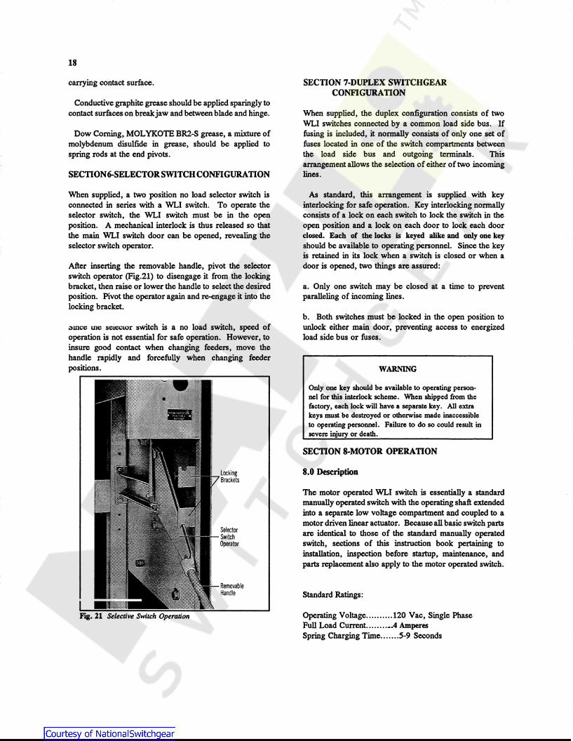
After inserting the removable handle, pivot the selector switch operator (Fig.21) to disengage it from the locking bracket, then raise or lower the handle to select the desired position. Pivot the operator again and re-engage it into the locking bracket.
;:,mce we 5e1ecLor 5witch is a no load switch, speed of operation is not essential for safe operation. However, to insure good contact when changing feeders, move the handle rapidly and forcefully when changing feeder positions.
Fig. 21 Selective Switch Operation
Locking Brackets
Selector Switch Operator
Removable Handle
SECTION 7-DUPLEX SWITCHGEAR CONFIGURATION
When supplied, the duplex configuration consists of two WLI switches connected by a common load side bus. If fusing is included, it normally consists of only one set of fuses located in one of the switch compartments between the load side bus and outgoing terminals. This arrangement allows the selection of either of two incoming lines.
As standard, this arrangement is supplied with key interlocking for safe operation. Key interlocking normally consists of a lock on each switch to lock the switch in the open position and a lock on each door to lock each door cl05ed. Each of the locks is keyed alike and only one key should be available to operating personnel. Since the key is retained in its lock when a switch is closed or when a door is opened, two things are assured:
a. Only one switch may be closed at a time to prevent paralleling of incoming lines.
b. Both switches must be locked in the open position to unlock either main door, preventing access to energized load side bus or fuses.
WARNING
Only one key should be available to operating penonnel for this interlock scheme. When shipped from the factory, each lock will have a separate key. All extra keys must be destroyed or otherwise made inaccessible to operating penonnel. Failure to do so could result in severe injury or death.
SECTION 8-MOTOR OPERATION
8.0 Description
The motor operated WLI switch is essentially a standard manually operated switch with the operating shaft extended into a separate low voltage compartment and coupled to a motor driven linear actuator. Because all basic switch parts are identical to those of the standard manually operated switch, sections of this instruction book pertaining to installation, inspection before startup, maintenance, and parts replacement also apply to the motor operated switch.
Standard Ratings:
Operating Voltage .......... 120 Vac, Single Phase Full Load Current ....... ·-·4 Amperes Spring Charging Time ...... .5-9 Seconds
8.1 Receiving and Startup
Motor operated units are shipped with the linear actuator decoupled from the shaft. Before the switch door can be opened, the switch must be manually opened as described in Section 3.0.0. The linear actuator may then be connected to the operating shaft. When control power is available, electrical operation can be used.
8.2 Electrical Operation
The linear actuator extends and retracts to operate the switch. Since the linear atuator drives the spring over· toggle mechanism, the switch blades move at a speed independent of the speed of the linear actuator.
For those configurations in which the motor is housed in an adjacent separate compartmen, the operating shaft is equipped with a button release decoupling pin located in the motor operator compartment. Removal of this pin allows the motor to be operated (for test purposes) without affecting WLI switch positions.
The linear actuator operates at 120 volts as standard and control power is normally supplied by the customer. For ll scncmlluc ..ii.a.gram and wiring diagram of the motor operator circuitry, refer to the job drawings.
8.3 Safety Interlocking
8.3.1 The standard scheme consists of a key interlock system, located in the motor operator compartment. The key interlock bolt, when extended, not only mechanically locks the WLI switch in the open position, but also breaks electrical motor contacts integral to the key interlock, and permits the key to be removed. With the key, the operator can then open the lock on the switch door. This scheme prevents closing the switch with the door open.
WARNING
Operating a WLI switch with a key interlock bolt extended will result in equipment damage and may also expose a person to bodily injury or death.
The key must be inserted into the interlock and rotated to retract the locking bolt before operating
8.4 Manual Operation (See Fig.22)
lt.11.J. Moa>r m ;:)eparate Compartment Adjacent to Switch
A steel clevis pin connects the linear actuator to the motor operated shaft. When this pin is removed, the linear
19
actuator is disconnected from the shaft and can be pivoted to the rear. The switch then can be manually operated with the removable handle provided. Never attempt to operate the linear actuator when it is disconnected from the shaft. Motor operated switches should be operated manually only when absolutely necessary. Since interlocking is sometimes accomplished thru the use of electrical contacts, disconnecting the motor may defeat the interlocking schemes.
WARNING
Defeating or disengaging safety interlocks on a WLI switch that is connected to a power source may result in property damage, bodily injury or death.
8.4.2 Motor in Same Compartment as Switch
A special pin connects the linear actuator to the switch operator. Loosen the screw holding the pin in place and remove this pin. Remove the bottom support pin holding the linear actuator, pull it out sufficiently to permit unplugging the linear actuator and removing it. The switch may now be manually operated with the removable handle.
8.5 Maintenance
The linear actuator itself is completely weathersealed. It and associated bearings are lubricated for their normal life many times in excess of the main switch and requires no maintenance.
SECTION 9-ELECTROMECHANICAL STORED ENERGY RELEASE (SHUNT TRIP)
9.0 Description
The stored energy release feature of the WLI load interrupter switch allows the operator to manually compress the main operating spring until it snaps over toggle. At this point, the stored energy lever system reacts to restrain further motion and latches the spring in its compressed state. The open or close operation can then be initiated by manual upward pressure on the trigger latch, with a finger or electrically by energizing the trigger coil (see Fig 23 for operating characteristics of trigger coils). When the latch is released, the stored energy in the main operating spring is released to rapidly rotate the main shaft to close or to open the switch. (See Fig.24)

20
CD - Steel Clevis Pin @-Hitch Pin
, __ 1'...11
I I -.. I I 'I I I I I I
I I I I
I I I I
I.
© - Motor Operator Hold Bracket © - Motor Operator Extended Shaft
Fig. 22 Manual Operation
9.1 Operation
WARNING
DO NOT DEVIATE FROM WARNING LABELS ON SWITCHGEAR
Failure to do so will result in equipment damage and may also expose a person to
bodily injury or death.
9.1.1 Charging the Spring
To initiate the closing action, the handle is inserted into the handle casting, and is rotated upward through an angle of 120 degrees. The handle casting presses against the spring lever (Fig.25) which then rotates with the handle casting. The spring rod is thus forced to compress the spring until the spring rod is snapped slightly over toggle. At this point the spring is now charged and the handle must be removed and returned to its storage location.
WLI Switch -Stored Energy Trio Coil Operating Data
Applied Inrush Coil Rating Voltage Current
101-449 195VAC RMS ---230 V Cap Trip 230VAC RMS ---
250VACRMS ---677C903G05 115VAC RMS 17.9ARMS 115VAC 125VAC RMS 18.7 ARMS
95VAC RMS 15.tARMS 101-418 220VACRMS 12.0ARMS 230VAC 250VAC RMS 13.4ARMS
190VACRMS 9.6ARMS 101-573 48VDC ---48VDC 60VDC ---
25VDC ---101-556 125VDC ---125VDC 140VDC ---
70VDC ---101-572 250VDC ---250VDC 280VDC ---
140VDC ---
Fig. 23 WU Switch - Stored Energy Trip Coil Operating Data

Fig. 24 Stored Energy Mechanism with Barriers and Mechanism
The spring rod stops with a clicking sound as the rear teeter bar roller seats against the lip of the trip link. It is held locked in this position by the resulting force vectors of the trip link assembly (see Fig.26). At the same time, the front roller of the teeter bar presses down on the trigger latch with sufficient pressure to resist trip forces. Consequently, the charged spring is held compressed by the mutually reacting forces of the spring restraint linkage, teeter bar, and trigger latch. The final result as shown in Fig. 26 is a charged spring restrained slightly over toggle by the spring restraint linkage. The switch, in this description, is open.
9.1.2 Closing the Switch
When the trigger latch is forced upward, either manually or by the action of the trigger coil, the front roller of the teeter bar drops over and down the lip of the trigger latch. The rear roller moves up and over the lip of the trip link. This releases the restraining linkages to the spring rod and allows the switch to rapidly close. The final result is a closed switch with the operating spring in an uncharged condition (Fig. 27).
Electrical Trigger Coil
Front ~~"""'oiRoller
Main Lever (On Shaft)
Fig. 25 Switch Open, Spring Not Oiarged
Electrical Trigger Coil
Teeter
·L! Main Lever (On Shaft) Spring Lever
Fig. 26 Switch Open, Spring Otarged
Trip Link
Spring
21

22
Trigger Coil
Fig. 27 Switch Closed, Spring Not Charged
Rear Roller
Trip Link.
9.1.3 Opening the Switch
Similar conditions prevail when initiating the opening action. The basic difference is that the handle and handle casting are rotated downward through an angle of 120 degrees. The spring lever and spring rod move upward until the spring rod snaps slightly over toggle and the spring is fully charged. The teeter bar rollers again reset and restrain the spring release linkage similar to that described in Section 9.1.1. (See Fig. 28.) The switch will remain charged until triggered to open by an upward movement of the trip latch, either manually or electrically.
9.2 Door Interlock (Shaft Blocking Cam)
WARNING
No attempt should be made to defeat this interlock while the switch is energized. Severe injury or death could result.
When the enclosure door is opened, a spring biased cam assembly located at the opposite end of the operating shaft from main spring moves into position preparatory to blocking inadvertent shaft rotation and consequent switch closing.
Trigger Coil
Teeter Rear Roller
Lever (On Shaft)
Fig. 28 Switch Closed, Spring Charged
The shaft rotation is inhibited by the blocking action between the blocking cam welded to the shaft, and the ramping cam of the spring biased assembly. If the door is open and a trip-to-close action is initiated, a jamming action takes place between the blocking cam and the ramping cam to stop shaft rotation; thus, the switch cannot close (see Fig.29).
The blocking action must be released by inserting the operational handle into the maintenance hub and slightly rotating to reset the charged main spring again over toggle.
9.3 Inspection and Maintenance
WARNING
The switch must be completely disconnected from all power sources before any inspection or maintenance procedures are attempted. Failure to do so could result in severe injury of death.
9.3.1 Blade and arc chute alignment procedures are the same for the standard WLI switch described in Section 5.

However, before the maintenance hub may be used, the following steps must be taken:
a. Remove the shaft lock assembly by removing its two 3/8" bolts.
b. Close the switch and leave spring in its discharged position. The maintenance hub may now be used for alignment procedures provided the trigger latch is raised during initial rotation of the operating shaft. Failure to release the trigger latch will damage components in the linkage assembly.
WARNING
Following alignment, be sure to replace the shaft lock assembly before energization. Failure to do so could result in severe injury or death.
Fig. 29 Operating Mechanism Showing Door Interlock, JfuxiUary Spring, Shaft Blocking Cam and Ramping Cam
9.3.2 Over Toggle Adjustment
There are two 1/2 inch diameter adjusting bolts on the front of the L-shaped bearing support bracket. This bracket is enclosed by the operating mechanism cover which must be removed before proceeding.
The bottom bolt adjustment affects the distance between the
23
teeter bar roller and the lip of the trip link (see Fig.25). Proper operation of the restraining linkage requires 3/64" to 5164" clearance between the rear teeter bar roller and the lip of the trip link. This adjustment is made with the switch closed and spring uncharged. Proper adjustment requires attention to the main blade alignment, over toggle alignment, and trip linkage alignment.
9.3.3 Open Gap Adjustment
The upper bolt adjustment affects the distance between the rear teeter bar roller and the lip of the trip link as shown in Fig. 27. This distance should be 3/64" to 5164" for proper operation of the restraining linkage. This adjustment is made with the switch open and spring uncharged. Proper adjustment requires attention to the main blade alignment, over toggle alignment, and trip linkage alignment.
Improper adjustment of the upper or lower bolts can result in the following:
a. The spring operating rod cannot be forced over toggle.
b. The restraining linkage can become inoperative resulting in the switch immediately closing or opening when the charged spring snaps over toggle.
SECTION 10-WVB SWITCHGEAR
DETAILED VCP-W BREAKER INFORMATION IS PROVIDED IN INSTRUCTION BOOK I.B. 32-255-1
10.0 Basic Description and Application
WVB switchgear is an integrated assembly of a visible disconnect switch, bus, fixed mounted vacuum circuit breaker, and control devices which are coordinated electrically and mechanically for high voltage circuit protection. WVB provides economic and reliable circuit interruption and fault protection for high voltage circuits 2.4 KV thru 27 KV. WVB is ideal for applications where load interrupter switches should not be applied, such as ground fault protection, high duty cycle applications, or high speed automatic transfers.
10.1 Identification
See section 1.1 of this booklet.
10.2 Safety Features
The seven safety features outlined on in Section 1.2 of this document also apply to WVB switchgear, in addition to the following features to reduce hazards and to provide proper operating sequences.

24
1. An external control switch is provided to allow customer to open or close the vacuum circuit breaker with full height main door closed. Optional key interlocking can also be provided to force circuit breaker to be opened prior to WLI switch being operated with full height main door closed.
2. Red and green indicating lights are provided to give visual indication of circuit breaker status (open/close positions).
3. Semi-flush fixed mounted relay and metering devices are mounted on the front hinged door in a protective relay cabinet for convenient access.
4. The breaker function indicators and controls are accessible and visible when full height door is opened. They are: breaker-open/close, closing spring-charged I discharged, close and trip buttons, operation counter breaker latch, and manual spring charging access.
5. The stored energy mechanism is vertically mounted on the front of the breaker for easy access. It is available for either DC or AC operation.
6. Vacuum interrupter contact wear indicator. Clearly visible, wear-gap (contact erosion) indicators require only an occasional check.
10.3 Receiving, Handling and Storage
The VCP-W breaker comes installed within the WVB assembly. See Section 2 of this document for WVB assembly.
10.4 Installation
Refer to Section 3 of this document for WVB assembly.
VCP-W Breaker before startup.
Refer to Section 4 (pg. 12) of I.B. 32-255-1 to perform following:
1. Perform Manual Operations Check.
2. Check Vacuum Interrupter Integrity.
3. Check breaker primary and secondary insulation.
4. Check Contact Erosion Indicator.
5. Check Primary Circuit Resistance.
6. Compare breaker nameplate information with switchgear drawings.
7. Perform electrical operations check.
Electromechanical/Solid State Relays/Devices - Before Startup.
WARNING
Electromechanical relays are mechanically "blocked• for shipment purposes. REMOVE ALL SHIPPING BLOCKS PRIOR TO SETTING OF RELAYS.
1. Set all protective relays in accordance with system protection coordination study data. All operation indicators on protective relays are factory set for the control voltage utilized.
2. Set or "program" all electronic devices in accordance with system protection coordination study data or other applicable data. Refer to those devices' instructions for procedures.
10.4 Operation
Refer to Section 4 of this document for mechanical safety interlocks for WVB assembly.
Standard Operating Procedure for WVB assembly
1. Trip the VCP-W breaker with full height door closed using the control switch mounted on the door, or trip the circuit breaker from the remote opearating station if so designed and connected to do so.
2. Open the WLI switch by opening the access door and manually opening switch. Since the switch is mechanically interlocked with the full height door, the door can not be opened without opening the WLI switch. (An optional feature may have VCP-W breaker and switch key interlocked to force VCP-W breaker to be opened prior to opening switch).
3. Full height door can now be opened.

Breaker Operation
Refer to Section 5 (pg. 21) of I.B. 32-255-1 for VCP-W breaker. Please note that WVB switchgear uses a VCP-W breaker as a "fixed" mounted device. The following sections under Section 5 do not apply to WVB switchgear.
1. Reference to draw-out information. 2. Interlocks, Sections 5.4 thru 5.4.4 3. Miscellaneous, Section 5.5 4. Levering Device, Section 5.6
10.S Maintenance
Refer to section 5 of this document for WVB assembly and WLI switch.
Breaker Maintenance
Refer to Section 6 (pg. 31) of I.B. 32-255-1 for VCP-W breaker. Please note that WVB switchgear uses a VCP-W breaker as a "fixed" mounted device. Any reference to araw-out construction such as "connected" position does not apply to WVB switchgear.
Breaker Removal
WARNING
Before accessing breaker the following steps must be taken Failure to do so could result in severe injury or death.
a. All upstream devices which could energize the breaker should be opened, padlocked, and tagged so that inadvertent closure cannot create a hazard.
b. The WLI switch should be opened by rotating the handle downward.
c. Before opening the door, look through a window to visually verify that all blades are disengaged from their stationary contacts. Use a flashlight if necessary.
d. After opening the door, a medium voltage sensing device should be used to determine if voltage is present.
e. If no voltage is present, a suitable grounding device
25
should be attached to the bus connections to discharge any static charge and assure that the bus connections remain at ground potential. Although the VCP-W breaker is a fixed mounted device in WVB switchgear it can be removed for maintenance purposes.
Removal Procedure
1. Remove the three (3) bolts on both the line and load side of each phase connection between VCP-W breaker and bus bar in rear of assembly. Total of eighteen (18) bolts. (See Fig. 30)
2. Remove front cover of VCP-W breaker.
3. Remove two (2) stationary mounting brackets located on lower left and right of VCP-W breaker. (See Fig. 31)
4. Remove two long screws on control plug on the bottom side of the circuit breaker and unplug.
5. Fasten optional lifting eye accessory, SIN 221C481G09, between the center top two screws on the circuit breaker mechanism cabinet that held on the front cover. Using a lifting device, lift up the front of the circuit breaker just enough to permit movement of breaker from side to side on its front wheels. Jockey the breaker out of the vertical section onto a temporary platform that is at the same elevation as the top of the bottom of the door frame.
F".g. 30 Rear view ofVCP-W breaker/WVB bus connection

26
Fig. 31 WVB Stationary Mounting Bracker
APPENDIX A
WLI Switchgear Bolt Tightness for Bus Connections
Use the following torque value for tightening bus joints. Use the widest standard flat washers that are consistent with bolt spacing.
Appendix A
Torque in Foot Pounds for Bolt Diameter
Diameter 1/4 5/16 3/8 1/2 5/8 Minimum Toraue 3.75 8 16.5 41.25 56.25 Nominal Torque 5 12 22 55 75
Maximum Torque 6.25 15 27.5 68.75 93.75

Amendment to IL 31-930C and IL31-931 for blade adjustment procedures. Revised: May 20, 2002
The following items are changed:
Section 5.3.2, paragraph b.
Check to see that the blades are closing fully. To do this, measure the distance from the front of the top of the break jaw to the outer edge of the main blade. This dimension should be between 0.125 "to .281". See figure below. Should adjustment be required, loosen the bolt holding the drive rod to the shaft and adjust the blade travel. Re-tighten the bolt to 23 foot pounds.
.125-.281
Section 5.3.6
r- 0 ,----~==--= \ \ L - - - +----'-----'
Break Jaw and Hinge Contact Bolts
The break jaw contact bolt and nuts provides the proper contact pressure between the main blades and the break jaw when the switch is closed (see Fig. 19). Before checking or adjusting the contact pressure, the switch must be in the closed position. In order to set this pressure, the locking nut at the break jaw end must be removed, the standard hex nut loosened, then tightened to 20 inch pounds for a 40kA asymmetrical fault-close rated switch or 25 inch-pounds for a 61 kA asymmetrical fault-close rated switch. Do not turn the bolt to set the tightness! Reinstall the locking nut and jamb it against the standard hex nut, being careful not to turn either the bolt or the hex standard nut.
For the hinge end, there are two configurations:
1. If there is only an elastic stop nut installed, tighten it to 25 ft-lb, and then back off the nut one full turn.
2. If there is an elastic stop nut that jambs a standard hex nut, remove the elastic stop nut, tighten the standard hex nut to 20 ft-lb, then back off one full turn. Reinstall the locking nut and jamb it against the standard hex nut, being careful not to turn either the bolt or the standard nut.
Standard ohmic readings between blade and break jaw should not exceed 60 micro-ohms.

I.L. 31-930 SUPPLEMENT 3A
SWGR. CONNECTION TD LIQUID FILLED TRANSFORMER
AS SHO\JN - LOW' VOLT AGE LEFT
OPP. HAND LOW' VOLT AGE RIGHT
PHASING C,B,A FRONT TD REAR
PHASING A,B,C FRONT TD REAR
"A"
I
L L ... - - -
__J "A"
VIEW FROM SIDE
FRONT OF SWITCHGEAR
TRANSFORMER H.V. BUSHING · I ~~~G
CABLE
SECTION "A-A"
VIEW FROM FRONT
D INST ALL TRANSFORMER FLANGE TD S\./ITCHGEAR PER SECTION 3.2 OF IL 31-930-C
2) INST ALL CABLE LUG ADAPTOR \./ITH LUG TO TRANSFORMER BUSHING USING 1/2 1 BDL TS, \./ ASHERS AND NUTS SUPPLIED. CFDR S\./GR \./ITH T\./D CABLES PER PHASE, LUGS \./ILL BE INST AL LED BACK-TO-BACK ON ADAPTOR.)
3) CUT CABLES TD REACH LUG ON TRANSFORMER BUSHING FOR EACH PHASE.
4) STRIP APPROX IMA TEL Y 1 H TD 1.5 .. OF IN SULA TIDN FROM END OF CABLES AND SLIP INTO LUGS.
5) CLAMP DR CRIMP DO\./N LUGS ONTO BARE CABLE CONDUCTORS.
IL319.30_3A

I.L. 31-930 SUPPLEMENT 3B
SWGR. CONNECTION TD OUTDOOR DRY TYPE TRANSFORMER
AS SHOWN - LO\J VOLT AGE LEFT PHASING AJBJC FRONT TO REAR
OPP. HAND LO\J VOLT AGE RIGHT PHASING AJBJC FRONT TO REAR
TRANSFORMER H.V. TERMINATIONS
0 GROUND BUS
~
VIEW FROM SIDE
FRONT OF' SWITCHGEAR
FLANGE
SECTION "A-A"
VIEW FROM FRONT
D INST ALL TRANSFORMER TO S\./ITCHGEAR FLANGE. <MAKE SURE GASKET IS INSTALLED BET\./EEN FLANGE AND TRANSFORMER>
2> FIND BOX \./ITH CABLC LUGS, CABLE SPREADERS, ETC SUPPLIED \./ITH S\./GR.
3) INSTALL CABLE LUG ADAPTOR \./ITH LUG TO TRANSFORMER TERMINAL USING 112* BOLTS, \./ASHERS AND NUTS SUPPLIED. \./HEN ADAPTOR IS NOT SUPPLIED, INSTALL LUG TD TRANSFORMER. TERMINAL USING BOLTS, \./ASHERS AND NUTS SUPPLIED SIZED FOR HOLE IN LUG PAD.
FOR S\./GR \./ITH T\./O CABLES PER PHASC THE LUGS ARE FACTORY INSTALLED BACK-TD-BACK ON ADAPTOR. \./HEN ADAPTOR IS NOT SUPPLIED, LUGS TO BE . FIELD INSTALLED BACK-TO-BACK ON TRANSFORMER TERMINAL.
4) COIL OF CABLE MUST BE CUT TO LENGTH TD REACH FROM LUG ON FUSE TERMINAL TO LUG ON TRANSFORMER TERMINAL FDR EACH PHASE.
5) AFTER CABLES ARE CUT, STRIP APPROX IMA TEL Y l * TO 1.5* OF INSULATION FROM BOTH ENDS.
6) SLIP ONE END OF CABLE INTO LUG ON FUSE TERMINAL AND CLAMP OR CRIMP DO\./N LUGS ONTO BARE CABLE CONDUCTOR. DD THIS FDR EACH PHASE.
7) RUN CABLES THROUGH CABLE SPREADER<S> IN S\./ITCH SECTION, THROUGH SUPPORT IN S\./GR SIDE SHEET AND THROUGH CABLE SPREADER<S> IN TRANSFORMER SECTION. POSITION CABLE SPREADEDS SD THAT THEY ARE APPROXIMATELY HALF \./AY BET\./EEN LUGS AND SUPPORT IN S\./GR SIDE SHEET. USE NYLON TIES TD FASTEN SPREADERS TD CABLE. <NOTE: FDR ONE CABLE PER PHASE THERE IS ONE SPREADER AND FOR T\./O CABLES PER PHASE THERE ARE T\./O SPREADERS IN S\./GR AND IN TRANSFORMER SECTIONS.>
· 8) SLIP END OF CABLE INTO LUG ON TRANSFORMER TERMINAL AND CLAMP DR CRIMP DD\./N LUGS ONTO BARE CABLE CONDUCTOR. DD THIS FDR EA-CH PHASE.
9) CONNECT S\./GR GROUND BUS TD TRANSFORMER GROUND PAD.
IL31930_38
I.L. 31-930 SUPPLEMENT 3C
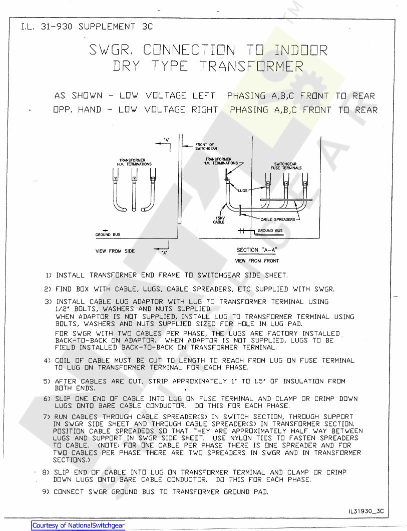
SWGR, CONNECTION TD INDOOR DRY TYPE TRANSFORMER
AS SHOWN - LOW' VOLTAGE LEFT
OPP. HAND - LOW' VOLTAGE RIGHT
PHASING A,B,C FRONT TD REAR
PHASING A,B,C FRONT TO REAR
.....
TRANSFORMER H.V. TERMINATIONS
GROUND SUS
VIEW FROM SIDE
FRONT or SWITCHGEAR
SECTION "A-A"
VIEW FROM FRONT
D INST ALL TRANSFORMER END FRAME TD S\./ITCHGEAR SIDE SHEET.
2) FIND BOX \./ITH CABLE, LUGS, CABLE SPREADERS, ETC SUPPLIED \./ITH S\./GR.
3) INSTALL CABLE LUG ADAPTOR \./ITH LUG TD TRANSFORMER TERMINAL USING 1/2 .. BDL TS, \./ASHERS AND NUTS SUPPLIED. \./HEN ADAPTOR IS NOT SUPPLIED, INSTALL LUG TD TRANSFORMER TERMINAL USING BDL TS, \./ASHERS AND NUTS SUPPLIED SIZED FDR HOLE IN LUG PAD.
FDR S\v'GR \./ITH T\v'D CABLES PER PHASE, THE LUGS ARE FACTORY INSTALLED . BACK-TO-BACK ON ADAPTOR. \./HEN ADAPTOR IS NOT SUPPLIED, LUGS TO BE FIELD INSTALLED BACK-TD-BACK ON TRANSFORMER TERMINAL.
4) COIL OF CABLE MUST BE CUT TD LENGTH TD REACH FROM LUG ON FUSE TERMINAL TD LUG ON TRANSFORMER TERMINAL FDR EACH PHASE.
5) AFJER CABLES ARE CUT, STRIP APPROXIMATELY lH TO 1.5 .. OF INSULATION FROM BOTH ENDS.
6) SLIP ONE END OF CABLE INTO LUG ON FUSE TERMINAL AND CLAMP DR CRIMP DO\v'N LUGS ONTO BARE CABLE CONDUCTOR. DD THIS FDR EACH PHASE.
7) RUN CABLES THROUGH CABLE SPREADER<S) IN S\v'ITCH SECTION, THROUGH SUPPORT IN S\v'GR SIDE SHEET AND THROUGH CABLE SPREADER<S) IN TRANSFORMER SECTION. POSITION CABLE SPREADEDS SO THAT THEY ARE APPROXIMATELY HALF \v'AY BET\v'EEN LUGS AND SUPPORT" IN S\v'GR SIDE SHEET. USE NYLON TIES TO FASTEN SPREADERS TO CABLE. <NOTE: FOR ONE CABLE PER PHASE THERE IS ONE SPREADER AND FOR T\./O CABLES PER PHASE THERE ARE T\./O SPREADERS IN S\./GR AND IN TRANSFORMER SECTIONS.)
8) SLIP END OF CABLE INTO LUG ON TRANSFORMER TERMINAL AND CLAMP OR CRIMP DO\./N LUGS ONTO BARE CABLE CONDUCTOR. DO THIS FOR EACH PHASE.
9) CONNECT S\v'GR GROUND BUS TD TRANSFORMER GROUND PAD.
IL31930_3C
I.L. 31-930-C Supplement 1, August, 1997
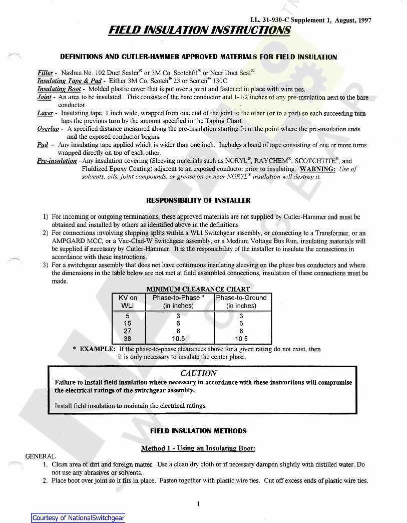
FIELD INSIJLA TION INSTRIJCTIONS
DEFINITIONS AND CUTLER-HAMMER APPROVED MATERIALS FOR FIELD INSULATION
Filler - Nashua No. 102 Duct Sealer® or 3M Co. ScotchfiI® or Neer Duct Seal®. "J,;;;dating Tape & Pad - Either 3M Co. Scotch® 23 or Scotch® 130C. Insulating Boot - Molded plastic cover that is put over a joint and fastened in place with wire ties. Joint - An area to be insulated. This consists of the bare conductor and 1-1 /2 inches of any pre-insulation next to the bare
conductor. Layer - Insulating tape, 1 inch wide, wrapped from one end of the joint to the other (or to a pad) so each succeeding tum
laps the previous tum by the amount specified in the Taping Chart. Overlap - A specified distance measured along the pre-insulation starting from the point where the pre-insulation ends
and the exposed conductor begins. Pad - Any insulating tape applied which.is wider than one inch. Includ~s a band of tape consisting of one or more turns
wrapped directly on top of each other. Pre-insulation -Any insulation covering (Sleeving materials such as NORYL ®,RAYCHEM®, SCOTCHTITE®, and
Fluidized Epoxy Coating) adjacent to an exposed conductor prior to insulating. WARNING: Use of solvents, oils, joint compounds, or grease on or near NORYL® insulation ·will destroy it.
RESPONSIBILITY OF INSTALLER
1) For incoming or outgoing terminations, these approved materials are not supplied by Cutler-Hammer and must be obtained and installed by others as identified above in the definitions.
2) For connections involving shipping splits within a WLI Switchgear assembly, or connecting to a Transformer, or an Afv1PGARD MCC, or a Vac-Clad-W Switchgear assembly, or a Medium Voltage Bus Run, insulating materials will be supplied if necessary by Cutler-Hammer. It is the responsibility of the installer to insulate the connections in accordance with these instructions.
· 3) For a switchgear assembly that does not have continuous insulating sleeving on the phase bus conductors and where the dimensions in the table below are not met at field assembled connections, insulation of these connections must be made.
MINIMUM CLEARANCE CHART KV on Phase-to-Phase * Phase-to-Ground WLI (in inches) (in inches)
5 3 3 15 6 6 27 8 8 38 10.5 10.5
* EXAMPLE: If the phase-to-phase clearances above for a given rating do not exist, then it is only necessary to insulate the center phase.
CAUTION Failure to install field insulation where necessary in accordance with these instructions will compromise the electrical ratings of the switchgear assembly.
Install field insulation to maintain the electrical ratings.
FIELD INSULATION METHODS
Method 1 - Using an Insulating Boot: GENERAL
1. Clean area of dirt and foreign matter. Use a clean dry cloth or if necessary dampen slightly with distilled water. Do not use any abrasives or solvents.
2. Place boot over joint so it fits in place. Fasten together with plastic wire ties. Cut off excess ends of plastic wire ties.
1
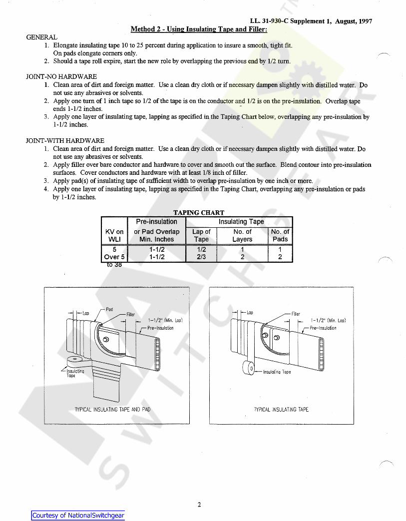
I.L. 31-930-C Supplement 1, August, 1997 Method 2 - Using Insulating Tape and Filler:
GENERAL 1. Elongate insulating tape 10 to 25 percent during application to insure a smooth, tight fit.
On pads elongate corners only. 2. Should a tape roll expire, start the new role by overlapping the previous end by 1/2 turn.
JOINT-NO HARDWARE 1. Clean area of dirt and foreign matter. Use a clean dry cloth or if necessary dampen slightly with distilled water. Do
not use any abrasives or solvents. 2. Apply one turn of 1 inch tape so 112 of the tape is on the conductor and 112 is on the pre-insulation. Overlap tape
ends 1-1/2 inches. -3. Apply one layer of insulating tape, lapping as specified in the Taping Chart below, overlapping any pre-insulation by
1-1/2 inches.
JOINT-WITH HARDWARE 1. Clean area of dirt and foreign matter. Use a clean dry cloth or if necessary dampen slightly with distilled water. Do
not use any abrasives or solvents. 2. Apply filler over bare conductor and hardware to cover and smooth out the surface. Blend contour into pre-insulation
surfaces. Cover conductors and hardware with at least 1/8 inch of filler. 3. Apply pad(s) of insulating tape of sufficient width to overlap pre-insulation by one inch or more. 4. Apply one layer of insulating tape, lapping as specified in the Taping Chart, overlapping any pre-insulation or pads
by 1-112 inches.
TAPING CHART Pre-insulation Insulating Tape
KV on or Pad Overlap Lap of No. of No. of WLI Min. Inches Tape Layers Pads
5 1-1/2 1/2 1 1 Overs 1-1/2 2/3 2 2 lO ~o
1-1/2" (Min. Lap) 1-1 /2" (Min. Lap)
1YPICAL INSULATING TAPE AND PAD TYPICAL INSULATING TAPE
2