image formation - kth · image formation is a physical process that captures scene illumination ......
TRANSCRIPT

DD2423 Image Analysis and Computer Vision
IMAGE FORMATIONMarten Bjorkman
Computational Vision and Active PerceptionSchool of Computer Science and Communication
October 24, 2012
1

Image formation
Goal: Model the image formation process
• Radiometry and photometry
• Perspective projection
– properties– approximations
• Coordinate systems
• Homogeneous coordinates
• Sampling
• Warping
2

Image formation
Image formation is a physical process that captures scene illuminationthrough a lens system and relates the measured energy to a signal.
3

Radiometry and Photometry
Radiometry: science of measuring light in any portion of the electromagneticspectrum. In practice, usually limited to the measurement of infrared, visibleand ultraviolet light using optical instruments.
Photometry: science of measuring visible light detectable by the human eye,restricted to wavelengths from about 360 to 830 nm. We see light of differentwavelengths as a continuum of colors ranging through the visible spectrum:650 nm is red, 540 nm is green, 450 nm is blue, and so on.
Photometry is just like radiometry except that everything is weighted by thespectral response of the eye.
4
Basic concepts
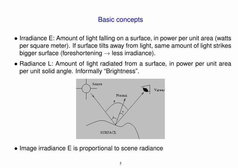
• Irradiance E: Amount of light falling on a surface, in power per unit area (wattsper square meter). If surface tilts away from light, same amount of light strikesbigger surface (foreshortening→ less irradiance).
• Radiance L: Amount of light radiated from a surface, in power per unit areaper unit solid angle. Informally “Brightness”.
• Image irradiance E is proportional to scene radiance
5

Light source examples
Left: Forest image (left): sun behind observer, (right): sun opposite observerRight: Field with rough surface (left): sun behind observer, (right): sun opposite observer.
6

Digital imaging
Image irradiance E × area × exposure time→ Intensity
• Sensors read the light intensity that may be filtered through color filters, anddigital memory devices store the digital image information either as RGB colorspace or as raw data.
• An image is discretized: sampled on a discrete 2D grid→ array of color values.
7

Steps in a typical image processing system
• Image acquisition: capturing visual data by a vision sensor
• Discretization/digitalization - Quantization - Compression: Convert data intodiscrete form; compress for efficient storage/transmission
• Image enhancement: Improving image quality (low contrast, blur noise)
• Image segmentation: Partition image into objects or constituent parts.
• Feature detection: Extracting pertinent features from an image that areimportant for differentiating one class of objects from another.
• Image representation: Assigning labels to an object based on informationprovided by descriptors.
• Image interpretation: Assigning meaning to image information.
8

Parameters of Digital Imaging
• Optical Parameters of lens system
- lens type, focal length, field of view, aperture (lens opening)
• Photometric/Radiometric Properties:
- light type, intensity, illumination
- reflectance properties of the viewed surfaces
• Geometric/Extrinsic Parameters
- type of projections
- position and orientation of the camera in space
• Intrinsic Parameters
- physical properties of the photosensitive matrix
- perspective distortions introduced by the imaging process
9

Imaging geometry - From world point to pixel
• World points are projected onto a camera sensor chip.
• Camera sensors sample the irradiance to compute energy values.
• Positions in camera coordinates (in mm) are converted to image coordinates(in pixels) based on the intrinsic parameters of the camera:
- size of each sensor element,
- aspect ratio of the sensor (xsize/ysize),
- number of sensor elements in total,
- image center of sensor chip relative to the lens system.
10

Pinhole camera or “Camera Obscura”
11

Pinhole camera and perspective projection
• A mapping from a three dimensionsal (3D) world onto a two dimensional (2D)plane in the previous example is called perspective projection.
• A pinhole camera is the simplest imaging device which captures the geometryof perspective projection.
• Rays of light enter the camera through an infinitesimally small aperture.
• The intersection of light rays with the image plane form the image of the object.
12

Perspective projection
13

Pinhole camera - Perspective geometry
X
Y
image coordinates
image plan
e
centeroptical
p=(x,y,f) P=(X,Y,Z)world coordinates
optical axisZ
focal length
• The image plane is usually modeled in front of the optical center.
• The coordinate systems in the world and in the image domain areparallel. The optical axis is ⊥ image plane.
14

Imaging geometry - Basic camera models
• Perspective projection (general camera model)
All visual rays converge to a common point - the focal point
• Orthographic projection (approximation: distant objects, center of view)
All visual rays are perpendicular to the image plane
Image
Orthographic projection
Image
Perspective projection
focal
point
15

Perspective projection
16

Projection equations
yY
Z
f
• Perspective mappingxf=
XZ,
yf=
YZ
• Orthographic projectionx = X , y = Y
• Scaled orthography - Z0 constant (representative depth)
xf=
XZ0
,yf=
YZ0
17

Perspective transformation
• A perspective transformation has three components:
- Rotation - from world to camera coordinate system
- Translation - from world to camera coordinate system
- Perspective projection - from camera to image coordinates
• Basic properties which are preserved:
- lines project to lines,
- collinear features remain collinear,
- tangencies,
- intersections.
18

Perspective transformation (cont)
cameracentre
parallellines
pointvanishing
image
e
Each set of parallel lines meet at a different vanishing point - vanishing point as-sociated to this direction. Sets of parallel lines on the same plane lead to collinearvanishing points - the line is called the horizon for that plane.
19

Architectural design for dummies
20

Homogeneous coordinates
• Model points (X ,Y,Z) in R 3 world by (kX ,kY,kZ,k) where k is arbitrary 6= 0,and points (x,y) in R 2 image domain by (cx,cy,c) where c is arbitrary 6= 0.
• Equivalence relation: (k1X ,k1Y,k1Z,k1) is same as (k2X ,k2Y,k2Z,k2).
• Homogeneous coordinates imply that we regard all points on a ray (cx,cy,c) asequivalent (if we only know the image projection, we do not know the depth).
• Possible to represent “points in infinity” with homogreneous coordinates(X ,Y,Z,0) - intersections of parallel lines.
21

Computing vanishing points
22
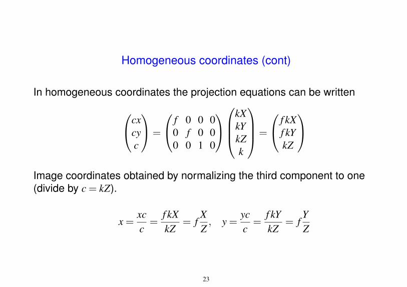
Homogeneous coordinates (cont)
In homogeneous coordinates the projection equations can be writtencxcyc
=
f 0 0 00 f 0 00 0 1 0
kXkYkZk
=
f kXf kYkZ
Image coordinates obtained by normalizing the third component to one(divide by c = kZ).
x =xcc=
f kXkZ
= fXZ, y =
ycc=
f kYkZ
= fYZ
23

Transformations in homogeneous coordinates
• Translation XYZ
→X
YZ
+
∆X∆Y∆Z
XYZ1
→
1 0 0 ∆X0 1 0 ∆Y0 0 1 ∆Z0 0 0 1
XYZ1
• Scaling
XYZ1
→
SX 0 0 00 SY 0 00 0 SZ 00 0 0 1
XYZ1
24

Transformations in homogeneous coordinates II
• Rotation around the Z axisXYZ1
→
cosθ −sinθ 0 0sinθ cosθ 0 0
0 0 1 00 0 0 1
XYZ1
• Mirroring in the XY plane
XYZ1
→
1 0 0 00 1 0 00 0 −1 00 0 0 1
XYZ1
25

Transformations in homogeneous coordinates III
Common case: Rigid body transformations (Euclidean) X ′
Y ′
Z′
→ R
XYZ
+
∆X∆Y∆Z
where R is a rotation matrix (R−1 = RT ) is written
X ′
Y ′
Z′
1
=
∆X
R ∆Y∆Z
0 0 0 1
XYZ1
26

Perspective projection - Extrinsic parameters
Consider world coordinates (X ′,Y ′,Z′,1) expressed in a coordinate systemnot aligned with the camera coordinate system
XYZ1
=
∆X
R ∆Y∆Z
0 0 0 1
X ′
Y ′
Z′
1
= A
X ′
Y ′
Z′
1
Perspective projection
c
xy1
=
f 0 0 00 f 0 00 0 1 0
XYZ1
= PA
X ′
Y ′
Z′
1
= M
X ′
Y ′
Z′
1
27

Intrinsic camera parameters
Due to imperfect placement of the camera chip relative to the lens system,there is always a small relative rotation and shift of center position.
28

Intrinsic camera parameters
A more general projection matrix allows:
• Image coordinates with an offset origin
• Non-square pixels
• Skewed coordinate axes
• Five variables below are known as the camera’s intrinsic parameters
K =
fu γ u00 fv v00 0 1
, P =(
K 0)=
fu γ u0 00 fv v0 00 0 1 0
Most important is the focal length ( fu, fv). Normally, fu and fv are assumedequal and the parameters γ, uo and vo close to zero.
29

Example: Perspective mapping
30

Example: Perspective mapping in stereo
31

Mosaicing
32

Exercise
Assume you have a point at (3m,2m,8m) with respect to the cameras coordinatesystem. What is the image coordinates, if the image has a size (w,h) = (640,480)and origin in the upper-left corner, and the focal length is f = 480?
33

Exercise
Assume you have a point at (3m,−2m,8m) with respect to the cameras coordinatesystem. What is the image coordinates, if the image has a size (w,h) = (640,480)and origin in the upper-left corner, and the focal length is f = 480?
Answer:x = f
XZ+
w2= (480∗3/8+640/2) = 500
y = fYZ+
h2= (−480∗2/8+480/2) = 120
34

Approximation: affine camera
35

Approximation: affine camera
• A linear approximation of perspective projectionxy1
=
m11 m12 m13 m14m21 m22 m23 m240 0 0 1
XYZ1
• Basic properties
– linear transformation (no need to divide at the end)– parallel lines in 3D mapped to parallel lines in 2D
Angles are not preserved!
36
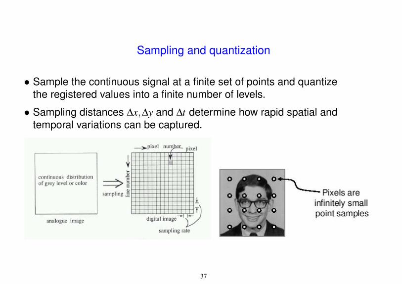
Sampling and quantization
• Sample the continuous signal at a finite set of points and quantizethe registered values into a finite number of levels.
• Sampling distances ∆x,∆y and ∆t determine how rapid spatial andtemporal variations can be captured.
37

Sampling and quantization
• Sampling due to limited spatial and temporal resolution.
• Quantization due to limited intensity resolution.
38

Quantization
• Quantization: Assigning, usually integer, values to pixels (sampling anamplitude of a function).
• Quantization error: Difference between the real value and assigned one.
• Saturation: When the physical value moves outside the allocated range,then it is represented by the end of range value.
39

Resolutions from 1024x1024 to 32x32
40

Changes in image resolution
41

Typical numbers
• # bits/pixel: 8 = 23
• # grey-levels: 256 = 28
• # pixels/image: 10242 = 220
• # bits/image: 223 = 8×10⁶
• # possible images: (28)220 (kind of many)
256×256 image points→ 65 kb
512×512 image points→ 262 kb
1024×1024 image points→ 1 Mb
42
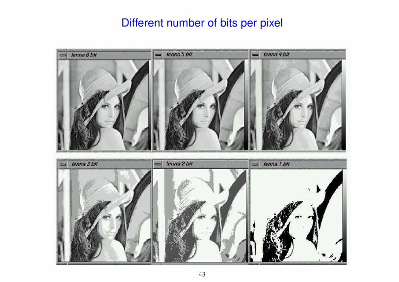
Different number of bits per pixel
43

Image warping
Resample image, model as coordinate transformation: u = u(x,y), v = v(x,y).
44

Image warping
45

Image warping - Approach 1
For each point in (x,y) domain compute new (u,v) value.
Assign nearest (ud,vd) to values f (x,y).
Empty holes, quantization effects
Image warping - Approach 2
For each grid point in (u,v) domain compute corresponding (x,y) values.
Perform interpolation in cell defined by ([x] , [y]) and ([x+1] , [y+1]).
Blurred details
46
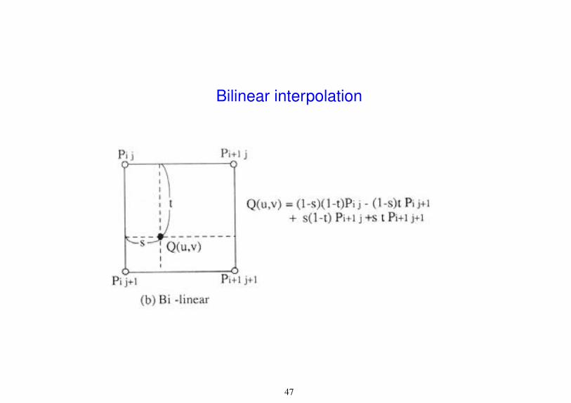
Bilinear interpolation
47

Nearest Neighbor vs. Bilinear Interpolation
48

Summary of good questions
• What parameters affects the quality in the acquisition process?
• What is a pinhole camera model?
• What is the difference between intrinsic and extrinsic camera parameters?
• How does a 3D point get projected to a pixel with a perspective projection?
• What are homogeneous coordinates and what are they good for?
• What is a vanishing point and how do you find it?
• What is an affine camera model?
• What is sampling and quantization?
49

Readings
• Gonzalez and Woods: Chapter 2
• Cipolla and Gee’s notes on projection (see web page)
50