image formation through monoaxial plane-parallel plates
TRANSCRIPT
Image formation through monoaxial plane-parallel plates
Maria C. Simon
A quantitative study of the formation of images through plane-parallel plates of a monoaxial birefringentmaterial has been performed. Formulas for the transverse and longitudinal displacements of the image havebeen obtained, and it is shown that a first-order astigmatism appears which is due exclusively to theanisotropy of the crystal. An exact calculation by ray tracing proves that the approximate formulas aresatisfactory.
1. Introduction
With the aim of studying the formation of imagesthrough polarizing elements made of birefringent ma-terials we have developed ray tracing formulas. Thesehave been published in the papers "Ray Tracing For-mulas for Monoaxial Optical Components"' and "RayTracing Formulas for Monoaxial Optical Components:Vectorial Formulation."2 Subsequently we have ap-plied these formulas to the design and optimization ofa Wollaston prism.3 In this analysis we showed thatthe aberrations originated by the anisotropic proper-ties of the material and the geometric form of theelements which make up the Wollaston are extremelyimportant. As in the Wollaston prism the anisotropyof the material is combined with the anisotropy of thewedges, the effects due exclusively to the birefringentmaterial may not be distinguished clearly. To appre-ciate these effects, in this work we study the formationof images through plane-parallel monoaxial plates,since in this case there is no anisotropy due to thegeometric shape of the plate. If we also consider theprincipal ray of the incident beam perpendicular to theplate, there will be no anisotropic effect other than theanisotropy due to the birefringent material of the plateitself.
In the previous works",2 we showed that the refrac-tion of light in birefringent crystals may be calculatedin two steps. First the normal to the refracted wave-front is calculated by Snell's law with a refractive indexwhich varies with the direction of the incident wave.Once the unit vector normal to the refracted wavefront
The author is with University of Buenos Aires, Physics Depart-ment, Optics Laboratory, 1428 Buenos Aires, Argentina.
Received 5 June 1987.0003-6935/881204176-07$02.00/0.© 1988 Optical Society of America.
is obtained, the direction of the ray is calculated add-ing to this unit vector a vector parallel to the opticalaxis.
We show how the variation of the index and thedisplacement of the ray affect the formation of imagesthrough monoaxial plane-parallel plates when a con-vergent beam incides normal to the plate. We carryout the calculations separating first-order effects fromthose of higher orders and develop approximate for-mulas to first order for the displacement of the conver-gence point of the beam, first-order astigmatism, andthe transverse displacement of the image. This analy-sis will be performed for the case in which the opticalaxis is parallel to the discontinuity surface, and ingeneral for an angle between the optical axis and thediscontinuity surface.
Following the steps considered above we first con-fine our study to the influence of the variation of theindex; we see that it is always of higher order. Second,we analyze the displacement of the ray which gives thefirst-order effects, which are astigmatism and thetransverse displacement of the extraordinary image.
An exact calculation by ray tracing will serve tocheck the approximate formulas.
II. Influence of the Variation of the Refractive Index onthe Focus
It is well known that, when a convergent beamincides normal to a plane-parallel plate of isotropicmaterial of index n2 and width d, the convergencepoint of the beam is displaced by
Ax= x-xo =d 1 n,(1n2)
where n is the index of the surrounding medium, x0 isthe convergence point of the beam when the plate isremoved, and x is the convergence point when thebeam passes through the plate. This formula is validto first order, and the corresponding geometric con-struction may be seen in Fig. 1.
4176 APPLIED OPTICS / Vol. 27, No. 20 / 15 October 1988

d
In2 P_4
I \
ni
y
VTV
nit
1.56j
-Y
/ P /1:Il
Fig. 1. Ray tracing for an isotropic plane-parallel plate.
When the plate is of monoaxial birefringent material(with indices n0 and ne) the ordinary rays are refractedfollowing the same path as in an isotropic material ofindex equal to the ordinary index (n). For this reasonthe displacement of the convergence point will be cal-culated with Eq. (1), setting n2 = n. On the otherhand the calculations of the index and the ray in theextraordinary case will have to be performed as ex-plained previously. The variation of index of refrac-tion may be calculated by means of the formulas ob-tained in earlier works., 2 The vector form is
w4A -w
2B + C = 0,
A = (1 + b - (S* j)2 - [S. ( X -)]21)2
B = 2(1 + bl - (S )2 -[S (nX z3)]2})
-4b ( [1 - (S *n)2][1 - ( )2]
-SnX -)]2,
C [b(3 * )2 + ( U) ]
[see Eqs. (12) and (19)-(21) in Ref. 2], where
2 2
=2- .2 no ( )'
Ue flnU = -
2 2e
(2)
Y=O
/ 0=45'
Y~~~90°90
1.54
1.52
1.50-
-go -60° -30' 0' 30 60' go.
Fig. 2. Refractive index vs incident angle for t9 = O.
n is the unit vector perpendicular to the discontinuitysurface (in our case n = x), Z3 is the unit vector in thedirection of the optical axis, and S is the unit vector inthe direction of the incident ray. For the calculationsthat follow we shall use the coordinate system indicat-ed in Figs. 1, 5, and 6. The (yz) plane is the disconti-nuity plane, and the optical axis lies in the (x,z) plane.
A. Optical Axis Parallel to the Discontinuity Surface
In this case,
Z3 - n = 0. (9)
If a is the angle between the incident ray and thenormal to the surface, and y is the angle between theincident plane and the (x,z) plane, we obtain
(S n) = cosa,
S (n X 3) = sina siny.
(10)
(11)
Substituting Eqs. (9), (10), and (11) into Eqs. (3), (4),and (5) and solving the biquadratic Eq. (2), the follow-ing expression for n"/n, is obtained:
- '1 i 12 sin 2a cos2 (12)
(3) Figure 2 shows the curves for n' as a function of a forn = 1 and several values of y. It is easy to see thatn = ne when the incident plane is perpendicular to the(x,z) plane which contains the optical axis (i.e., y =r/2), and when the incident plane coincides with the(x,z) plane (y = 0), the expression for n"/n is
(13)nl ne yj ( 2 2a
(4) In Fig. 2 it may be observed that around a = 0 thevariation of the index is.of second order, and that for
(5) a = the index is
(14)
For this reason the variation of the index only affects(6) the higher-order terms corresponding to aberrations,
and to first order all the calculations may be performedwith a constant index equal to ne-
B. Optical Axis Parallel to the Incident Plane
(8) When the optical axis forms an angle with thediscontinuity surface (i.e., with the z axis), we analyze
15 October 1988 / Vol. 27, No. 20 / APPLIED OPTICS 4177
- w f
b
l l l
II
nI
n = n.
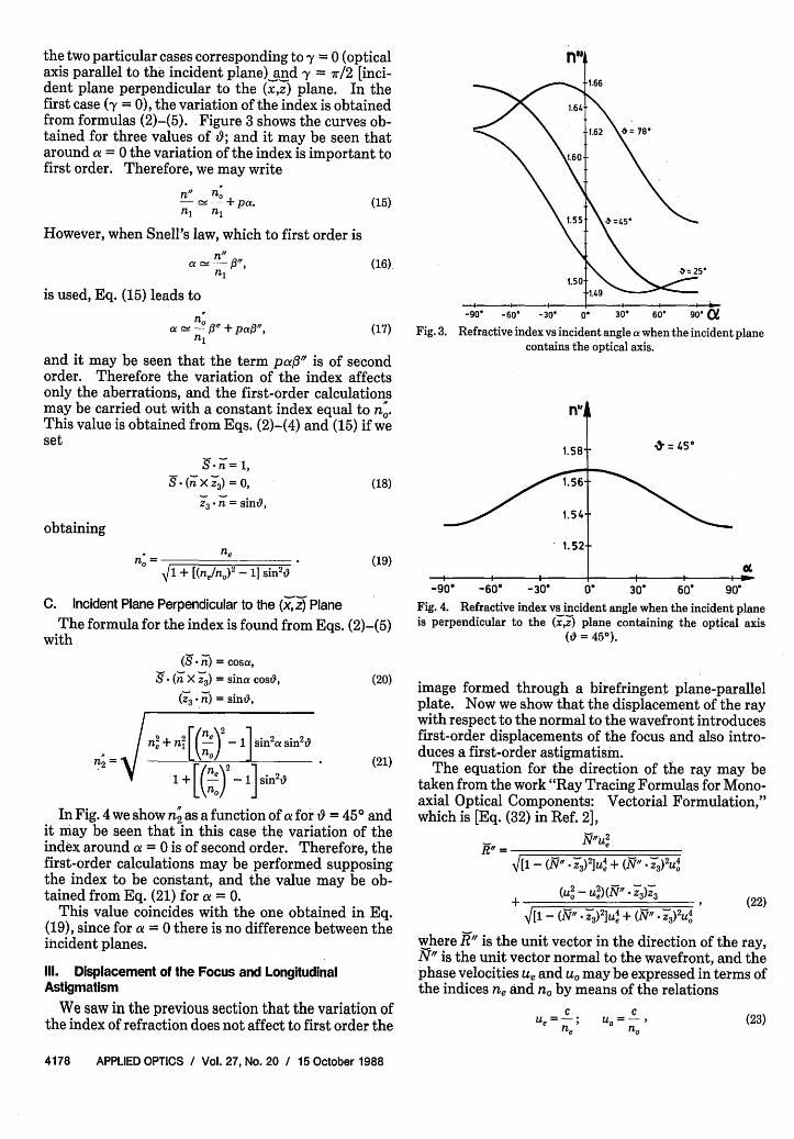
the two particular cases corresponding to y = 0 (opticalaxis parallel to the incident plane) and y = 7r/2 [inci-dent plane perpendicular to the (x,z) plane. In thefirst case (y = 0), the variation of the index is obtainedfrom formulas (2)-(5). Figure 3 shows the curves ob-tained for three values of 0; and it may be seen thataround a = 0 the variation of the index is important tofirst order. Therefore, we may write
n" nO a- - + a.
n1 nj
However, when Snell's law, which to first order is
nfl
is used, Eq. (15) leads to
a - 3" + pao",
(15)
(16)
(17)
and it may be seen that the term paf3" is of secondorder. Therefore the variation of the index affectsonly the aberrations, and the first-order calculationsmay be carried out with a constant index equal to no.This value is obtained from Eqs. (2)-(4) and (15) if weset
n= 1,
(18)-(WXz 3 3) = n,Z3 W = sinO,
obtaining
no =
78'
-90' -60, -30' 0. 30' 60' 90'
Fig. 3. Refractive index vs incident angle a when the incident planecontains the optical axis.
flu4
1.58t
1.56
1.54
1.52(19)
V1 + [(ne/no)2- 1] sin2
C. Incident Plane Perpendicular to the (x,z) Plane
The formula for the index is found from Eqs. (2)-(5)with
-90. -60' - 30
. = 45'
0- 30- 60' 90
Fig. 4. Refractive index vs incident angle when the incident planeis perpendicular to the (x),z plane containing the optical axis
(O = 450).
( - W) = cosa,
( X Y) = sina coso,
(_Z * ) = sin6,
n= n + n(f 2_ 1 in2a Sin2 o
r/ne\2
1 + n,- _ 1J sin 2t
(20)
(21)
In Fig. 4 we show n2 as a function of a for t = 450 andit may be seen that in this case the variation of theindex around a = 0 is of second order. Therefore, thefirst-order calculations may be performed supposingthe index to be constant, and the value may be ob-tained from Eq. (21) for a = 0.
This value coincides with the one obtained in Eq.(19), since for a = 0 there is no difference between theincident planes.
Ill. Displacement of the Focus and LongitudinalAstigmatism
We saw in the previous section that the variation ofthe index of refraction does not affect to first order the
image formed through a birefringent plane-parallelplate. Now we show that the displacement of the raywith respect to the normal to the wavefront introducesfirst-order displacements of the focus and also intro-duces a first-order astigmatism.
The equation for the direction of the ray may betaken from the work "Ray Tracing Formulas for Mono-axial Optical Components: Vectorial Formulation,"which is [Eq. (32) in Ref. 2],
Row = e
V[1-(N * )2U4 + (N" * 24
+ -s (22)(U2 - U2)(N . -)y
-[1-(Nr * -)2U4 + (N" . -)2U4
where K" is the unit vector in the direction of the ray,N" is the unit vector normal to the wavefront, and thephase velocities ue and uo may be expressed in terms ofthe indices ne and no by means of the relations
CUe =-;
ne(23)
CU =-,
4178 APPLIED OPTICS / Vol. 27, No. 20 / 15 October 1988
i

where c is the vacuum velocity of light. SubstitutingEq. (23) into Eq. (22) and reordering terms, we obtain
I V, + (. l /n 2_ 1 ....fn 1[ [( i z 3)Z3 (24)
where we have defined the normalization factor
fn / Z3 ) (25)
From these relations it may be seen that the direc-tion of the ray is obtained by adding to the unit vectornormal to the wavefront a vector parallel to the opticalaxis. We analyze the three particular cases consideredin Sec. II.
A. Optical Axis Parallel to the Discontinuity Surface
Figure 5 shows the geometric construction in theincident plane when it contains the optical axis. Tocalculate the new focus which we shall denote by xl wemust first calculate the angle between the ray and thenormal to the discontinuity surface (p'). This is ob-tained from the relation
tanp, = -_R;.
no
d e
ni
v
xE
'V
/ lef1
AZ1
rx
Fig. 5. Ray tracing for a monoaxial plane-parallel plate with itsoptical axis parallel to the surface of discontinuity.
(26)
where R'Z and R;X are the z and x components of theunit vector R, obtained from Eqs. (24) and (25). If wecall 3' the angle formed by N; with the normal to thesurface, we find
tanp; =ne) tangy. (27)
On the other hand, from the geometric constructionof Fig. 5 the following expression for the displacementof the focus (Ax') may be obtained:
tanp;Ax = 1 -x x= d 1 tan)' ) (28)
and substituting Eq. (27) into Eq. (28),n\2 tan31
[1(no) tana J (29)
To first order the tangents are equal to the angles,and i3 may be obtained from Snell's law using a con-stant index equal to ne as explained in the previoussection. Writing Snell's law to first order,
a, (30)
and substituting Eq. (30) into Eq. (29), we obtain
Ax;! d (fle)2 nj]
\X2 = X2- x0 d (1_ n) - (32)
From these calculations we see that the foci x' and x2are different to first order, which shows that there isfirst-order astigmatism. The longitudinal astigma-tism is defined by the relation
AL( = O) = X-X2- (33)
Substituting Eqs. (31) and (32) into Eq. (33) we obtain
AL(0 = 0) = d 'n' _- (y)2]. (34)
For the more general case where the optical axisforms an angle with the discontinuity plane the twoincident planes to be considered are the (x,z) planecontaining the optical axis and the (xy) plane perpen-dicular to (x,z).
B. Optical Axis Parallel to the Incident Plane
Figure 6 shows the ray paths. The angle p is ob-tained from the relation
R2 ztanp2 = (35)
R~x
Calculating R' and R'x by means of Eq. (24), we find
If we now consider the incident rays which lie in the(x3y) plane, the optical axis will always be perpendicu-lar to the normal to the wavefront and for this reasonthe ray coincides with the normal. The displacementof the focus is accordingly calculated in the same wayas in the isotropic case. The index of the plate is in thiscase ne, Therefore we may write that the displace-ment of the focus is
(36)sinfl + (n) _-1] sin(fl2-t) cs?)cosl- [()2 _ 1] sin(;- 0) sint9
From this expression it may be seen that for theprincipal ray of the beam there is also a displacement.Calling p0 the angle between the principal ray and the xaxis, from Eq. (36) for 0 = 0 we find
15 October 1988 / Vol. 27, No. 20 / APPLIED OPTICS 4179
I -S _
(35)
(31)
cc I
n I a 11

nI
ne
Ie
n
C. Incident Plane Perpendicular to the (x,z) PlaneFinally, let us see how the image is focused in the
(YJ) plane. The normal to the wavefront lies in the(xy) plane, but the ray is not contained in this plane.Taking into account that the components of the nor-mal to the wavefront (N3 ) are
N; = cos/3; N = sing3; N = 0,Z
/ 2
IlZ-Ax2 VII~~~~i~
Fig. 6. Ray tracing for a monoaxial plane-parallel plate when itsoptical axis forms an angle 9 with the surface of discontinuity.
from Eq. (24) the following expressions are obtained:
R f {= 1 /o # [(n,)2 _] cos/; sin 2d9}
R;,= A sin/3,n
n [(n )
In the present case we are interested in the projec-tions of the angle p between the ray and the x axis.These are
tanp = ,R,R3 x
tanp, =-.3x.
_( _ S1 ind cost
tanpo = - __ _ _-
1 - ] sin]
(49)
(37)
This means that the image is displaced laterally. Thisdisplacement is given by the relation (see Fig. 6)
Az0 = d tanp,
which together with Eq. (37) gives
-d 1 sin' cos9
0 i+ [( e 2 1 sin 2'
O n t e o t e r h n d , h e o l o i g e p s i n f r t h
(38)
(39)
longitudinal displacement of the focus is found:
Ax = x - x0 = d A (40)
where
Az = d tanp;, (41)
and from Eq. (36) we obtain
sing; + _' -i sin(/3 -'9) cos?3Az=d{ (ne)J (42)
cos/32 - i- 1 sin(/2 - J)sin'9Substituting Eqs. (42) and (39) into Eq. (40), after a
small development (see the Appendix), the followingresults:
Ax;! d (1- -1 [n ] )
4180 APPLIED OPTICS / Vol. 27, No. 20 / 15 October 1988
(43)
Substituting Eqs. (45), (46), and (47) into Eqs. (48) and(49), we obtain
tanp; =_- _ sind1 + - si
tan#;tanp;, = ta /3 sn 2 (51)
[(n)2 ]25
From Eq. (50) it may be seen that the ray divergesfrom the incident plane at an angle p' which does notdepend on the incident angle. Comparing Eq. (50)with Eq. (37), it may be seen that the angle pz is equal top0 as was to be expected. This result shows why thesecond image formed in a calcite cyrstal is not distort-ed.
We may also calculate the lateral displacement ofthe extraordinary image with respect to the ordinaryone calculating Azo given by Eq. (39).
The longitudinal displacement of the focus in the(xy) plane is obtained from the relation
Ax = - x= d (1 tta) '
where tanp; depends on 3 as may be(51). To first order we may write
0; = -r a,no
(52)
seen in Eq.
(53)
where n' is the average index expressed by Eq. (19).
(50)
I
(44)
(45)
(46)
(47)
(48)
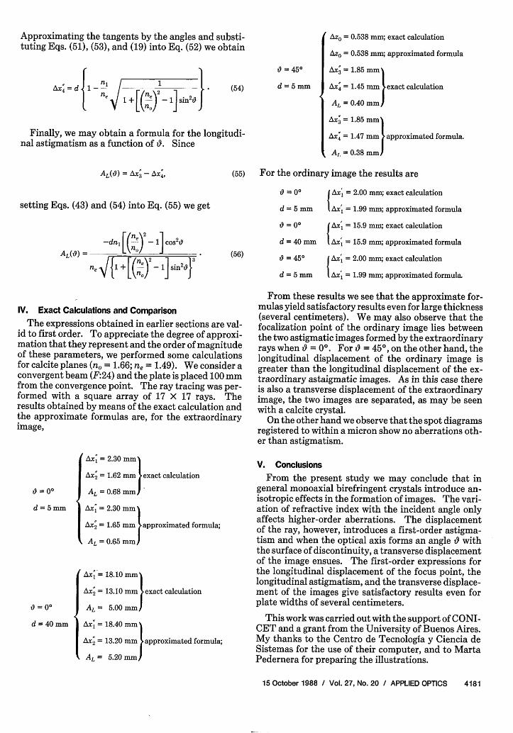
Approximating the tangents by the angles and substi-tuting Eqs. (51), (53), and (19) into Eq. (52) we obtain
= 450
(54)
i a for l f r t
Finally, we may obtain a formula for the longitudi-nal astigmatism as a function of 0. Since
AL(9) = AX - AX4, (55)
setting Eqs. (43) and (54) into Eq. (55) we get
-dn, [( ) 1 2t(
AL('9) = ____Lo cs'9(56)n, 11+ (n)2 - sin2'9}
IV. Exact Calculations and Comparison
The expressions obtained in earlier sections are val-id to first order. To appreciate the degree of approxi-mation that they represent and the order of magnitudeof these parameters, we performed some calculationsfor calcite planes (n = 1.66; ne = 1.49). We consider aconvergent beam (F:24) and the plate is placed 100 mmfrom the convergence point. The ray tracing was per-formed with a square array of 17 X 17 rays. Theresults obtained by means of the exact calculation andthe approximate formulas are, for the extraordinaryimage,
0 = 0o
d = 5mm
= 0
d = 40 mm
Ax; = 2.30 mm
Ax; = 1.62 mm exact calculation
AL =0.68 mm
Ax; = 2.30 mm
Ax; = 1.65 mm approximated formula;
AL = 0.65 mm
Ax '= 18.10 mm
Ax = 13.10 mm exact calculation
AL= 5.00 mm
I Ax = 18.40 mm
AX; = 13.20 aprx ated formula;
IAL= 5.20 mm
d =5 mm
Azo = 0.538 mm; exact calculation
Azo = 0.538 mm; approximated formula
Ax; = 1.85 mm
Ax4 = 1.45 mm exact calculation
AL = 0.40 mm
Ax; = 1.85 mm
Ax; = 1.47 mm approximated formula.
Al = 0.38 mm)
For the ordinary image the results are
'9 Axl = 2.00 mm; exact calculation
d = 5 mm I Ax, = 1.99 mm; approximated formula
9 = 00 Ax = 15.9 mm; exact calculation
d = 40 mm 1 Ax, = 15.9 mm; approximated formula
9 450 fAx = 2.00 mm; exact calculation
d = 5 mm l Ax, = 1.99 mm; approximated formula.
From these results we see that the approximate for-mulas yield satisfactory results even for large thickness(several centimeters). We may also observe that thefocalization point of the ordinary image lies betweenthe two astigmatic images formed by the extraordinaryrays when t0 = 0°. For = 450, on the other hand, thelongitudinal displacement of the ordinary image isgreater than the longitudinal displacement of the ex-traordinary astaigmatic images. As in this case thereis also a transverse displacement of the extraordinaryimage, the two images are separated, as may be seenwith a calcite crystal.
On the other hand we observe that the spot diagramsregistered to within a micron show no aberrations oth-er than astigmatism.
V. Conclusions
From the present study we may conclude that ingeneral monoaxial birefringent crystals introduce an-isotropic effects in the formation of images. The vari-ation of refractive index with the incident angle onlyaffects higher-order aberrations. The displacementof the ray, however, introduces a first-order astigma-tism and when the optical axis forms an angle withthe surface of discontinuity, a transverse displacementof the image ensues. The first-order expressions forthe longitudinal displacement of the focus point, thelongitudinal astigmatism, and the transverse displace-ment of the images give satisfactory results even forplate widths of several centimeters.
This work was carried out with the support of CONI-CET and a grant from the University of Buenos Aires.My thanks to the Centro de Tecnologia y Ciencia deSistemas for the use of their computer, and to MartaPedernera for preparing the illustrations.
15 October 1988 / Vol. 27, No. 20 / APPLIED OPTICS 4181
i .

Appendix: Calculation of AX3From the geometric construction of Fig. 6 we ob-
tained the following expression for the longitudinaldisplacement of the focus:
Ax = -x0 d -( o) (Al)
[see Eq. (40) in the text]. On the other hand, we knowthat Az and Az, are given by relations (40) and (41) ofthe text. Substituting these in Eq. (Al), we obtain
Ax;=X;-Xo#d Ir tanp2 - tanp;L \ tana )
(A2)
account that 02 tanp0 is much less than one, and ig-noring terms in 02 we obtain
tanfl n + b* cos2 9 - tan2 P +t(1 + b* sin 2 9 tanpt.
(A8)
Subtracting (tanp') from both members and consider-ing Eq. (A4) we obtain
tan#; -tanp; = [ 1 + b*[(1 + b* sin 2'9 2J
(A9)
Since j3 may be expressed in terms of a by means ofSnell's law, which to first order is
0; _ nj a,nowhere tanp2 and tanp0 are given by Eqs. (36) and (37):
(A3)tanp = sin#; + b* sin(fl; -9) cosO
cos#2 - b* sin(3 -9) sinO
a -b* sin cos1 + b* sin2 9
where we have defined
b* = (ne) 2
\noJ
(A4)
(A)
Developing the term sin(; - ) in Eq. (A3) andretaining only first-order terms (sin3' = #3 and cosI2 =1), this becomes
,, 13 + b*1; cos2 9 - b* sing cost
1 - b*#; cosO sin + b*sin 2
(A10)
where n' is given by Eq. (19), we obtain
tan; - tanp a n [ 1 + b 1 (All)n0 (1 + 6* sin2 )j
Dividing throughout by tana and substituting its ex-pression given by Eq. (19), this leads to
tanj32-tanp; ni , F 1 + b*tana - n~ l~b* sin' l +lb (A12)tana ne 1(l + b* sin29)2
and substituting Eqs. (A12) and (AS) into Eq. (A2) wefinally obtain
Ax3; d (1 -nine
no 1 + [(re)2 1] sin29)
(A13)
(A)
Dividing the numerator and the denominator by (1+ b* sin2o) and using Eq. (A4), this may be rewritten as
tan2 1 2 ( * S2) + tanp01 l13tn+ b sn 2o 1 + B2 * tanp'
(A7)
Now we know that fO' is small and so is tanp', whichmeans that Eq. (A7) may be developed taking into
References
1. M. C. Simon, "Ray Tracing Formulas for Monoaxial OpticalComponents," Appl. Opt. 22, 354 (1983).
2. M. C. Simon and R. M. Echarri, "Ray Tracing Formulas forMonoaxial Optical Components: Vectorial Formulation," Appl.Opt. 25, 1935 (1986).
3. M. C. Simon, "Wollaston Prism with Large Split Angle," Appl.Opt. 25, 369 (1986).
ICST Gets Name ChangeReflecting its expanded research responsibilities for the develop-ment of computer-related telecommunications standards andguidelines, the NIST Institute for Computer Sciences and Tech-nology has a new name: the National Computer and Telecom-munications Laboratory. The new laboratory retains its formerfunctions and its five divisions: Information Systems Engineering, Sys-tems and Software Technology, Computer Security, Systems andNetwork Architecture, and Advanced Systems.
4182 APPLIED OPTICS / Vol. 27, No. 20 / 15 October 1988